| Title | Size | Downloads |
|---|---|---|
| H3C UIS HCI Appliances Security Management Guide-5W100-book.pdf | 1.62 MB |
- Table of Contents
- Related Documents
-
| Title | Size | Download |
|---|---|---|
| book | 1.62 MB |
H3C UIS HCI Appliance
Security Management Guide
Document version: 5W100
Copyright © 2023 New H3C Technologies Co., Ltd. All rights reserved.
No part of this manual may be reproduced or transmitted in any form or by any means without prior written consent of New H3C Technologies Co., Ltd.
Except for the trademarks of New H3C Technologies Co., Ltd., any trademarks that may be mentioned in this document are the property of their respective owners.
The information in this document is subject to change without notice.
Contents
Configuring two-factor authentication (2FA)
Configuring ACLs to control access between VMs
Configuring VM console access control
Data integrity and confidentiality
Checking the integrity and tracing the source of a VM template
Configuring replication and erasure coding
Encrypting the tunnel when migrating a VM
Configuring protection against attacks on the system
Configuring distributed dual-stack virtual firewalls
Managing operating system security audit logs
Clearing residual information on VMs
Clearing unnecessary and outdated user information
Clearing residual VM memory information
Managing VM data backup and restoration
Managing system data backup and restoration
Centralized resource management
Centralized resource scheduling
Dynamic resource extension (DRX)
Dynamic resource scheduling (DRS)
Traffic isolation based on port profiles
Traffic isolation based on virtual switches
Background
In addition to security threats in traditional data centers, cloud computing faces the following new security threats and challenges:
· Infrastructure security (network level)
¡ Prone to network attacks. Cloud computing must be based on a network that can be accessed at any time to provide easy-to-access cloud computing resources. However, this also means complex routing and domain settings and vulnerability to attacks such as DNS and DDoS. For IaaS, DDoS attacks can come from both external and internal networks.
¡ Security vulnerabilities introduced because of changes in isolation models. Enterprise networks typically use physical isolation to ensure information security for organizations or departments at different security levels. However, cloud computing uses logical isolation to isolate different enterprises, as well as different organizations and departments within the enterprise. This isolation model change can create security vulnerabilities on the enterprise networks.
¡ Risks
of resource sharing. Multitenant resource sharing has brought the following
risks:
User data leakage caused by improper isolation measures.
Attacks from malicious users in the same physical environment.
Insufficient firewall/IPS virtualization capabilities, causing network
partitions and isolation models unable to meet dynamic resource sharing
requirements
· Infrastructure security
¡ VM security threats.
¡ Security threats at the Hypervisor level.
¡ Security threats of open interfaces.
· Data and storage
¡ Security threats to data storage.
¡ Security threats to data processing and transmission.
¡ Data source verification.
¡ Redundant data protection after VM removal.
Security solution
Table 1 UIS all-round security solution
|
Security risk category |
Security solution |
|
Access control |
|
|
Data integrity and confidentiality |
Checking the integrity and tracing the source of a VM template |
|
Intrusion prevention |
|
|
Authentication |
|
|
Residual information |
|
|
Data backup and restoration |
|
|
Centralized resource management |
|
|
|
NOTE: The security features of the HCI kernel are implemented by the kernel. This document will not show the details. |
Access control
Configuring two-factor authentication (2FA)
About this task
With 2FA enabled, users can log in to the system only after they provide a correct USB key and a certificate and username and password, ensuring a more secure login process.
Application scenarios
This feature is applicable to confidential business applications.
Procedure
1. Prepare the root certificate file provided by the USB key vendor.
¡ Make sure the root certificate is correct and the USB key can be used to log in to the system correctly.
¡ The maximum size of the root certificate file is 5MB.
2. On the top navigation bar, click Services,
and then select Security Management > Certificate Configuration
from the left navigation pane.
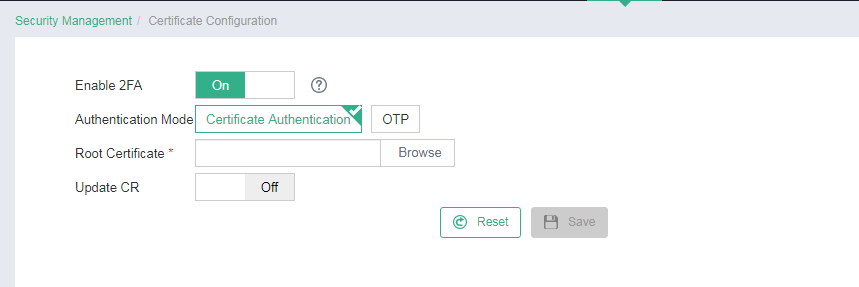
Select Enable 2FA.
Click Browse next to the Root Certificate field to import
the root certificate file. Configure whether to enable CR update as needed.
Figure 1 Configuring 2FA
|
|
NOTE: After you configure 2FA on UIS Manager, complete certificate management tool and browser settings on the host from which you log in to UIS Manager. For more information, see the operating guide provided by the USB key vendor. |
UIS Manager access control
About this task
· UIS Manager access control provides the
following features:
Password policy configuration to control password complexity and validity
period.
· Access control policies based on time ranges and IP addresses to restrict operator access to the UIS management platform.
· Login failure handling mechanism (max failed login attempts and login failure lock), and operator idle timeout.
· HTTPS Only mode to allow access to UIS Manager only through HTTPS.
Application scenarios
This feature is applicable to scenarios where users need to access the UIS management platform by using an enhanced security method.
· To set the password policy, see “Configuring the password policy.”
· To set an access policy to control user access, see “Configuring an access policy.”
· To set login parameters, see “Configuring login parameters.”
· To allow access to UIS Manager only through HTTPS, see “Enabling HTTPS access.”
Procedure
Configuring the password policy
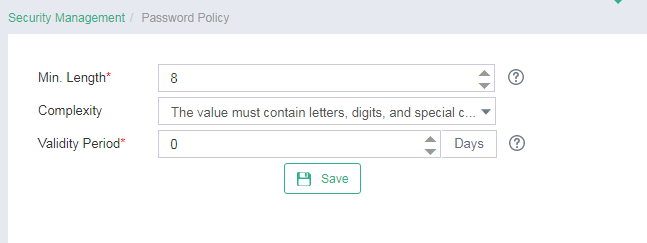
1. On the top navigation bar, click System, and then select Security Management > Password Policy from the navigation pane.
2. Configure the minimum password length, select a password complexity requirement, and then enter the password validity period.
Figure 2 Configuring the password policy
|
|
IMPORTANT: If you log in to the system after the password expires, the system will automatically prompt you to change the password. When you change the password, make sure the new password meets the password policy requirements. |
Configuring an access policy
1. On the top navigation bar, click System, and then select Security Management > Access Policies from the navigation pane.
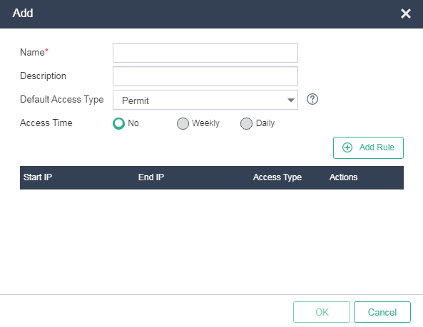
2. Click Add.
3. Configure the access policy name and description, select the action to take on operators that do no match any access policy rules, and configure the time when operators matching the access policy can access the system as needed.
If an operator does match any access rules, the default action will be taken.
Figure 3 Adding an access policy
4. Click Add Rule. Enter the start and end IP addresses and select the access type. Click OK.
Figure 4 Adding an access rule
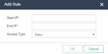
Make sure at least one actions in the rules of an access policy is different from the default action in the access policy.
Configuring login parameters
1. On the top navigation bar, click System, and then select Parameters > System Parameters from the navigation pane.
2. Configure the operator idle timeout, maximum failed login attempts, login failure lockout interval, and maximum number of online operators.
Figure 5 Configuring login parameters
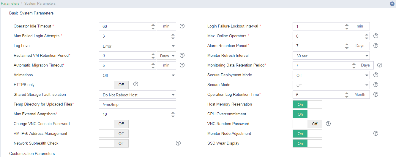
· Operator Idle Timeout: Specify the idle timeout for the operators. An operator automatically logs off of the system when the idle timeout expires. The default value is 10 minutes.
· Login Failure Lockout Interval: Specify the time period during which the IP address that an operator uses to access the system is forbidden from logging in to the system. The default value is 1 minute. The timer starts for an operator's IP address when the number of consecutive login failures of that operator reaches the upper limit.
· Max. Failed Login Attempts: Specify the maximum number of allowable consecutive login failures. If an operator fails to log in to the system for the specified times, the operator's IP address cannot log in to the system within the specified time period.
· Max. Online Operators: Specify the maximum number of online operators. 0 indicates that the number of online operators is not limited.
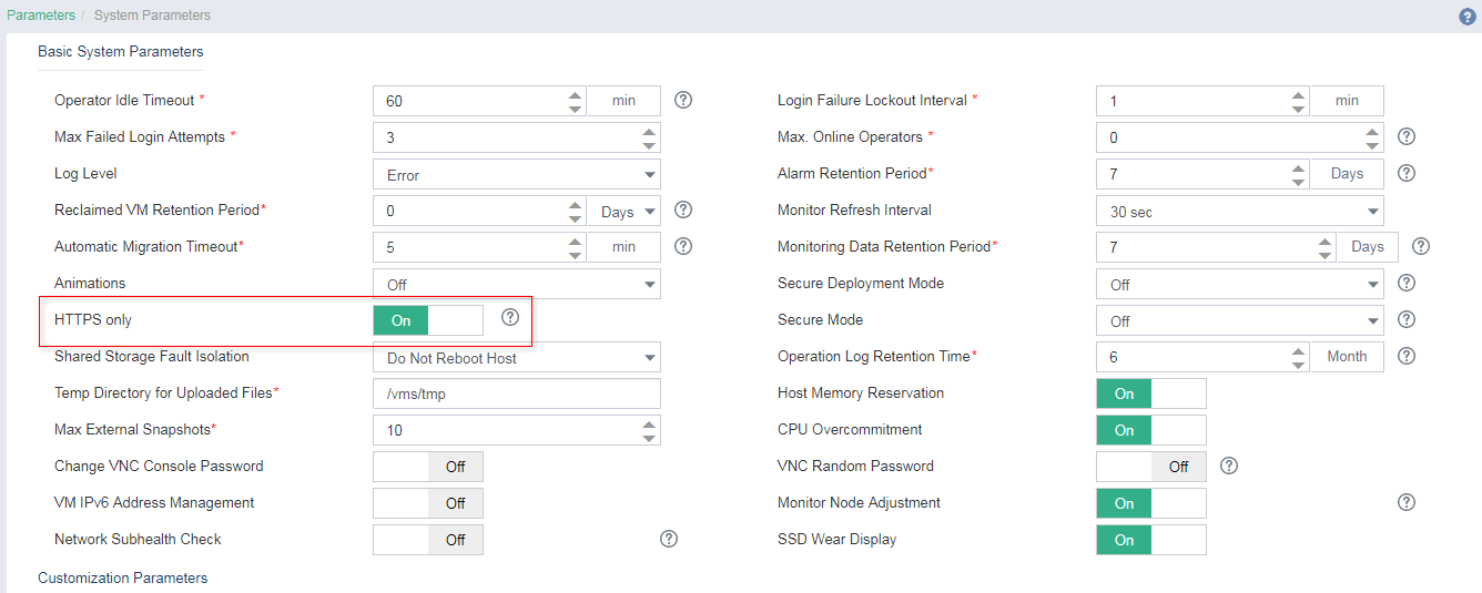
Enabling HTTPS access
1. On the top navigation bar, click System, and then select Parameters > System Parameters from the navigation pane.
2. Select HTTPS Only.
Figure 6 Enabling HTTPS access mode
|
|
IMPORTANT: · Only UIS E0750P02 and later versions support this feature. · After you enable HTTPS only mode, you can access the system only through HTTPS. · Changing HTTPS access mode will restart the UIS-Core service. Make sure no tasks are running and do not perform other operations on the management platform. |
After you enable HTTPS access mode, the system will automatically redirect to the UIS login page at https://X.X.X.X:443, where x.x.x.x is the IP address for logging in to UIS Manager.
Hierarchical user management
About this task
· The operator grouping, authorization, and hierarchical management allows users with different levels and groups to have different management and access permissions.
· To ensure system security, only operators who pass identity authentication (password or LDAP authentication) can log in to UIS Manager. The operations that an operator can perform are determined by the permissions assigned to the operator.
Application scenarios
To address the requirements of data center management, you can assign administrators to different groups with different management and access privileges.
· System admin group—Also known as the super administrator. It can create and manage all cloud resources within the data center.
· Custom admin group—You can assign users to different groups as needed. Users in a group have only the access and management privileges of the group to which they belong after they log in to UIS Manager.
· Security auditor group—Has only the view privilege.
Figure 7 Managing operator groups
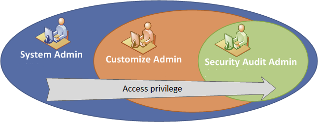
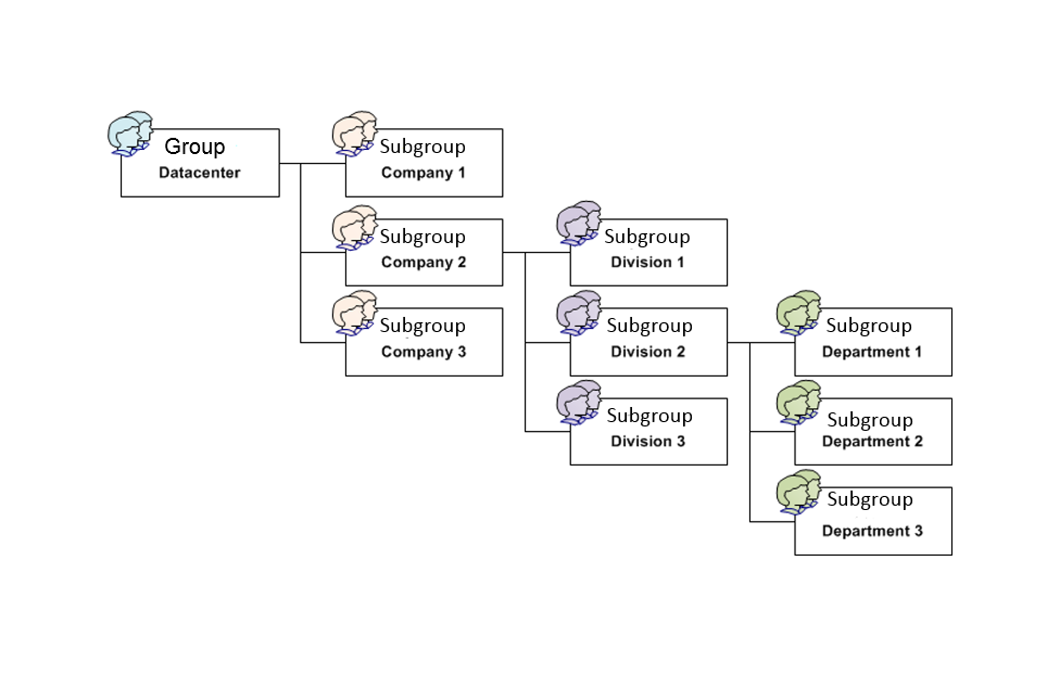
Figure 8 Managing operator groups and subgroups
Procedure
|
|
CAUTION: The UIS system is a not an open system. Except for the administrator user, you cannot add other users to the system backend or database or delete existing users. If you fail to do so, system anomalies might occur. |
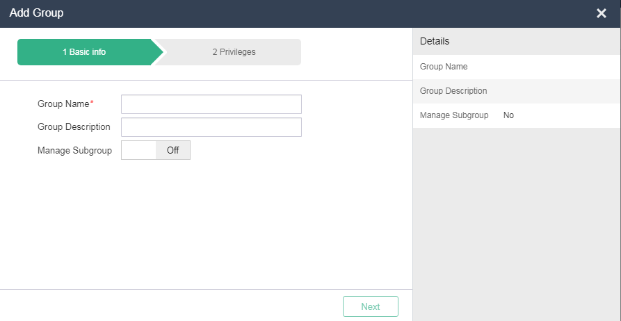
2. Click Add Group.
3. Enter the group name and description, and select whether to enable subgroup management as needed.
Figure 9 Adding an operator group
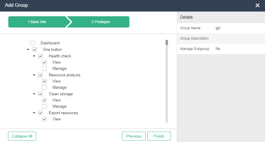
4. Click Next. Select the privileges for the group.
Figure 10 Selecting privileges
5. To add a subgroup for a group, click the ![]() icon
in the Actions column for that group.
icon
in the Actions column for that group.
6. Repeat the previous steps to configure subgroup information.
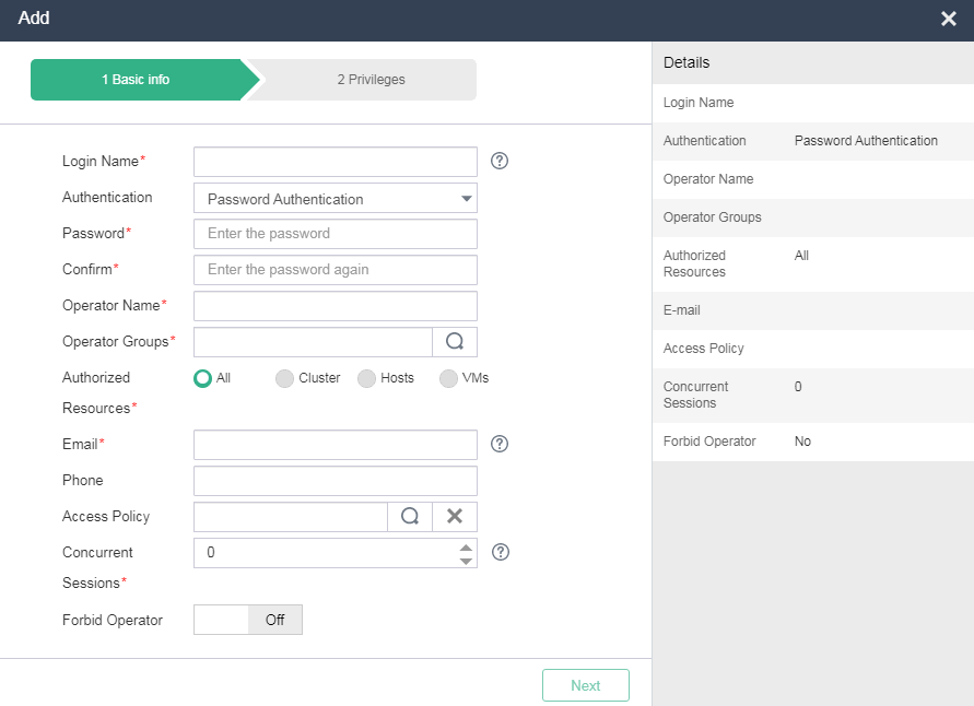
7. On the top navigation bar, click System, and then select Operators & Groups > Operators from the navigation pane.
8. Click Add.
9. Configure the operator parameters as needed.
Figure 11 Adding an operator
|
|
NOTE: If you select All as the authorized resources for an operator, you must select operation privileges for that operator. If you select Cluster, Hosts, or VMs, you must select the clusters, hosts, or VMs that the operator can manage. The operation privileges of the operator are determined by the operator group to which the operator belongs. |
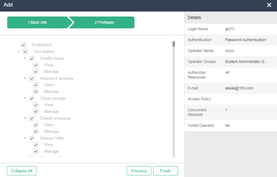
10. Click Next. Select the privileges for the operator.
Figure 12 Selecting privileges
|
|
NOTE: The actual operation privileges of an operator are a combination of the privileges of the operator group to which that operator belongs and the privileges specific to that operator. |
Configuring ACLs to control access between VMs
About this task
ACL, a security control technology based on packet filtering, contains a set of rules for identifying packets and processing traffic according to configured network policies.
ACLs can be used for access control. You can configure traffic limits and network priorities for ACLs to enhance the network performance.
For example, you can use ACLs for access control between VMs to ensure the security of service resources deployed on VMs.
You can configure Layer 2, Layer 3, Layer 4, and time-based ACLs to meet the needs in various service scenarios.
Application scenarios
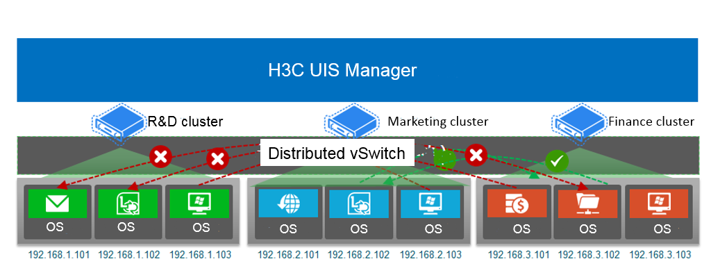
As shown in Figure 13, an enterprise data center has R&D, marketing, and finance clusters. All VMs in the R&D cluster store the core code of the enterprise. To prevent technology leaks, use ACLs to control access between VMs in the clusters as follows:
· Deny access between the VMs in the R&D cluster and those in the marketing cluster.
· Deny access between the VMs in the R&D cluster and those in the finance cluster.
· Permit access between the VMs in the marketing cluster and those in the finance cluster.
Figure 13 ACL application scenarios
|
|
NOTE: In production environments, services might be assigned to clusters, hosts, or VMs in hosts, based on the scale of the data center. |
Procedure
Creating an ACL
1. On the top navigation bar, click System, and then select Security Management > ACLs from the navigation pane.
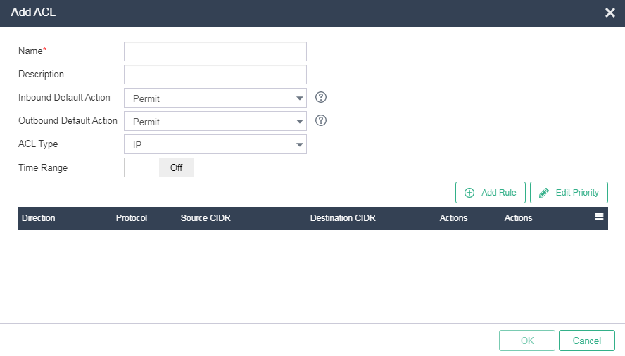
2. Click Add. Configure a name and description, set the inbound/outbound default action to Permit, set the ACL type to IP, and configure the effective time for the ACL as needed.
Figure 14 Adding an ACL for the R&D cluster
ACL parameters
¡ Default Inbound Action—Select the action to take on inbound packets that do not match any rules. Options include Permit and Deny. The default action is Permit.
¡ Default Outbound Action—Select the action to take on outbound packets that do not match any rules. Options include Permit and Deny. The default action is Permit.
¡ ACL Type—Select an ACL type. Options include IP and Layer 2.
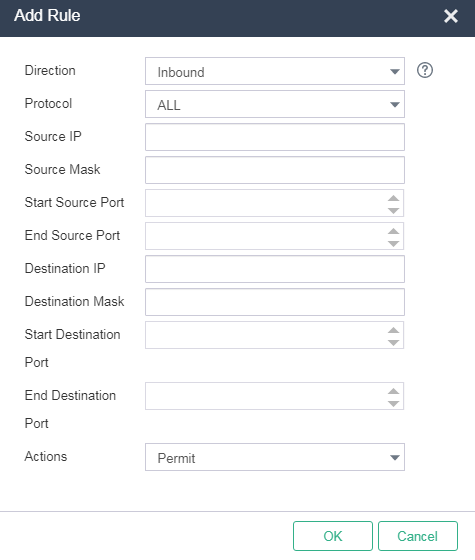
3. Click Add Rule. Configure ACL rules between the R&D cluster and marketing cluster, and between the R&D cluster and finance cluster.
Figure 15 Adding a rule
4. Click OK.
Creating a port profile
1. On the top navigation bar, click Networks, and then select Port Profiles from the navigation pane.
2. Click Add. Enter a name and description.
Figure 16 Creating a port profile
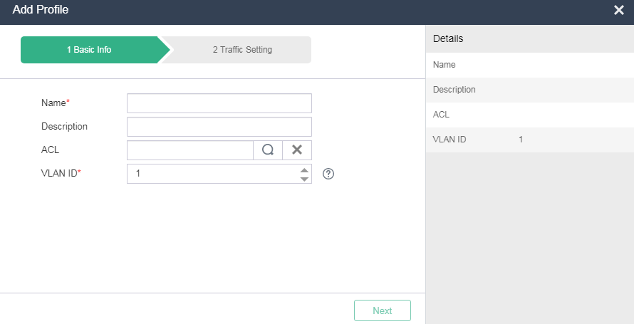
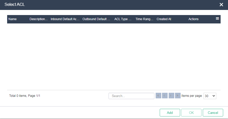
3. Click the ![]() icon in the ACL field,
and select the ACL created in "Creating an ACL." Configure the VLAN ID, traffic limit
settings, and network priority as needed.
icon in the ACL field,
and select the ACL created in "Creating an ACL." Configure the VLAN ID, traffic limit
settings, and network priority as needed.
Figure 17 Selecting an ACL
Applying a port profile to a VM
1. On the top navigation bar, click VMs, and then select VMs from the navigation pane.
2. Select the target VM, and then navigate to the Summary page of the VM.
3. Click Edit. In the window that opens, click the Network option.
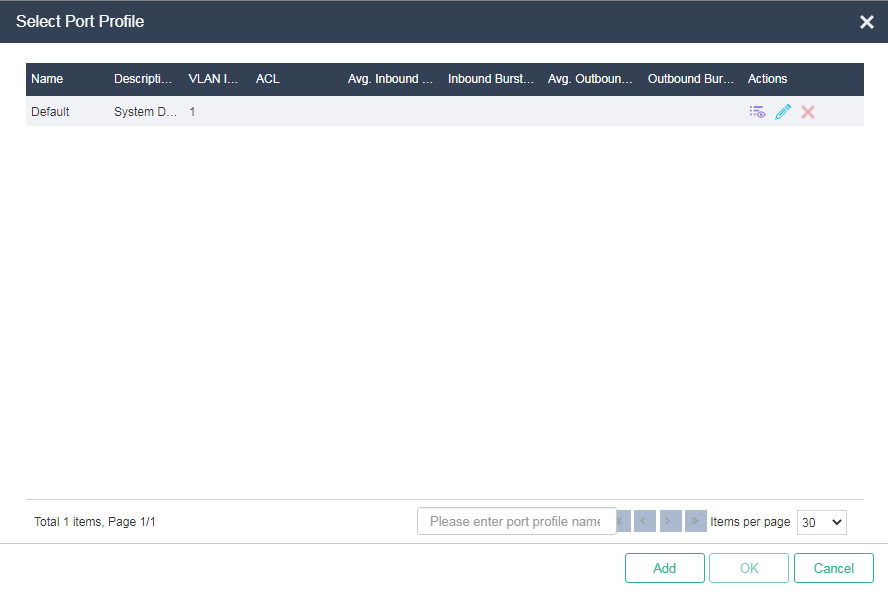
4. Click the ![]() icon in the Port Profiles field. Select the port profile created in "Creating a port profile", and then click
OK.
icon in the Port Profiles field. Select the port profile created in "Creating a port profile", and then click
OK.
5. Click Apply.
Figure 18 Selecting a port profile
Configuring VM console access control
About this task
With Change VNC Console Password enabled, you can set a VNC console password for all newly created VMs on UIS Manager to reduce security vulnerabilities.
You can also configure the system to generate random VNC console passwords for newly created VMs to ensure security.
Application scenarios
You can use this feature to set the password for logging in to the VNC console of VMs. To edit the VNC console password for a specific VM, edit it on the Edit window of the VM.
Procedure
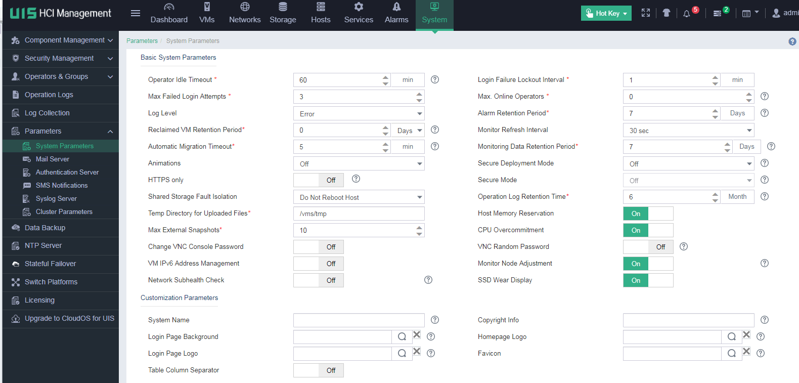
1. On the top navigation bar, click System, and then select Parameters > System Parameters from the navigation pane.
Figure 19 System parameter configuration page
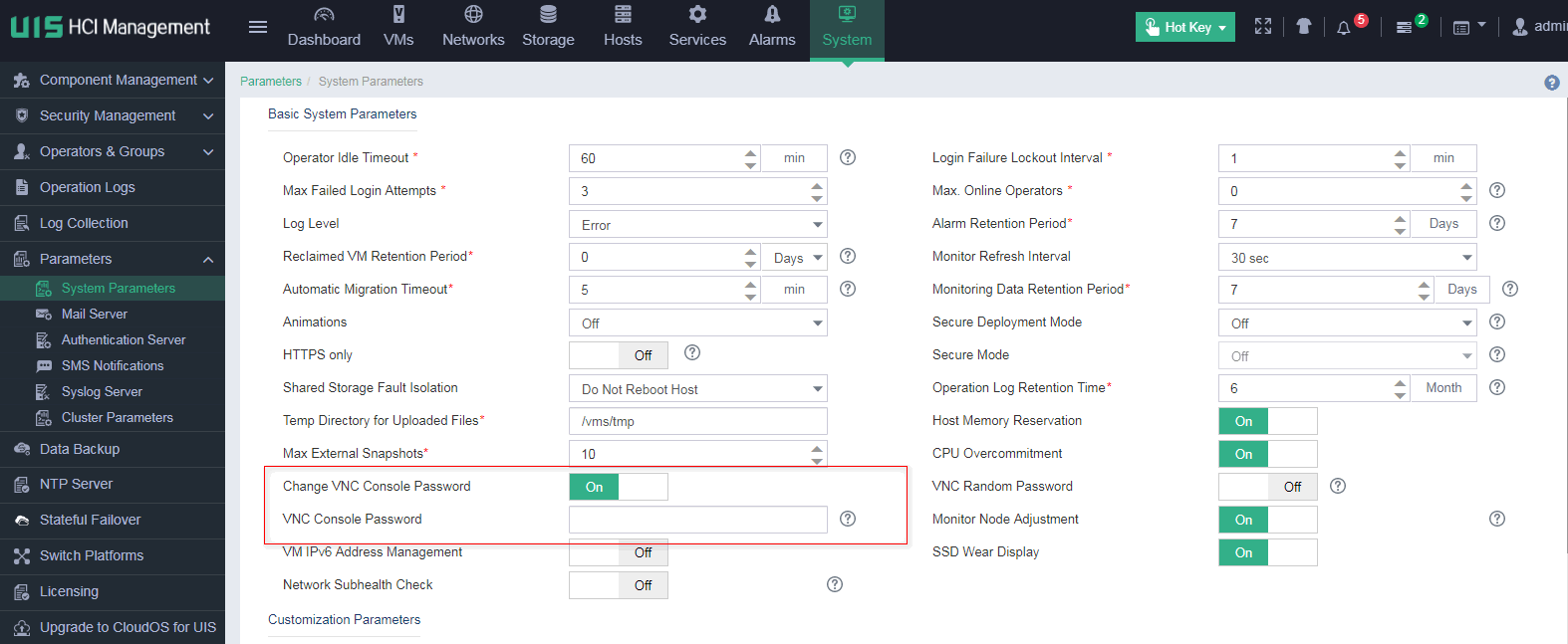
2. Enable Change VNC Console Password, and set the VNC console password.
Figure 20 Setting the VNC console password
3. Click Save.
Data integrity and confidentiality
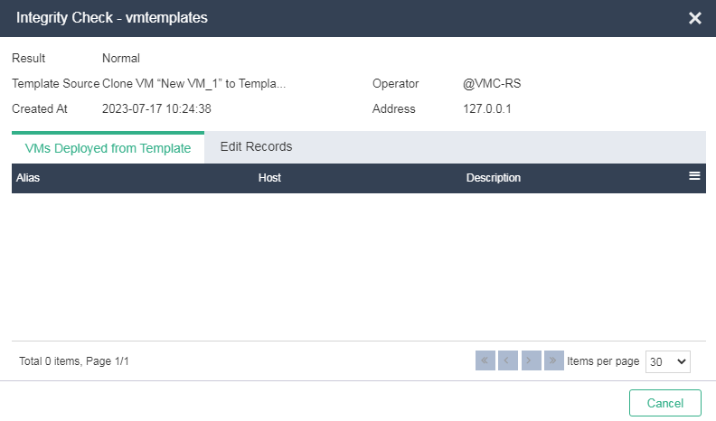
Checking the integrity and tracing the source of a VM template
About this task
You can perform CRC for a VM template file to prevent tampering of the VM template during copy or transmission.
You can trace the sources and authors of VM templates for easy management.
Application scenarios
You can check the integrity and trace the source of a VM template file to prevent tampering of the VM template.
Procedure
1. On the top navigation bar, click VMs, and then select Virtual Templates from the navigation pane.
2. Click the ![]() icon in the Actions column for a template. The system will automatically check the integrity and
trace the source of the template. You can view the
check progress on the page that opens.
icon in the Actions column for a template. The system will automatically check the integrity and
trace the source of the template. You can view the
check progress on the page that opens.
Figure 21 Checking the integrity and tracing the source of a VM template
Configuring replication and erasure coding
About this task
Highly reliable and flexible data redundancy policies (such as 2 or 3 replicas) allow distributing replicas across multiple servers to ensure data availability and durability when server or disk failures occur. The system automatically performs data reconstruction, recovering the replicas lost due to failures.
Application scenarios
The system provides the data redundancy policies:
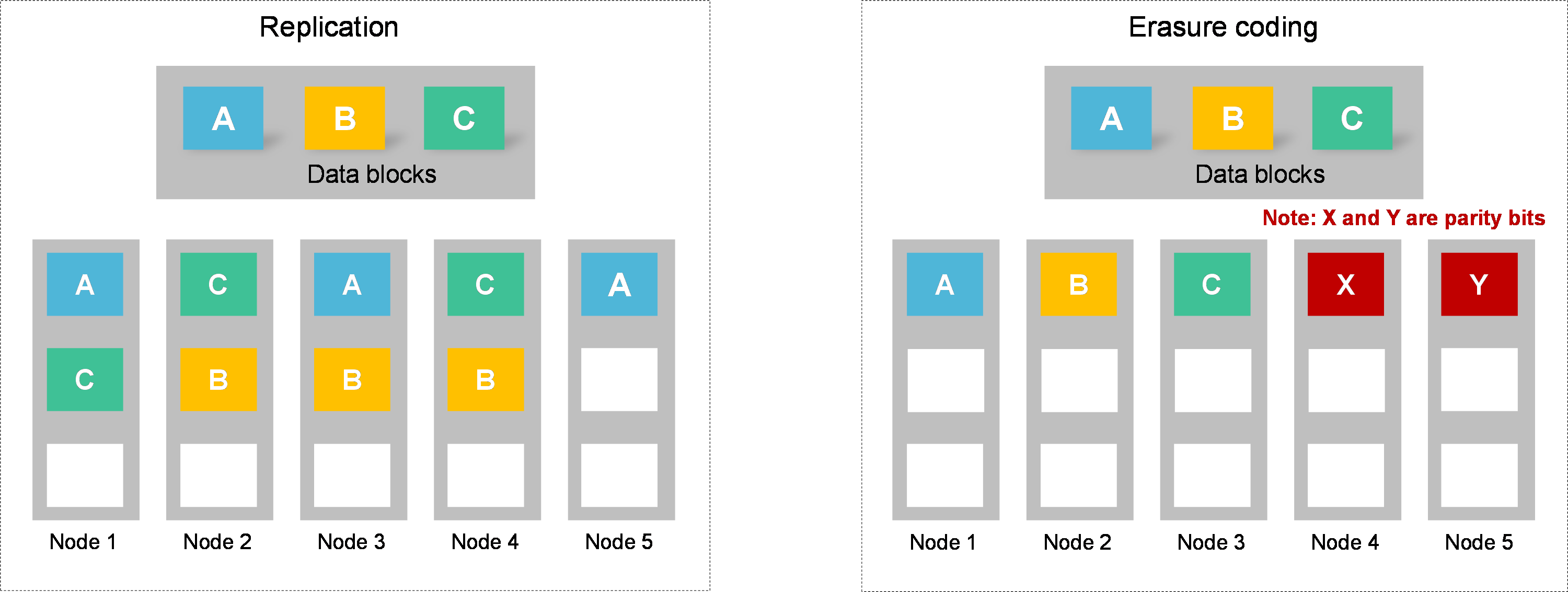
· Replication—Protects data by creating multiple replicas of data. The replicas are preferentially distributed on different disks. Data is available as long as one disk is operating correctly with the replica on the disk being integrated. Data durability increases with the number of data blocks at the expense of storage capacity. If the replication redundancy policy is configured, the storage space usage is 1/N, where N is the number of replicas.
· Erasure Coding—Protects data by breaking data into blocks, which are expanded and encoded with redundant data pieces and stored across a set of different locations or storage media. The system can recover the data from any combination of a smaller number of those blocks. For example, if n data blocks are encoded with redundant data pieces to generate m parity blocks, data is available when a maximum of m blocks (including data blocks and parity blocks) fail. Encoding refers to the process of generating parity blocks, and decoding refers to the process of restoring data blocks. If the erasure coding redundancy policy is configured, the storage space usage is n/(n+m).
Replication is mainly used in production systems with higher performance and reliability requirements. Erasure coding provides higher storage usage efficiency and potentially higher fault tolerance than replication. However, erasure coding is more complex, requires more computation, and potentially increases the time to recover from failure. Erasure coding policies apply to read-only data and cold data such as VM backup files and VM templates.
Figure 22 Replication and erasure coding
Procedure
During initialization or creation of a new data pool, you can specify a replication or erasure coding redundancy policy to ensure data security. For more information, see H3C UIS Manager Help and H3C UIS Manager Distributed Storage Configuration Guide.
Encrypting the tunnel when migrating a VM
About this task
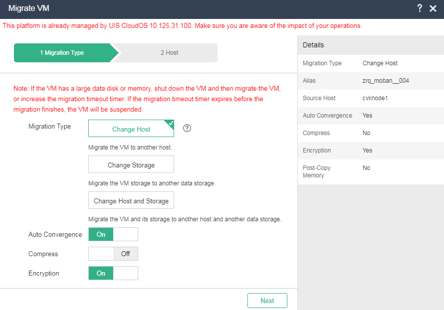
When you migrate a VM by changing the host or both host and data storage, you can enable encryption to ensure the security of transmitted data.
Application scenarios
You can enable encryption for migration of highly important VMs. With encryption enabled, the migration speed will slow down.
Procedure
1. On the top navigation bar, click VMs, and then select VMs from the navigation pane.
2. Select the target VM, and then navigate to the Summary page of the VM.
3. Click Migrate.
Figure 23 Migrating a VM
Enabling secure mode for VMs
You can enable the secure mode on the system to further ensure the security of VM data. With secure mode enabled, the following restrictions apply:
· A storage volume can be used by only one VM.
· The login names of operators cannot be edited.
· An operator account can be used by only one user at a time.
· Users can access UIS Manager only through HTTPS.
Intrusion prevention
Configuring protection against attacks on the system
About this task
The system can prevent the following attacks:
· Cross-site scripting—Cross-site scripting attacks are a type of attack where attackers exploit insecure websites as platforms to launch attacks on users that access the website.
· SQL injection—SQL injection attacks are a type of attack where attackers insert SQL commands into the input fields of Web forms or query strings requested by pages, tricking the server into executing malicious SQL commands.
· Cross-site request forgery—Cross-site request forgery attacks are a type of attack where attackers deceive a logged-in user into loading a page containing a malicious request. They use the browser's automatic credential-sending function through the request to inherit the user's identity and privileges, and perform malicious operations, such as changing the user's password or personal information.
· Sensitive data exposure.
· File upload and download.
Application scenarios
This feature is applicable to scenarios with higher security requirements.
Procedure
You can enable the anti-virus feature for VMs and hosts on the system. For more information, see H3C UIS Manager VM Anti-Virus Configuration Guide.
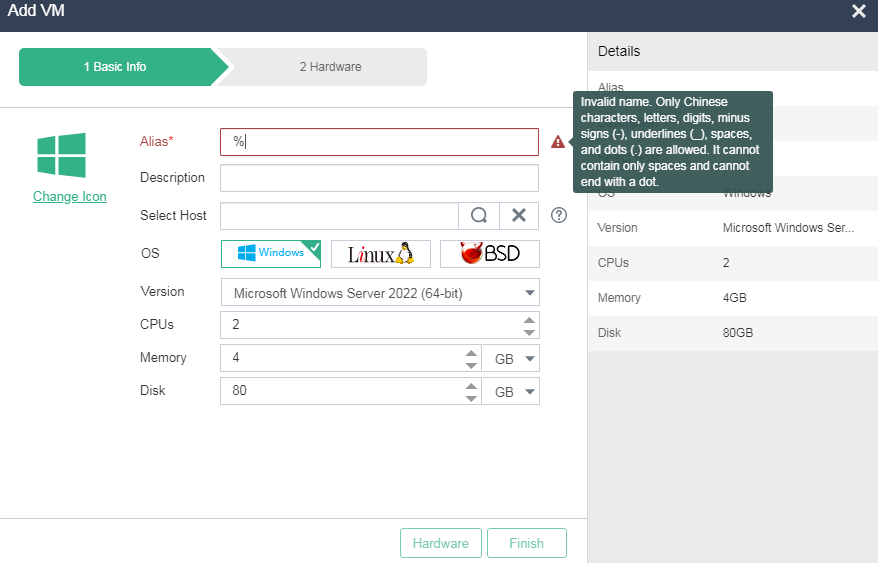
The system provides data validation on webpages to prevent attackers from using special characters to initiate attacks on the system. For example, when you specify an alias for a VM to be added, you can enter only characters that meet the requirements.
Figure 24 Alias validation
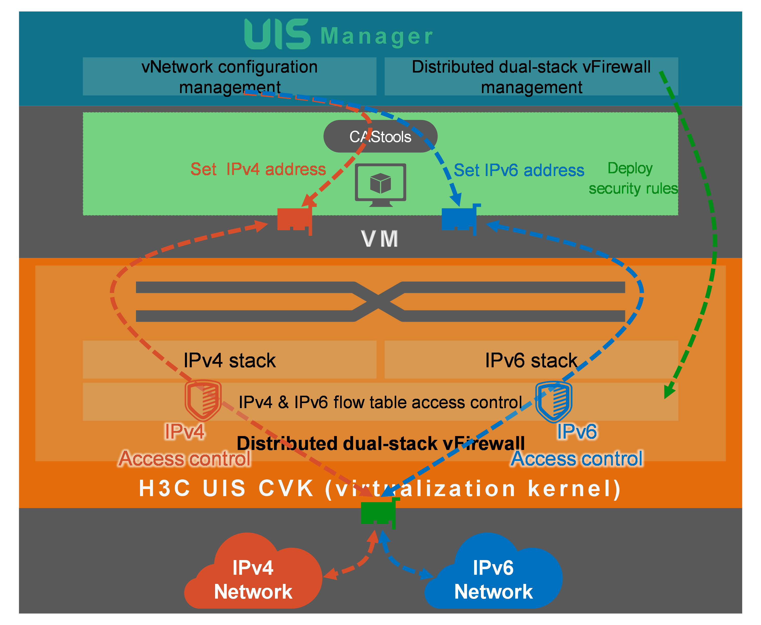
Configuring distributed dual-stack virtual firewalls
About this task
The system supports configuring security rules for state-based or connection-based application protocols such as HTTP, HTTPS, DNS, SSH, RDP, and MySQL.
The system supports configuring bidirectional traffic control, IPv4/IPv6 traffic control, and fine-grained access control based on blacklist and whitelist entries.
The virtual firewall policy takes effect globally. When a VM is migrated, the security rules are migrated together with the VM.
After a VM is migrated, the IPv4 and IPv6 flow tables are migrated together with the VM, providing on-demand network adaptability.
The VMs provide network security isolation measures to divide security zones in the cloud.
Figure 25 Configuring distributed dual-stack virtual firewalls
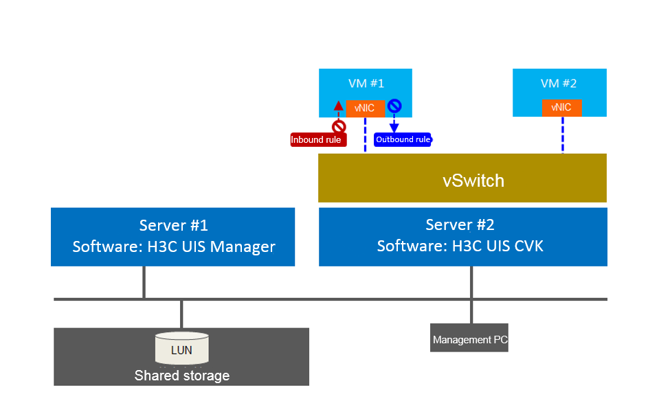
Application scenarios
As shown in Figure 26, an enterprise data center is deployed with services such as Web, mail, production, and finance. The finance service is a key service and independently deployed on a single VM. You can configure a virtual firewall to provide network access control for the finance service VM to ensure the secure operation of the services on the VM. For example, to effectively protect and control the east-west traffic access in the data center and prevent attacks and information theft between VMs on the same host, you can configure the VM to open only TCP port 666 for access.
Figure 26 Virtual firewall application scenarios
Procedure
Adding a virtual firewall
1. On the top navigation bar, click System, and then select Security Management > Virtual Firewalls from the navigation pane. Click Add. Enter the virtual firewall name and description, and select the firewall type as Whitelist.
Figure 27 Adding a virtual firewall
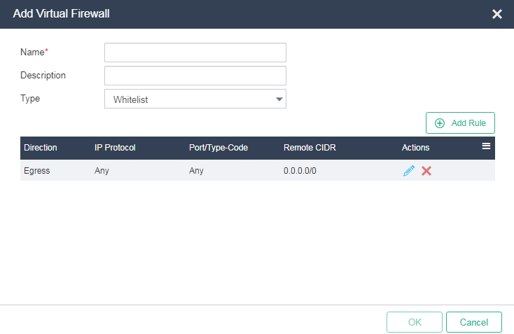
|
|
NOTE: · The system supports the Whitelist and Blacklist virtual firewall types. Packets that match the rules of a whitelist virtual firewall are permitted and other packets are dropped. Packets that match the rules of a blacklist virtual firewall are dropped and other packets are permitted. · When you select the whitelist firewall, no default ingress rule exists, and two default egress rules exist to permit all traffic from the VM to the remote site. (When VM IPv6 Address Management is not enabled, one default egress rule exists to permit all IPv4 traffic). By default, the system denies incoming traffic from the remote site to the VM, but does not deny outgoing traffic initiated from the VM. To permit specific incoming traffic, configure ingress rules as needed. To control traffic from the VM to the remote site, delete the two default egress rules and configure egress rules as needed. · When you configure a blacklist virtual firewall, no default ingress or egress rules exist, and all packets are permitted. To deny specific traffic from the remote site to the VM, configure ingress rules as needed. To deny specific traffic from the VM to the remote site, configure egress rules as needed. |
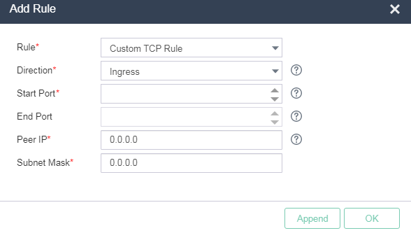
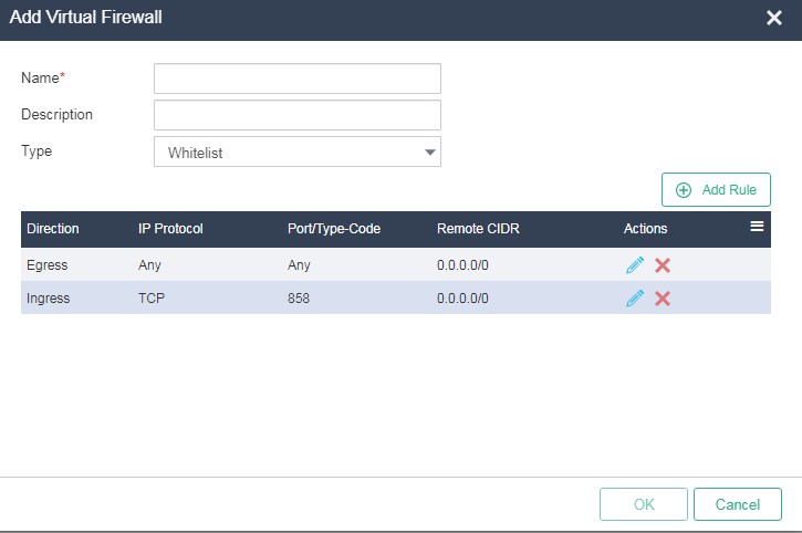
2. Click Add Rule. Select Custom TCP Rule for Rule and Ingress for Direction. Enter the start and end port numbers. Specify both the peer IP address and subnet mask as 0.0.0.0 (which indicates any IPv4 address).
Figure 28 Adding a virtual firewall rule
3. Click OK to return to the page for adding the virtual firewall, verify the rule configuration in the rule list, and then click OK.
Figure 29 Adding virtual firewall rule completed
Applying a virtual firewall to a VM
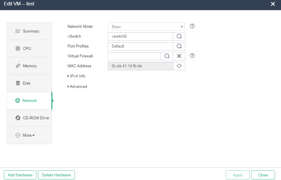
1. On the top navigation bar, click VMs, and then select a VM from the navigation pane. Click Edit on the Summary tab. In the dialog box that opens, click the Network menu.
Figure 30 Editing VM network settings
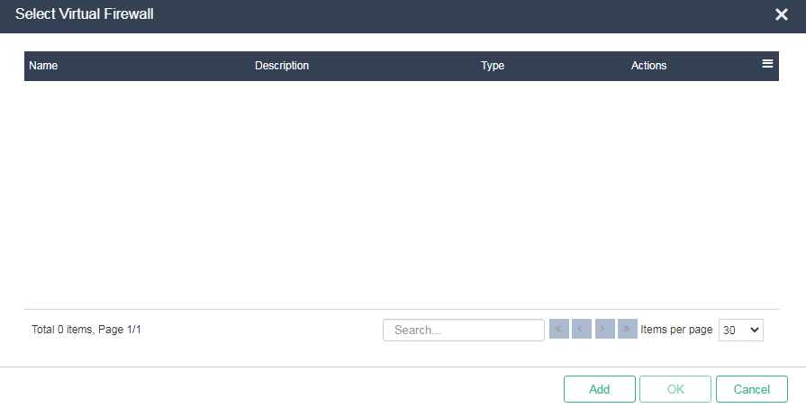
2. Click the ![]() icon for Virtual
Firewall. Select the virtual firewall created in "Adding a virtual firewall" from the virtual firewall list, and click OK to return
to the VM network editing page. Then click Apply.
icon for Virtual
Firewall. Select the virtual firewall created in "Adding a virtual firewall" from the virtual firewall list, and click OK to return
to the VM network editing page. Then click Apply.
Figure 31 Selecting a virtual firewall
VM anti-virus
About this task
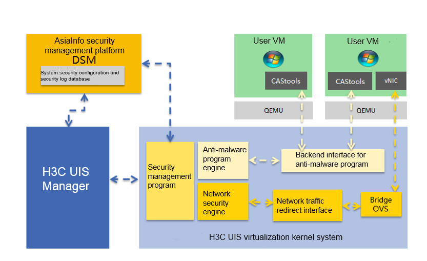
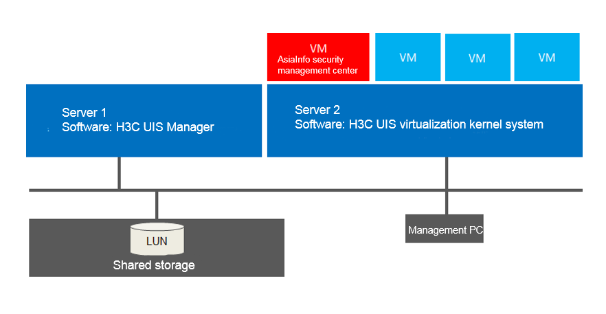
Integrated with the AsiaInfo agentless security solution, H3C UIS HCI platform provides security protection for the VMs on the H3C UIS platform as well as the H3C UIS system. It reduces the scanning time by 75% and resource usage by 70%, as compared to the architecture that uses agents.
The platform supports comprehensive service security protection including anti-virus, IPS/IDS, anti-malware, virtual patching, and firewall.
The platform supports bidirectional stateful firewalls and reduces the attack scope on physical, cloud, and virtual servers through fine-grained filtering and location awareness based on all IP protocols and frames types. It uses the AsiaInfo Security DSM platform to centrally manage server firewall policies, including templates applicable to common server types.
To optimize security operations and avoid anti-virus storms caused by full system scans and signature updates, the platform isolates blocked malicious software, preventing attacks on security platform modules in virtual environments.
Figure 32 Architecture of the AsiaInfo agentless security solution
Application scenarios
Enterprise data centers demand a comprehensive security platform to enhance hyper convergence and cloud project return on investment (ROI), as well as simplifying security operations. The security protection platform can provide security protection for the HCI platform, VMs, application programs, and data. The security protection platform can provide agentless security protection and security modules (including malware prevention, IDS/IPS, virtual patching, and firewall) to build a comprehensive, efficient, autosensing, and hyper-converged security platform that prevents service interruptions and data leakage.
Figure 33 Agentless security application scenarios
Procedure
Installing the hyper-converged host security component
AsiaInfo’s hyper-converged host security component is developed for the H3C UIS HCI platform and is installed as a package on H3C UIS hosts. AsiaInfo delivers the component package to its clients. The core functionality of this software component is offering manageability for the DSM security management center to provide real-time protection of all VMs' network and file system on hyper-converged hosts, and notify DSM security management center of the detection results.
|
|
NOTE: Before installing the security component for hyper-converged hosts, you need to install and configure the AsiaInfo security management center DSM in VMs. For more information, see H3C UIS VM Anti-Virus Configuration Guide. |
To install the hyper-converged host security component:
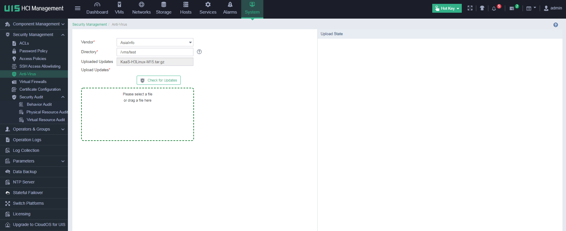
1. Log in to UIS Manager. On the top navigation bar, click System, and then select Security Management > Anti-Virus from the navigation pane. Select AsiaInfo for Vendor, and specify an anti-virus package storage directory.
2. Drag the security component provided by AsiaInfo for hyper-converged hosts from the local directory to the Upload Updates area, and then click Start. After the security component is uploaded, UIS will automatically install the security component silently to all hyper-converged hosts.
Figure 34 Uploading a security component
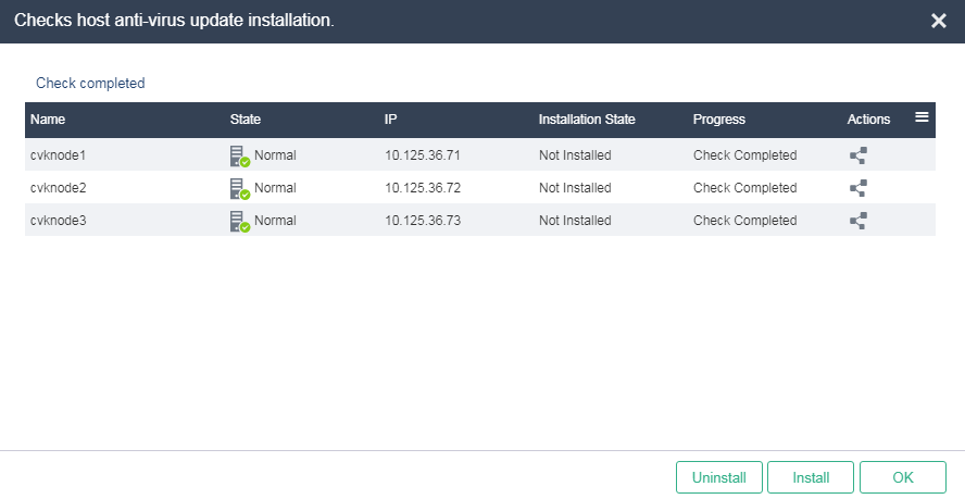
3. Click Check for Updates to verify the security component installation result.
Figure 35 Verifying the security component installation result
Enabling anti-virus for VMs
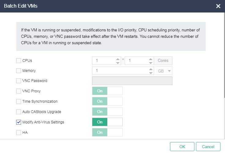
To protect security of a VM, you need to manually enable the anti-virus service for it (disabled by default). The H3C UIS HCI platform supports enabling the anti-virus service for individual VMs and for multiple VMs in bulk.
To enable anti-virus for VMs:
1. In H3C UIS HCI platform, mount CAStools on all VMs that require anti-virus service, and correctly install CAStools on the operating system.
2. On the top navigation bar, click VMs, and then select a VM from the left navigation pane. If multiple clusters exist in the system, you must also select a cluster from the left navigation pane. Click Batch Actions and then select Edit. On the Batch Edit VMs dialog box that opens, select the anti-virus option to enable the anti-virus feature.
Figure 36 Batch enabling anti-virus for VMs
Managing audit logs
About this feature
Audit logs include behavior audit logs, physical resource audit logs, and virtual resource audit logs. The logs record the operations that all operators perform on the UIS Manager.
Application scenarios
The system records and audits all operation logs in the platform to quickly identify malicious operations and attacks.
Procedure
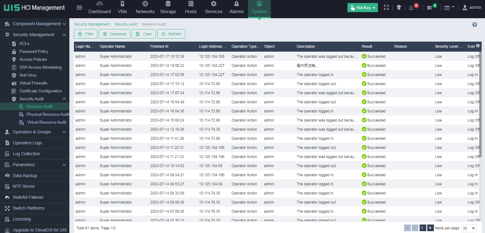
Managing behavior audit logs
1. On the top navigation bar, click System, and then select Security Management > Security Audit > Behavior Audit from the navigation pane. Behavior audit logs record the operator, system configuration, and alarm management operations that all operators perform on UIS.
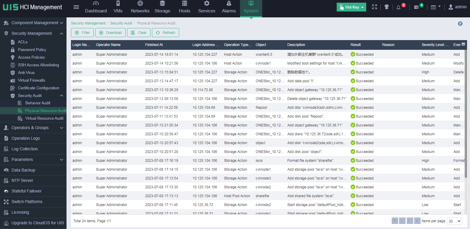
Managing physical resource audit logs
1. On the top navigation bar, click System, and then select Security Management > Security Audit > Physical Resource Audit from the navigation pane. Physical resource audit logs record the host pool, host, and data center operations that all operators perform on UIS.
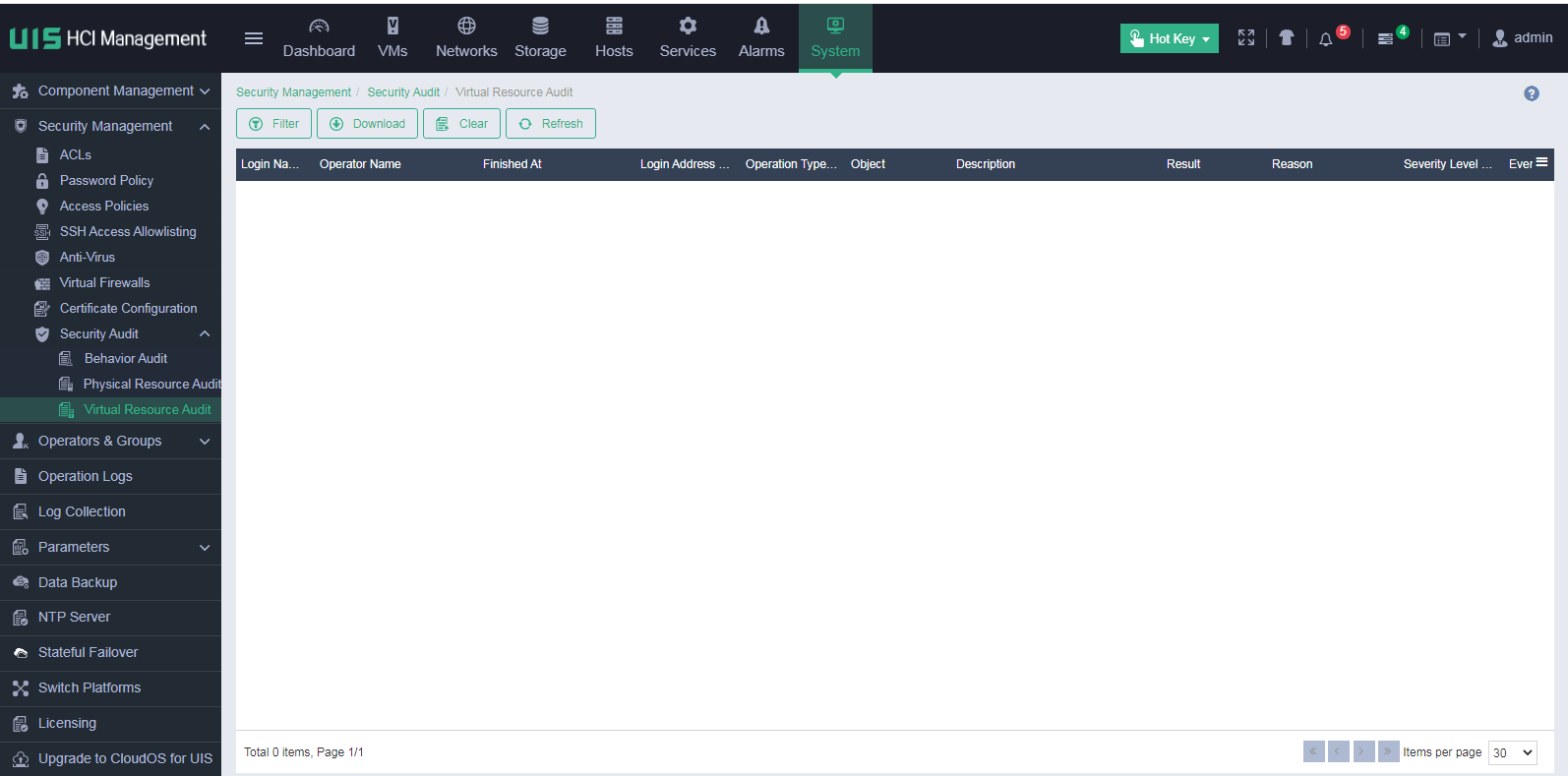
Auditing virtual resources
1. On the top navigation bar, click System, and then select Security Management > Security Audit > Virtual Resource Audit from the navigation pane. Virtual resource audit logs record the VM, template, and cloud rainbow operations that all operators perform on UIS.
Managing operating system security audit logs
About this feature
The operations and behaviors of users logging in to the system are recorded in the /var/log/operation directory.
Application scenarios
This feature applies to the scenarios where security audit is required for the underlying operating system.
Procedure
1. Log in to UIS Manager backend (or the CVM primary server backend in a stateful failover environment).
2. Access the /var/log/operation directory. You can see log files generated based on date, and open the files to view operation records of login users.
Identity authentication
User identity authentication
About this feature
Operators assigned to different groups have different permissions. Users assigned to different groups with different levels have different management and access permissions.
The system provides the password protection function. Upon entering the wrong password for three consecutive times, the account is locked for five minutes. When a login user remains idle for longer than the specified idle timeout timer, the user will be automatically logged out and placed back to the login page.
Application scenarios
This feature applies to the scenarios where different users log in to the platform.
Procedure
None.
Residual information
Clearing residual information on VMs
About this task
Make sure that the data in the VM image file can be cleared from the physical storage device when you delete the VM.
Application scenarios
After releasing storage resources used by a VM, clear all VM data from the physical storage device.
Procedure
1. On the top navigation bar, click VMs, and then select a VM from the left navigation pane. If multiple clusters exist in the system, you must also select a cluster from the left navigation pane.
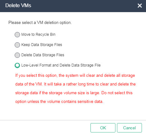
2. Click Destroy VMs on the Summary tab.
3. In the dialog box that opens, select Low-Level Format and Delete Data Storage File, and click OK.
4. In the dialog box that opens, click OK. In the dialog box that opens, enter DELETE as prompted, and then click OK.
Figure 37 Deleting a VM
Clearing unnecessary and outdated user information
About this task
Perform this task to ensure unnecessary operators or operator groups no longer exist on management platform, ensuring security from the user management perspective.
Application scenarios
You can clear operators or operator groups when they are expired, redundant, or incorrectly created.
Procedure
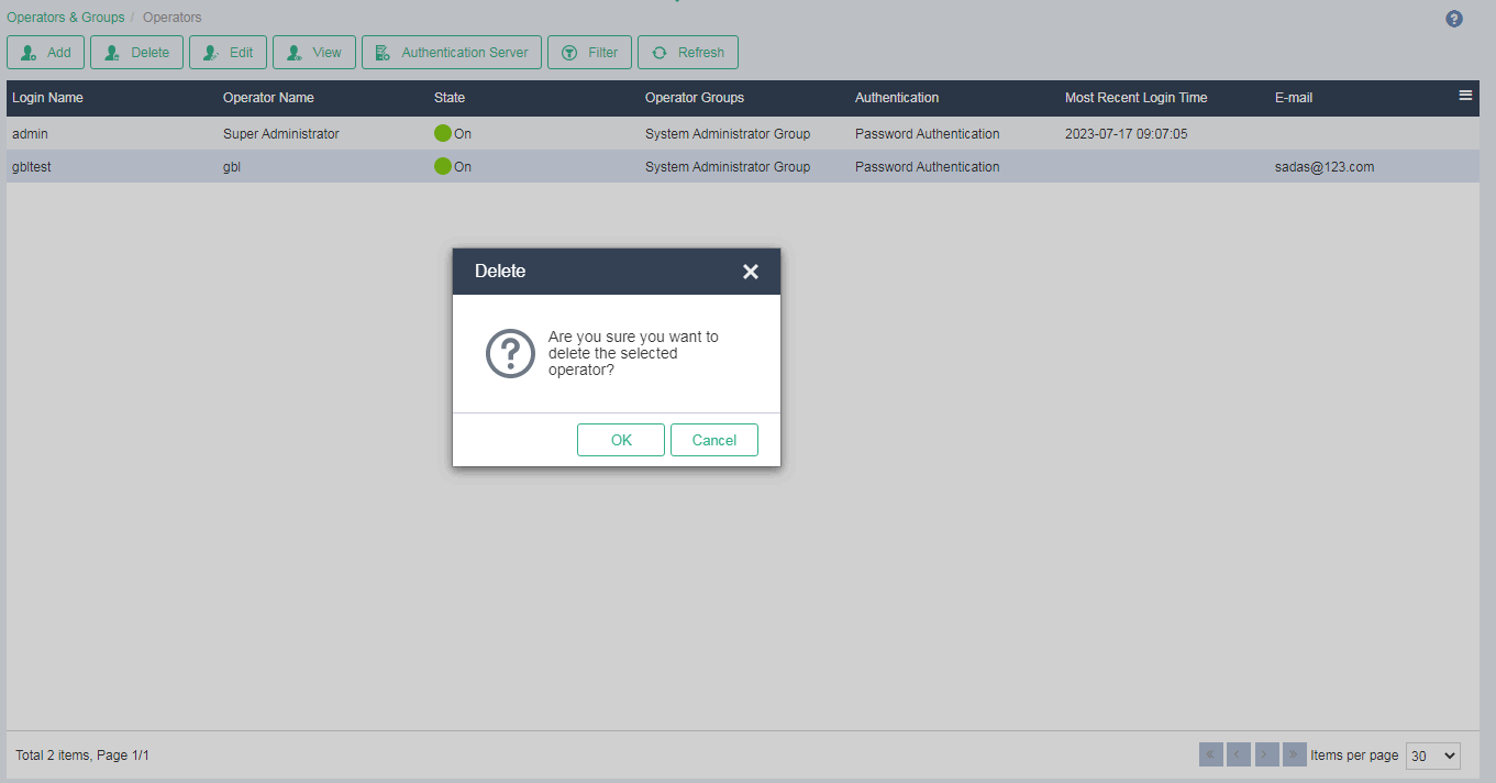
1. On the top navigation bar, click System, and then select Operators & Groups > Operators from the navigation pane.
2. Select the operators to delete, and then click Delete. In the dialog box that opens, click OK.
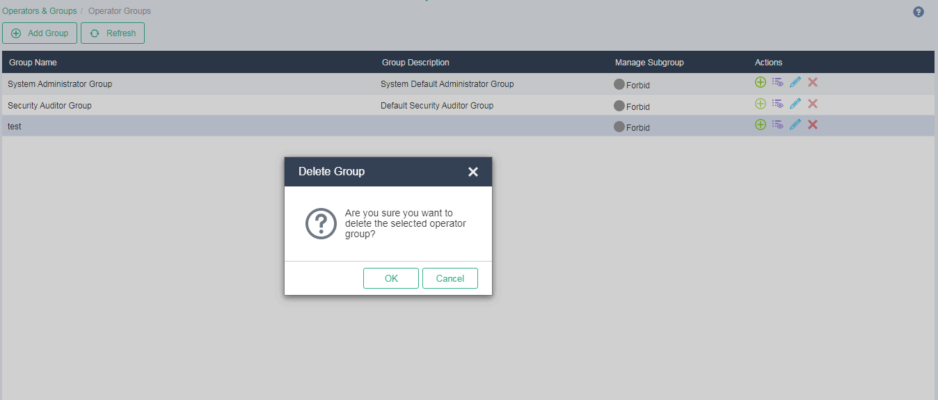
Deleting unnecessary operator groups from the management platform
1. On the top navigation bar, click System, and then select Operators & Groups > Operator Groups from the navigation pane.
2. Click the ![]() icon in the Actions
column for the target operator group (make sure it does not contain any
operators). In the dialog box that opens, click OK.
icon in the Actions
column for the target operator group (make sure it does not contain any
operators). In the dialog box that opens, click OK.
Clearing residual VM memory information
About this feature
After you delete a VM, residual memory data might cause sensitive information leakage. If security hardening is not performed, a server virtualization management platform cannot guarantee complete deletion of sensitive information after memory and storage resources are reallocated.
The UIS HCI kernel automatically clears the physical memory bits mapped to VM virtual memory to ensure that no data remains in the physical memory. Even when memory resources are reallocated to other VMs, it is impossible to recover sensitive memory data of deleted VMs by using professional memory data recovery tools.
Application scenarios
This feature ensures that all memory data of a VM is completely cleared from physical devices when the VM is deleted from the UIS platform.
Procedure
Delete a VM from the UIS Web interface or by using the API.
Data backup and restoration
Configuring stateful failover
About this feature
The stateful failover feature provides disaster recovery for management nodes. If the primary management node fails, the stateful failover feature switches services to the backup management node to ensure minimal or no interruption to business. Stateful failover is achieved through data synchronization replication. The primary management node synchronizes database files and other data to the backup management node in real time via the management network. A local synchronization partition is created on the primary management node to synchronize data other than the database files to the backup management node.
Application scenarios
|
|
IMPORTANT: If UIS is deployed in HCI mode, you must set up a stateful failover system. |
Stateful failover is a disaster recovery solution for the management platform. It ensures business operations continuity when the primary management node fails.
Stateful failover supports the following deployment modes:
· Converged deployment—The primary and backup management nodes are in a service cluster, such as a compute, network, or storage cluster, as shown in Figure 38.
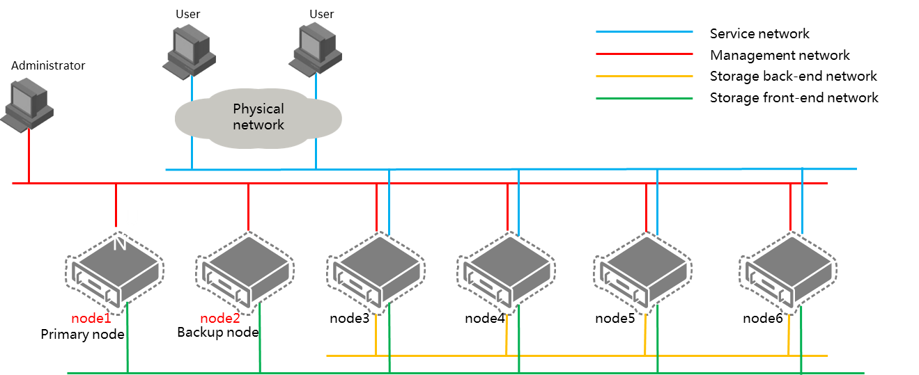
· Distributed deployment—The primary and backup management nodes are independent nodes not in a service cluster, as shown in Figure 39.
Figure 38 Converged deployment
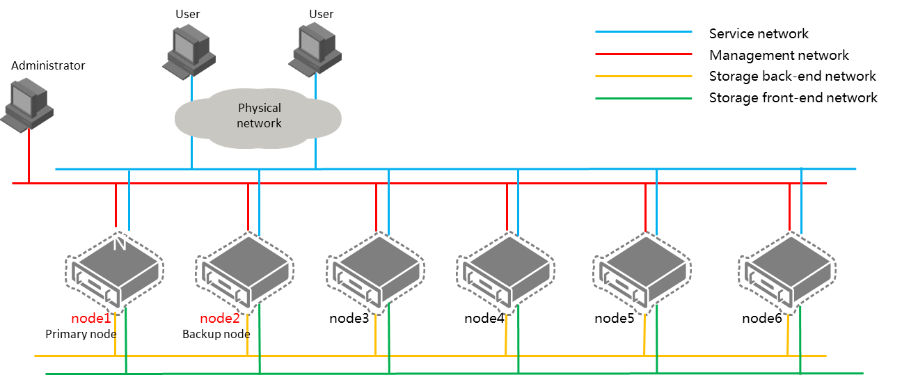
Figure 39 Distributed deployment
Procedure
1. After system initialization is finished, click OK to proceed to stateful failover configuration.
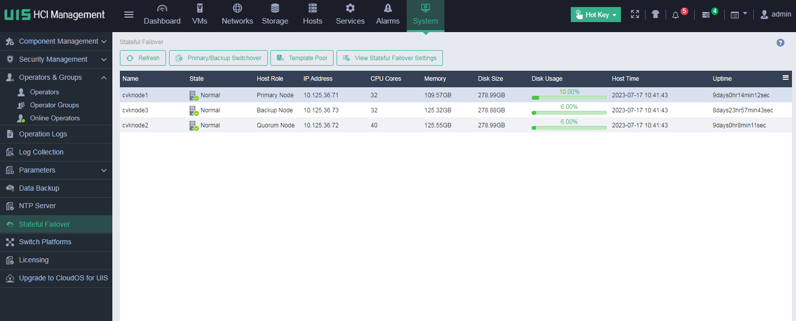
Figure 40 Stateful failover configuration page
2. Click Set Up Stateful Failover System.
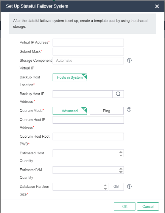
Figure 41 Stateful failover system setup
|
|
NOTE: When you specify the location of the backup host, follow these guidelines: · If you use converged deployment, only Hosts in System is available. · If you use distributed deployment, select an option from Hosts in System and Others. |
3. Enter a virtual IP address, subnet mask, and storage component virtual IP address.
¡ The virtual IP address is the IP address for accessing UIS. The IP address must be an unused address on the management network.
¡ The storage component VIP is the HA management IP address of the distributed storage system. By default the IP address is assigned by the management platform. You can manually specify an available IP address on the management network as the storage component VIP.
4. When you specify the location of the backup host, follow these guidelines:
¡ If you use converged deployment, select Hosts in System.
¡ If you use distributed deployment, select Others, and then select the IP address of the backup management node.
|
|
IMPORTANT: For converged deployment, you must add an independent node to a service cluster through host discovery before you can specify it as the backup management node. |
5. Select a quorum mode, and configure the quorum host IP address, quorum host root password, or two quorum IP addresses.
¡ If you use advanced quorum mode, make sure the quorum host has been installed with the same version of UIS as the primary and backup management nodes. As a best practice, use a host in a service cluster as a quorum host.
¡ If you use ping quorum mode, enter two unique quorum IP addresses that can visit the gateway or are always reachable in the LAN. For two-node deployment mode, use ping quorum mode.
6. Enter the estimated number of hosts and estimated number of VMs. For the database partition size, the management platform can calculate a value for this parameter based on the estimated host quantity and estimated VM quantity. Then, click OK.
Figure 42 Confirming stateful failover system setup
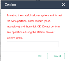
7. In the dialog box than opens, enter confirm and then click OK.
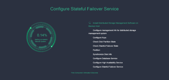
8. UIS starts setting up the stateful failover system. If errors occur, modify incorrect parameters and re-set up the stateful failover system. Detailed information about the errors is saved in /var/log/cvm_master_slave.log.
The management platform then displays the stateful failover system setup progress. Do not close the browser.
Figure 43 Setting up the stateful failover system
9. After the stateful failover system is set up, log in to UIS at the virtual IP address as needed.
|
|
IMPORTANT: · If UIS fails to set up the stateful failover system, check /var/log/cvm_master.log and /var/log/cvm_master_slave.log for detailed cause and phase information. You can modify incorrect parameters and re-set up the stateful failover system. · For distributed deployment, if UIS cannot find the backup management host when re-setting up the stateful failover system after a failure, log in to the backup management host to delete the isCvmFlag file in the /root/.ssh/ directory. |
Managing VM data backup and restoration
About this feature
VM backup and restoration allows you to back up VM data locally or to remote storage. By using the VM restoration or import feature, you can restore the VM backup data to the platform.
Application scenarios
Use this feature if VM data is required to be backed up.
Procedure
Backing up a VM
1. On the top navigation bar, click VMs. From the left navigation pane, select a VM.
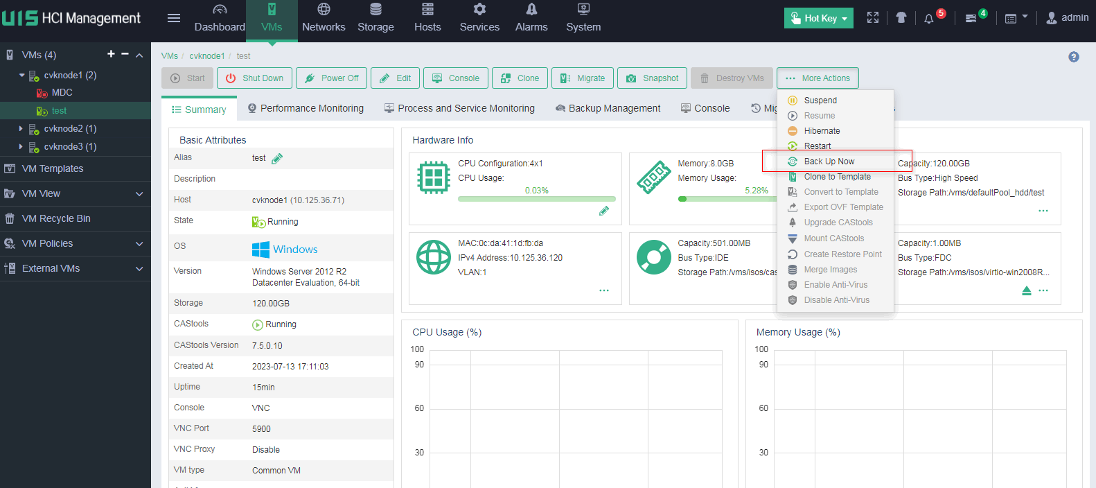
2. On the VM details page, click More Actions, and then select Backup Now.
Figure 44 Selecting a VM
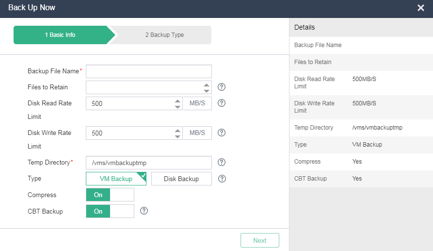
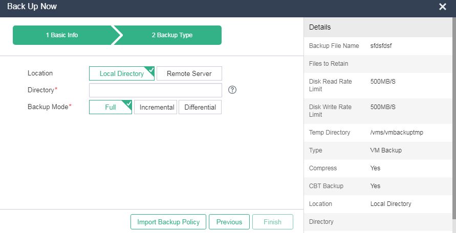
3. Configure the backup parameters, or click Import Backup Policy to select a backup policy. Then, click Finish.
Figure 45 Configuring backup parameters
Restoring a VM
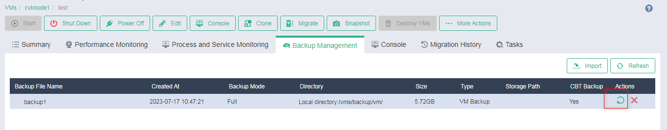
1. On the top navigation bar, click VMs. From the left navigation pane, select a VM.
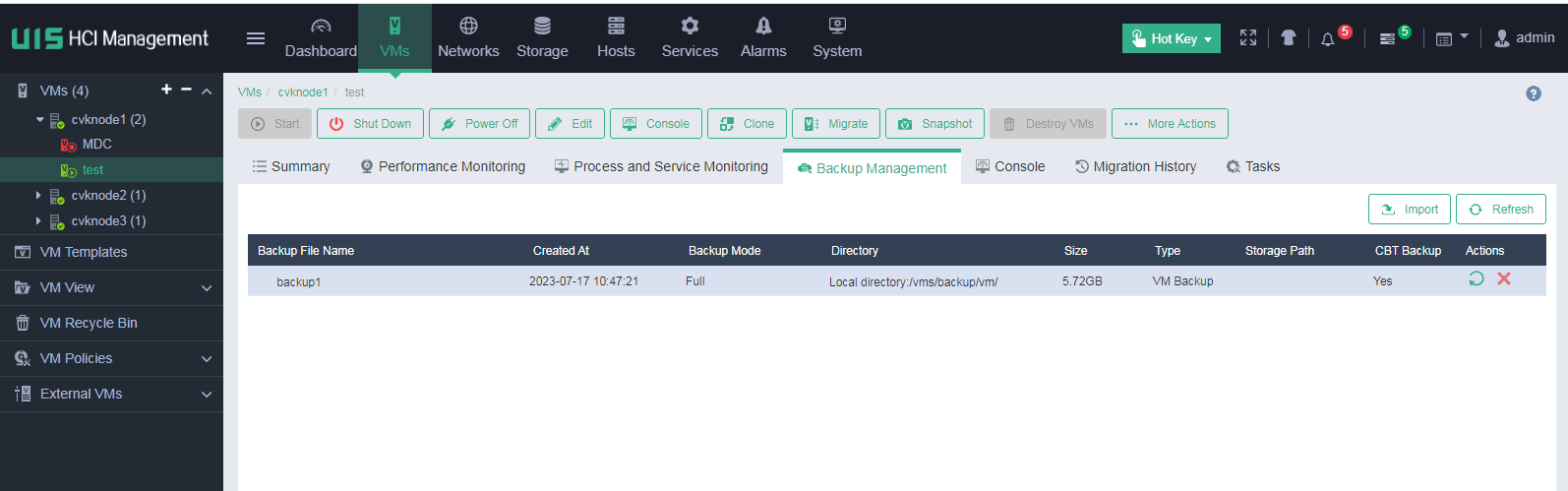
2. On the VM details page, click the Backup Management tab.
Figure 46 VM backup management
3. Click the ![]() icon
in the Actions column for a backup file.
icon
in the Actions column for a backup file.
Figure 47 Selecting a backup file
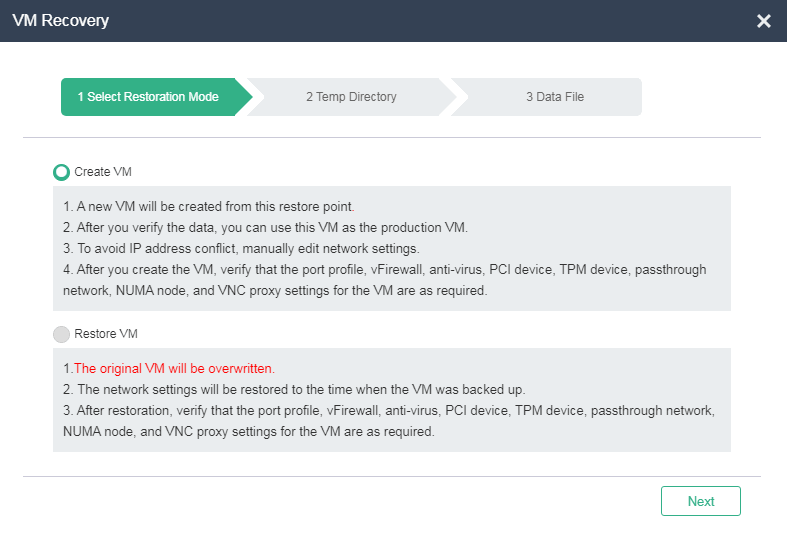
4. Configure the parameters, and then click Finish.
Figure 48 Configuring VM restoration parameters.
5. To restore a deleted VM:
a. On the top navigation bar, click VMs.
b. From the left navigation pane, select a host to restore the VM.
c. Click Import VM.
d. Configure the parameters as needed.
Figure 49 Restoring a deleted VM

Managing system data backup and restoration
About this feature
System data backup and restoration allows you to back up UIS system data locally or to remote storage. If management platform failure causes data loss or the management platform cannot be recovered, you can use the system backup data to restore the management platform.
Application scenarios
Use this feature if system data backup is required.
Procedure
1. On the top navigation bar, click System, and then select Data Backup from the navigation pane.
2. Configure the data backup parameters, and then click Save.
Figure 50 Configuring data backup parameters
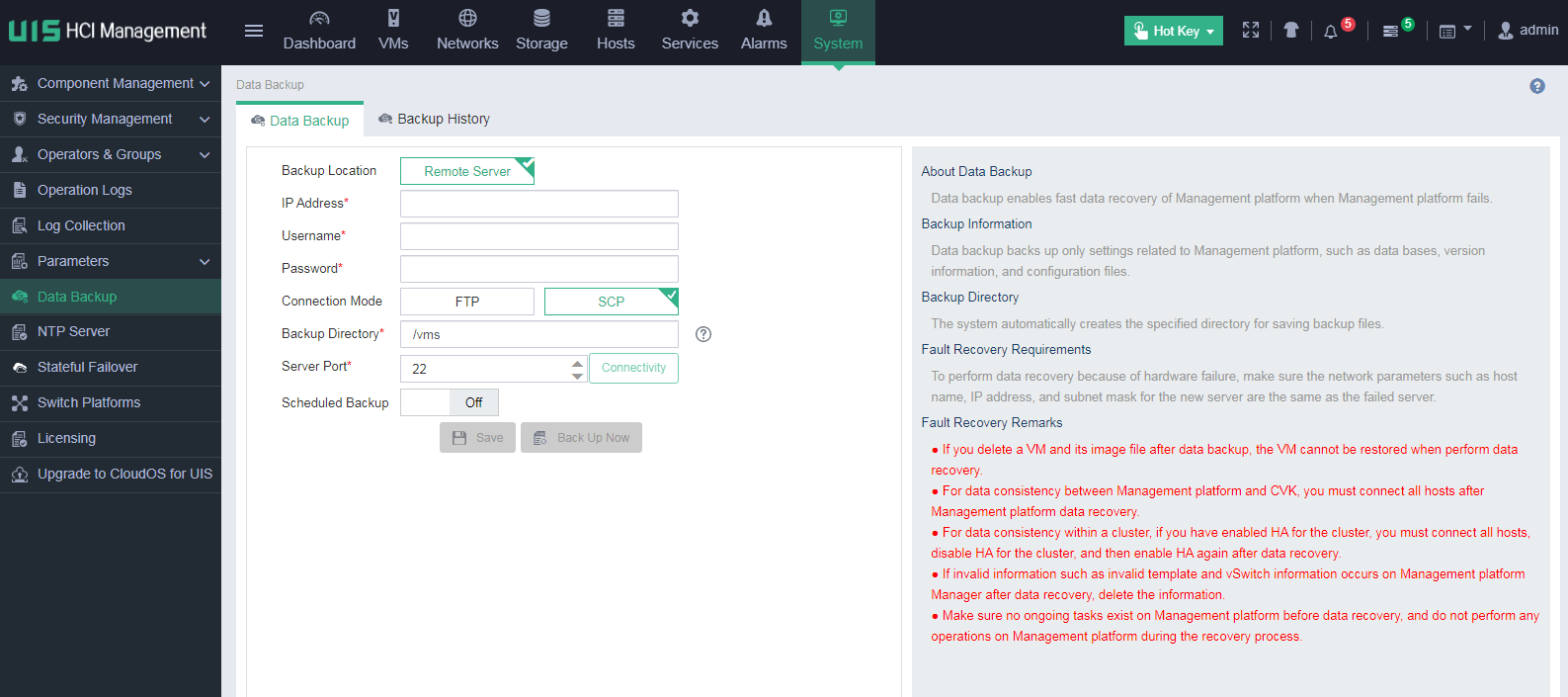
3. To back up the system data, click Back Up Now.
Centralized resource management
Centralized resource scheduling
Dynamic resource extension (DRX)
DRX adds VMs that provide the same service in the same cluster to a VM group. By periodically checking the number of connections, average CPU usage, and average memory usage of VMs in the group, DRX dynamically adjusts the number of VMs in the group based on DRX policies and resource rejection mode, and resource reclaim policies and reclaim mode. With DRX, resource load balancing can be implemented for single-service systems.
Dynamic resource scheduling (DRS)
UIS provides compute DRS and storage DRS.
· Compute DRS—Performs regular monitoring on the CPU usage and memory usage of hosts in a cluster by using the heartbeat mechanism. If the resource usage of a host exceeds the set threshold, the system automatically migrates VMs on the host to other hosts in the cluster until the resource usage of the host falls below the threshold.
· Storage DRS—Monitors the disk I/O throughput, IOPS, or disk usage of shared storage pools on a host and migrates VM image files between the shared storage pools to balance the storage loads.
DRS provides the following benefits:
· Consolidates servers to reduce the IT cost and enhances the service flexibility.
· Reduces the downtime and ensures the service continuity and stability.
· Requires fewer servers and improves the resource usage.
HA
Cluster HA depends on shared storage and dynamic migration technologies to provide simple and efficient HA services for applications running on all VMs in a cluster. It reduces service interruption caused by host hardware failure. Cluster HA is applicable to scenarios that require service continuity. With cluster HA enabled, UIS monitors the operation status of all hosts and VMs in a cluster.
· When a host fails, the management platform migrates the VMs on the host to available hosts in the cluster.
· When a VM fails, the management platform restarts the VM. If the VM is restarted, the management platform does not migrate the VM. If the restart fails, the management platform migrates the VM to another host and restarts it.
· When the network between a host and the shared storage fails, the management platform migrates the VMs on the host to available hosts in the cluster.
Central monitoring
Monitoring center
Hot keys are available for you to gain easy access to visualized, holistic view of platform performance and health status, and quickly identify issues. In addition, the system presents the availability state of the services, system, and hardware at a UIS site in a hierarchical structure. Hot keys are available for you to quickly check the health state of the UIS sites.
The monitoring center monitors the following resources:
· Hardware—Monitors hardware in a UIS site, such as CPUs, memory, physical disks, logical disks, physical NICs, RAID controllers, and distributed storage resource usage,
· System—Monitors the state of system resources in a UIS site, such as hosts, data pools, cluster, network settings, and resource load.
· Service—Monitors HA, data, and services in a UIS site, such as SRM, cluster HA, DRS, application HA, VM running state, and VM backup and restoration.
Real-time alarms
Real-time alarms enable you to set various thresholds for triggering alarms, including the CPU usage, memory usage, and disk usage of hosts, VMs, or cluster, and disk throughput and network throughput of hosts or VMs. When an alarm threshold is reached, the system generates an alarm. Alarm threshold configuration provides display of predefined alarm thresholds, configuration of the alarm server IP address, modification of alarm thresholds, and deployment of alarm configuration.
When an alarm is triggered, the management platform pushes the alarm information to the UIS alarm service through SNMP for unified display. The management platform supports alarm notification methods such as email and SMS.
Traffic isolation
Traffic isolation based on port profiles
A port profile is a set of network management features, such as ACL and VLAN settings for VM access control. A port profile works as follows after it is applied to the NIC of a VM:
· If the port profile references an ACL, the attached virtual switch will process the matching network traffic of the VM according to the ACL.
· The VLAN ID of the VM NIC-facing port on the virtual switch is determined by the VLAN ID in the port profile.
· The rate limits on the outgoing and incoming traffic of the VM's NIC are determined by the outbound and inbound rate limits in the port profile.
· The network access priority of the VM's NIC is determined by the port profile.
Traffic isolation based on virtual switches
UIS supports isolating the management network virtual switch from the service network virtual switch. Different ports are assigned to the switches, which enables traffic isolation.
