- Released At: 09-12-2024
- Page Views:
- Downloads:
- Table of Contents
- Related Documents
-
H3C EIA L2TP IPsec VPN Access
Configuration Examples
Software version: EIA (E6205)
Document version: 5W103-20240226
Copyright © 2024 New H3C Technologies Co., Ltd. All rights reserved.
No part of this manual may be reproduced or transmitted in any form or by any means without prior written consent of New H3C Technologies Co., Ltd.
Except for the trademarks of New H3C Technologies Co., Ltd., any trademarks that may be mentioned in this document are the property of their respective owners.
The information in this document is subject to change without notice.
Introduction
The Layer 2 Tunneling Protocol (L2TP) is a Virtual Private Dialup Network (VPDN) tunneling protocol. L2TP sets up point-to-point tunnels across a public network (for example, the Internet) and transmits encapsulated PPP frames (L2TP packets) over the tunnels. After authorization by the EIA authentication server, users can access the public network. With L2TP, users can communicate with the intranet of the enterprise through an L2TP tunnel and access internal resources.
IP Security (IPsec) is a Layer 3 VPN technology that transmits data between communication parties in a secure channel established between two endpoints (such as two security gateways).
An iNode PC client provides the L2TP over IPsec VPN transmission method. The L2TP tunnel acts as a dedicated channel for data transmission, while the IPsec tunnel encrypts the data transmitted in the tunnel for preventing attacks and ensuring data security.
Feature usage guidelines
Prerequisites
The access devices support the PPP protocol.
Example: Configuring L2TP IPsec VPN access with EIA
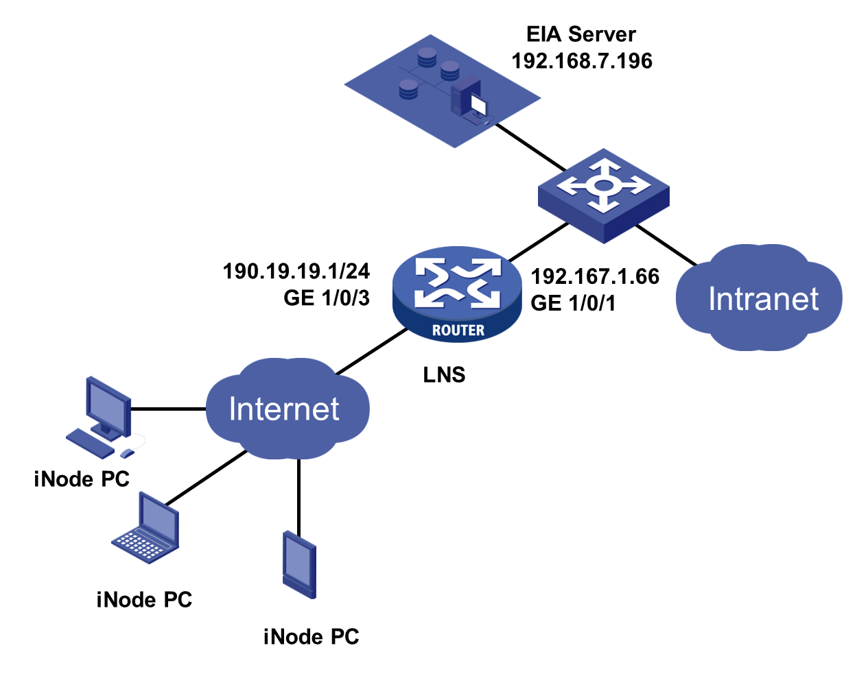
Network configuration
Configure the network as shown in Figure 1.
To identify the northbound service virtual IP of the EIA server in a cluster deployment:
1. Enter https://ip_address:8443/matrix/ui in the address bar of the browser to open the Matrix page. ip_address represents the northbound service virtual IP or node IP address.
2. On the top navigation bar, click DEPLOY.
3. From the left navigation pane, select Clusters.
4. Click the Cluster Parameters tab. Use the IP address in the Northbound Service Virtual IP field as the IP address of the EIA server.
|
|
NOTE: The northbound service virtual IP (10.114.117.164) in the screenshot is for illustration only. It differs from the one used in this example. |
Software versions used
This configuration example was created and verified on the following software:
|
Role |
Platform |
Software version |
|
Authentication server |
EIA |
EIA (E6205) |
|
L2TP device |
H3C SecPath F5040 |
Version 7.1.064 |
|
Client |
iNode |
iNode PC 7.3 (E0513) |
Analysis
The key points for VPN access are as follows:
· The EIA server acts as a RADIUS server to authenticate users' identities.
· The LNS controls whether end users can access the intranet.
· The LNS controls user access to the intranet based on the access control policies deployed by EIA.
Procedures
Configuring the LNS
Configure an L2TP tunnel and IPsec encryption on the LNS. In L2TP IPsec VPN access, the L2TP tunnel is a dedicated channel for data transmission, while the IPsec tunnel encrypts the data transmitted in the tunnel. Configure the L2TP tunnel to use an AAA server for authentication, specifically the EIA server. This configuration example was created and verified on H3C SecPath F5040).
Configuring the LNS (main mode)
1. Enable DHCP in system view.
<H3C>system-view
System View: return to User View with Ctrl+Z.
[H3C]dhcp enable
2. Specify the authentication server and accounting server as the EIA server. Include domain names in the usernames sent to the RADIUS server.
[H3C]radius scheme hz14597
New RADIUS scheme
[H3C-radius-hz14597]primary authentication 192.168.7.196 1812 [H3C-radius-hz14597]primary accounting 192.168.7.196 1813
[H3C-radius-hz14597]key authentication simple password
[H3C-radius-hz14597]key accounting simple password
[H3C-radius-hz14597]user-name-format with-domain
[H3C-radius-hz14597]quit
3. Create a domain named 14597. Specify scheme hz14597 for RADIUS authentication, authorization, and accounting of PPP users.
The name of the domain must be the same as the service suffix configured in "Adding an access service."
[H3C]domain 14597
[H3C-isp-14597]authentication ppp radius-scheme hz14597
[H3C-isp-14597]authorization ppp radius-scheme hz14597
[H3C-isp-14597]accounting ppp radius-scheme hz14597
[H3C-isp-14597]quit
[H3C]ip pool 1 200.1.1.2 200.1.1.100 //Create an address pool for VPN users.
4. Create interface Virtual-Template 145 as one end of the L2TP tunnel. The other end of the L2TP tunnel is the VPN vNIC of the PC. Configure CHAP authentication for VPN users in domain 14597 on the local end.
[H3C]interface Virtual-Template 145
[H3C-Virtual-Template145]ppp authentication-mode chap domain 14597
[H3C-Virtual-Template145]dhcp relay server-address 192.168.5.201 //Specify a DHCP server.
[H3C-Virtual-Template145]ip address 200.1.1.1 255.255.255.0 //Configure the IP address of the local end. For communication with the other end of the L2TP tunnel (VPN vNIC of the PC), make sure the IP is on the same subnet as the address pool of the vNIC but does not belong to the address pool.
[H3C-Virtual-Template145]remote address pool 1 //Assign an address pool in the VPN domain for VPN users.
[H3C-Virtual-Template145]quit
5. Enable L2TP and create L2TP group 14597 in LNS mode. Specify Virtual-Template 145 for receiving calls from an LAC. Configure the authentication key as 123456 in plain text.
[H3C]l2tp enable
[H3C]l2tp-group 14597 mode lns
[H3C-l2tp14597]allow l2tp virtual-template 145 remote iNode
[H3C-l2tp14597]tunnel password simple 123456
[H3C-l2tp14597]quit
6. Create an IPsec transform set named hz14597.
An IPsec transform set defines the security parameters for IPsec SA negotiation, including the security protocol, encryption algorithms, authentication algorithms, and encapsulation mode.
[H3C]ipsec transform-set hz14597 //Create an IPsec transform set named hz14597.
[H3C-ipsec-transform-set-hz14597]encapsulation-mode tunnel //Set the packet encapsulation mode to tunnel.
[H3C-ipsec-transform-set-hz14597]protocol ah //Specify the security protocol as AH.
[H3C-ipsec-transform-set-hz14597]ah authentication-algorithm md5 //Specify the authentication algorithm for AH as HMAC-MD5.
[H3C-ipsec-transform-set-hz14597]quit
7. Create IKE proposals.
You can configure multiple proposals at both ends of the tunnel. For tunnel establishment, make sure at least one proposal match at both ends.
[H3C]ike proposal 14597
[H3C-ike-proposal-14597]authentication-method pre-share //Specify pre-share as the authentication method.
[H3C-ike-proposal-14597]authentication-algorithm md5 //Specify the authentication algorithm as HMAC-MD5.
[H3C-ike-proposal-14597]encryption-algorithm 3des-cbc //Specify the encryption algorithm as 3DES-CBC.
[H3C-ike-proposal-14597]dh group1 //Specify the DH group as Group 1.
[H3C-ike-proposal-14597]sa duration 86400 //Set the IPsec SA lifetime to 86400 seconds. If the communicating peers are configured with different IKE SA lifetime settings, the smaller setting takes effect. Use the default setting (86400 seconds) as a best practice.
[H3C-ike-proposal-14597]quit
8. Create an IKE keychain named hz14597, and specify 123 in plain text as the pre-shared key to be used with the remote peer on subnet 190.19.19.0/24.
[H3C]ike keychain hz14597
[H3C-ike-keychain-hz14597]pre-shared-key address 190.19.19.0 24 key simple 123
[H3C-ike-keychain-hz14597]quit
9. Configure an IKE profile.
[H3C]ike profile hz14597 //Create an IKE profile named hz14597.
[H3C-ike-profile-hz14597]exchange-mode main //Specify the IKE phase 1 negotiation mode as the main mode.
[H3C-ike-profile-hz14597]local-identity address 190.19.19.1 //Configure the local ID with the identity type as IP address and the value as 190.19.19.1.
[H3C-ike-profile-hz14597]match remote identity address range 190.19.19.2 190.19.19.254 //Configure a peer ID with the identity type as IP address and the address range as 190.19.19.2 to 190.19.19.254. This address range is the one of the iNode client, and only IPs in this range can perform IKE negotiation.
[H3C-ike-profile-hz14597]keychain hz14597 //Specify IKE keychain hz14597 for the IKE profile.
[H3C-ike-profile-hz14597]proposal 14597 //Specify IKE proposal 14597 for the IKE profile.
[H3C-ike-profile-hz14597]quit
10. Configure IPv4 advanced ACL 3145 to identify the traffic to be protected by IPsec.
[H3C]acl advanced 3145
[H3C-acl-ipv4-adv-3145]rule 0 permit ip
[H3C-acl-ipv4-adv-3145]quit
11. Create an IPsec policy template named tempolicy. Specify IPsec transform set hz14597, IKE profile hz14597, and ACL 3145 for the IPsec policy template.
[H3C]ipsec policy-template tempolicy 1
[H3C-ipsec-policy-template tempolicy-1]transform-set hz14597
[H3C-ipsec-policy-template tempolicy-1]ike-profile hz14597
[H3C-ipsec-policy-template tempolicy-1]security acl 3145
[H3C-ipsec-policy-template tempolicy-1]quit
12. Create an IKE-based IPsec policy entry named vpnpolicy by using IPsec policy template tempolicy.
[H3C]ipsec policy vpnpolicy 1 isakmp template tempolicy
13. Configure GigabitEthernet 1/0/3 to operate in Layer 3 mode. Assign an IP address, enable the DHCP relay agent, and apply IPsec policy to the interface.
[H3C]interface GE1/0/3
[H3C-GigabitEthernet1/0/3]port link-mode route
[H3C-GigabitEthernet1/0/3]ip address 190.19.19.1 255.255.255.0
[H3C-GigabitEthernet1/0/3]dhcp select relay
[H3C-GigabitEthernet1/0/3]dhcp relay server-address 192.168.5.201
[H3C-GigabitEthernet1/0/3]ipsec apply policy vpnpolicy
Configuring the LNS (aggressive mode)
In Windows Vista and later operating systems, in VPN authentication, you must configure NAT traversal and ESP mode, even though a NAT device is not required in the actual network. For NAT traversal, you must configure the aggressive mode.
Configure the device as described in "Configuring the LNS (main mode)" except that you must configure the IPsec transform set and IKE profile as follow:
1. Configure an IKE profile:
# Create an IKE profile named Han.
[H3C]ike profile Han
# Specify the IKE phase 1 negotiation mode as the aggressive mode.
[H3C-ike-profile-Han]exchange-mode aggressive
# Set the local identity to FQDN name LNS.
[H3C-ike-profile-Han]local-identity fqdn LNS
# Configure a peer ID with the identity type of FQDN name and the value of LAC.
[H3C-ike-profile-Han]match remote identity fqdn LAC
# Specify IKE keychain hz14597 for the IKE profile.
[H3C-ike-profile-Han]keychain hz14597
# Specify IKE proposal 14597 for the IKE profile.
[H3C-ike-profile-Han]proposal 14597
[H3C-ike-profile-Han]quit
2. Configure an IPsec transform set:
# Create an IPsec transform set named han1.
[H3C]ipsec transform-set han1
# Specify the encapsulation mode as tunnel.
ESP provides both authentication and encryption, ensuring higher security.
[H3C-ipsec-transform-set-han1]encapsulation-mode tunnel
# Specify the security protocol as ESP.
[H3C-ipsec-transform-set-han1]protocol esp
# Specify the authentication algorithm as HMAC-MD5.
[H3C-ipsec-transform-set-han1]esp authentication-algorithm md5
# Specify the encryption algorithm as DES-CBC.
[H3C-ipsec-transform-set-han1]esp encryption-algorithm des-cbc
[H3C-ipsec-transform-set-han1]quit
Configuring the EIA server
Adding an access device
Add the LNS as an access device. You must add an access device to the EIA server before the EIA server can work with the access device for authentication.
To add a device:
1. Log in to IMC and click the Automation tab.
2. From the navigation pane, select User > Access Service > Access Device Management.

3. Click Add.
Figure 3 Adding an access device

4. Click Add IPv4 Device in the Device List area. In the window that opens, enter the IP address of the access device in the Device IP field, and then click Confirm.
Follow these restrictions and guidelines when adding the access device:
¡ If the RADIUS scheme contains a NAS IP specified by using the nas-ip command for the access device, specify that IP address on the EIA server.
¡ If the RADIUS scheme does not contain a NAS IP, specify the IP address of the Layer 3 Ethernet interface or VLAN interface that connects the access device to the EIA server.
Figure 4 Manually entering the IP address of the access device

5. Configure the following common parameters:
¡ Authentication Port: Specify a port number for EIA to listen for RADIUS authentication packets. The authentication port must be the same as that specified in the RADIUS scheme on the access device. By default, the authentication port is 1812 on the EIA server and the access device.
¡ Accounting Port: Specify a port for EIA to listen for RADIUS accounting packets. The accounting port must be the same as that specified in the RADIUS scheme on the access device. By default, the accounting port is 1813 on the EIA server and the access device.
|
|
NOTE: You must use the EIA server to provide both authentication and accounting services. You cannot use the EIA server as the authentication server and another server as the accounting server. |
¡ Shared Key/Confirm Shared Key: Specify a shared key and confirm it. The access device and the EIA server use the shared key to validate each other. The shared key must be the same as that configured in the RADIUS scheme on the access device. You only need to enter the shared key once if you selected Plaintext for the Displays Key in field in system parameter settings on the Automation > User > Service Parameters > Access Parameters > System Settings page.
¡ Use the default settings for other parameters.
Figure 5 Configuring the common parameters

6. Click Confirm. On the access device management page, verify that the access device has been added to the access device list.
Figure 6 Verifying that the access device has been added

Adding an access policy
To add an access policy:
1. On the top navigation bar, click Automation.
2. From the navigation pane, select User > Access Service.
3. Click the Access Policy tab.
Figure 7 Access policy management page

4. Click Add. On the page that opens, configure the access policy as needed. In this example, because no access control is required, you only need to enter an access policy name and use the default settings for other parameters.
Figure 8 Adding an access policy

|
|
NOTE: To deploy authorization information, make sure the attributes are supported on the device. For the authentication binding information to take effect, you must configure the corresponding information in the RADIUS attributes on the device. In this example, you do not need to deploy authorization information. The default settings apply. |
5. Click Confirm. On the access policy management page, verify that the access policy has been added to the access policy list.
Figure 9 Verifying that the access policy has been added

Adding an access service
An access service is a collection of policies for user authentication and authorization. This example adds a simple access service that does not contain any access control settings.
To add an access service:
1. On the top navigation bar, click Automation.
2. From the navigation pane, select User > Access Service.
Figure 10 Access service management page

3. Click Add.
Figure 11 Adding an access service

Configure the following parameters:
¡ Service Name: Enter a service name. Make sure the name is unique on the EIA server.
¡ Service Suffix: Enter a service suffix, which identifies the name of the domain to be used for user authentication. The service suffix, authentication username, authentication domain, and the device's RADIUS scheme command are closely related to each other. For more information about the matrix of these elements, see Table 1.
¡ Default Access Policy: Specify an access policy as the default access policy.
¡ Default Internet Access Policy: Specify the Internet access policy applied to users in access scenarios that are not included in the service.
¡ Use the default settings for other parameters.
|
Authentication username |
Authentication domain |
Device's RADIUS scheme command |
Service suffix on EIA |
|
X@Y |
Y |
user-name-format with-domain |
Y |
|
user-name-format without-domain |
No suffix |
||
|
X |
[Default Domain] Default domain on the device |
user-name-format with-domain |
[Default Domain] |
|
user-name-format without-domain |
No suffix |
4. Click Confirm. On the service management page, verify that the access service has been added to the access service list.
Figure 12 View the added access services for more information.

Adding an access user
You must configure the identification information of an access user on EIA, including the username, password, access service, and other information.
To add an access user:
1. On the top navigation bar, click Automation.
2. From the navigation pane, select User > Access User.

3. Click Add.
Figure 14 Adding an access user

4. Configure the access information and access service:
¡ Account Name: Enter an account name to uniquely identify the access user.
¡ Password/Password Confirm: Enter the password for authentication and enter the password again for confirmation.
¡ Access Service: Select an added access service.
¡ Use the default settings for other parameters.
5. Click Confirm. On the access user management page, verify that the added access user has been added to the access user list.
Figure 15 Verifying that the access user has been added

Verifying the configuration
Verify that the user can pass L2TP IPsec VPN authentication by entering the configured username and password on the iNode PC client.
Installing an iNode client
Install an iNode PC client with the L2TP IPsec VPN function.
|
|
NOTE: The EIA server is compatible with all versions of iNode clients. You can install an iNode client as needed. |
Performing L2TP IPsec VPN connection
1. On the homepage of the iNode PC client, select L2TP IPsec VPN connection.

2. In the L2TP IPsec VPN connection area that expands, click More, and then select Properties.
3. Configure basic settings.
Make sure the basic settings are consistent with the configurations on the LNS.

4. Click Advanced at the bottom right of the page. On the window that opens, configure advanced properties for the connection according to the specified negotiation mode (main mode or aggressive mode).
¡ If the main mode is used, configure the settings as shown in Figure 18, Figure 19, and Figure 20.
¡ If the aggressive mode is used, configure the settings as shown in Figure 18, Figure 21, and Figure 22.

· In main mode:


· In aggressive mode:


Performing L2TP IPsec VPN authentication
1. Enter the username and password, and then click Connect.

2. Verify that the L2TP IPsec VPN connection has been established.
