| Title | Size | Downloads |
|---|---|---|
| 04-H3C EIA Portal Authentication (IPv4) with NAT Traversal Configuration Example-book.pdf | 2.01 MB |
- Related Documents
-
| Title | Size | Download |
|---|---|---|
| book | 2.01 MB |
H3C EIA Portal Authentication (IPv4) with NAT Traversal
Configuration Examples
Software version: EIA (E0215P06)
Document version: 5W103-20240226
Copyright © 2024 New H3C Technologies Co., Ltd. All rights reserved.
No part of this manual may be reproduced or transmitted in any form or by any means without prior written consent of New H3C Technologies Co., Ltd.
Except for the trademarks of New H3C Technologies Co., Ltd., any trademarks that may be mentioned in this document are the property of their respective owners.
The information in this document is subject to change without notice.
Contents
Example: Configuring IPv4 portal authentication with NAT traversal
Configuring the portal service
Configuring a RADIUS scheme and an authentication domain (for communication with the AAA server)
Configuring portal authentication (for communication with the portal server)
Introduction
The following information provides an example of configuring IPv4 portal authentication for access users that traverse NAT.
Feature usage guidelines
Application scenarios
The authentication server (EIA server) is deployed on the public network. Internal users traverse the NAT device of the ISP network to perform portal authentication.
Restrictions and guidelines
· The access device configuration and NAT device configuration are subject to the configurations on the actual access and NAT devices.
· With NAT protection for internal user security, the EIA message distribution function is not available. Other EIA functions are not affected.
Prerequisites
· The access device must support the portal protocol.
· The EIA component is deployed on the EIA server.
Example: Configuring IPv4 portal authentication with NAT traversal
Network configuration
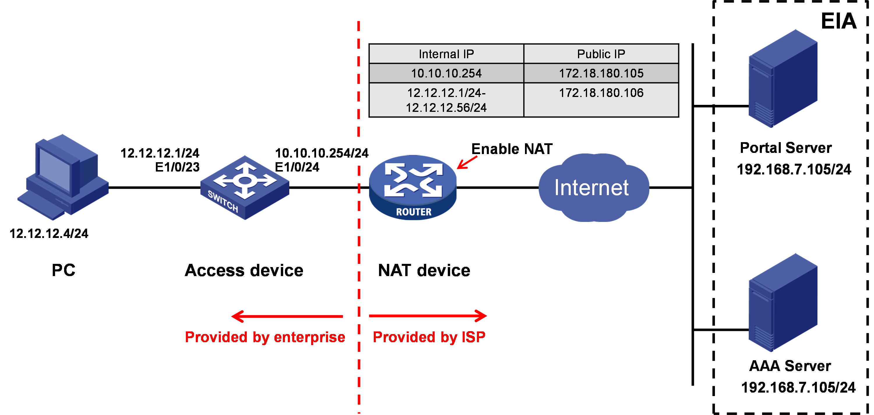
As shown in Figure 1, the EIA server of an enterprise is deployed on the public network provided by the ISP. The EIA server provides portal and AAA services. A NAT device is deployed between the enterprise internal network and the EIA server to translate addresses. The PC in the internal network uses an iNode client to perform portal authentication to access the network. Enable portal authentication on the access device, which is the switch nearest to the PC.
Software versions used
This configuration example was created and verified on the following software versions:
· The iNode client runs iNode PC 7.3 (E0558).
· The access device runs H3C S5820V2-54QS-GE Comware Software, Version 7.1.045.
· The NAT device runs H3C SecPath F5020 Comware Software, Version 7.1.064.
· The EIA server runs EIA (E0215P06).
To view the IP address of the EIA server, use the following procedure:
|
|
NOTE: · In a cluster deployment environment, use the northbound service virtual IP address instead of the node IP address as the IP address of the EIA server. · This example uses EIA server IP address 10.114.117.195 for illustration. |
a. Enter https://ip_address:8443/matrix/ui in the address bar of the browser to open the Matrix page. ip_address represents the northbound service virtual IP address or node IP address.
b. On the top network navigation bar, click DEPLOY.
c. From the navigation pane, select Clusters.
d. Click the Cluster Parameters tab, and view the IP address in the VIP field.
Figure 2 Viewing IP address of the EIA server

Configuring the EIA server
Configure the following items on the EIA server:
· Access device.
· Access policy.
· Access service.
· Access user.
· Portal service.
Adding an access device
Add an access device to the EIA server for collaboration and management.
To add an access device to the EIA server:
1. On the top network navigation bar, click Automation.
2. From the navigation pane, select User > Access Service, and then click Access Device Management to open the Access Device page.
Figure 3 Access device configuration page

3. Click Add.
Figure 4 Adding the access device

4. Click Add IPv4 Device. In the window that opens, enter the IP address of the access device (172.18.180.105) in the Device IP field, and then click Confirm.
¡ If you use the nas-ip command to specify the NAS IP address when you configure the RADIUS scheme on the access device, the IP address of the access device on the EIA server must be the after-NAT public IP for the NAS IP address.
¡ If you do not use the nas-ip command to specify the NAS IP address on the access device, the IP address of the access device on the EIA server must be the IP address of the device interface connected to the EIA server (or the IP address of the VLAN interface where the interface connected to the EIA server resides).
Figure 5 Manually adding the access device

5. Configure public parameters:
¡ Authentication Port: Specify the port for monitoring the authentication packets. The shared key on the EIA server must be the same as that configured on the access device. The default port is 1812 on both the EIA server and the access device.
¡ Accounting Port: Specify the port for monitoring the accounting packets. The accounting port on the EIA server must be the same as that configured on the access device. The default port is 1813 on both the EIA server and the access device.
|
|
IMPORTANT: The EIA server supports acting as both the authentication and accounting servers. You cannot use the EIA server as the authentication server and another server as the accounting server. |
¡ Service Type: Select a service type carried by the access device. Only LAN access service and device management service are supported. For the device to support both LAN access service and device management services, select Unlimited.
¡ Access Device Type: Select the vendor and type of the access device. Available options include Standard, EIA system predefined vendors and types, and administrator-defined vendors and types. You can select Standard for any device that supports standard RADIUS protocol. The system predefined vendors and types include H3C(General), 3COM(General), HUAWEI(General), CISCO(General), RG(General), HP(MSM), HP(Comware), MICROSOFT(General), JUNIPER(General), HP(ProCurve), and ARUBA(General).
¡ Service Group: Select the service group to which the access device belongs. You can add access devices to different service groups for hierarchical management.
¡ Shared Key/Confirm Shared Key: Enter the shared key in the Shared Key field and re-enter the key in the Confirm Shared Key field for confirmation. The shared key is used for secure communication between the server and the access device. The shared key on the EIA server must be the same as that configured on the access device.
If you select Plaintext in the Displays Key in field on the Automation > User > Service Parameters > Access Parameters > System Settings page, enter the shared key in the Shared Key field. You do not need to confirm the shared key in this case.
¡ Access Location Group: Select an access device group for the access device. Available options include the existing access device groups in EIA and None. The access device group information is one of the conditions used to distinguish endpoints.
In this example, you only need to enter and confirm the shared key hello. Other parameters use the default settings.
Figure 6 Public parameter settings

6. Click Confirm. The operation result page is displayed. Return to the access device configuration page, where you can view the access device newly added.
Adding an access policy
In order to configure an access service, you must first configure an access policy. If you do not need enforce access control, you can configure an access policy without any access control settings.
To add an access policy:
1. On the top network navigation bar, click Automation.
2. From the navigation pane, select User > Access Service, and then click Access Policy to open the Access Policy page.
Figure 7 Access policy configuration page

3. Click Add. On the page that opens, configure the access policy as needed. If access control is not needed, enter the access policy name, and use the default settings for other parameters.
Figure 8 Adding the access policy

Access policy parameters:
¡ Access Period: After you select an access period policy, a user using the rule is allowed to access the network only in the time range customized in the access period policy.
¡ Allocate IP: Specify whether to assign IP addresses to users.
¡ Upstream Rate (Kbps)/Downstream Rate (Kbps): Specify the maximum upstream rate and downstream rate for the access policy.
¡ Priority: Specify the priority of the packets to be forwarded in network congestion. A smaller value indicates a higher priority. This value should be selected from the priority values supported by the device. Otherwise, the endpoint user might fail to access the network.
¡ Authentication Type/Subtype: Select an EAP authentication type. During EAP authentication, the RADIUS server deploys this EAP authentication type preferentially to the client. Options include EAP-MD5, EAP-TLS, EAP-TTLS, and EAP-PEAP. When EAP-TTLS or EAP-PEAP is selected, select EAP-MSCHAPv2, EAP-MD5, or EAP-GTC as the subtype.
- EAP-MD5: Initiates EAP authentication by using the CHAP authentication mechanism.
- EAP-TLS: Certificate-based identification authentication, which needs to deploy the PKI to manage certificates. The server and client use the certificate for identity authentication. If authentication succeeds, the two sides negotiate for a shared key, session ID, cryptographic specifications (cipher, compression, and data integrity check) to set up a reliable communication channel. EAP-TLS uses the TLS protocol to implement identity authentication between the client and EIA. It uses the session ID for fast reauthentication, which greatly simplifies the authentication process. It also supports fragmentation of large TLS packets.
- EAP-TTLS: Initiates subauthentication on the security channel set up by TLS authentication between the client and EIA. The authentication method protects the user identity and the negotiation process of EAP authentication. Over the TLS channel, EIA can initiate EAP or non-EAP authentication. EAP authentication can be EAP-MSCHAPv2, EAP-MD5, or EAP-GTC. Non-EAP authentication can be MSCHAPv2 or PAP. If EAP-TTLS is selected as the preferred EAP type for an access policy, you must select an EAP subtype. However, EIA always uses the same certificate authentication type as the setting on the user endpoint, and the actual authentication type can be non-EAP.
- EAP-PEAP: Initiates EAP authentication on the security channel set up by TLS authentication between the client and EIA. The authentication method protects the user identity and the negotiation process of EAP authentication. EAP authentication can be EAP-MSCHAPv2, EAP-MD5, or EAP-GTC.
¡ EAP Auto Negotiate: Automatic negotiation of EAP authentication types when the EAP authentication type configured on the client and the preferred EAP type do not match. When Enable is selected, EIA permits the authentication request from the client without considering the EAP type configured on the client. When Disable is selected, EIA rejects the authentication request of the client if the EAP authentication type configured on the client and the preferred EAP type on EIA do not match.
¡ Maximum Online Duration for a Logon (Minutes): Maximum duration an authenticated access user that uses the access policy can be online. When this field is empty, the online duration is not limited. To specify this field, enter an integer in the range of 1 to 1440. If the online duration for an access user exceeds the specified value, EIA logs off the user.
¡ Deploy VLAN: Specify the VLAN to deploy to the user. After passing authentication, the user can access resources in the specified VLAN only. If the type of the access device is H3C(General), Huawei(General), HP(Comware), or 3Com(General), you can enter a VLAN ID or VLAN name. EIA considers any integer in the range of 1 to 4094 as a VLAN ID and deploys it as an integer-type string to the access device. Any other character string is considered as a VLAN name and deployed to the access device as a VLAN NAME string. If the access device is none of the previous types, EIA always deploys the entered value to the access device as a VLAN NAME string. On the access device, configure the VLAN assignment mode as integer or string accordingly.
¡ Deploy Address Pool: Enter an address pool name. EIA deploys the address pool name to the access device for IP address assignment to users. For successful address assignment, make sure an address pool with the same name exists on the access device.
¡ Deploy User Profile: Deploy the user profile name to the device to perform the QoS functions based on users. This function takes effect only when the deployed user profile has been configured on the device.
¡ Deploy User Group: Deploy the user group to which the user belongs to the device after the user passes authentication. You can enter multiple user groups, separated by semi-colon (;). This function takes effect only when EIA works with an SSL VPN device or collaborates with ACG 1000.
¡ Deploy ACL: Deploy the ACL to users.
¡ Offline Check Period (Hours): EIA issues this parameter to the device after a mute terminal passes authentication. The device checks whether the mute terminal is offline at the intervals. If no packet is received from a mute terminal within the interval, the device terminates the connection with the mute terminal and sends a use offline notification to the RADIUS server. If you leave this field empty, the default applies. A value of 0 means that offline check will not be performed. This parameter must be an integer in the range of 0 to 596523, and applies only to mute terminals.
¡ Authentication Binding Information: EIA cooperates with the access device to check the binding information for each user account to be authenticated, including the IP address, port VLAN. QinQ (or double VLAN tags), and SN of the access device, and the IP address, MAC address, IMSI, IMEI, wireless user SSID and the hard disk serial number of the user terminal. The iNode client cooperates with the policy server to check the following binding information for the user: user IP address, MAC address, computer name, computer domain, logon domain and the hard disk serial number. Among these items, user MAC address and IMSI are mutually exclusive and cannot be bound at the same time. The binding requirements can be set for a service which contains the binding policy. If no requirements are set for such service, auto learning is adopted. Auto-learning is to bind the parameters used for the first login. For example, you set user IP address binding without specifying any IP address. If the user uses 10.100.10.10 for the first login through the service, it must always use the IP address for the future authentication.
- Control Hard Disk Serial Number: With this function enabled, EIA checks the hard disk serial number of an access user using this service when the user attempts to come online. If the serial number is permitted, the user is allowed to come online. Otherwise, the access is denied. If EIA cannot obtain the hard disk serial number, it allows the user to come online. This feature must work with the iNode PC client.
- Enable SSID Access Control: When you enable this feature and select Permit from the SSID Filter list, EIA maintains an SSID allowlist. Users can access the network when they connect to an SSID on the SSID Access Control list. When you enable this feature and select Deny from the SSID Filter list, EIA maintains an SSID denylist. Users cannot access the network when they connect to an SSID on the SSID Access Control list. This feature must work with the iNode PC client. The client receives the SSID access control configuration from EIA and saves the configuration to the PC. The configuration also applies to the Windows built-in 802.1X application.
|
|
NOTE: To deploy authorization information, make sure the attributes are supported on the device. For the authentication binding information to take effect, you must configure the corresponding information in the RADIUS attributes on the device. In this example, you do not need to deploy authorization information. The default settings apply. |
4. Click Confirm. View the added access policy in the access policy list.
Figure 9 Viewing the added access policy

Adding an access service
An access service is a collection of policies for user authentication and authorization.
To add an access service:
1. On the top network navigation bar, click Automation.
2. From the navigation pane, select User > Access Service.
Figure 10 Access service management page

3. Click Add. On the page that opens, enter the service name and service suffix, specify the default access policy, and use the default settings for other parameters.
Figure 11 Adding an access service

Access service parameters:
¡ Service Name: Specify the service name. A service name uniquely identifies an access service in EIA.
¡ Service Suffix: Specify the service suffix. The service suffix, authentication username, authentication domain, and the device's RADIUS scheme command are closely related to each other. For more information about the matrix of these elements, see Table 1.
¡ Default Access Policy: Specify the added access policy as the default access policy.
¡ Security Group: Specify the security group.
¡ Sub Security Group: Specify the security subgroup.
¡ Default Proprietary Attribute Assignment Policy: If a user using the service does not match an access device group when the user accesses the network, the system deploys proprietary attributes to the access device according to the configuration of the default proprietary attribute assignment policy.
¡ Default Max. Devices for Single Account: Specify the maximum number of endpoints that can be bound to the access user when the user's access scenario matches none of the access scenarios in the service assigned to the user. This parameter appears only when the EIP component is deployed. EIA checks the maximum number of bound endpoint devices for a single account in the following order:
- Matched access scenario: Checks the number of bound endpoint devices against the maximum number limit specified in the scenario. If the number reaches the limit, EIA denies the user authentication.
- Scenarios in all services: Checks the number of bound endpoint devices in scenarios of all assigned services for the account. If the number reaches the value of Max. Devices for Single Account specified in user endpoint settings on the Automation > User > Service Parameters > Access Parameters > System Settings page, EIA denies the user authentication.
¡ Default Max. Number of Online Endpoints: Specify the maximum number of endpoints that can be simultaneously used for network access by the access user when the user's access scenario matches none of the access scenarios in the service assigned to the user.
¡ Daily Max. Online Duration: Total duration in a day that an account can access the network by using the service. When the limit is reached, the account is forced offline and is unable to access the network in the day. This parameter is an integer in the range of 0 to 1440 minutes. A value of 0 means not limited.
¡ Description: Brief description for the service.
|
Authentication Username |
Authentication Domain |
Command in Device's RADIUS Scheme |
Service Suffix |
|
X@Y |
Y |
user-name-format with-domain |
Y |
|
user-name-format without-domain |
No suffix. |
||
|
X |
[Default Domain] |
user-name-format with-domain |
[Default Domain] |
|
user-name-format without-domain |
No suffix. |
4. Click Confirm. View the added access service in the access service list.
Figure 12 Viewing the added access service

Adding an access user
An access user defines the credentials used by the user to access network resources, including the account name, password, and used service.
To add an access user:
1. On the top network navigation bar, click Automation.
2. From the navigation pane, select User > Access User.
Figure 13 Access user configuration page

3. Click Add. On the page that opens, configure the access user parameters.
Figure 14 Adding an access user

Access user parameters:
¡ User Name/Identity Number: Specify the username and identity number of the access user.
¡ Account Name: Specify the account name for authentication. An account name uniquely identifies an access user in EIA.
¡ Password/Password Confirm: Enter the password for authentication and enter the password again for confirmation.
¡ Access Service: Select the previously added access service.
¡ Use the default settings for other parameters.
Figure 15 Access user parameter settings

4. Click Confirm. View the added access user in the access user list.
Figure 16 Viewing the added access user

Configuring the portal service
Configure the portal service for iNode clients to come online through portal authentication.
Perform the following tasks to configure the portal service:
· Configuring a portal server.
· Configuring a portal IP group.
· Configuring a portal device.
Configuring a portal server
1. On the top network navigation bar, click Automation.
2. From the navigation pane, select User > Access Service. Click Portal Service on the top right to open the Portal Server page.
Figure 17 Portal server configuration page

3. In the Advanced Information area, click Add next to Service Type List. On the page that opens, add a service type.
Figure 18 Adding a service type

Service type parameters:
¡ Service Type ID: The device determines the authentication mode according to the ID of the selected service type. Make sure the service type ID is the same as the service suffix of the added access service.
¡ Service Type: A service type ID is used by the device. Users might not understand what a service type ID means. You must enter a service type that is understandable to users for the service type ID. Service types will be displayed on the portal login page for users to select. This field can neither be null nor be identical with any existing service type. You can configure a maximum of 64 service types.
4. Click Confirm. View the added service type in the service type list.
Figure 19 Viewing the added service type

5. Click Confirm to complete portal server configuration.
Configuring a portal IP group
1. On the top network navigation bar, click Automation.
2. From the navigation pane, select User > Access Service, and then click Portal Service > Portal IP Group.
Figure 20 Portal IP group configuration page

3. Click Add. On the page that opens, add an IP group.

4. Configure the IP group as follows:
¡ IP Group Name—Enter the IP group name. This example uses natip.
¡ Start IP/End IP—Enter the start IP address and end IP address of the address segment. The system performs authentication on all endpoints in the address segment.
¡ Action—Select NAT.
¡ After-action Start IP/End IP—Enter the after-action start IP address and the after-action end IP address.
5. Click Confirm. View the added IP group in the IP group list.
Figure 22 Viewing the added IP group

|
|
NOTE: · The end IP must be higher than or equal to the start IP. · The start IP and end IP must be consistent with the internal IP addresses set on the NAT device. · The after-action start IP/end IP must be consistent with the NAT address pool settings on the NAT device. |
Configuring a portal device
1. On the top network navigation bar, click Automation.
2. From the navigation pane, select User > Access Service, and then click Portal Service > Portal Device.
Figure 23 Portal device configuration page

3. Click Add. On the page that opens, add a portal device.
Figure 24 Adding a portal device

Portal device parameters:
¡ Device Name: Name of the portal access device. In this example, AccessDev is used.
¡ Public IP: Public IP address of the access device. This IP address is the static IP mapped to the IP address used by the access device to connect to users. This example uses 172.18.180.106.
¡ Private IP: IP address used by the access device to connect to users. This example uses 12.12.12.1.
¡ Key/Confirm Key: Enter the key for authentication and enter the key again for confirmation. The key must be identical with the configuration on the device. In this example, world is used.
¡ Access method: Select the authentication mode used by the device. In this example, Directly Connected is used. In this access method, users use manually configured or DHCP-assigned IP addresses to access the portal server and the specified auth-free addresses. After passing the authentication, they can access other network resources.
¡ Use the default settings for other parameters.
4. Click Confirm. View the added portal device in the portal device list.
Figure 25 Viewing the added portal device

5. Click the Port Group
icon ![]() in the Operation column for the device.
in the Operation column for the device.
Figure 26 Port group configuration page

6. Click Add.

Port group parameters:
¡ Port Group Name: Specify the port group name. In this example, natport is used.
¡ Authentication Type: Specify the authentication type. In this example, CHAP is used.
¡ IP Group: Specify the previously added IP group natip.
¡ Default Authentication Page: Select PC – Default WEB Login(PC).
¡ NAT or Not: Select Yes.
¡ Use the default settings for other parameters.
7. Click Confirm. View the added port group in the port group list.
Figure 28 Viewing the added port group

Configuring the access device
The access device is used for packet exchange between the portal server and the AAA server. You need to configure RADIUS scheme, authentication domain, and portal features on the access device.
Configuring a RADIUS scheme and an authentication domain (for communication with the AAA server)
1. Create a RADIUS scheme named EIA.
[AccessDev]radius scheme EIA
2. Specify the AAA server as the authentication/accounting server. the listening port numbers are the same as those configured on EIA in "Adding an access device."
[AccessDev-radius-EIA]primary authentication 192.168.7.105 1812
[AccessDev-radius-EIA]primary accounting 192.168.7.105 1813
3. Configure the authentication and accounting keys, which must be the same as those configured on EIA in "Adding an access device."
[AccessDev-radius-EIA]key authentication simple hello
[AccessDev-radius-EIA]key accounting simple hello
[AccessDev-radius-EIA]nas-ip 10.10.10.254
4. iNode authentication username, domain, and EIA service suffix configuration matrix is described in Table 1. This example uses the first configuration combination.
[AccessDev-radius-EIA]user-name-format with-domain
[AccessDev-radius-EIA]quit
5. create an ISP domain named nat. The domain name must be the same as the service suffix in "Adding an access service."
[AccessDev]domain nat
6. Configure the ISP domain to use RADIUS scheme EIA for authentication, authorization, and accounting for portal users.
[AccessDev-isp-nat]authentication portal radius-scheme EIA
[AccessDev-isp-nat]authorization portal radius-scheme EIA
[AccessDev-isp-nat]accounting portal radius-scheme EIA
[AccessDev-isp-nat]quit
Configuring portal authentication (for communication with the portal server)
1. Create portal authentication server named EIA, configure its IP address as the IP address of the EIA server, and set the shared key as world. The share key must be the same as that configured in "Configuring a portal device."
[AccessDev]portal server EIA
[AccessDev-portal-server-EIA]ip 192.168.7.105 key simple world
[AccessDev-portal-server-EIA]quit
2. Configure portal Web server EIA. Make sure the URL is the same as that configured on EIA in Portal Page field (see Figure 17).
[AccessDev]portal web-server EIA
[AccessDev-portal-websvr-EIA] url http://192.168.7.105:9092/portal
[AccessDev-portal-websvr-EIA]quit
3. Assign interface Ethernet 1/0/23 to VLAN 12.
[AccessDev]interface Ethernet1/0/23
[AccessDev-Ethernet1/0/23]port access vlan 12
[AccessDev-Ethernet1/0/23]port link-mode bridge
4. Enable direct portal authentication on VLAN-interface 12 where Ethernet 1/0/23 resides. Users access the network through this interface must pass portal authentication to use network resources.
[AccessDev]interface Vlan-interface12
[Device-Vlan-interface12]ip address 12.12.12.1 255.255.255.0
[Device-Vlan-interface12]portal enable method direct
[Device-Vlan-interface12]portal apply web-server EIA
[Device-Vlan-interface12]portal bas-ip 12.12.12.1
[Device-Vlan-interface12]portal domain nat
[Device-Vlan-interface12]quit
Configuring the NAT device
The access device must traverse the NAT device to communicate with the EIA server. You must configure and apply a NAT address pool, configure an internal server, and map some IP addresses of the access device to the public network addresses.
1. Configure ACL 3000 to define the internal address range to be NATed.
[NATDev]acl advanced 3000
2. Configure ACL rules to permit internal IP addresses in 10.10.10.0/24 and 12.12.12.0/24 to be NATed.
[NATDev-acl-adv-3000]rule 0 permit ip source 10.10.10.0 0.0.0.255
[NATDev-acl-adv-3000]rule 1 permit ip source 12.12.12.0 0.0.0.255
[NATDev-acl-adv-3000]rule 1000 deny ip
[NATDev-acl-adv-3000]quit
3. Configure an NAT address group and add public addresses to it.
[NATDev]nat address-group 0
[NATDev-address-group-0]address 172.18.180.105 172.18.180.106
[NATDev-address-group-0]quit
4. Assign interface GigabitEthernet 1/0 to VLAN 180.
[AccessDev]interface GigabitEthernet 1/0
[NATDev-GigabitEthernet1/0]port link-mode bridge
[NATDev-GigabitEthernet1/0]port access vlan 180
5. On VLAN-interface 180 that is connected to the public network, apply ACL 3000 and NAT address group 0. Then, packets sourced from subnet 10.10.10.0/24 and 12.12.12.0/24 and destined for the public network are NATed with the IP addresses in NAT address group 0. Portal authentication use UDP packets. Configure a NAT server mapping to permit portal authentication packet exchange.
[NATDev]interface Vlan-interface180
[NATDev-Vlan-interface180]ip address 172.18.180.1 255.255.255.0
[NATDev-Vlan-interface180]nat outbound 3000 address-group 0
[NATDev-Vlan-interface180]nat server protocol udp global 172.18.180.106 2000 inside 12.12.12.1 2000
[NATDev-Vlan-interface180]nat static enable
6. Map the access device's interface IP connected to the NAT device to a public IP address.
[NATDev]nat static outbound 10.10.10.254 172.18.180.105
7. Map the access device's interface IP connected to the user client to a public IP address.
[NATDev]nat static outbound 12.12.12.1 172.18.180.106
Verifying the configuration
Perform portal authentication by using an iNode PC client and a Web page. Verify that the portal authentication can succeed and the user has traversed NAT to come online.
Using an iNode client to log in
1. Open the iNode PC client, and select Portal connection.
2. Click the Refresh icon ![]() next
to the Server field. The iNode client automatically obtains portal server
information and populates the information in the Server field.
next
to the Server field. The iNode client automatically obtains portal server
information and populates the information in the Server field.
Figure 29 Obtaining portal server information

3. Enter username and password, select the NAT service type, and then click Connect. Portal authentication starts.
Figure 30 Portal authentication page

4. View the portal authentication result. The following page displays after the portal authentication succeeds.
Figure 31 Portal authentication success page

Using a Web page to log in
1. Open a browser. If you perform authentication for the first time, you can enter any address in the address bar, and you will be redirected to the portal authentication page.
Figure 32 Portal authentication page

2. Enter the username and password, and select the NAT service type, and then click Log In.
Figure 33 Entering user information for authentication

3. View the authentication result. The following page displays after the user passes portal authentication successfully.
Figure 34 Authentication success page

Viewing online user information
1. On top navigation bar, select Monitor.
2. From the navigation pane, select Monitor List > Online User.
3. Click the Local tab to view information about online users.
4. Click the Details icon for a user. On the detailed information page that opens, you can see that EIA can obtain the real IP address of the user and the IP address after NAT.
