- Released At: 14-03-2024
- Page Views:
- Downloads:
- Table of Contents
- Related Documents
-
H3C EAD Anti-Virus Management
Configuration Example
Document version: 5W100-20240314
Software version: EIA (E6204) and EAD (E6204)
Copyright © 2024 New H3C Technologies Co., Ltd. All rights reserved.
No part of this manual may be reproduced or transmitted in any form or by any means without prior written consent of New H3C Technologies Co., Ltd.
Except for the trademarks of New H3C Technologies Co., Ltd., any trademarks that may be mentioned in this document are the property of their respective owners.
The information in this document is subject to change without notice.
Introduction
EAD anti-virus management can perform centralized management over anti-virus software policies. The administrator first configures an anti-virus software policy on EAD, including the anti-virus software to be checked, software version, and virus library information. Then, the administrator configures a security policy to apply the anti-virus software policy. After an endpoint passes the authentication on the iNode client, the iNode client reports the anti-virus software information of the endpoint. If the anti-virus software version or virus library does not meet the requirements, the system kicks out or isolates the user based on the configured admission security level.
Feature usage guidelines
Application scenarios
Anti-virus management is applicable to enterprises, schools, or other environments that have endpoint and network security requirements. For example, configure anti-virus management for college networks with centralized deployment of anti-virus software or enterprise networks that prohibit access from endpoints without the specified anti-virus software installed.
Prerequisites
You have set up an anti-virus software server. For information about how to set up an anti-virus software server, see the documents provided by the anti-virus software vendor.
Example: Configuring anti-virus management
Network configuration
|
|
IMPORTANT: EAD deployment depends on the EIA component. To deploy EAD, deploy EIA first. |
As shown in Figure 2, configure the IP address of the EIA or EAD server as 192.168.0.87.
|
|
NOTE: · In a cluster deployment, specify the northbound service virtual IP as the IP address of the EIA or EAD server. Do not specify the node IP address of the EIA or EAD server. · The northbound service virtual IP (10.114.117.164) in the screenshot is for illustration only. It differs from the one used in this example. |
To obtain the northbound service virtual IP of the EIA or EAD server:
1. Enter https://ip_address:8443/matrix/ui in the address bar of the browser to open the Matrix page. ip_address represents the northbound service virtual IP or node IP address.
2. On the top navigation bar, click Deploy. From the navigation pane, select Clusters. Click the Cluster Parameters tab.
3. The displayed northbound service virtual IP is the IP address of the EIA or EAD server.
Figure 1 Obtaining the IP address of the EIA or EAD server


Software versions used
This configuration example was created and verified on the following platforms:
· EIA (E6204)
· EAD (E6204)
· H3C S5820V2-54QS-GE
· iNode PC 7.3 (E0585)
Procedures
To configure a comprehensive anti-virus management scheme, perform the following tasks:
1. Setting up an anti-virus software server
a. Configuring an anti-virus software policy
b. Configuring admission security levels
4. Configuring the access device
Setting up an anti-virus software server
For information about how to set up an anti-virus software server, see the documents provided by the anti-virus software vendor.
Configuring the EAD server
Configuring an anti-virus software policy
1. On the top navigation bar, click Automation. From the navigation pane, select Endpoint Business > Endpoint Security > Configuration Check Items > PC Security Software > Anti-Virus Software Policy.
Figure 3 Anti-virus software policy list

2. Click Add.
Figure 4 Configuring an anti-virus software policy

3. This document uses Kingsoft as an example. In the Windows area, select the checkbox in the Check column for Kingsoft.
Figure 5 Selecting the checkbox in the Check column for Kingsoft

Table 1 Parameter description
|
Parameter |
Description |
|
Check |
Select the checkbox in this column for anti-virus software to check the installation state of that software. |
|
Priority |
When much anti-virus software is installed, you can adjust the anti-virus software priority to change the check priority. When the iNode client identifies whether a system is installed with anti-virus software, it checks the software in the supported software list based on the priority configured in the policy. If much software is available, the iNode client checks only the software with the highest priority and reports its state to the policy server. Software with a lower priority is ignored. |
4. Click the edit icon in the Modify column for Kingsoft. On the page that opens, configure the check items as needed.
Figure 6 Anti-virus software settings

Table 2 Parameter description for anti-virus software settings
|
Parameter |
Description |
|
Second-Check Interval (s) |
When the first check fails, the check result is not reported. The iNode client performs another check after the specified interval and reports the check result. The value is in the range of 0 to 60 seconds. To report the check result immediately when the first check fails, set the value to 0. |
|
Version Check Mode |
Select a version check mode. If the obtained virus library version is in date format, the iNode client identifies whether the date format is valid. If the obtained virus library version is in dotted format, the iNode client identifies whether the dotted format is valid. |
|
Adaptation Period (in days) |
Specify the number of days within which the anti-virus engine version or virus library version used by the endpoint must have been updated, counting from the current date. To perform no check on the anti-virus software engine or virus library version, set the value to 0. |
5. Click OK to save the settings.
6. Click OK.
Figure 7 Anti-virus software policy configuration completed

|
|
NOTE: · An anti-virus software name represents a series of anti-virus software. An endpoint user can install any software in the series. · The internal interface and the Web interface of anti-virus software might be different. The version format displayed on the Web interface for some software might be different from that obtained by the iNode client. Configure the policy based on the version format obtained by the iNode client. For compatibility, select Date or dotted format for version check and configure both formats. |
Configuring admission security levels
Admission security levels are mainly used for allocating security modes for security check items that do not meet the security policy requirements. The security mode determines the method used for processing the user who has not passed the check.
On the top navigation bar, click Automation. From the navigation pane, select Endpoint Business > Endpoint Security > Admission Security Levels.
Figure 8 Admission security levels

Table 3 Admission security level parameter description
|
Parameter |
Description |
|
Monitor |
When the security check fails, the system only records the result in security logs only without isolating or informing the user. |
|
VIP |
When the security check fails, the system performs informing or remediation and records the result in security logs. |
|
Isolate |
When the security check fails, the system isolates the user, performs informing or remediation, and records the result in security logs. |
|
Kick Out |
When the security check fails, the system kicks out the user and records the result in security logs. |
|
Guest |
When the security check fails, the system informs the user, kicks out the user, and records the result in security logs. |
|
Block and Kick Out |
When the security check fails, the system adds the user to the blacklist, kicks out the user, and records the result in security logs. This mode does not support default security policy roaming. |
To add an admission security level, click Add. This document uses the predefined security levels.
Adding a security policy
Configure a security policy to control user security authentication. The operator deploys the policy based on the service binding method. When an access user applies for a service in a security policy, the user will be incorporated into the EAD security protection system defined by that security policy.
1. On the top navigation bar, click Automation. From the navigation pane, select Endpoint Business > Endpoint Security > Admission Security Policies.
Figure 9 Admission security policies

2. Click Add.
Figure 10 Adding an admission security policy
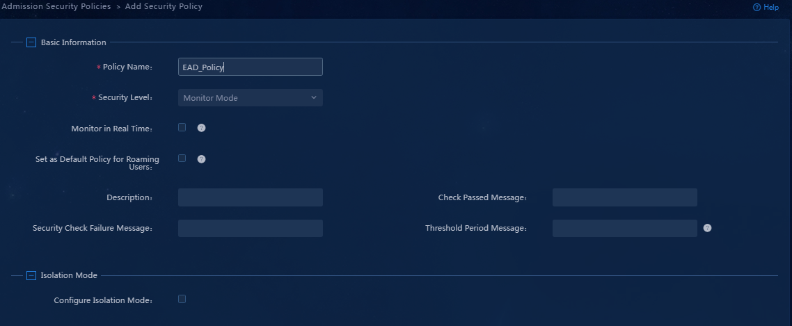
3. Enter a security policy name, select a security level, and select Check Anti-Virus Software. Configure the other parameters as needed.
Figure 11 Configuring the admission security policy

4. Click OK.
Figure 12 Admission security policy configuration completed

Configuring the EIA server
Adding an access device
You must add an access device to the EIA server before the EIA server can work with the access device for authentication.
To add an access device to the EIA server:
1. On the top navigation bar, click Automation. From the navigation pane, select User > Access Service. Click the Access Device Management tab.
Figure 13 Access device configuration page

2. Click Add.
Figure 14 Adding an access device

3. Click Add IPv4 Device in the Device List area. In the window that opens, enter the IP address of the access device in the Device IP field, and then click Confirm.
Follow these restrictions and guidelines when adding the access device:
¡ If the RADIUS scheme contains a NAS IP specified by using the nas ip command for the access device, specify that IP address on the EIA server.
¡ If the RADIUS scheme does not contain a NAS IP, specify the IP address of the Layer 3 Ethernet interface or VLAN interface that connects the access device to the EIA server.
Figure 15 Manually adding an access device

4. Configure the following common parameters:
¡ Authentication Port: Specify the RADIUS authentication service port on the EIA server. It must be the same as that specified on the access device. Typically, use the default service port 1812.
¡ Accounting Port: Specify the RADIUS accounting service port on the EIA server. It must be the same as that specified on the access device. Typically, use the default service port 1813.
|
|
IMPORTANT: You must use the EIA server to provide both authentication and accounting services. You cannot use the EIA server as the authentication server and another server as the accounting server. |
¡ Shared Key/Confirm Shared Key: Enter a shared key in the Shared Key field. If the system is configured to display keys in ciphertext, you must enter the key again in the Confirm Shared Key field for confirmation. In this example, enter movie.
The shared key is used for secure communication between the server and the access device.
The shared key specified on the EIA server must be the same as that specified on the access device.
You can enter the shared key once if you selected Plaintext in the Displays Key in field on the Automation > User > Service Parameters > Access Parameters > System Settings page.
¡ Use the default settings for the other parameters.
Figure 16 Configuring common parameters

5. Click Confirm. Verify that the access device has been added to the access device list.
Figure 17 Verifying that the access device has been added to the access device list

Adding an access policy
This example adds an access policy that does not perform any access control.
To add an access policy:
1. On the top navigation bar, click Automation. From the navigation pane, select User > Access Service > Access Policy > Access Policy.
Figure 18 Access policy list

2. Click Add. On the page that opens, enter an access policy name. Use the default settings for the other parameters.
Figure 19 Adding an access policy

Table 4 Access policy parameter description
|
Parameter |
Description |
|
Access Period |
Select an access period policy from the list. A user using the access policy can access the network only in the time ranges defined in the access period policy. |
|
Allocate IP |
Specify whether to assign IP addresses to users. |
|
Upstream Rate (Kbps)/Downstream Rate (Kbps) |
Specify the maximum upstream rate and downstream rate for users that match the access policy. |
|
Priority |
Specify the traffic priority during network congestion. A smaller value indicates a higher priority. Select a priority value from the priority values supported by the device. An invalid value might result in failures of endpoint users to access the network. |
|
Authentication Type/Subtype |
Select an EAP authentication type. During EAP authentication, the RADIUS server deploys this EAP authentication type to the client. Options include EAP-MD5, EAP-TLS, EAP-TTLS, and EAP-PEAP. If you select the EAP-TTLS or EAP-PEAP authentication type, select EAP-MSCHAPv2, EAP-MD5, or EAP-GTC as the subtype. · EAP-MD5: CHAP-based EAP authentication. · EAP-TLS: Certificate-based identity authentication, which uses the TLS protocol to implement identity authentication and requires PKI for certificate management. The server and client use certificates for identity authentication. If authentication succeeds, the two sides negotiate a shared key, session ID, and cipher suite (encryption, compression, and data integrity check) to set up a secure and reliable communication channel. EAP-TLS uses the session ID for fast reauthentication, which greatly simplifies the authentication process. It also supports fragmentation of large TLS packets. · EAP-TTLS: Certificate-based identity authentication, which initiates subauthentication within the security channel set up by TLS authentication between the client and EIA. The authentication method protects the user identity and the EAP authentication negotiation process. Subauthentication types include EAP or non-EAP authentication. EAP authentication can be EAP-MSCHAPv2, EAP-MD5, or EAP-GTC. Non-EAP authentication can be MSCHAPv2 or PAP. If you select the EAP-TTLS authentication type, you must select an EAP subtype on EIA. However, in actual authentication, an endpoint can use a non-EAP subtype (PAP, for example) even if an EAP subtype is configured on EIA. · EAP-PEAP: Certificate-based identity authentication, which initiates EAP authentication within the security channel set up by TLS authentication between the client and EIA. The authentication method protects the user identity and the EAP authentication negotiation process. EIA only supports EAP-MSCHAPv2, EAP-MD5, and EAP-GTC authentication types. |
|
EAP Auto Negotiate |
Specify whether to enable automatic negotiation of EAP authentication types when the EAP authentication types specified on the client and EIA are different. With this feature enabled, EIA permits the client's authentication request without considering the EAP type configured on the client. With this feature disabled, EIA rejects the client's authentication request if the EAP authentication types specified on the client and EIA are different. |
|
Maximum Online Duration for a Logon (Minutes) |
Specify the maximum online duration in minutes for a successfully authenticated user that uses the access policy. The value is an integer in the range of 1 to 1440. If you leave this field empty, the online duration is not limited. If you specify a value and the online duration of an access user exceeds the specified value, EIA forces the user to go offline. |
|
Deploy VLAN |
Specify a VLAN ID or name for deployment to users. After passing authentication, users can access resources in the specified VLAN only. On the access device, configure the VLAN assignment mode as integer or string type accordingly: · If the type of the access device is H3C (General), HUAWEI (General), HP (Comware), or 3COM (General), you can enter a VLAN ID or VLAN name. EIA takes any integer in the range of 1 to 4094 as an integer-type VLAN ID and deploys it to the access device. Any other character string is taken as a string-type VLAN name and deployed to the access device. · If the access device is none of the previous types, EIA always deploys the entered value to the access device as a string-type VLAN name. |
|
Deploy Address Pool |
Enter an address pool name to be deployed to the access device for assigning IP address to users. For successful address assignment, make sure an address pool with the same name exists on the access device. |
|
Deploy User Profile |
Specify the name of the user profile for deployment to the device to perform user-based QoS functions. This feature takes effect only when the user profile to be deployed has been configured on the device. |
|
Deploy User Group |
Specify the name of the user group to which the users belong after they pass authentication. You can enter multiple user groups, separated by semi-colons (;). This feature takes effect only when EIA works with an SSL VPN device or collaborates with ACG 1000. |
|
Deploy ACL |
Specify the ACL for deployment to access users. |
|
Offline Check Period (Hours) |
Specify the offline check interval for mute terminals, in hours. The value must be an integer in the range of 0 to 596523. After a mute terminal passes authentication, EIA deploys the configuration to the device and the device checks whether the mute terminal is offline at the specified periods. If you leave this field empty or set the value to 0, offline check will not be performed. |
|
Authentication Binding Information |
EIA cooperates with the access device to check the binding information for each user account to be authenticated, including the IP address, port, VLAN, QinQ double VLAN, and SN of the access device, and the IP address, MAC address, IMSI, IMEI, wireless user SSID and the hard disk serial number of the user endpoint. The iNode client cooperates with the policy server to check the following binding information of the user: user IP address, MAC address, computer name, computer domain, logon domain and hard disk serial number. Among the binding items, user MAC address and IMSI are mutually exclusive and cannot be bound at the same time. You can configure binding information for an access policy and apply the access policy in an access service. If a user uses an access service that applies an access policy without binding information, auto learning is adopted. In this case, EIA binds the parameters used in the first login of a user. For example, if a user uses 10.100.10.10 for the first login through the service, the user must always use the IP address for future authentication. · Control Access IP/MAC Address: With this feature enabled, EIA check the IP address or MAC address of an access user by using this service when the user attempts to come online. If the IP address or MAC address is on the allowed access address list, the user can come online. Otherwise, the access is denied. · Control Hard Disk Serial Number: With this feature enabled, EIA checks the hard disk serial number of a user endpoint when the user attempts to come online. If the serial number is permitted or EIA cannot obtain the hard disk serial number, the user is allowed to come online. Otherwise, the access is denied. This feature must work with the iNode PC client. · Enable SSID Access Control: When you enable this feature and set the SSID filter to Permit, EIA maintains an SSID allowlist. Users can access the network when they connect to an SSID on the SSID access control list. When you enable this feature and set the SSID filter to Deny, EIA maintains an SSID denylist. Users cannot access the network when they connect to an SSID on the SSID access control list. This feature must work with the iNode PC client. The client receives the SSID access control configuration from EIA and saves it to the PC. The configuration also applies to the Windows built-in 802.1X application. · Control BIOS Serial Number: With this feature enabled, EIA checks the BIOS serial number of an access user by using this service when the user attempts to come online. If the serial number is permitted, the user is allowed to come online. Otherwise, the access is denied. If EIA cannot obtain the BIOS serial number, it allows the user to come online. This feature must work with the iNode PC client. |
|
|
NOTE: To deploy authorization information, make sure the attributes are supported on the device. For the authentication binding information to take effect, you must configure the corresponding information in the RADIUS attributes on the device. In this example, you do not need to deploy authorization information. The default settings apply. |
3. Click Confirm. Verify that the access policy has been added to the access policy list.
Figure 20 Verifying that the access policy has been added to the access policy list

Adding an access service
An access service is a collection of policies for user authentication and authorization.
To add an access service:
1. On the top navigation bar, click Automation. From the navigation pane, select User > Access Service > Access Service.

2. Click Add. On the page that opens, enter the service name and service suffix and select a default access policy. Use the default settings for the other parameters.
Table 5 Access service parameter description
|
Parameter |
Description |
|
Service Name |
Enter a service name, which must be unique. |
|
Service Suffix |
Enter a service suffix, which identifies the name of the domain to be used for user authentication. The service suffix, authentication username, authentication domain, and the device's RADIUS scheme command are closely related to each other. For more information about the matrix of these elements, see Table 6. |
|
Default Access Policy |
Select a default access policy. |
|
Default Security Policy |
Select a default security policy. |
|
Security Group |
Select a security group. |
|
Sub Security Group |
Select a sub security group. |
|
Default Proprietary Attribute Assignment Policy |
Specify the default proprietary attribute assignment policy. If a user that uses the service does not match an access device group when the user accesses the network, the system deploys proprietary attributes to the access device according to the configuration of the default proprietary attribute assignment policy. |
|
Default Max. Devices for Single Account |
Specify the maximum number of endpoints to be bound to the same user account in access scenarios that are not included in the service. This field is available only when the EIP component is deployed. EIA checks the maximum number of bound endpoints for a single account in the following order: · Matched access scenario: Checks the number of bound endpoints against the maximum number limit specified in the scenario. If the number reaches the limit, EIA denies the user authentication. · Scenarios in all services: Checks the number of bound endpoints in scenarios of all assigned services for the account. If the number reaches the value of Max. Device for Single Account specified in user endpoint settings on the Automation > User > Service Parameters > Access Parameters > System Settings page, EIA denies the user authentication. |
|
Default Max. Number of Online Endpoints |
Specify the maximum number of online endpoints using the same user account in access scenarios that are not included in the service. |
|
Daily Max. Online Duration |
Specify the total duration in a day that an account can access the network by using the service. When the limit is reached, the account is forced offline and cannot access the network this day. The value can be an integer in the range of 0 to 1440 minutes. A value of 0 means no limit. |
|
Description |
Enter a description for the access service. |
|
Authentication username |
Authentication domain |
Device's RADIUS scheme command |
Service suffix on EIA |
|
X@Y |
Y |
user-name-format with-domain |
Y |
|
user-name-format without-domain |
No suffix |
||
|
X |
[Default Domain] Default domain on the device |
user-name-format with-domain |
[Default Domain] |
|
user-name-format without-domain |
No suffix |
Figure 22 Adding an access service

3. Click Confirm. Verify that the access service has been added to the access service list.
Figure 23 Verifying that the access service has been added to the access service list

Adding an access user
1. On the top navigation bar, click Automation. From the navigation pane, select User > Access User > All Access Users.

2. Click Add. On the page that opens, configure the access user parameters.
Table 7 Access user parameter description
|
Parameter |
Description |
|
User Name/Identity Number |
Enter the username and identity number of the user. |
|
Account Name |
Uniquely identifies an account user. The user uses the account name to apply for and use services. The account name is a string of up to 200 characters that cannot contain the Tab key or special characters #+/?%&=*'@\"[]()<>` |
|
Password/Password Confirm |
Enter the same password for identity verification. |
|
Access Service |
Select the previously configured access service. |
Use the default settings for the other parameters.
Figure 25 Adding an access user

3. Click Confirm. Verify that the access user has been added to the access user list.
Figure 26 Verifying that the access user has been added to the access user list

Configuring the access device
1. Telnet to the access device from the Windows CLI.
2. Enter system view.
3. Create a RADIUS scheme named 390. Specify EIA as the primary authentication server and primary accounting server and configure the keys for communication with the servers. Make sure the service ports and keys are the same as those configured when you add an access device.
[Device]radius scheme 390
New Radius scheme
[Device-radius-390]primary authentication 192.168.0.87 1812
[Device-radius-390]primary accounting 192.168.0.87 1813
[Device-radius-390]key authentication 123
[Device-radius-390]key accounting 123
[Device-radius-390]nas-ip 192.168.30.50
[Device-radius-390]server-type extended
[Device-radius-390]user-name-format with-domain
[Device-radius-390]quit
4. Create an ISP domain named 391 and configure authentication, authorization, and accounting methods for login users.
[Device]domain 391
New Domain added
[Device-isp-391]authentication lan-access radius-scheme 390
[Device-isp-391]authorization lan-access radius-scheme 390
[Device-isp-391]accounting lan-access radius-scheme 390
[Device-isp-391]quit
5. Configure 802.1X authentication. To have 802.1X authentication take effect, you must enable 802.1X authentication globally and on an interface.
[Device]dot1x
802.1x is enabled globally
[Device]dot1x interface Ethernet 1/0/3
802.1x is enabled on port Ethernet1/0/3
Verifying the configuration
Verify that the user can pass 802.1X authentication by entering the configured username and password on the iNode PC client.
Installing the iNode client
Install an iNode client with 802.1X access function.
|
|
NOTE: The EIA or EAD server is compatible with all versions of iNode clients. You can install an iNode client as needed. |
Performing 802.1X authentication connection
1. Open the iNode PC client, and select 802.1X connection. Enter the username and password, and then click Connect.
Figure 27 802.1X authentication connection page

2. The iNode client checks the anti-virus software installation state, engine version, and virus library version, and reports them to the server. The server identifies whether the reported information complies with the anti-virus software policy. The iNode client prompts the check results.
3. If the check fails, the system kicks the user out or isolates the user based on the corresponding security policy.
