| Title | Size | Downloads |
|---|---|---|
| H3C Lossless Network Best Practices-6W102-book.pdf | 453.54 KB |
- Table of Contents
- Related Documents
-
| Title | Size | Download |
|---|---|---|
| book | 453.54 KB |
H3C Lossless Network Best Practices
S6825 Switch Series
S6850 Switch Series
S9825 Switch Series
S9850 Switch Series
S9855 Switch Series
S9820 Switch Series (S9820-64H/S9820-8C)
S12500R Switch Router Series
|
Copyright © 2023 New H3C Technologies Co., Ltd. All rights reserved.. No part of this manual may be reproduced or transmitted in any form or by any means without prior written consent of New H3C Technologies Co., Ltd. The information in this document is subject to change without notice. |
|
Contents
Building a lossless Ethernet network to support RoCE
PFC pause frame generation mechanism
Packet priority-to-queue mappings
PFC restrictions and guidelines
PFC threshold restrictions and guidelines
Configuring PFC deadlock detection
PFC deadlock detection interval
Delay timer for PFC deadlock detection automatic recovery
Early warning thresholds for PFC packets
Guidelines for hardware compatibility with lossless network
Guidelines for tuning lossless network parameters
About tuning lossless network parameters
Configuring the NIC interface to trust the DSCP priority values in packets
Configuring the DSCP priority of CNP packets
Enabling PFC for the RoCE queues
Enabling ECN for the RoCE queues
Identifying whether packets are dropped
Identifying whether the latency meets the requirements
Lossless network configuration examples
Example: Configuring a data center RDMA network
Overview
Technical background
High-performance computing (HPC), big data analysis, artificial intelligence (AI), and Internet of Things (IoT) are developing fast, and the centralized/distributed storage and cloud databases are widely used. As a result, service applications need to obtain more and more data from networks, leading to higher requirement for the switching speed and performance of datacenter networks.
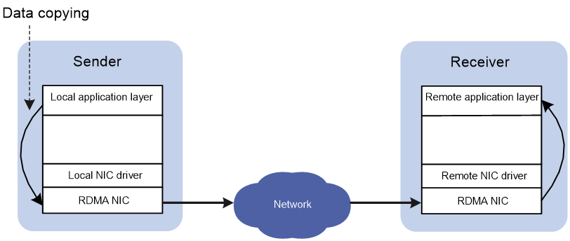
In traditional TCP/IP software and hardware architectures and applications, the network transmission and data processing delays are long, data are copied and interrupted multiple times, and TCP/IP protocol processing is complicated. Remote Direct Memory Access (RDMA) reduces the data processing delay on servers during the network transmission process. RDMA directly transmits the user application data to the storage space of the servers, and uses the network to fast transmit the data from the local system to the storage of the remote system. RDMA eliminates multiple data copying and text exchange operations during the transmission process, and reduces the CPU load.
Figure 1 Traditional TCP/IP data transmission process
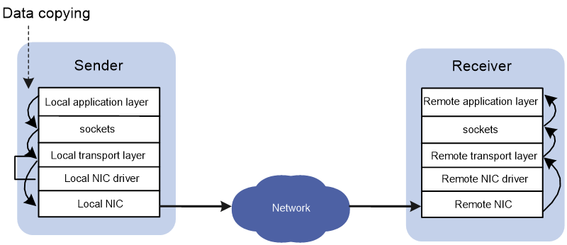
Figure 2 RDMA data transmission process
However, the InfiniBand network architecture dedicated to RDMA is closed, and must use IB switches and IB NICs. The InfiniBand network architecture cannot be compatible with the current network, and needs high costs. The RDMA over Converged Ethernet (RoCE) technology was introduced to effectively resolve these issues. RoCE supports carrying IB over Ethernet to implement RDMA over Ethernet.
RoCE has the following versions:
· RoCEv1—Carries RDMA over Ethernet. RoCEv1 can be deployed only on Layer 2 networks.
· RoCEv2—Carries RDMA over UDP/IP protocols. RoCEv2 can be deployed on Layer 3 networks.
Currently, all RDMA applications use the RoCEv2 protocol. However, because RDMA is initially designed based on a lossless InfiniBand network, RoCEv2 does not provide a perfect packet loss protection mechanism. The loss of any packet will cause a large number of retransmissions, and will seriously affect data transmission performance. At the same time, the applications related to HPC and distributed storage use the N:1 incast traffic model. Therefore, these applications easily cause transient congestion or even packet loss in the queue buffers of Ethernet switches. As a result, the latency will increase and the throughput will decrease for applications, and the distributed application performance will decrease. To support RoCEv2 and related applications on Ethernet switches, you must first deploy a lossless network on Ethernet switches.
Building a lossless Ethernet network to support RoCE
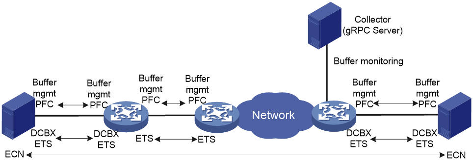
On an RoCE network, you must build a lossless Ethernet network to ensure zero packet loss. Lossless Ethernet must support the following key features:
· Data buffer management and monitoring—Adjusts the buffer space that each interface or queue can use according to traffic characteristics, and reports buffer usage conditions at the CLI or through gRPC.
Adjust the data buffer size under the guidance of professionals. As a best practice, configure data buffer monitoring.
· (Required.) PFC—Priority-based Flow Control. PFC provides per-hop priority-based flow control for multiple types of traffic separately.
· (Required.) ECN—Explicit Congestion Notification. When the device is congested, ECN marks the ECN field in the IP header of a packet. The receiver sends congestion notification packets (CNPs) to notify the sender to slow down the sending speed. ECN implements end-to-end congestion management and reduces the spread and deterioration of congestion.
· (Recommended.) DCBX—Data Center Bridging Capability Exchange Protocol. DCBX uses LLDP to autonegotiate DCB capabilities, including PFC and ETS capabilities. Typically, DCBX is used on the interface connecting the switch to the server, and negotiates capabilities with the server NIC.
· (Optional.) ETS—Enhanced Transmission Selection. ETS classifies traffic by service type, provides minimum guaranteed bandwidth for different traffic types, and improves the link utilization. ETS must be configured hop by hop.
Figure 3 Key features for building a lossless Ethernet
On an RoCE network, PFC must be used together with ECN to guarantee both zero packet loss and bandwidth. Table 1 compares PFC and ECN.
|
Item |
PFC |
ECN |
|
Network location |
Layer 2 |
Network layer and transport layer |
|
Effective scope |
Point-to-point |
End-to-end |
|
Need for network-wide support |
Yes |
No |
|
Controlled objects |
Previous node on the network (if the server NIC supports PFC, PFC also takes effect on the NIC) |
Sender host |
|
Packet buffer location |
Intermediate nodes and sender |
Sender |
|
Affected traffic |
All traffic in one of the eight queues on the device |
Congested connection |
|
Response speed |
Fast |
Slow |
This document describes the key technologies for building a lossless network, including data buffers, PFC, and ECN. For how to configure these technologies and other lossless network-related technologies, see the configuration guides and command references for your devices.
Data buffers
Data buffers temporarily store packets to avoid packet loss.
The following data buffers are available:
· Ingress buffer—Stores incoming packets.
· Egress buffer—Stores outgoing packets when network congestion occurs.
· Headroom buffer—Stores in-transit packets after PFC takes effect. The in-transit packets refer to packets transmitted between the time when the receiver sends PFC pause frames and the time when the sender receives PFC pause frames and actually stops sending packets.
Figure 4 shows the structure of ingress and egress buffers.
Figure 4 Data buffer structure

By default, all queues have an equal share of the shared area and fixed area. You can change the shared-area or fixed-area size for a queue. The unconfigured queues use the default setting.
PFC
About PFC
PFC is required for building a lossless Ethernet network. PFC provides per-hop priority-based flow control. When the device is forwarding packets, the device assigns packets to queues for scheduling and forwarding through looking up packet priorities in priority mapping tables. When the sending rate of packets carrying an 802.1p priority exceeds the receiving rate and the data buffer space on the receiver is insufficient, the receiver sends PFC pause frames to the sender. When the sender receives the PFC pause frames, the sender stops sending packets with the specified 802.1p priority until the sender receives PFC XON frames or the aging timer expires. When PFC is configured, the congestion of packets of a specific type does not affect the normal forwarding of the other types of packets, and different types of packets on a link are forwarded independently.
Mechanism
PFC pause frame generation mechanism
Figure 5 How PFC pause frames are generated
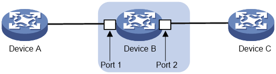
As shown in Figure 5, PFC pause frames are generated in the following process when Port 2 of Device B is congested:
1. When Port 1 of Device B receives packets from Device A, the memory management unit (MMU) of Device B allocates cell resources to the packets. If PFC is enabled on Device B, Device B counts the cell resources occupied by packets with each 802.1p priority.
|
|
NOTE: Cell resources are used to store packets. An interface allocates cell resources to packets based on packet sizes. Suppose a cell resource provides 208 bytes. An interface allocates one cell resource to a 128-byte packet and two cell resources to a 300-byte packet. |
2. When the cell resources used by packets carrying a certain 802.1p priority exceed the set threshold on Port 1 of Device B, Port 1 of Device B sends PFC pause frames for the 802.1p priority to Device A.
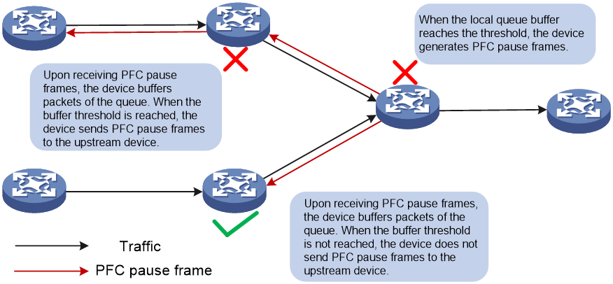
3. When Device A receives the PFC pause frames for the 802.1p priority, Device A stops sending out packets carrying the 802.1p priority and buffers these packets. If the buffer threshold for the 802.1p priority is reached, Device A sends PFC pause frames for the 802.1p priority to its upstream device, as shown in Figure 6.
Figure 6 PFC pause frame processing between multiple devices
Packet priority-to-queue mappings
When a device forwards packets, packets with different priority values are assigned to different queues for scheduling and forwarding. The packet priority-to-queue mappings depend on the priority mapping method configured. The device supports the following priority mapping methods:
· Configuring priority trust mode—In this method, you can configure an interface to trust the specified type of priority carried in packets. Then, the device looks up the trusted priority type in incoming packets in the priority maps and modifies the priority values in packets based on the priority maps. Packets are scheduled within the device based on the priorities. Available priority trust modes include:
¡ dot1p—Trusts the 802.1p priority carried in packets and uses the 802.1p priority for priority mapping.
¡ dscp—Trusts the DSCP priority carried in IP packets and uses the DSCP priority for priority mapping.
· Changing port priority—If no priority trust mode is configured for an incoming interface, the port priority of the incoming interface is used for priority mapping. By changing the port priority of an interface, you can change the priority of incoming packets on the interface. Then, packets received on different incoming interfaces can be assigned to the corresponding queues and scheduled differentiatedly.
When configuring PFC on an interface, you must configure the interface to trust the 802.1p or DSCP priority carried in packets. When the interface receives Ethernet packets, the interface marks local precedence values for packets according to the priority trust mode and the 802.1Q tagging status of packets. Then, the packets are scheduled based on their local precedence values. Figure 7 shows the detailed process.
|
|
NOTE: This document describes only the packet priority to local precedence mappings when the interface trusts the 802.1p or DSCP priority carried in packets. For information about the port priority configuration and the drop precedence (used as a reference for dropping packets), see the configuration guide for your device. |
Figure 7 Packet priority to queue mappings

PFC restrictions and guidelines
For PFC to work properly on an interface, perform the following tasks:
· Configure the interface to trust the 802.1p or DSCP priorities carried in packets by using the qos trust { dot1p | dscp } command.
· Make sure the 802.1p-to-local priority map and DSCP-to-802.1p priority map are the same on all interfaces along the transmission path.
You can configure PFC in both system view and Ethernet interface view. If you configure PFC in system view and Ethernet interface view multiple times, the most recent configuration takes effect.
For IRF and other protocols to operate correctly, as a best practice, do not enable PFC for 802.1p priority 0, 6, or 7.
To perform PFC on an IRF fabric, configure PFC on the IRF physical interfaces that are bound to the IRF port. For information about IRF, see Virtual Technologies Configuration Guide.
To perform PFC in an overlay network, execute the qos trust tunnel-dot1p command. For information about the overlay network, see VXLAN Configuration Guide. For information about the qos trust tunnel-dot1p command, see ACL and QoS Command Reference.
To avoid packet loss, apply the same PFC configuration to all interfaces that the packets pass through.
Setting PFC thresholds
About PFC thresholds
By configuring the PFC buffer thresholds, you can avoid tail drop in the sending data buffer when the buffer space is insufficient for incoming packets.
Figure 8 PFC buffer thresholds
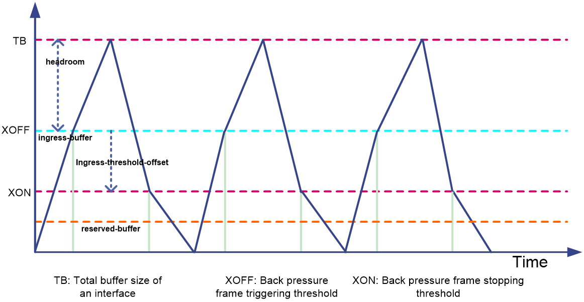
The device supports the following PFC thresholds:
· Headroom buffer threshold—Maximum number of cell resources that can be used by packets with a specific 802.1p priority value in a headroom storage space, as indicated by headroom in Figure 8. An interface drops received packets once this threshold is reached.
· Back pressure frame triggering threshold—Maximum number of cell resources that can be used by packets with a specific 802.1p priority value in a shared storage space, as indicated by XOFF in Figure 8. PFC is triggered to send PFC pause frames when this threshold is reached. The back pressure frame triggering threshold includes the following types:
¡ Dynamic back pressure frame triggering threshold—Maximum cell resources set in percentage.
¡ Static back pressure frame triggering threshold—Maximum cell resources set in an absolute value.
The XoffThres and IsDynamic fields in the display buffer usage interface verbose command output represent the back pressure frame triggering threshold and its type.
· Offset between the back pressure frame stopping threshold and triggering threshold—As indicated by ingress-threshold-offset in Figure 8. When the number of cell resources used by packets with a specific 802.1p priority value decreases by this offset after PFC is triggered, PFC will stop sending PFC pause frames.
· PFC reserved threshold—As indicated by reserved-buffer in Figure 8. Number of cell resources reserved for packets with a specific 802.1p priority value in a guaranteed storage space.
· Maximum number of cell resources in a headroom storage space—Number of cell resources allocated to the headroom storage space in a storage pool (only pool 0 is supported in the current software version).
PFC threshold restrictions and guidelines
After PFC is enabled for 802.1p priorities, the PFC thresholds use the default values, which are adequate in typical network environments. As a best practice, change the PFC thresholds only when necessary. If the network environment or traffic is complicated, consult the professionals to adjust the PFC thresholds.
Headroom buffer threshold
To set an exact headroom buffer threshold, calculate the threshold as follows:
1. Calculate the size of in-transit traffic (traffic transmitted between the time the receiver sends PFC pause frames and the time the sender receives PFC pause frames and actually stops sending packets). The formula is in-transit traffic (bytes) = MTUR + MTUs + Response + 2*link_delay, where the parameters are defined as follows:
¡ MTUR—Length of a large packet if the chip needs to send a large packet between the time the back pressure frame trigger threshold is triggered and the time the device sends PFC pause frames. Because the large packet might come from any queue, the packet length must be the maximum length of frames allowed to pass through, 9216 bytes.
¡ MTUs—Length of the packet that the upstream device sends immediately before stopping sending packets. Because only packets with the specified 802.1p priority affect the threshold on the receiver, the MTUs is the length of a packet with the 802.1p priority specified by PFC.
¡ Response—Length of data generated within the response time between the time the upstream device receives PFC pause frames and the time the device stops sending packets. The value is fixed at 3840 bytes.
¡ 2*link_delay—Length of the forward and backward buffered packets on the link, as shown in the following table:
|
Interface speed |
Buffered packets (bytes) in each 100 meter of cable |
|
10 Gbps |
1300 |
|
25 Gbps |
3250 |
|
40 Gbps |
5200 |
|
100 Gbps |
13000 |
In conclusion, in-transit traffic (bytes) = 9216 + MTUs + 3840 + N*packets buffered (bytes) in each 100 meter of cable, where N is the cable length (in 100 meters).
2. Calculate the number of cell resources needed by the in-transit traffic. At the same time, you need to consider the influence of packet length on cell resource allocation. In extreme conditions where each packet is of 64 bytes, most cell resources are occupied.
¡ On the S6805 switch series, S6825 switch series, S6850 switch series, and S9850 switch series, each cell resource provides 256 bytes.
¡ On the S9820-64H switches, each cell resource provides 208 bytes.
¡ On the S9820-8C switches, each cell resource provides 254 bytes.
¡ On the S9825 switch series, each cell resource provides 254 bytes.
¡ On the S9855 switch series, each cell resource provides 318 bytes.
¡ On the S12500R switch router series, each cell resource provides 4096 bytes.
Maximum number of available cell resources in the headroom
The headroom resources are preempted by all ports and all queues on the device. Consider the headroom space needed by each port and the number of ports, and then determine a small value that can meet the requirements.
Back pressure frame triggering threshold
When determining the back pressure frame triggering threshold, analyze the network traffic model, and make sure the sum of back pressure frame triggering thresholds on all incoming interfaces does not exceed the tail drop threshold of the outgoing interface. The tail drop threshold of the outgoing interface is configured by using the buffer egress cell queue shared ratio command, 20% by default. In a lossless Ethernet network, the value can be set to 100%. Calculate the proportion of traffic on each incoming interface to the total buffer. Then, obtain the dynamic back pressure frame triggering threshold (in percentage) based on Table 2. At last, adjust the threshold in actual traffic conditions to obtain the optimal value, and configure the value on the incoming interface.
Table 2 Dynamic back pressure frame triggering thresholds
|
Percentage (dynamic back pressure frame triggering threshold) |
Alpha value (ratio of cells in a queue to available cells, configured by the chip register) |
Proportion to total buffer |
|
0 |
1/128 |
0.77 |
|
1 |
1/64 |
1.53 |
|
2 to 3 |
1/32 |
3.03 |
|
4 to 5 |
1/16 |
5.88 |
|
6 to 11 |
1/8 |
11.11 |
|
12 to 20 |
1/4 |
20.00 |
|
21 to 33 |
1/2 |
33.33 |
|
34 to 50 |
1 |
50.00 |
|
51 to 66 |
2 |
66.66 |
|
67 to 80 |
4 |
80.00 |
|
81 to 100 |
8 |
88.88 |
Additionally, when PFC is used together with ECN, for ECN to take effect first, make sure the back pressure frame triggering threshold (the number of cell resources) is greater than the high-limit value configured in the queue queue-id [ drop-level drop-level ] low-limit low-limit high-limit high-limit [ discard-probability discard-prob ] command.
Calculate the number of cell resources for the back pressure frame triggering threshold by using the formula: Used=Total*Alpha/(1+N*Alpha), where the parameters are defined as follows:
· Used—Buffer size used by a single flow when multiple flows are congested.
· Total—Total buffer of the device. The value for this argument varies by device series:
¡ For the S6805, S6825, S6850, and S9850 switch series, the value is 128K cell resources.
¡ For the S9820-64H switches, the value is 204K cell resources.
¡ For the S9820-8C switches, the value is 258K cell resources.
¡ For the S9825 switch series, the value is 451K cell resources.
¡ For the S9855 switch series, the value is 264K cell resources.
¡ For the S12500R switch router series, the value is 1000K cell resources.
The S9825 switch series support two Ingress Traffic Managers (ITMs). Ports that use the same ITM share ingress buffer resources. On the S9825-64D switches, ports 1 to 32 share one ITM and ports 33 to 64 share another ITM.
· Alpha—Ratio of cells in a queue to available cells.
· N—Number of congested flows that can be processed by the network.
Offset between the back pressure frame stopping threshold and triggering threshold
Configure the offset as a value slightly greater than the maximum length of a packet with the specified priority. Too large an offset will slow down the back pressure frame stopping speed and affects the traffic sending speed.
PFC reserved threshold
As a best practice, configure the PFC reserved threshold as a value slightly greater than the maximum length of a packet with the specified priority. You can calculate the PFC reserved threshold value as follows: (maximum length of a packet carrying the specified priority + packet header length (64 bytes) + bytes of one cell resource)/(bytes of one cell resource).
Configuring PFC deadlock detection
About PFC deadlock detection
Typically, when an interface is congested and the PFC back pressure frame triggering threshold is reached, the device sends PFC pause frames to the upstream device. Upon receiving the PFC pause frames, the upstream device stops sending packets. If the back pressure frame triggering threshold is reached on the upstream device, the upstream device sends PFC pause frames to its upstream device, and so on. This process is repeated until the server that sends packets receives the PFC pause frames. Then, the server stops sending packets within the PFC pause time specified in the PFC pause frames. This process reduces the packet sending rate at the source end and eliminates packet loss caused by congestion on network nodes.
In some special conditions, for example, when a link or device fails, a temporary loop might appear during the route convergence period. In this case, devices repeatedly send and receive PFC pause frames, and packets cannot be forwarded. As a result, the cell resources in the interface buffer cannot be released, and the device enters the PFC deadlock state.
As shown in Figure 9, the original path for traffic from Server 1 to Server 2 is Server 1—>Device C—>Device A—>Device D—>Server 2. Suppose the link between Device D and Server 2 fails. During the route convergence period, a forwarding path Server 1—>Device C—>Device A—>Device D—>Device B—>Device C—>Server 2 appears. Therefore, a loop Device C—>Device A—>Device D—>Device B—>Device C exists. If the interface connecting Device C to Server 2 is congested, Device C sends PFC pause frames to the upstream device. Then, these PFC pause frames will be forwarded in the loop mentioned above, and each device along the loop stops sending packets and waits for the peer to release cell resources. In this case, the devices along the loop enter the PFC deadlock state.
Figure 9 How a PFC deadlock is generated
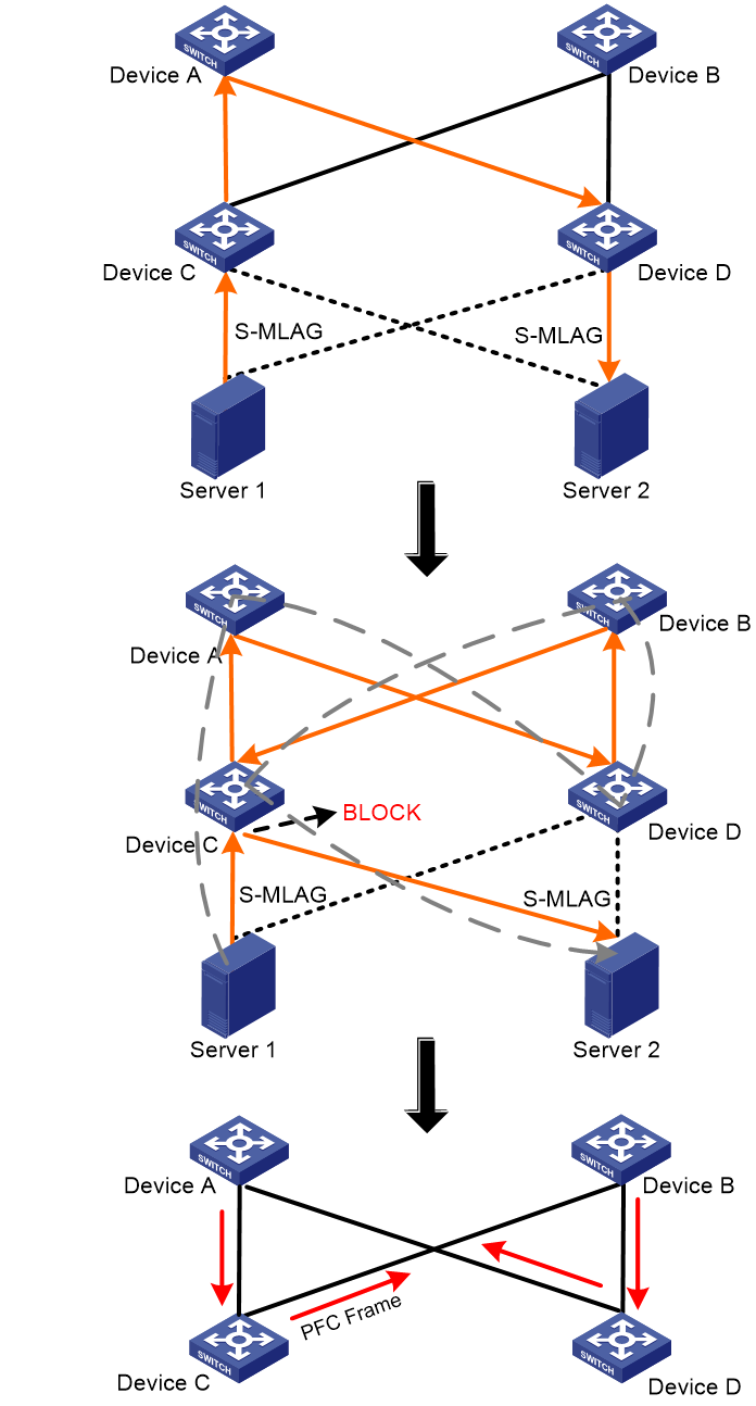
To remove the PFC deadlock on these devices, disable PFC or ignore the received PFC pause frames (which are used to notify the devices to stop sending packets) to resume packet sending on the devices, and forward or drop packets in the buffer. The PFC deadlock detection interval can be accurate to the millisecond level, and can reduce the influence of PFC deadlocks efficiently.
Restrictions and guidelines
The specified CoS value must be within the 802.1p priority list specified by using the priority-flow-control no-drop dot1p command. To view the 802.1p priority for each CoS value, execute the display qos map-table dot1p-lp command.
PFC deadlock detection interval
The PFC deadlock detection interval for a CoS value is the product of the interval argument configured by using the priority-flow-control deadlock cos interval command and the precision configured by using the priority-flow-control deadlock precision command. For example, if you execute the priority-flow-control deadlock cos 5 interval 10 command to set the interval argument to 10 for CoS priority 5 and execute the priority-flow-control deadlock precision command to set the precision to high (which represents 10 milliseconds) for CoS priority 5, the PFC deadlock detection interval for CoS priority 5 is 10*10 =100 milliseconds.
Delay timer for PFC deadlock detection automatic recovery
When PFC deadlock is detected on a device, the device ignores received PFC XOFF frames and disables PFC deadlock detection during the delay timer for PFC deadlock detection automatic recovery. Then, packets can be forwarded properly.
The delay timer is 100 milliseconds + delay-interval * 100 milliseconds. For example, if you execute the priority-flow-control deadlock auto-recover cos 5 delay 10 command to set the delay-time argument to 10 for CoS priority 5, the delay timer for CoS priority 5 is 100 milliseconds + 10 * 100 milliseconds =1100 milliseconds.
PFC deadlock recovery mode
After the PFC deadlock is removed on a device, PFC deadlock detection must be recovered, and PFC is recovered at the same time. PFC deadlock detection can be recovered in automatic mode or manual mode.
Typically, use the automatic recovery mode when no serious failures occur. When a packet loop cannot be removed and the device enters the PFC deadlock state frequently, manually recover PFC deadlock detection on an interface as follows:
1. Set the PFC deadlock detection recovery mode to manual on the interface.
2. Troubleshoot the device. After the failures are solved, execute the priority-flow-control deadlock recover command to recover the PFC deadlock detection and PFC features on the interface.
After the upper threshold for PFC deadlock times during the specified period is configured, if the PFC deadlock times within the specified period exceed the upper threshold on an interface, the device disables PFC for the corresponding priority on the interface. To recover the PFC feature on the interface in this case, troubleshoot the device and execute the undo priority-flow-control deadlock threshold command after the failures are solved.
Early warning thresholds for PFC packets
You can configure the early warning threshold for incoming or outgoing PFC packets of an interface as needed. The early warning threshold notifies a situation where the PFC packet transmission rate is still within a normal range but needs attention.
When the rate of PFC packets that an interface sends or receives reaches the early warning threshold, the system generates traps and logs to notify the user. According to the traps and logs, the user can discover some exceptions on the network, for example:
· The NIC of the peer device fails and continuously sends PFC packets at a high speed. In this case, you can set the early warning threshold for incoming PFC packets.
· The device fails and continuously sends PFC pause frames. In this case, you can set the early warning threshold for outgoing PFC packets.
To monitor bidirectional PFC packets, you can set the early warning thresholds for incoming packets and outgoing packets separately.
ECN
About ECN
ECN is required for building a lossless Ethernet network. ECN defines a traffic control and end-to-end congestion notification mechanism based on the IP layer and transport layer. ECN uses the DS field in the IP header to mark the congestion status along the packet transmission path. An ECN-capable endpoint can determine whether congestion occurs on the transmission path according to the packet contents. Then, the endpoint adjusts the packet sending speed to avoid deteriorating congestion.
Mechanism
ECN defines the last two bits (ECN field) in the DS field of the IP header as follows:
· Bit 6 indicates whether the sending endpoint device supports ECN, and is called the ECN-Capable Transport (ECT) bit.
· Bit 7 indicates whether the packet has experienced congestion along the transmission path, and is called the Congestion Experienced (CE) bit.
|
|
NOTE: In actual applications, the following packets are considered as packets that an ECN-capable endpoint sends: · Packets with ECT set to 1 and CE set to 0. · Packets with ECT set to 0 and CE set to 1. |
Figure 10 DS field location

Figure 11 ECN field location
![]()
After you enable ECN on a device, the device processes incoming packets as follows:
· When the device assigns packets to a queue in the outbound direction, if the average queue size is below the lower threshold (ECN threshold), the device does not process these packets, and directly forwards them out of the outgoing interface.
· When the device assigns packets to a queue in the outbound direction, if the average queue size is between the lower threshold and the upper threshold, the device performs the following operations:
¡ If the ECN field is 00, which shows that the packets are sent out of an ECN-incapable terminal, the device calculates whether to drop a packet according to the drop probability.
¡ If the ECN field is 01 or 10, which shows that the packets are sent out of an ECN-capable terminal, the device performs the following operations:
- Sets both the ECT bit and the CE bit to 1 for some of these packets according to the drop probability and forwards these packets.
- Forwards all incoming packets.
¡ If the ECN field is 11 in a packet, the device forwards the packet without modifying the ECN field. The combination of ECT bit 1 and CE bit 1 indicates that the packet has experienced congestion along the transmission path.
· When the device assigns packets to a queue in the outbound direction, if the average queue size exceeds the upper threshold, the device performs the following operations:
¡ If the ECN field is 00, which shows that the packets are sent out of an ECN-incapable terminal, the device drops the packets.
¡ If the ECN field is 01 or 10, which shows that the packets are sent out of an ECN-capable terminal, the device performs the following operations:
- Sets both the ECT bit and the CE bit to 1 and forwards these packets.
- Forwards all incoming packets.
- If the ECN field is 11 in a packet, the device forwards the packet without modifying the ECN field. The combination of ECT bit 1 and CE bit 1 indicates that the packet has experienced congestion along the transmission path.
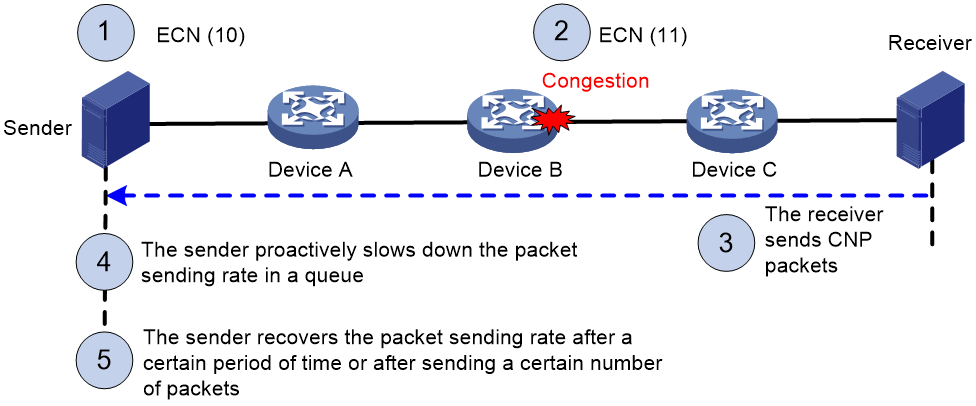
ECN works in the following flow:
1. The sender sets the ECN field to 10, and notifies the devices along the transmission and the receiver that the sender supports ECN.
2. When congestion occurs on an intermediate device, the congested device sets the ECN field to 11 for congested packets, and normally forwards the packets.
3. When the receiver receives packets with the ECN field set to 11, the transport layer sends congestion notification packets (CNPs) to the sender.
4. When receiving the CNPs, the sender slows down the sending rate of packets with the specified priority.
5. After a configurable period of time or the specified number of packets are sent, the sender resumes the original sending rate.
Figure 12 ECN working mechanism
Guidelines for hardware compatibility with lossless network
As a best practice, use the following devices for lossless network deployment:
· S6805 switch series
· S6825 switch series
· S6850 switch series
· S9825 switch series
· S9850 switch series
· S9855 switch series
· S9820-64H/S9820-8C switches
· Specific devices and service modules in the S12500R switch router series:
¡ Expandable fixed-port S12500R switch routers, such as S12500R-48Y8C and S12500R-48C6D.
¡ KCR service modules, such as LSXM1CGQ72KCR1 and LSXM1CDMS36KCR1.
¡ KBR service modules, such as LSXM1CDQ36KBR1, LSXM2CGQ48KBR1, and LSXM1CDQ24KBR1.
¡ KB service modules, such as LSXM1CGQ48KB1.
As a best practice, use expandable fixed-port S12500R switch routers or KCR service modules.
If KBR service modules or KB service modules are used, you must configure SP queuing on output interfaces rather than WFQ or WRR queuing.
Guidelines for tuning lossless network parameters
About tuning lossless network parameters
Typically, set up the network according to the best practices and configuration guides, and use the recommended PFC and ECN settings. The recommended settings are optimal for general network environments. Do not tune the parameters unless otherwise required.
In some cases, because the devices and servers in the network configuration are special, you must tune the parameters. For more information, see “Tuning the parameters.”
Recommended settings
Recommended PFC settings
After you enable PFC for an 802.1p priority on an S6805 & S6825 & S6850 & S9850, S9820-64H, S9820-8C, S9825 & S9855, or S12500R device, the device will set default values for PFC thresholds. For more information, see Table 3, Table 4, Table 5, Table 6, and Table 7. Table 6 also displays the recommended PFC thresholds on the S9825 & S9855 switches.
The default settings are optimal for general network environments. Do not tune the parameters unless otherwise required.
Table 3 Default PFC thresholds on the S6805 & S6825 & S6850 & S9850 switches
|
PFC threshold (right) Interface type (below) |
Headroom buffer threshold (cell) |
Dynamic back pressure frame triggering threshold (%) |
Offset between the back pressure frame stopping threshold and triggering threshold (cell) |
PFC reserved threshold (cell) |
|
1GE/10GE |
100 |
5 |
12 |
17 |
|
25GE |
125 |
5 |
12 |
17 |
|
40GE |
200 |
5 |
12 |
17 |
|
50GE |
308 |
5 |
12 |
17 |
|
100GE |
491 |
5 |
12 |
17 |
Table 4 Default PFC thresholds on the S9820-64H switches
|
PFC threshold (right) Interface type (below) |
Headroom buffer threshold (cell) |
Dynamic back pressure frame triggering threshold (%) |
Offset between the back pressure frame stopping threshold and triggering threshold (cell) |
PFC reserved threshold (cell) |
|
25GE |
125 |
5 |
12 |
20 |
|
100GE |
491 |
5 |
12 |
20 |
Table 5 Default PFC thresholds on the S9820-8C switches
|
PFC threshold (right) Interface type (below) |
Headroom buffer threshold (cell) |
Dynamic back pressure frame triggering threshold (%) |
Offset between the back pressure frame stopping threshold and triggering threshold (cell) |
PFC reserved threshold (cell) |
|
100GE |
491 |
5 |
12 |
20 |
|
200GE |
705 |
5 |
12 |
20 |
|
400GE |
1000 |
5 |
12 |
20 |
Table 6 Default PFC thresholds and recommended PFC thresholds on the S9825 & S9855 switches
|
PFC threshold (right) Interface type (below) |
Headroom buffer threshold (cell) |
Dynamic back pressure frame triggering threshold (%) |
Offset between the back pressure frame stopping threshold and triggering threshold (cell) |
PFC reserved threshold (cell) |
|
100GE |
491 |
The default value is 3 and the recommended value is 5. |
The default value is 48 and the recommended value is 12. |
The default value is 0 and the recommended value is 16. |
|
200GE |
750 |
The default value is 3 and the recommended value is 5. |
The default value is 48 and the recommended value is 12. |
The default value is 0 and the recommended value is 16. |
|
400GE |
1000 |
The default value is 3 and the recommended value is 5. |
The default value is 48 and the recommended value is 12. |
The default value is 0 and the recommended value is 16. |
Table 7 Default PFC thresholds on the S12500R switch routers
|
PFC threshold (right) Interface type (below) |
Headroom buffer threshold (cell) |
Dynamic back pressure frame triggering threshold (%) |
Offset between the back pressure frame stopping threshold and triggering threshold (cell) |
PFC reserved threshold (cell) |
|
25GE |
50000 |
2 |
1024 |
256 |
|
100GE |
100000 |
2 |
1024 |
256 |
|
200GE |
200000 |
3 |
1024 |
256 |
|
400GE |
300000 |
6 |
1024 |
256 |
Recommended ECN settings
For the ECN feature, Table 8 shows the recommended settings for the RoCE queues. You can configure lower threshold and upper threshold for the average queue length to be greater than the default settings.
|
|
NOTE: In the following table, the measurement unit of the Lower limit for the average queue length and Upper limit for the average queue length fields is byte for S12500R devices and is cell for other devices. |
Table 8 Recommended ECN thresholds
|
PFC threshold (right) Interface type (below) |
Lower limit for the average queue length |
Upper limit for the average queue length |
Drop probability |
Exponent for average queue length calculation |
|
1GE/10GE |
400 |
1625 |
20 |
0 |
|
25GE |
· S12500R devices: 1000000 · Other devices: 400 |
· S12500R devices: 8000000 · Other devices: 1625 |
20 |
0 |
|
50GE |
600 |
1500 |
20 |
0 |
|
100GE |
· S12500R devices: 1000000 · Other devices: 1000 |
· S12500R devices: 8000000 · Other devices: 2000 |
20 |
0 |
|
200GE |
· S12500R devices: 1000000 · Other devices: 1500 |
· S12500R devices: 8000000 · Other devices: 3000 |
20 |
0 |
|
400GE |
· S12500R devices: 1000000 · Other devices: 2100 |
· S12500R devices: 8000000 · Other devices: 5000 |
20 |
0 |
NIC settings for reference
Make sure the server NICs support PFC and ECN and have PFC and ECN enabled. For more information, see the documents for the servers. Identify whether packets in the RoCE queues of the servers carry the ECN flags.
This document uses the Mellanox ConnectX-6 Lx NICs as an example.
NOTE: The settings of a NIC do not take effect after the server or the NIC is rebooted, because the NIC settings are not written to the configuration file. You must configure the NIC settings again after the server or NIC is rebooted.
NIC model and version
|
Item |
Information |
|
NIC model |
Ethernet controller: Mellanox Technologies MT2894 Family [ConnectX-6 Lx] |
|
NIC driver version |
MLNX_OFED_LINUX-5.4-3.2.7.2.3-rhel8.4-x86_64 |
|
NIC firmware version |
driver: mlx5_core version: 5.4-3.2.7.2.3 firmware-version: 26.31.2006 (MT_0000000531) |
Prerequisites
1. Execute the mst start command to enable the Mellanox Software Tools (MST) service.
2. Execute the mst status command to view the Mellanox device status.
3. (Optional.) Execute the show_gids command to view the name, GID, and IP address of the NIC.
Configuring the NIC interface to trust the DSCP priority values in packets
1. Execute the mlnx_qos -i ifname --trust dscp command to configure the interface to trust the DSCP priority values in packets.
The ifname argument represents the NIC interface name.
2. Additionally, make sure the DSCP priority configured for packets on the NIC corresponds to the DSCP priority of RoCE packets on the device. That is, the 802.1p priority for which PFC and ECN are enabled on the device must be mapped to the DSCP priority value in the packets sent out of the NIC.
Configuring the DSCP priority of CNP packets
1. Use the ethtool -i ifname bus-info command to view the bus-info of an interface.
For example, to view the bus-info of ens1f0, execute the ethtool -i ens1f0 bus-info command. In the command output, you can see that the bus-info of ens1f0 is 0000:86:00.0.
2. Enter the DSCP priority setting path: cd /sys/kernel/debug/mlx5/0000:86:00.0/cc_params
3. Execute the echo priority_value > np_cnp_dscp command to set the DSCP priority of CNP packets.
For example, to set DSCP priority 48 for CNP packets, execute the echo 48 > np_cnp_dscp command.
4. Execute the cat np_cnp_dscp command to identify whether the DSCP priority is successfully set for CNP packets.
Enabling PFC for the RoCE queues
1. Execute the mlnx_qos -i ifname ––pfc 0,1,2,3,4,5,6,7 command to enable PFC for the RoCE queues.
The ifname parameter represents the NIC interface name. If you specify 0 in the position of an 802.1p priority in the 0,1,2,3,4,5,6,7 parameter, PFC is disabled for the corresponding 802.1p priority. If you specify 1, PFC is enabled. For example, to enable PFC for packets with 802.1p priority 5 on ens1f0, execute the mlnx_qos -i ens1f0 –-pfc 0,0,0,0,0,1,0,0 command.
2. Execute the mlnx_qos -i ifname command to view the PFC enabling state on an interface.
The value of 1 means that PFC is enabled for packets with the specified priority.
Enabling ECN for the RoCE queues
1. Execute the following commands to enable ECN for packets with the specified priority:
¡ echo 1 > /sys/class/net/ifname/ecn/roce_np/enable/priority_value
¡ echo 1 > /sys/class/net/ifname/ecn/roce_rp/enable/priority_value
For example, to enable ECN for packets with priority 5 on ens1f0, execute the following command:
¡ echo 1 > /sys/class/net/ens1f0/ecn/roce_np/enable/5
¡ echo 1 > /sys/class/net/ens1f0/ecn/roce_rp/enable/5
2. Execute the following command to identify whether ECN is successfully enabled.
The value of 1 means ECN is successfully enabled, and the value of 0 means ECN is not enabled.
¡ cat /sys/class/net/ifname/ecn/roce_np/enable/priority_value
¡ cat /sys/class/net/ifname/ecn/roce_rp/enable/priority_value
Tuning the parameters
Restrictions and guidelines
When tuning parameters, port traffic will be interrupted if the following commands related to PFC, QoS, and data buffer are executed:
· buffer apply
· buffer egress cell queue shared (executing this command does not cause packet loss, but executing the buffer apply command to apply this configuration will cause packet loss)
· qos wred apply
· qos wrr weight
· qos wrr group weight
· qos wfq byte-count
· qos wfq queue-id group { 1 | 2 } byte-count
· priority-flow-control no-drop dot1p
· priority-flow-control dot1p headroom
· priority-flow-control dot1p ingress-buffer dynamic
· priority-flow-control dot1p ingress-buffer static
· priority-flow-control dot1p ingress-threshold-offset
· priority-flow-control dot1p reserved-buffer
Identifying whether packets are dropped
Identifying whether packets are dropped on an interface
# View the dropped packets on interface HundredGigE 1/0/25.
<Sysname> display packet-drop interface hundredgige 1/0/25
HundredGigE1/0/25:
Packets dropped due to Fast Filter Processor (FFP): 0
Packets dropped due to Egress Filter Processor (EFP): : 0
Packets dropped due to STP non-forwarding state: 0
Packets dropped due to insufficient data buffer. Input dropped: 0 Output dropped: 0
Packets of ECN marked: 0
Packets of WRED droped: 0
Troubleshooting packet drops caused by insufficient data buffer
1. If input dropped packets exist, you can increase the headroom buffer threshold. As a best practice, increase the threshold by the current value each time until no input dropped packet exist. For example:
# Set the headroom buffer threshold to 982.
<sysname> system-view
[Sysname] interface hundredgige 1/0/25
[Sysname-HundredGigE1/0/25] priority-flow-control dot1p 5 headroom 982
If packets are still dropped when you have increased the threshold to the maximum value, identify whether the server NIC supports PFC and has PFC enabled.
2. If output dropped packets exist, identify whether the maximum shared-area ratio is configured as 100% and whether the buffer apply command is applied. For example:
# Configure queue 5 to use up to 100% shared-area space of cell resources in the egress buffer and apply the configuration.
<sysname> system-view
[Sysname] buffer egress cell queue 5 shared ratio 100
[Sysname] buffer apply
If output dropped packets still exist after the maximum shared-area ratio is set to 100% for the queue in the egress buffer, possible causes are network or configuration issues. Troubleshoot the network and configuration issues, or contact Technical Support.
Troubleshooting WRED dropped packets
1. If WRED dropped packets exist, identify whether ECN is enabled for the RoCE queues.
<Sysname> display qos wred table
Table name: 1
Table type: Queue based WRED
QID gmin gmax gprob ymin ymax yprob rmin rmax rprob exponent ECN
----------------------------------------------------------------------------
0 100 1000 10 100 1000 10 100 1000 10 9 N
1 100 1000 10 100 1000 10 100 1000 10 9 N
2 100 1000 10 100 1000 10 100 1000 10 9 N
3 100 1000 10 100 1000 10 100 1000 10 9 N
4 100 1000 10 100 1000 10 100 1000 10 9 N
5 100 1000 10 100 1000 10 100 1000 10 9 N
6 100 1000 10 100 1000 10 100 1000 10 9 N
7 100 1000 10 100 1000 10 100 1000 10 9 N
2. If ECN is not enabled for an RoCE queue (N is displayed in the ECN column for the RoCE queue), you must enable ECN for that RoCE queue.
<Sysname> system-view
[Sysname] interface hundredgige 1/0/25
[Sysname-HundredGigE1/0/25] qos wred queue 5 ecn
3. If the number of WRED dropped packets keeps increasing after you enable ECN for the RoCE queue, identify whether the packets from the RoCE queue carry the ECN flag. If they do not carry the ECN flag, identify whether the server has PFC and ECN enabled.
4. If packet loss persists, contact Technical Support.
Identifying whether the latency meets the requirements
To meet the latency requirements, you can tune some ECN and PFC parameters to reduce the latency on the condition that packets are not lost. Tuning the latency will affect the throughout as follows when the network is congested:
· The less buffer is used, the lower the latency and the lower the throughput.
· The more buffer is used, the higher the latency and the higher the throughput.
Balance the relationship between latency and throughput according to the network requirements.
When the network is not congested, PFC and ECN do not take effect. After ECN and PFC are triggered, the packet forwarding rate is decreased. When tuning the parameters, try to trigger ECN and PFC on the condition that packets are not lost with as low buffer usage as possible. As a best practice, first tune ECN parameters.
Additionally, when you tune parameters, consider the server NIC capabilities, including the response mechanisms for PFC and ECN packets and the PFC and ECN-related capabilities. For example, some NICs support automatically decreasing the speed when the latency is high. In this case, suppose you want to tune parameters to increase the throughput. However, the tuned parameters increase the latency and cause the server to automatically decrease the speed and the throughput, causing unexpected results. As a best practice, before tuning parameters, first read related documents of the server, learn the support of server NICs for PFC and ECN, and identify whether the tuned parameters are appropriate during the tuning process.
Tuning ECN parameters
You can tune the following parameters for queues in the WRED table to control the latency and throughput:
· Low-limit (lower limit for the average queue length) and high-limit (upper limit for the average queue length)—By tuning down the low-limit and high-limit values, you can trigger the ECN flag faster to decrease the latency. However, this operation might decrease the throughput.
· Weighting-constant (exponent for average queue length calculation)—Specify the method of calculating the average queue length. The value of 0 indicates the average queue length is the real-time queue length and more sensitive to ECN flags. The greater the exponent for average queue length calculation, the less sensitive the average queue length is to real-time queue length changes. As a best practice, use the recommended value. Try to tune this parameter only when other tuning attempts do not take effect.
· Discard-probability (drop probability)—After ECN is enabled, this parameter represents the ECN flag probability. A greater value means more packets between the lower limit and upper limit are marked with ECN flags. As a best practice, use the recommended value. Try to tune this parameter only when other tuning attempts do not take effect. As a best practice, tune the drop probability by 20% each time.
Example:
# Configure WRED parameters for queue 5: set the lower limit and upper limit for the average queue length to 800 and 1800, respectively.
<Sysname> system-view
[Sysname] qos wred queue table queue-table1
[Sysname-wred-table-queue-table1] queue 5 drop-level 0 low-limit 800 high-limit 1800
[Sysname-wred-table-queue-table1] queue 5 drop-level 1 low-limit 800 high-limit 1800
[Sysname-wred-table-queue-table1] queue 5 drop-level 2 low-limit 800 high-limit 1800
Tuning PFC parameters
|
|
CAUTION: Tuning the PFC thresholds when traffic is being received or sent might cause packet loss. |
PFC is a barrier behind ECN to ensure that packets are not lost. Typically, PFC is not triggered and does not seriously affect the latency. Additionally, lower PFC thresholds will decrease the throughput. As a best practice, do not tune PFC parameters unless required.
To further decrease the latency, try to tune the ingress-buffer parameter (back pressure frame trigger threshold).
1. Decrease the ingress-buffer threshold.
As a best practice, tune the ingress-buffer threshold together with the high-limit parameter of WRED (tune down the value by 10% of the current value each time). However, you must make sure the ingress-buffer threshold is greater than the high-limit of WRED, so that ECN is preferentially triggered on the device.
# Set the dynamic back pressure frame triggering threshold to 4.
<sysname> system-view
[Sysname] interface hundredgige 1/0/25
[Sysname-HundredGigE1/0/25] priority-flow-control dot1p 5 ingress-buffer dynamic 4
2. After tuning this parameter value, execute the following command multiple times to view the PFC information of interfaces. Make sure as few PFC frames as possible are received and sent on the device (PFC is not triggered or occasionally triggered).
If you see that PFC packets are received and sent multiple times, the ingress-buffer threshold is too low. As a best practice, increase the threshold.
# Display the PFC information of interfaces.
<Sysname> display priority-flow-control interface
Conf -- Configured mode Ne -- Negotiated mode P -- Priority
Interface Conf Ne Dot1pList P Recv Sent Inpps Outpps
HGE1/0/25 Auto On 0,2-3,5-6 0 178 43 12 15
Lossless network configuration examples
Example: Configuring a data center RDMA network
Network configuration
As shown in Figure 13:
· The RDMA network uses the two-level spine-leaf architecture. The spine devices are S9820-8C switches, and the leaf devices are S6850-56HF devices.
· The leaf devices act as the gateways of the servers. A Layer 3 ECMP network is built between spine devices and leaf devices. The Layer 3 ECMP network forwards data at a high speed and also supports redundancy of forwarding paths.
· Simple Multichassis Link Aggregation (S-MLAG) is run between the member devices in the same leaf device group. Each server accesses the leaf devices through a dynamic aggregate interface with two member interfaces.
· The server NICs use bonding mode 4 (dynamic aggregation mode).
Configure the network, so that RDMA application packets can be lossless transmitted in queue 5.
|
|
NOTE: This example uses four spine devices and four leaf devices. In actual applications, you can deploy eight S9820-8C switches on the spine layer and 96 S6850-56HF switches on the leaf layer to build an RDMA network with the convergence ratio of 1.5:1. |
|
|
CAUTION: When the server NICs use bonding mode 4, dynamic aggregation must be configured on access switches. A server needs to support two uplink interfaces that both send ARP packets, so that the two access switches of the server can learn the ARP entries of the server. When any member interface in the aggregation group on a server goes down and then comes up, the server must send ARP packets to the access switches. Then, the switches can update the ARP entries and generate host routes. When the server NICs use bonding mode 1 (active/backup mode), the requirements are as follows: · The access switches can use dynamic or static aggregation. When an interface on a server becomes inactive and then becomes active, the server NIC must be able to send ARP packets to the access switches. Then, the switches can update the ARP entries and generate host routes. · When dynamic aggregation is configured on switches, you must execute the lacp edge-port command on the aggregate interfaces on the access switches to configure the interfaces as edge aggregate interfaces. · As a best practice, set the ARP entry aging timer to 30 seconds. In this case, when a server NIC interface becomes inactive but does not go down, the switches can fast update ARP entries and generate host routes to reduce the packet loss time. As a best practice to avoid increasing the CPU burden, do not configure too short an ARP entry aging time. |

|
Device |
Interface |
IP address |
Device |
Interface |
IP address |
|
NOTE: The interface numbering rules on Spine 2, Spine 3, and Spine 4 are the same as those on Spine1. The interface numbering rules on Leaf 1-2, Leaf 2-1, and Leaf 2-2 are the same as those on Leaf 1-1. Interface numbers are not all marked to make the network diagram simple. |
|||||
|
Leaf 1-1 |
HGE1/0/25 |
9.179.56.1/31 |
Spine 1 |
HGE1/1/1 |
9.179.56.0/31 |
|
HGE1/0/26 |
9.179.56.193/31 |
HGE1/1/2 |
9.179.56.2/31 |
||
|
HGE1/0/27 |
9.179.57.129/31 |
HGE1/1/3 |
9.179.56.4/31 |
||
|
HGE1/0/28 |
9.179.58.65/31 |
HGE1/1/4 |
9.179.56.6/31 |
||
|
Vlan-int2 |
9.179.64.1/26 |
Spine 2 |
HGE1/1/1 |
9.179.56.192/31 |
|
|
Leaf 1-2 |
HGE1/0/25 |
9.179.56.3/31 |
HGE1/1/2 |
9.179.56.194/31 |
|
|
HGE1/0/26 |
9.179.56.195/31 |
HGE1/1/3 |
9.179.56.196/31 |
||
|
HGE1/0/27 |
9.179.57.131/31 |
HGE1/1/4 |
9.179.56.198/31 |
||
|
HGE1/0/28 |
9.179.58.67/31 |
Spine 3 |
HGE1/1/1 |
9.179.57.128/31 |
|
|
Vlan-int2 |
9.179.64.1/26 |
HGE1/1/2 |
9.179.57.130/31 |
||
|
Leaf 1-1 |
HGE1/0/25 |
9.179.56.5/31 |
HGE1/1/3 |
9.179.57.132/31 |
|
|
HGE1/0/26 |
9.179.56.197/31 |
HGE1/1/4 |
9.179.57.134/31 |
||
|
HGE1/0/27 |
9.179.57.133/31 |
Spine 4 |
HGE1/1/1 |
9.179.58.64/31 |
|
|
HGE1/0/28 |
9.179.58.69/31 |
HGE1/1/2 |
9.179.58.66/31 |
||
|
Vlan-int2 |
9.179.64.64/26 |
HGE1/1/3 |
9.179.58.68/31 |
||
|
Leaf 1-2 |
HGE1/0/25 |
9.179.56.7/31 |
HGE1/1/4 |
9.179.58.70/31 |
|
|
HGE1/0/26 |
9.179.56.199/31 |
N/A |
|||
|
HGE1/0/27 |
9.179.57.135/31 |
||||
|
HGE1/0/28 |
9.179.58.71/31 |
||||
|
Vlan-int2 |
9.179.64.64/26 |
||||
Analysis
Dual-uplink on server
Configure S-MLAG on the leaf devices to enable each server to access through two uplinks. (The network requirements forbid using the IRF technology.)
Configure ARP to generate 32-bit host routes on the leaf devices. When the link to a member device fails, the routes can be promptly updated to switch traffic to the other member device in the same leaf device group.
When a server sends ARP packets to request the MAC address of a server on the same subnet and connected to the same leaf device group, the leaf devices will flood the ARP packets. To suppress broadcast packets on a leaf device, perform the following tasks:
· Configure a QoS policy on the leaf device to allow only ARP packets sent by the VLAN interface on the device's service subnet and deny other ARP packets.
· Enable local ARP proxy for the VLAN interface of the VLAN where the service packets of the leaf device are sent. Then, the hosts on the same subnet and connected to the same leaf device group can communicate at Layer 3.
Configure monitor link on each leaf device. When all the uplink interfaces go down, the downlink interfaces connecting to the servers also go down. Then, traffic can be switched to the other member device in the same leaf device group to protect service traffic.
Route settings
Configure BGP. Configure the AS number as 805 on the spine devices. Configure different AS numbers on different member leaf devices (AS 5001, AS 5002, AS 5003... in this example), so that a leaf device can learn routes advertised by other leaf devices. When a leaf device receives routes advertised by a BGP neighbor, it will check the AS_PATH attribute in the routes. If the AS_PATH attribute of a route contains the leaf device's AS number, the leaf device will not learn the route.
Configure routes and routing policies, so that the spine devices can learn all network routes and host routes and each leaf device can learn network routes and the host routes of the other member device in the same group to save the route resources.
RDMA settings
To lossless transmit RDMA application packets, configure PFC and ECN:
· PFC performs flow control for packets based on their priority queues. RDMA packets carry 802.1p priority 5. Therefore, enable PFC for 802.1p priority 5.
PFC must be enabled on all interfaces along the RDMA packet forwarding path. Therefore, enable PFC on all interfaces connecting spine devices and leaf devices and interfaces connecting leaf devices to servers.
· ECN provides end-to-end congestion control. After congestion is detected on the device, the ECN field is marked for related packets. When the receiver receives packets with the ECN field marked, the receiver sends the congestion notification packets to the sender to notify the sender to decrease the rate of sending packets. In this example, enable ECN on all interfaces connecting spine devices and leaf devices and interfaces connecting leaf devices to servers.
For ECN to take effect first, make sure the high-limit value specified in the queue queue-id [ drop-level drop-level ] low-limit low-limit high-limit high-limit [ discard-probability discard-prob ]) command is smaller than the PFC back pressure frame triggering threshold.
Restrictions and guidelines
For PFC to operate normally on an interface, follow these guidelines when configuring PFC:
· Make sure the interface is configured to trust the 802.1p priority or DSCP value carried in packets by using the qos trust { dot1p | dscp } command.
· Make sure the 802.1p-local priority map and DSCP-802.1p priority map are the same on all interfaces along the forwarding path.
On two member devices in the same leaf device group, the VLAN interfaces acting as the gateways must be configured with the same IP address and MAC address.
Procedures
Assigning IP addresses to interfaces
1. Configure Leaf 1-1:
# Set the link mode of HundredGigE 1/0/25 through HundredGigE 1/0/28 to Layer 3, and assign an IP address to each interface.
<Leaf 1-1> system-view
[Leaf 1-1] interface hundredgige 1/0/25
[Leaf 1-1-HundredGigE1/0/25] port link-mode route
[Leaf 1-1-HundredGigE1/0/25] ip address 9.179.56.1 31
[Leaf 1-1-HundredGigE1/0/25] quit
[Leaf 1-1] interface hundredgige 1/0/26
[Leaf 1-1-HundredGigE1/0/26] port link-mode route
[Leaf 1-1-HundredGigE1/0/26] ip address 9.179.56.193 31
[Leaf 1-1-HundredGigE1/0/26] quit
[Leaf 1-1] interface hundredgige 1/0/27
[Leaf 1-1-HundredGigE1/0/27] port link-mode route
[Leaf 1-1-HundredGigE1/0/27] ip address 9.179.57.129 31
[Leaf 1-1-HundredGigE1/0/27] quit
[Leaf 1-1] interface hundredgige 1/0/28
[Leaf 1-1-HundredGigE1/0/28] port link-mode route
[Leaf 1-1-HundredGigE1/0/28] ip address 9.179.58.65 31
[Leaf 1-1-HundredGigE1/0/28] quit
# Create VLAN 2. Assign an IP address and MAC address to VLAN-interface 2.
[Leaf 1-1] vlan 2
[Leaf 1-1] interface vlan-interface 2
[Leaf 1-1-Vlan-interface2] 9.179.64.1 26
[Leaf 1-1-Vlan-interface2] mac-address 0000-5e00-0001
2. Configure Leaf 1-2, Leaf 2-1, and Leaf 2-2:
Set the link mode of each device interface to Layer 3, and assign an IP address to each interface as shown in Figure 13. (Details not shown.)
NOTE: VLAN-interface 2 on Leaf 1-2 and VLAN-interface 2 on Leaf 1-1 must be assigned the same IP address and MAC address. This rule also applies to Leaf 2-1 and Leaf 2-2.
3. Configure Spine 1:
# Set the link mode of HundredGigE 1/1/1 through HundredGigE 1/1/4 to Layer 3, and assign an IP address to each interface.
<Spine 1> system-view
[Spine 1] interface hundredgige 1/1/1
[Spine 1-HundredGigE1/1/1] port link-mode route
[Spine 1-HundredGigE1/1/1] ip address 9.179.56.0 31
[Spine 1-HundredGigE1/1/1] quit
[Spine 1] interface hundredgige 1/1/2
[Spine 1-HundredGigE1/1/2] port link-mode route
[Spine 1-HundredGigE1/1/2] ip address 9.179.56.2 31
[Spine 1-HundredGigE1/1/2] quit
[Spine 1] interface hundredgige 1/1/3
[Spine 1-HundredGigE1/1/3] port link-mode route
[Spine 1-HundredGigE1/1/3] ip address 9.179.56.4 31
[Spine 1-HundredGigE1/1/37] quit
[Spine 1] interface hundredgige 1/1/4
[Spine 1-HundredGigE1/1/4] port link-mode route
[Spine 1-HundredGigE1/1/4] ip address 9.179.56.6 31
[Spine 1-HundredGigE1/1/4] quit
4. Configure Spine 2, Spine 3, and Spine 4:
Configure these devices in the same way Spine 1 is configured. Assign IP addresses to interfaces as shown in Figure 13. (Details not shown.)
Configuring S-MLAG on leaf devices
1. Configure Leaf 1-1:
# Set the LACP system MAC address to 0001-0001-0001. All S-MLAG devices in the same group must use the same LACP system MAC address.
<Leaf 1-1> system-view
[Leaf 1-1] lacp system-mac 1-1-1
# Set the LACP system priority to 123. All S-MLAG devices in the same group must use the same LACP system priority.
[Leaf 1-1] lacp system-priority 123
# Set the LACP system number to 1. You must assign a unique LACP system number to each S-MLAG device in the same group.
[Leaf 1-1] lacp system-number 1
# Create Layer 2 aggregate interface Bridge-Aggregation 1 and set its aggregation mode to dynamic.
[Leaf 1-1] interface bridge-aggregation 1
[Leaf 1-1-Bridge-Aggregation1] link-aggregation mode dynamic
[Leaf 1-1-Bridge-Aggregation1] quit
# Add Twenty-FiveGigE 1/0/1 to aggregation group 1. Enable the short LACP timeout interval (3 seconds) on the interface.
[Leaf 1-1] interface twenty-fivegige 1/0/1
[Leaf 1-1-Twenty-FiveGigE1/0/1] port link-aggregation group 1
[Leaf 1-1-Twenty-FiveGigE1/0/1] lacp period short
[Leaf 1-1-Twenty-FiveGigE1/0/1] quit
# Set the link type of Layer 2 aggregate interface 1 to trunk. Assign it to VLAN 2, remove it from VLAN 1, and configure its PVID as VLAN 2.
[Leaf 1-1] interface bridge-aggregation 1
[Leaf 1-1-Bridge-Aggregation1] port link-type trunk
[Leaf 1-1-Bridge-Aggregation1] undo port trunk permit vlan 1
[Leaf 1-1-Bridge-Aggregation1] port trunk permit vlan 2
[Leaf 1-1-Bridge-Aggregation1] port trunk pvid vlan 2
# Assign Layer 2 aggregate interface 1 to S-MLAG group 1.
[Leaf 1-1-Bridge-Aggregation1] port s-mlag group 1
[Leaf 1-1-Bridge-Aggregation1] quit
# Create Layer 2 aggregate interface Bridge-Aggregation 2 and set its aggregation mode to dynamic.
[Leaf 1-1] interface bridge-aggregation 2
[Leaf 1-1-Bridge-Aggregation2] link-aggregation mode dynamic
[Leaf 1-1-Bridge-Aggregation2] quit
# Assign Twenty-FiveGigE 1/0/2 to aggregation group 2. Enable the short LACP timeout interval (3 seconds) on the interface.
[Leaf 1-1] interface twenty-fivegige 1/0/2
[Leaf 1-1-Twenty-FiveGigE1/0/2] port link-aggregation group 2
[Leaf 1-1-Twenty-FiveGigE1/0/2] lacp period short
[Leaf 1-1-Twenty-FiveGigE1/0/2] quit
# Set the link type of Layer 2 aggregate interface 2 to trunk. Assign it to VLAN 2, remove it from VLAN 1, and configure its PVID as VLAN 2.
[Leaf 1-1] interface bridge-aggregation 2
[Leaf 1-1-Bridge-Aggregation2] port link-type trunk
[Leaf 1-1-Bridge-Aggregation2] undo port trunk permit vlan 1
[Leaf 1-1-Bridge-Aggregation2] port trunk permit vlan 2
[Leaf 1-1-Bridge-Aggregation2] port trunk pvid vlan 2
# Assign Layer 2 aggregate interface 2 to S-MLAG group 2.
[Leaf 1-1-Bridge-Aggregation2] port s-mlag group 2
[Leaf 1-1-Bridge-Aggregation2] quit
2. Configure Leaf 1-2:
# Set the LACP system MAC address to 0001-0001-0001. All S-MLAG devices in the same group must use the same LACP system MAC address.
<Leaf 1-2> system-view
[Leaf 1-2] lacp system-mac 1-1-1
# Set the LACP system priority to 123. All S-MLAG devices in the same group must use the same LACP system priority.
[Leaf 1-2] lacp system-priority 123
# Set the LACP system number to 2. You must assign a unique LACP system number to each S-MLAG device in the same group.
[Leaf 1-2] lacp system-number 2
# Create Layer 2 aggregate interface Bridge-Aggregation 1 and set its aggregation mode to dynamic.
[Leaf 1-2] interface bridge-aggregation 1
[Leaf 1-2-Bridge-Aggregation1] link-aggregation mode dynamic
[Leaf 1-2-Bridge-Aggregation1] quit
# Add Twenty-FiveGigE 1/0/1 to aggregation group 1. Enable the short LACP timeout interval (3 seconds) on the interface.
[Leaf 1-2] interface twenty-fivegige 1/0/1
[Leaf 1-2-Twenty-FiveGigE1/0/1] port link-aggregation group 1
[Leaf 1-2-Twenty-FiveGigE1/0/1] lacp period short
[Leaf 1-2-Twenty-FiveGigE1/0/1] quit
# Set the link type of Layer 2 aggregate interface 1 to trunk. Assign it to VLAN 2, remove it from VLAN 1, and configure its PVID as VLAN 2.
[Leaf 1-2] interface bridge-aggregation 1
[Leaf 1-2-Bridge-Aggregation1] port link-type trunk
[Leaf 1-2-Bridge-Aggregation1] undo port trunk permit vlan 1
[Leaf 1-2-Bridge-Aggregation1] port trunk permit vlan 2
[Leaf 1-2-Bridge-Aggregation1] port trunk pvid vlan 2
# Assign Layer 2 aggregate interface 1 to S-MLAG group 1.
[Leaf 1-2-Bridge-Aggregation1] port s-mlag group 1
[Leaf 1-2-Bridge-Aggregation1] quit
# Create Layer 2 aggregate interface Bridge-Aggregation 2 and set its aggregation mode to dynamic.
[Leaf 1-2] interface bridge-aggregation 2
[Leaf 1-2-Bridge-Aggregation2] link-aggregation mode dynamic
[Leaf 1-2-Bridge-Aggregation2] quit
# Assign Twenty-FiveGigE 1/0/2 to aggregation group 2. Enable the short LACP timeout interval (3 seconds) on the interface.
[Leaf 1-2] interface twenty-fivegige 1/0/2
[Leaf 1-2-Twenty-FiveGigE1/0/2] port link-aggregation group 2
[Leaf 1-2-Twenty-FiveGigE1/0/2] lacp period short
[Leaf 1-2-Twenty-FiveGigE1/0/2] quit
# Set the link type of Layer 2 aggregate interface 2 to trunk. Assign it to VLAN 2, remove it from VLAN 1, and configure its PVID as VLAN 2.
[Leaf 1-2] interface bridge-aggregation 2
[Leaf 1-2-Bridge-Aggregation2] port link-type trunk
[Leaf 1-2-Bridge-Aggregation2] undo port trunk permit vlan 1
[Leaf 1-2-Bridge-Aggregation2] port trunk permit vlan 2
[Leaf 1-2-Bridge-Aggregation2] port trunk pvid vlan 2
# Assign Layer 2 aggregate interface 2 to S-MLAG group 2.
[Leaf 1-2-Bridge-Aggregation2] port s-mlag group 2
[Leaf 1-2-Bridge-Aggregation2] quit
3. Configure Leaf 2-1 and Leaf 2-2:
Configure Leaf 2-1 and Leaf 2-2 in the same way Leaf 1-1 and Leaf 1-2 are configured. (Details not shown.)
Enabling local proxy APP and broadcast/multicast/unknown unicast storm suppression on user-facing interfaces on leaf devices
1. Configure Leaf 1-1:
# Configure broadcast/multicast/unknown unicast storm suppression on Twenty-FiveGigE 1/0/1 and Twenty-FiveGigE 1/0/2. These features prevent interfaces from forwarding too much flooding traffic and avoid impact on traffic forwarding.
[Leaf 1-1] interface range twenty-fivegige 1/0/1 twenty-fivegige 1/0/2
[Leaf 1-1-if-range] broadcast-suppression pps 0
[Leaf 1-1-if-range] multicast-suppression pps 0
[Leaf 1-1-if-range] unicast-suppression pps 0
# Enable ARP packet rate limit on Twenty-FiveGigE 1/0/1 and Twenty-FiveGigE 1/0/2, and set the maximum ARP packet rate to 50 pps. This feature prevents ARP attacks.
[Leaf 1-1-if-range] arp rate-limit 50
[Leaf 1-1-if-range] quit
# Enable local proxy ARP for VLAN-interface 2. Then, the hosts on the same subnet can communicate.
[Leaf 1-1] interface vlan-interface 2
[Leaf 1-1-Vlan-interface2] local-proxy-arp enable
# Enable ARP direct route advertisement on VLAN-interface 2.
[Leaf 1-1-Vlan-interface2] arp route-direct advertise
2. Configure Leaf 1-2, Leaf 2-1, and Leaf 2-2:
Configure these devices in the same way Leaf 1-1 is configured. (Details not shown.)
Configuring global QoS policies on each leaf device, and forbidding Layer 2 communication among servers on the same subnet and connected to the same leaf device group
1. Configure Leaf 1-1:
# Configure ACL 4001 to match ARP packets. Create traffic class Arp-Forwarding. Configure the traffic class to match packets with source MAC address 0000-5e00-0001 (MAC address of VLAN-interface 2) and matching ACL 4001, namely, ARP packets sent by VLAN-interface 2.
[Leaf 1-1] acl mac 4001
[Leaf 1-1-acl-mac-4000] rule 0 permit type 0806 ffff
[Leaf 1-1-acl-mac-4000] quit
[Leaf 1-1] traffic classifier Arp-Forwarding operator and
[Leaf 1-1-classifier-Arp-Forwarding] if-match source-mac 0000-5e00-0001
[Leaf 1-1-classifier-Arp-Forwarding] if-match acl mac 4001
[Leaf 1-1-classifier-Arp-Forwarding] quit
# Create traffic class Arp-No-Forwarding, and use ACL 4001 as a match criterion.
[Leaf 1-1] traffic classifier Arp-No-Forwarding operator and
[Leaf 1-1-classifier-Arp-No-Forwarding] if-match acl 4001
[Leaf 1-1-classifier-Arp-No-Forwarding] quit
# Create traffic behavior Forwarding, and configure an action to forward matching packets.
[Leaf 1-1] traffic behavior Forwarding
[Leaf 1-1-behavior-Forwarding] filter permit
[Leaf 1-1-behavior-Forwarding] quit
# Create traffic behavior No-Forwarding, and configure an action to drop matching packets.
[Leaf 1-1] traffic behavior No-Forwarding
[Leaf 1-1-behavior-No-Forwarding] filter deny
[Leaf 1-1-behavior-No-Forwarding] quit
# Create QoS policy Arp-Filter. In the QoS policy, associate traffic class Arp-Forwarding with traffic behavior Forwarding, and associate traffic class Arp-No-Forwarding with traffic behavior No-Forwarding.
[Leaf 1-1] qos policy Arp-Filter
[Leaf 1-1-qospolicy-Arp-Filter] classifier Arp-Forwarding behavior Forwarding
[Leaf 1-1-qospolicy-Arp-Filter] classifier Arp-No-Forwarding behavior No-Forwarding
[Leaf 1-1-qospolicy-Arp-Filter] quit
# Apply QoS policy Arp-Filter to the inbound direction globally.
[Leaf 1-1] qos apply policy Arp-Filter global outbound
2. Configure Leaf 1-2, Leaf 2-1, and Leaf 2-2:
Configure Leaf 1-2, Leaf 2-1, and Leaf 2-2 in the same way Leaf 1-1 is configured. (Details not shown.)
Configuring monitor link on leaf devices
1. Configure Leaf 1-1:
# Create monitor link group 1, and set the switchover delay for the downlink interfaces in the monitor link group to 120 seconds.
<Leaf 1-1> system-view
[Leaf 1-1] monitor-link group 1
[Leaf 1-1-mtlk-group1] downlink up-delay 120
[Leaf 1-1-mtlk-group1] quit
# Configure all interfaces connecting to spine devices as uplink interfaces, and configure all interfaces connecting to the servers as downlink interfaces. Then, when an uplink interface on the leaf device goes down, traffic will be switched between the downlink aggregation member ports connecting to the servers.
[Leaf 1-1] interface hundredgige 1/0/25
[Leaf 1-1-HundredGigE1/0/25] port monitor-link group 1 uplink
[Leaf 1-1-HundredGigE1/0/25] quit
[Leaf 1-1] interface hundredgige 1/0/26
[Leaf 1-1-HundredGigE1/0/26] port monitor-link group 1 uplink
[Leaf 1-1-HundredGigE1/0/26] quit
[Leaf 1-1] interface hundredgige 1/0/27
[Leaf 1-1-HundredGigE1/0/27] port monitor-link group 1 uplink
[Leaf 1-1-HundredGigE1/0/27] quit
[Leaf 1-1] interface hundredgige 1/0/28
[Leaf 1-1-HundredGigE1/0/28] port monitor-link group 1 uplink
[Leaf 1-1-HundredGigE1/0/28] quit
[Leaf 1-1] interface twenty-fivegige 1/0/1
[Leaf 1-1-Twenty-FiveGigE1/0/1] port monitor-link group 1 downlink
[Leaf 1-1-Twenty-FiveGigE1/0/1] quit
[Leaf 1-1] interface twenty-fivegige 1/0/2
[Leaf 1-1-Twenty-FiveGigE1/0/2] port monitor-link group 1 downlink
[Leaf 1-1-Twenty-FiveGigE1/0/2] quit
2. Configure Leaf 1-2, Leaf 2-1, and Leaf 2-2:
Configure Leaf 1-2, Leaf 2-1, and Leaf 2-2 in same way Leaf 1-1 is configured. (Details not shown.)
Configuring BGP
1. Configure Leaf 1-1:
# Enable BGP instance default, set the local AS number to 5001, and enter BGP instance view.
<Leaf 1-1> system-view
[Leaf 1-1] bgp 5001
# Set the global router ID for BGP to 1.1.1.1.
[Leaf 1-1-bgp-default] router-id 1.1.1.1
# Enable MED comparison for routes from peers in different ASs.
[Leaf 1-1-bgp-default] compare-different-as-med
# Create EBGP peer group Core.
[Leaf 1-1-bgp-default] group Core external
# Specify AS number 805 for peer group Core.
[Leaf 1-1-bgp-default] peer Core as-number 805
# Set the interval to 0 for sending the same update to peer group Core.
[Leaf 1-1-bgp-default] peer Core route-update-interval 0
# Add the spine devices to peer group Core.
[Leaf 1-1-bgp-default] peer 9.179.56.0 group Core
[Leaf 1-1-bgp-default] peer 9.179.56.192 group Core
[Leaf 1-1-bgp-default] peer 9.179.57.128 group Core
[Leaf 1-1-bgp-default] peer 9.179.58.64 group Core
# Enter BGP IPv4 unicast address family view.
[Leaf 1-1-bgp-default] address-family ipv4 unicast
# Enable load balancing and set the maximum number of BGP ECMP routes for load balancing to 32.
[Leaf 1-1-bgp-default-ipv4] balance 32
# In BGP IPv4 unicast address family view, set preferences for EBGP, IBGP, and local routes to 10, 100, and 100, respectively.
[Leaf 1-1-bgp-default-ipv4] preference 10 100 100
# Advertise the COMMUNITY attribute to peer group Core.
[Leaf 1-1-bgp-default-ipv4] peer Core advertise-community
[Leaf 1-1-bgp-default-ipv4] quit
# In BGP IPv4 unicast address family view, enable BGP to exchange IPv4 unicast routing information with peer group Core.
[Leaf 1-1-bgp-default-ipv4] peer Core enable
[Leaf 1-1-bgp-default-ipv4] quit
[Leaf 1-1-bgp-default] quit
# Create routing policy SetComm-1/1, and set the COMMUNITY attribute for BGP routes to 1:1.
[Leaf 1-1] route-policy SetComm-1/1 permit node 5
[Leaf 1-1-route-policy-SetComm-1/1-5] apply community 1:1
[Leaf 1-1-route-policy-SetComm-1/1-5] quit
# In BGP IPv4 unicast address family view, inject local network 9.179.64.0/26 to the BGP routing table, and apply routing policy SetComm-1/1.
[Leaf 1-1] bgp 5001
[Leaf 1-1-bgp-default] address-family ipv4 unicast
[Leaf 1-1-bgp-default-ipv4] network 9.179.64.0 255.255.255.192 route-policy SetComm-1/1
[Leaf 1-1-bgp-default-ipv4] quit
[Leaf 1-1-bgp-default] quit
# Configure IPv4 prefix list Host-Route to permit routes with mask length 32 (host routes).
[Leaf 1-1] ip prefix-list Host-Route index 5 permit 0.0.0.0 0 greater-equal 32
# Create routing policy From-Direct. Configure the routing policy to set the COMMUNITY attribute to 1:5001 for BGP routes matching IPv4 prefix list Host-Route.
[Leaf 1-1] route-policy From-Direct permit node 10
[Leaf 1-1-route-policy-From-Direct-10] if-match ip address prefix-list Host-Route
[Leaf 1-1-route-policy-From-Direct-10] apply community 1:5001
[Leaf 1-1-route-policy-From-Direct-10] quit
# Configure basic community list 11 to permit routes with the COMMUNITY attribute 1:1 or 1:5002.
[Leaf 1-1] ip community-list 11 permit 1:1
[Leaf 1-1] ip community-list 11 permit 1:5002
# Create routing policy From-Core. Configure the routing policy to match BGP routes whose COMMUNITY attribute matches basic community list 11.
[Leaf 1-1] route-policy From-Core permit node 5
[Leaf 1-1-route-policy-From-Core-5] if-match community 11
[Leaf 1-1-route-policy-From-Core-5] quit
# Redistribute direct routes matching routing policy From-Direct (direct routes with the COMMUNITY attribute 1:5001).
[Leaf 1-1] bgp 5001
[Leaf 1-1-bgp-default] address-family ipv4 unicast
[Leaf 1-1-bgp-default-ipv4] import-route direct route-policy From-Direct
# In BGP IPv4 unicast address family view, apply routing policy From-Core to routes incoming from peer group Core (receive the service subnet routes advertised by spine devices and host routes advertised by the other leaf device in the same group).
[Leaf 1-1-bgp-default-ipv4] peer Core route-policy From-Core import
[Leaf 1-1-bgp-default-ipv4] quit
[Leaf 1-1-bgp-default] quit
2. Configure Leaf 1-2:
# Enable BGP instance default, set the local AS number to 5002, and enter BGP instance view.
<Leaf 1-2> system-view
[Leaf 1-2] bgp 5002
# Set the global router ID for BGP to 2.2.2.2.
[Leaf 1-2-bgp-default] router-id 2.2.2.2
# Enable MED comparison for routes from peers in different ASs.
[Leaf 1-2-bgp-default] compare-different-as-med
# Create EBGP peer group Core.
[Leaf 1-2-bgp-default] group Core external
# Specify AS number 805 for peer group Core.
[Leaf 1-2-bgp-default] peer Core as-number 805
# Set the interval to 0 for sending the same update to peer group Core.
[Leaf 1-2-bgp-default] peer Core route-update-interval 0
# Add the spine devices to peer group Core.
[Leaf 1-2-bgp-default] peer 9.179.56.2 group Core
[Leaf 1-2-bgp-default] peer 9.179.56.194 group Core
[Leaf 1-2-bgp-default] peer 9.179.57.130 group Core
[Leaf 1-2-bgp-default] peer 9.179.58.66 group Core
# Enter BGP IPv4 unicast address family view.
[Leaf 1-2-bgp-default] address-family ipv4 unicast
# Enable load balancing and set the maximum number of BGP ECMP routes for load balancing to 32.
[Leaf 1-2-bgp-default-ipv4] balance 32
# In BGP IPv4 unicast address family view, set preferences for EBGP, IBGP, and local routes to 10, 100, and 100, respectively.
[Leaf 1-2-bgp-default-ipv4] preference 10 100 100
# Advertise the COMMUNITY attribute to peer group Core.
[Leaf 1-2-bgp-default-ipv4] peer Core advertise-community
[Leaf 1-2-bgp-default-ipv4] quit
# In BGP IPv4 unicast address family view, enable BGP to exchange IPv4 unicast routing information with peer group Core.
[Leaf 1-2-bgp-default-ipv4] peer Core enable
[Leaf 1-2-bgp-default-ipv4] quit
[Leaf 1-2-bgp-default] quit
# Create routing policy SetComm-1/1, and set the COMMUNITY attribute for BGP routes to 1:1.
[Leaf 1-2] route-policy SetComm-1/1 permit node 5
[Leaf 1-2-route-policy-SetComm-1/1-5] apply community 1:1
[Leaf 1-2-route-policy-SetComm-1/1-5] quit
# In BGP IPv4 unicast address family view, inject local network 9.179.64.0/32 to the BGP routing table, and apply routing policy SetComm-1/1.
[Leaf 1-2] bgp 5002
[Leaf 1-2-bgp-default] address-family ipv4 unicast
[Leaf 1-2-bgp-default-ipv4] network 9.179.64.0 255.255.255.192 route-policy SetComm-1/1
[Leaf 1-2-bgp-default-ipv4] quit
[Leaf 1-2-bgp-default] quit
# Configure IPv4 prefix list Host-Route to permit routes with mask length 32 (host routes).
[Leaf 1-2] ip prefix-list Host-Route index 5 permit 0.0.0.0 0 greater-equal 32
# Create routing policy From-Direct. Configure the routing policy to set the COMMUNITY attribute to 1:5002 for BGP routes matching IPv4 prefix list Host-Route.
[Leaf 1-2] route-policy From-Direct permit node 10
[Leaf 1-2-route-policy-From-Direct-10] if-match ip address prefix-list Host-Route
[Leaf 1-2-route-policy-From-Direct-10] apply community 1:5002
[Leaf 1-2-route-policy-From-Direct-10] quit
# Configure basic community list 11 to permit routes with the COMMUNITY attribute 1:1 or 1:5001.
[Leaf 1-2] ip community-list 11 permit 1:1
[Leaf 1-2] ip community-list 11 permit 1:5001
# Create routing policy From-Core. Configure the routing policy to match BGP routes whose COMMUNITY attribute matches basic community list 11.
[Leaf 1-2] route-policy From-Core permit node 5
[Leaf 1-2-route-policy-From-Core-5] if-match community 11
[Leaf 1-2-route-policy-From-Core-5] quit
# Redistribute direct routes matching routing policy From-Direct (direct routes with the COMMUNITY attribute 1:5002).
[Leaf 1-2] bgp 5002
[Leaf 1-2-bgp-default] address-family ipv4 unicast
[Leaf 1-2-bgp-default-ipv4] import-route direct route-policy From-Direct
# In BGP IPv4 unicast address family view, apply routing policy From-Core to routes incoming from peer group Core (receive the service subnet routes advertised by spine devices and host routes advertised by the other leaf device in the same group).
[Leaf 1-2-bgp-default-ipv4] peer Core route-policy From-Core import
[Leaf 1-2-bgp-default-ipv4] quit
[Leaf 1-2-bgp-default] quit
3. Configure Leaf 2-1 and Leaf 2-2:
Configure Leaf 2-1 and Leaf 2-2 in the same way Leaf 1-1 and Leaf 1-2 are configured. (Details not shown.)
4. Configure Spine 1:
# Enable BGP instance default, set the local AS number to 805, and enter BGP instance view.
<Spine 1> system-view
[Spine 1] bgp 805
# Set the global router ID for BGP to 100.100.100.100.
[Spine 1-bgp-default] router-id 100.100.100.100
# Enable MED comparison for routes from peers in different ASs.
[Spine 1-bgp-default] compare-different-as-med
# Configure BGP to delay sending route updates when it restores after a device reboot and set the delay time to 300 seconds.
[Spine 1-bgp-default] bgp update-delay on-startup 300
# Create EBGP peer group LEAF25G.
[Spine 1-bgp-default] group LEAF25G external
# Set the interval to 0 for sending the same update to peer group LEAF25G.
[Spine 1-bgp-default] peer LEAF25G route-update-interval 0
# Add the leaf devices to peer group LEAF25G.
[Spine 1-bgp-default] peer 9.179.56.1 as-number 5001
[Spine 1-bgp-default] peer 9.179.56.1 group LEAF25G
[Spine 1-bgp-default] peer 9.179.56.3 as-number 5002
[Spine 1-bgp-default] peer 9.179.56.3 group LEAF25G
[Spine 1-bgp-default] peer 9.179.56.5 as-number 5003
[Spine 1-bgp-default] peer 9.179.56.5 group LEAF25G
[Spine 1-bgp-default] peer 9.179.56.7 as-number 5004
[Spine 1-bgp-default] peer 9.179.56.7 group LEAF25G
# Enter BGP IPv4 unicast address family view.
[Spine 1-bgp-default] address-family ipv4 unicast
# Enable load balancing and set the maximum number of BGP ECMP routes for load balancing to 32.
[Spine 1-bgp-default-ipv4] balance 32
# Enable load balancing for EBGP routes that have different AS_PATH attributes of the same length. After this command is executed, even if two member devices in the same leaf device group belong to different ASs, the host routes advertised by the two devices can form ECMP routes.
[Spine 1-bgp-default-ipv4] balance as-path-relax
# In BGP IPv4 unicast address family view, set preferences for EBGP, IBGP, and local routes to 10, 100, and 100, respectively.
[Spine 1-bgp-default-ipv4] preference 10 100 100
# In BGP IPv4 unicast address family view, enable BGP to exchange IPv4 unicast routing information with peer group LEAF25G.
[Spine 1-bgp-default-ipv4] peer LEAF25G enable
[Spine 1-bgp-default-ipv4] quit
[Spine 1-bgp-default] quit
5. Configure Spine 2, Spine 3, and Spine 4:
Configure Spine 2, Spine 3, and Spine 4 in the same way Spine 1 is configured. (Details not shown.)
Configuring ECN
1. Configure Leaf 1-1:
# Configure both queue 5 and queue 6 to use up to 100% shared-area space of cell resources in the egress buffer. Queue 5 is used to forward RDMA application packets, and queue 6 is used to forward CNP packets. (S12500R devices do not require this configuration.)
[Leaf 1-1] buffer egress cell queue 5 shared ratio 100
[Leaf 1-1] buffer egress cell queue 6 shared ratio 100
[Leaf 1-1] buffer apply
# Create WRED table QOS-EGRESS-100G-PORT. Configure the lower limit as 1000, the upper limit as 2000, and the drop probability as 20% for queue 5. Configure the lower limit as 3000, the upper limit as 15000, and the drop probability as 20% for queues 0, 1, 2, 3, 4, and 6. Configure the lower limit as 37999, the upper limit as 38000, and the drop probability as 20% for queue 7. Set the exponent for WRED to calculate the average queue size to 0 for queue 5. Enable ECN for queues 5 and 6.
[Leaf 1-1] qos wred queue table QOS-EGRESS-100G-PORT
[Leaf 1-1-wred-table-QOS-EGRESS-100G-PORT] queue 0 low-limit 3000 high-limit 15000 discard-probability 20
[Leaf 1-1-wred-table-QOS-EGRESS-100G-PORT] queue 1 low-limit 3000 high-limit 15000 discard-probability 20
[Leaf 1-1-wred-table-QOS-EGRESS-100G-PORT] queue 2 low-limit 3000 high-limit 15000 discard-probability 20
[Leaf 1-1-wred-table-QOS-EGRESS-100G-PORT] queue 3 low-limit 3000 high-limit 15000 discard-probability 20
[Leaf 1-1-wred-table-QOS-EGRESS-100G-PORT] queue 4 low-limit 3000 high-limit 15000 discard-probability 20
[Leaf 1-1-wred-table-QOS-EGRESS-100G-PORT] queue 5 low-limit 1000 high-limit 2000 discard-probability 20
[Leaf 1-1-wred-table-QOS-EGRESS-100G-PORT] queue 6 low-limit 3000 high-limit 15000 discard-probability 20
[Leaf 1-1-wred-table-QOS-EGRESS-100G-PORT] queue 7 low-limit 37999 high-limit 38000 discard-probability 20
[Leaf 1-1-wred-table-QOS-EGRESS-100G-PORT] queue 5 weighting-constant 0
[Leaf 1-1-wred-table-QOS-EGRESS-100G-PORT] queue 5 ecn
[Leaf 1-1-wred-table-QOS-EGRESS-100G-PORT] queue 6 ecn
[Leaf 1-1-wred-table-QOS-EGRESS-100G-PORT] quit
|
|
NOTE: WRED enabling and WRED parameter configuration are supported in interface view on the following switches: · S6805, S6825, S6850, S9850, and S9820 switch series: Release 6635 and later. · S9825 switch series, S9855 switch series, and S12500R switch router series. To enable WRED in interface view, use the qos wred queue command. When you configure WRED on an interface, you can configure only RoCE queue settings. The configurable parameters vary by interface. As a best practice, use the interface configuration approach to configure WRED when the switch supports this approach. For more information, see ACL and QoS Configuration Guide. |
# Create WRED table QOS-EGRESS-25G-PORT. Configure the lower limit as 400, the upper limit as 1625, and the drop probability as 20% for queue 5. Configure the lower limit as 2500, the upper limit as 10000, and the drop probability as 20% for queues 0, 1, 2, 3, 4, and 6. Configure the lower limit as 37999, the upper limit as 38000, and the drop probability as 20% for queue 7. Set the exponent for WRED to calculate the average queue size to 0 for queue 5. Enable ECN for queues 5 and 6.
[Leaf 1-1] qos wred queue table QOS-EGRESS-25G-PORT
[Leaf 1-1-wred-table-QOS-EGRESS-25G-PORT] queue 0 low-limit 2500 high-limit 10000 discard-probability 20
[Leaf 1-1-wred-table-QOS-EGRESS-25G-PORT] queue 1 low-limit 2500 high-limit 10000 discard-probability 20
[Leaf 1-1-wred-table-QOS-EGRESS-25G-PORT] queue 2 low-limit 2500 high-limit 10000 discard-probability 20
[Leaf 1-1-wred-table-QOS-EGRESS-25G-PORT] queue 3 low-limit 2500 high-limit 10000 discard-probability 20
[Leaf 1-1-wred-table-QOS-EGRESS-25G-PORT] queue 4 low-limit 2500 high-limit 10000 discard-probability 20
[Leaf 1-1-wred-table-QOS-EGRESS-25G-PORT] queue 5 low-limit 400 high-limit 1625 discard-probability 20
[Leaf 1-1-wred-table-QOS-EGRESS-25G-PORT] queue 6 low-limit 2500 high-limit 10000 discard-probability 20
[Leaf 1-1-wred-table-QOS-EGRESS-25G-PORT] queue 7 low-limit 37999 high-limit 38000 discard-probability 20
[Leaf 1-1-wred-table-QOS-EGRESS-25G-PORT] queue 5 weighting-constant 0
[Leaf 1-1-wred-table-QOS-EGRESS-25G-PORT] queue 5 ecn
[Leaf 1-1-wred-table-QOS-EGRESS-25G-PORT] queue 6 ecn
[Leaf 1-1-wred-table-QOS-EGRESS-25G-PORT] quit
# Apply WRED table QOS-EGRESS-100G-PORT to interfaces HundredGigE 1/0/25 through HundredGigE 1/0/28. On these interfaces, enable byte-count WFQ, configure queue 5 with the scheduling weight of 60, and configure queues 6 and 7 to use SP queuing. Configure GTS for packets in queue 6. Set the CIR to 50000000 kbps and the CBS to 16000000 bytes.
[Leaf 1-1] interface range hundredgige 1/0/25 to hundredgige 1/0/28
[Leaf 1-1-if-range] qos wred apply QOS-EGRESS-100G-PORT
[Leaf 1-1-if-range] qos wfq byte-count
[Leaf 1-1-if-range] qos wfq ef group 1 byte-count 60
[Leaf 1-1-if-range] qos wfq cs6 group sp
[Leaf 1-1-if-range] qos wfq cs7 group sp
[Leaf 1-1-if-range] qos gts queue 6 cir 50000000 cbs 16000000
[Leaf 1-1-if-range] quit
# Apply WRED table QOS-EGRESS-25G-PORT to interfaces Twenty-FiveGigE 1/0/1 and Twenty-FiveGigE 1/0/2. On these interfaces, enable byte-count WFQ, configure queue 5 with the scheduling weight of 60, and configure queues 6 and 7 to use SP queuing. Configure GTS for packets in queue 6. Set the CIR to 12500000 kbps and the CBS to 16000000 bytes.
[Leaf 1-1] interface range twenty-fivegige 1/0/1 to twenty-fivegige 1/0/2
[Leaf 1-1-if-range] qos wred apply QOS-EGRESS-25G-PORT
[Leaf 1-1-if-range] qos wfq byte-count
[Leaf 1-1-if-range] qos wfq ef group 1 byte-count 60
[Leaf 1-1-if-range] qos wfq cs6 group sp
[Leaf 1-1-if-range] qos wfq cs7 group sp
[Leaf 1-1-if-range] qos gts queue 6 cir 12500000 cbs 16000000
[Leaf 1-1-if-range] quit
2. Configure Leaf 1-2, Leaf 2-1, and Leaf 2-2:
Configure Leaf 1-2, Leaf 2-1, and Leaf 2-2 in same way Leaf 1-1 is configured. (Details not shown.)
3. Configure Spine 1:
# Configure both queue 5 and queue 6 to use up to 100% shared-area space of cell resources in the egress buffer. (S12500R devices do not require this configuration.)
[Spine 1] buffer egress cell queue 5 shared ratio 100
[Spine 1] buffer egress cell queue 6 shared ratio 100
[Spine 1] buffer apply
# Create WRED table QOS-EGRESS-100G-PORT. Configure the lower limit as 1000, the upper limit as 2000, and the drop probability as 20% for queue 5. Configure the lower limit as 3500, the upper limit as 20000, and the drop probability as 20% for queues 0, 1, 2, 3, 4, and 6. Configure the lower limit as 37999, the upper limit as 38000, and the drop probability as 20% for queue 7. Set the exponent for WRED to calculate the average queue size to 0 for queue 5. Enable ECN for queues 5 and 6.
[Spine 1] qos wred queue table QOS-EGRESS-100G-PORT
[Spine 1-wred-table-QOS-EGRESS-100G-PORT] queue 0 low-limit 3500 high-limit 20000 discard-probability 20
[Spine 1-wred-table-QOS-EGRESS-100G-PORT] queue 1 low-limit 3500 high-limit 20000 discard-probability 20
[Spine 1-wred-table-QOS-EGRESS-100G-PORT] queue 2 low-limit 3500 high-limit 20000 discard-probability 20
[Spine 1-wred-table-QOS-EGRESS-100G-PORT] queue 3 low-limit 3500 high-limit 20000 discard-probability 20
[Spine 1-wred-table-QOS-EGRESS-100G-PORT] queue 4 low-limit 3500 high-limit 20000 discard-probability 20
[Spine 1-wred-table-QOS-EGRESS-100G-PORT] queue 5 low-limit 1000 high-limit 2000 discard-probability 20
[Spine 1-wred-table-QOS-EGRESS-100G-PORT] queue 6 low-limit 3500 high-limit 20000 discard-probability 20
[Spine 1-wred-table-QOS-EGRESS-100G-PORT] queue 7 low-limit 37999 high-limit 38000 discard-probability 20
[Spine 1-wred-table-QOS-EGRESS-100G-PORT] queue 5 weighting-constant 0
[Spine 1-wred-table-QOS-EGRESS-100G-PORT] queue 5 ecn
[Spine 1-wred-table-QOS-EGRESS-100G-PORT] queue 6 ecn
[Spine 1-wred-table-QOS-EGRESS-100G-PORT] quit
|
|
NOTE: WRED enabling and WRED parameter configuration are supported in interface view on the following switches: · S6805, S6825, S6850, S9850, and S9820 switch series: Release 6635 and later. · S9825 switch series, S9855 switch series, and S12500R switch router series. To enable WRED in interface view, use the qos wred queue command. When you configure WRED on an interface, you can configure only RoCE queue settings. The configurable parameters vary by interface. As a best practice, use the interface configuration approach to configure WRED when the switch supports this approach. For more information, see ACL and QoS Configuration Guide. |
# Apply WRED table QOS-EGRESS-100G-PORT to interfaces HundredGigE 1/1/1 through HundredGigE 1/1/4. On these interfaces, enable byte-count WFQ. Configure queue 5 with the scheduling weight of 60, and configure queues 6 and 7 to use SP queuing. Configure GTS for packets in queue 6. Set the CIR to 50000000 kbps and the CBS to 16000000 bytes.
[Spine 1] interface range hundredgige 1/1/1 to hundredgige 1/1/4
[Spine 1-if-range] qos wred apply QOS-EGRESS-100G-PORT
[Spine 1-if-range] qos wfq byte-count
[Spine 1-if-range] qos wfq ef group 1 byte-count 60
[Spine 1-if-range] qos wfq cs6 group sp
[Spine 1-if-range] qos wfq cs7 group sp
[Spine 1-if-range] qos gts queue 6 cir 50000000 cbs 16000000
[Spine 1-if-range] quit
4. Configure Spine 2, Spine 3, and Spine 4:
Configure Spine 2, Spine 3, and Spine 4 in same way Spine 1 is configured. (Details not shown.)
Configuring PFC and PFC deadlock detection
1. Configure Leaf 1-1:
# Configure the maximum number of cell resources in the headroom as 9928. Calculate the maximum number of resources available in the headroom according to the total headroom buffer thresholds configured for all interfaces. For example, if there are 8*100-GE interfaces (each 100-GE interface is configured with the headroom buffer threshold 491) and 48*25-GE interfaces (each 25-GE is configured with the headroom buffer threshold 125), you must configure the maximum number of cell resources in the headroom as 9928 (491*8+125*48=9928).
[Leaf 1-1] priority-flow-control poolID 0 headroom 9928
# Set the PFC deadlock detection interval to 10, and set the high precision for the PFC deadlock detection timer.
[Leaf 1-1] priority-flow-control deadlock cos 5 interval 10
[Leaf 1-1] priority-flow-control deadlock precision high
# On interfaces Twenty-FiveGigE 1/0/1, Twenty-FiveGigE 1/0/2, and HundredGigE 1/0/25 through HundredGigE 1/0/28, configure trusting DSCP values in packets, enable PFC, and enable PFC for 802.1p priority 5. Enable PFC deadlock detection. Set the link-up event suppression interval to 2 seconds.
[Leaf 1-1] interface range twenty-fivegige 1/0/1 to twenty-fivegige 1/0/2 hundredgige 1/0/25 to hundredgige 1/0/28
[Leaf 1-1-if-range] qos trust dscp
[Leaf 1-1-if-range] priority-flow-control enable
[Leaf 1-1-if-range] priority-flow-control no-drop dot1p 5
[Leaf 1-1-if-range] priority-flow-control deadlock enable
[Leaf 1-1-if-range] link-delay up 2
[Leaf 1-1-if-range] quit
# Configure PFC thresholds for interfaces HundredGigE 1/0/25 through HundredGigE 1/0/28.
[Leaf 1-1] interface range hundredgige 1/0/25 to hundredgige 1/0/28
[Leaf 1-1-if-range] priority-flow-control dot1p 5 headroom 491
[Leaf 1-1-if-range] priority-flow-control dot1p 5 reserved-buffer 17
[Leaf 1-1-if-range] priority-flow-control dot1p 5 ingress-buffer dynamic 5
[Leaf 1-1-if-range] priority-flow-control dot1p 5 ingress-threshold-offset 12
[Leaf 1-1-if-range] quit
# Configure PFC thresholds for interfaces Twenty-FiveGigE 1/0/1 and Twenty-FiveGigE 1/0/2.
[Leaf 1-1] interface range twenty-fivegige 1/0/1 to twenty-fivegige 1/0/2
[Leaf 1-1-if-range] priority-flow-control dot1p 5 headroom 125
[Leaf 1-1-if-range] priority-flow-control dot1p 5 reserved-buffer 17
[Leaf 1-1-if-range] priority-flow-control dot1p 5 ingress-buffer dynamic 5
[Leaf 1-1-if-range] priority-flow-control dot1p 5 ingress-threshold-offset 12
[Leaf 1-1-if-range] quit
|
|
NOTE: The following rule applies to S6805 & S6825 & S6850 & S9850 & S9820 switch series (Release 6616 and later) and S12500R switch router series: After you enable PFC for an 802.1p priority, the device automatically sets PFC thresholds for interfaces based on their rates. You do not need to configure PFC thresholds for interfaces. |
2. Configure Leaf 1-2, Leaf 2-1, and Leaf 2-2:
Configure Leaf 1-2, Leaf 2-1, and Leaf 2-2 in same way Leaf 1-1 is configured. (Details not shown.)
3. Configure Spine 1:
# Configure the maximum number of cell resources in the headroom as 19640. Calculate the maximum number of resources available in the headroom according the total headroom buffer thresholds configured for all interfaces. In this example, use 19640 as an example.
[Spine 1] priority-flow-control poolID 0 headroom 19640
# Set the PFC deadlock detection interval to 10, and set the high precision for the PFC deadlock detection timer.
[Spine 1] priority-flow-control deadlock cos 5 interval 10
[Spine 1] priority-flow-control deadlock precision high
# On interfaces HundredGigE 1/1/1 through HundredGigE 1/1/4, configure trusting DSCP values in packets, enable PFC, and enable PFC for 802.1p priority 5. Enable PFC deadlock detection. Set the link-up event suppression interval to 2 seconds.
[Spine 1] interface range hundredgige 1/1/1 to hundredgige 1/1/4
[Spine 1-if-range] qos trust dscp
[Spine 1-if-range] priority-flow-control enable
[Spine 1-if-range] priority-flow-control no-drop dot1p 5
[Spine 1-if-range] priority-flow-control deadlock enable
[Spine 1-if-range] link-delay up 2
# Configure PFC thresholds for interfaces HundredGigE 1/1/1 through HundredGigE 1/1/4.
[Spine 1-if-range] priority-flow-control dot1p 5 headroom 491
[Spine 1-if-range] priority-flow-control dot1p 5 reserved-buffer 20
[Spine 1-if-range] priority-flow-control dot1p 5 ingress-buffer dynamic 5
[Spine 1-if-range] priority-flow-control dot1p 5 ingress-threshold-offset 12
[Spine 1-if-range] quit
|
|
NOTE: The following rule applies to S6805 & S6825 & S6850 & S9850 & S9820 switch series (Release 6616 and later) and S12500R switch router series: After you enable PFC for an 802.1p priority, the device automatically sets PFC thresholds for interfaces based on their rates. You do not need to configure PFC thresholds for interfaces. |
4. Configure Spine 2, Spine 3, and Spine 4:
Configure Spine 2, Spine 3, and Spine 4 in same way Spine 1 is configured. (Details not shown.)
Verifying the configuration
Connect 67 servers to four spine devices and five groups of leaf devices (10 member devices). Then, verify the configuration in one of the following methods.
Method 1
· Verification conditions: Servers connected to the same leaf device group send traffic to each other. The packet length is 512 bytes.
· Verification results: The traffic speeds are as shown in Figure 14. No traffic is lost, the traffic speed is stable, and ECN takes effect throughout the process.
Figure 14 Servers connected to the same leaf device group send traffic to each other
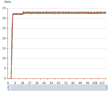
Method 2
· Verification conditions: Servers connected to a group of leaf devices and servers connected to the same leaf device group and other leaf device groups send traffic to each other. The packet length is 256 bytes.
· Verification results: The traffic speeds are as shown in Figure 15. No traffic is lost, the traffic speed is stable, and ECN takes effect throughout the process. PFC actions are triggered multiple times. However, ECN preferentially takes effect generally.

In all, no RDMA traffic is lost during the whole process, the traffic speeds fluctuate normally, and ECN preferentially takes effect over PFC to control the traffic speeds.
