- Released At: 31-07-2025
- Page Views:
- Downloads:
- Related Documents
-
H3C AC Dual-Link Backup and AP License Synchronization Best Practices
Copyright © 2023 New H3C Technologies Co., Ltd. All rights reserved.
No part of this manual may be reproduced or transmitted in any form or by any means without prior written consent of New H3C Technologies Co., Ltd.
Except for the trademarks of New H3C Technologies Co., Ltd., any trademarks that may be mentioned in this document are the property of their respective owners.
This document provides generic technical information, some of which might not be applicable to your products.
The information in this document is subject to change without notice.
Introduction
Background
As wireless technology advances, the variety of services increases, leading to heavier traffic loads on wireless network equipment. In centralized forwarding, the AC handles not only the state maintenance data for all APs in the network, various business calculations, and decision-making processes, but also a large amount of data forwarding at the aggregation layer. If the AC fails, the entire wireless network service will be disrupted, causing widespread business paralysis. As a result, a single AC device managing a wireless network is no longer sufficient to meet the current high-reliability demands of wireless networks.
Application scenarios
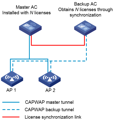
Considering configuration and cost in a dual-link backup network, licenses are installed only on the master AC. The backup AC uses licenses installed on the master AC through AP license synchronization.
Network model
In a dual-link backup network configured with AP license synchronization, each AP has two uplinks: the master Control And Provisioning of Wireless Access Point (CAPWAP) tunnel and the backup CAPWAP tunnel.
· Master and backup tunnels—Tunnels established between an AP and the master and backup ACs based on the CAPWAP protocol. The tunnel in active state is called the master tunnel, which can receive configurations deployed by the master AC and report AP service data. The other tunnel is called the backup tunnel. The establishment of the backup tunnel relies on the master tunnel.
· AC roles—The AC connected to an AP through the master tunnel is the master AC, which is responsible for AP configuration deployment and management control. The AC connected to an AP through the backup tunnel is the backup AC.
· License synchronization—Enables the master AC to synchronize local licenses to the backup AC that is not installed with licenses.
Figure 1 AP license synchronization in dual-link backup

|
|
NOTE: Besides providing redundancy, dual-link backup also allows different ACs to share the workload. For example, you can configure a group of APs to establish master tunnels with AC 1 and another group of APs to establish master tunnels with AC 2 for AC 1 and AC 2 to share the workload. |
Implementation mechanism
Dual-link backup
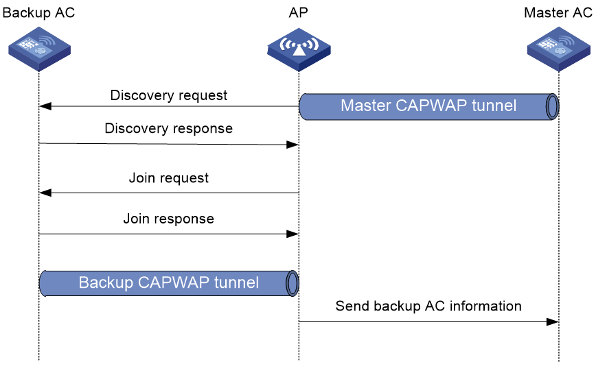
Backup tunnel establishment
For APs to establish backup tunnels, you must first specify the IP address of the backup AC on the master AC. You can specify the address for AP groups.
An AP establishes the backup tunnel as follows:
1. The AP establishes the master tunnel with the master AC.
2. The AP obtains the IP address of the backup AC from the master AC.
3. The AP sends discovery requests to the backup AC. Except the tunnel attribute, all attributes carried in the requests are the same as the attributes sent to the master AC.
4. The backup AC sends a discovery response.
5. The AP and the backup AC establishes a backup tunnel.
Figure 2 Backup tunnel establishment
You can view backup tunnel AP information or configure APs from the backup AC. The master and backup ACs must use the same configurations, except for dual-link configuration.
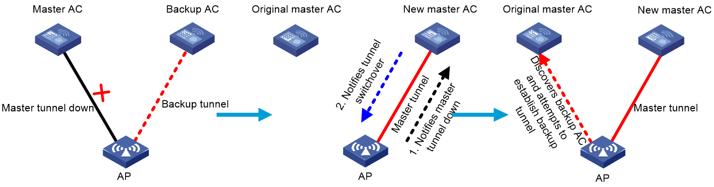
Master/backup switchover
An AP sends keepalive packets to the master AC at specific intervals to detect tunnel connectivity. Upon detecting network errors, the AP triggers a master/backup switchover. A network error can occur when the master AC fails or a user manually logs off the AP. The switchover operates as follows:
1. The AP notifies the backup AC of the master tunnel failure.
2. Upon receiving the notification, the backup AC synchronizes data between service modules, changes its role to master, and then notifies the AP of the switchover.
3. Upon receiving the tunnel switchover message, the AP destroys the master tunnel control data block, changes the control data block for the backup tunnel to be the control data block for the master tunnel, and adjusts wireless services. The original backup tunnel becomes the master tunnel.
4. The new master AC takes over wireless services. Then, the AC can deploy user configurations to the AP and process service data reported by the AP.
5. If the new master AC has a backup AC, the AP attempts to establish a backup tunnel with the backup AC.
All APs associated with the faulty AC perform the switchover. Thus, the entire network tunnels are switched and wireless services are restored.
Figure 3 Master/backup switchover
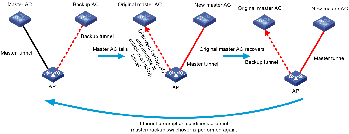
Tunnel preemption
In a dual-link backup network, by default, the backup AC tunnel becomes the master tunnel only after the master AC fails. Tunnel preemption enables the backup tunnel that has a higher priority than the master tunnel to become the master tunnel even if the master AC operates correctly.
You can configure this feature as follows for services to be switched back to the original master AC after the AC recovers:
1. Enable tunnel preemption on the original master AC.
2. Set a higher tunnel priority for the original master AC than the backup AC (new master AC).
Figure 4 Tunnel preemption
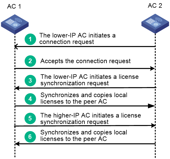
AP license synchronization
When both ACs are configured with the AP license synchronization feature, an AP license synchronization connection is established between them by using the following procedure:
1. The AC with the lower IP address initiates a connection request to the AC with the higher IP address. In this example, AC 2 initiates a connection request to AC 1.
2. AC 1 compares the license synchronization group configuration in the received request packet with the local license synchronization group configuration. If a match is found, AC 1 accepts the connection request.
3. When the connection is established, the AC with the lower IP address initiates a license synchronization request. In this example, AC 2 initiates a license synchronization request.
4. AC 1 synchronizes the local license information to AC 2 and copies local activation files to AC 2.
5. The AC with the higher IP address initiates a license synchronization request. In this example, AC 1 initiates a license synchronization request.
6. AC 2 synchronizes the local license information to AC 1 and copies local activation files to AC 1.
Figure 5 AP license synchronization
Dual-link backup and AP license synchronization
In a dual-link backup network configured with AP license synchronization, the following restrictions and guidelines apply:
· Licenses are installed only on the master AC. The backup AC does not require license installation.
· Each AP maintains a master CAPWAP tunnel and a backup CAPWAP tunnel. The master tunnel requires license resources but the backup tunnel does not. The backup tunnel requires license resources only after it is switched to the master tunnel.
· The backup AC obtains licenses installed on the master AC through AP license synchronization.
· After a master/backup switchover, the licenses on the faulty master AC continue to function on the new master AC switched from the backup AC for a 30-day grace period to ensure service continuity. For the license to take effect after that grace period, remove the issue and connect the two ACs within 30 days.
· With tunnel preemption configured, the system switches services back to the original master AC after the AC recovers.
Figure 6 AP license synchronization in a dual-link backup network
Solution deployment
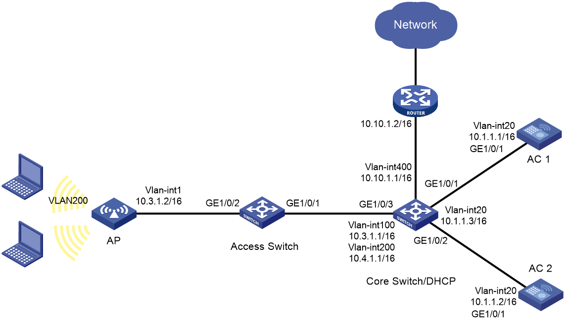
Network requirements
As shown in Figure 7, the AP connects to AC 1 and AC 2 through the access switch and the core switch.
· Configure dual-link backup and use AC 1 as the master AC and AC 2 as the backup AC. When AC 1 fails, make sure AC 2 can take over services. After AC 1 recovers, make sure services can be switched back to AC 1.
· Install licenses only on AC 1 and configure AP license synchronization for AC 2 to obtain license resources from AC 1.
· Allow clients to access the WLAN in VLAN 200.
· Configure the AP to connect to both ACs at Layer 3, and configure the AP to obtain the ACs' IP addresses through DHCP Option 43.
|
|
NOTE: This example uses centralized forwarding. You can use local forwarding as needed. |
Procedures
Configuring AC 1
1. Install licenses. (Details not shown.)
2. Configure AC interfaces:
# Create VLAN 20 and VLAN-interface 20, assign an IP address to the VLAN interface. The AP will use this IP address to establish a CAPWAP tunnel with the AC.
<AC1> system-view
[AC1] vlan 20
[AC1-vlan20] quit
[AC1] interface vlan-interface 20
[AC1-Vlan-interface20] ip address 10.1.1.1 16
[AC1-Vlan-interface20] quit
# Create VLAN 200. AC 1 will use this VLAN to forward data packets of wireless clients.
[AC1] vlan 200
[AC1-vlan200] quit
# Specify GigabitEthernet 1/0/1 that connects the AC to the switch as a trunk port and assign the port to all VLANs.
[AC1] interface gigabitethernet 1/0/1
[AC1-GigabitEthernet1/0/1] port link-type trunk
[AC1-GigabitEthernet1/0/1] port trunk permit vlan all
[AC1-GigabitEthernet1/0/1] quit
3. Configure Layer 3 routing:
# Create a static route, and specify the IP address of the core switch as the next hop.
[AC1] ip route-static 0.0.0.0 0 10.1.1.3
4. Configure dual-link backup:
# Create AP group group1, and set the AP connection priority to 7.
[AC1] wlan ap-group group1
[AC1-wlan-ap-group-group1] priority 7
# Specify the IP address of the backup AC as 10.1.1.2.
[AC1-wlan-ap-group-group1] backup-ac ip 10.1.1.2
# Configure CAPWAP tunnel preemption.
[AC1-wlan-ap-group-group1] wlan tunnel-preempt enable
[AC1-wlan-ap-group-group1] quit
5. Configure AP license synchronization.
[AC1] wlan ap-license-group
[AC1-wlan-als-group] local ip 10.1.1.1
[AC1-wlan-als-group] member ip 10.1.1.2
[AC1-wlan-als-group] ap-license-synchronization enable
[AC1-wlan-als-group] quit
6. Configure wireless services:
# Create service template 1 and enter its view.
[AC1] wlan service-template 1
# Specify the SSID as service.
[AC1-wlan-st-1] ssid service
# Specify VLAN 200 for clients coming online through the service template.
[AC1-wlan-st-1] vlan 200
# Set the AKM mode to psk and specify the plaintext preshared key as 12345678.
[AC1-wlan-st-1] akm mode psk
[AC1-wlan-st-1] preshared-key pass-phrase simple 12345678
# Specify the CCMP cipher suite and the RSN security IE.
[AC1-wlan-st-1] cipher-suite ccmp
[AC1-wlan-st-1] security-ie rsn
# Enable the service template.
[AC1-wlan-st-1] service-template enable
[AC1-wlan-st-1] quit
7. Configure the AP:
# Create AP ap1, and specify the AP model and serial ID.
[AC1] wlan ap ap1 model WA6320
[AC1-wlan-ap-ap1] serial-id 219801A28N819CE0002T
[AC1-wlan-ap-ap1] quit
8. Configure an AP group:
# Add AP ap1 to AP group group1.
[AC1] wlan ap-group group1
[AC1-wlan-ap-group-group1] ap ap1
9. Bind the service template to a radio:
# Bind service template 1 to radio 2 in AP group group1.
[AC1-wlan-ap-group-group1] ap-model WA6320
[AC1-wlan-ap-group-group1-ap-model-WA6320] radio 2
[AC1-wlan-ap-group-group1-ap-model-WA6320-radio-2] service-template 1
# Enable radio 2.
[AC1-wlan-ap-group-group1-ap-model-WA6320-radio-2] radio enable
[AC1-wlan-ap-group-group1-ap-model-WA6320-radio-2] quit
[AC1-wlan-ap-group-group1-ap-model-WA6320] quit
Configuring AC 2
1. Configure AC interfaces:
# Create VLAN 20 and create VLAN-interface 20, and assign an IP address to the interface. The AP will use this IP address to establish a CAPWAP tunnel with AC 2.
<AC2> system-view
[AC2] vlan 20
[AC2-vlan20] quit
[AC2] interface Vlan-interface 20
[AC2-Vlan-interface20] ip address 10.1.1.2 16
[AC2-Vlan-interface20] quit
# Create VLAN 200. AC 2 will use this VLAN to forward client data packets.
[AC2] vlan 200
[AC2-vlan200] quit
# Specify interface GigabitEthernet 1/0/1 that connects the AC to the switch as a trunk port, and assign the port to all VLANs.
[AC2] interface gigabitethernet 1/0/1
[AC2-GigabitEthernet1/0/1] port link-type trunk
[AC2-GigabitEthernet1/0/1] port trunk permit vlan all
[AC2-GigabitEthernet1/0/1] quit
2. Configure Layer 3 routing:
# Create a static route, and specify the IP address of the core switch as the next hop.
[AC2] ip route-static 0.0.0.0 0 10.1.1.3
3. Configure dual-link backup:
# Create AP group group1 and specify the IP address of the backup AC as 10.1.1.1. Retain the default AP connection priority.
[AC2] wlan ap-group group1
[AC2-wlan-ap-group-group1] backup-ac ip 10.1.1.1
[AC2-wlan-ap-group-group1] quit
4. Configure AP license synchronization.
[AC2] wlan ap-license-group
[AC2-wlan-als-group] local ip 10.1.1.2
[AC2-wlan-als-group] member ip 10.1.1.1
[AC2-wlan-als-group] ap-license-synchronization enable
[AC2-wlan-als-group] quit
5. Configure wireless services:
# Create service template 1 and enter its view.
[AC2] wlan service-template 1
# Specify the SSID as service.
[AC2-wlan-st-1] ssid service
# Specify VLAN 200 for clients coming online through the service template.
[AC2-wlan-st-1] vlan 200
# Set the AKM mode to psk and specify the plaintext preshared key as 12345678.
[AC2-wlan-st-1] akm mode psk
[AC2-wlan-st-1] preshared-key pass-phrase simple 12345678
# Specify the CCMP cipher suite and the RSN security IE.
[AC2-wlan-st-1] cipher-suite ccmp
[AC2-wlan-st-1] security-ie rsn
# Enable the service template.
[AC2-wlan-st-1] service-template enable
[AC2-wlan-st-1] quit
6. Configure the AP:
# Create AP ap1, and specify the AP model and serial ID.
[AC2] wlan ap ap1 model WA6320
[AC2-wlan-ap-ap1] serial-id 219801A28N819CE0002T
[AC2-wlan-ap-ap1] quit
7. Configure an AP group:
# Add AP ap1 to AP group group1.
[AC2] wlan ap-group group1
[AC2-wlan-ap-group-group1] ap ap1
8. Bind the service template to a radio:
# Bind service template 1 to radio 2 in AP group group1.
[AC2-wlan-ap-group-group1] ap-model WA6320
[AC2-wlan-ap-group-group1-ap-model-WA6320] radio 2
[AC2-wlan-ap-group-group1-ap-model-WA6320-radio-2] service-template 1
# Enable radio 2.
[AC2-wlan-ap-group-group1-ap-model-WA6320-radio-2] radio enable
[AC2-wlan-ap-group-group1-ap-model-WA6320-radio-2] quit
[AC2-wlan-ap-group-group1-ap-model-WA6320] quit
Configuring the core switch
1. Configure the core switch interfaces:
# Create VLANs 100 and 20, and assign IP addresses to VLAN-interface 100 and VLAN-interface 20. The switch will uses the VLANs to forward CAPWAP tunnel traffic.
<Core Switch> system-view
[Core Switch] vlan 100
[Core Switch-vlan100] quit
[Core Switch] interface vlan-interface 100
[Core Switch-Vlan-interface100] ip address 10.3.1.1 16
[Core Switch-Vlan-interface100] quit
[Core Switch] vlan 20
[Core Switch-vlan20] quit
[Core Switch] interface vlan-interface 20
[Core Switch-Vlan-interface20] ip address 10.1.1.3 16
[Core Switch-Vlan-interface20] quit
# Create VLAN 200 and VLAN-interface 200, and assign an IP address to the interface. Clients will use this VLAN to access the WLAN.
[Core Switch] vlan 200
[Core Switch-vlan200] quit
[Core Switch] interface vlan-interface 200
[Core Switch-Vlan-interface200] ip address 10.4.1.1 16
[Core Switch-Vlan-interface200] quit
# Specify interface GigabitEthernet 1/0/1 that connects the core switch to AC 1 as a trunk port, and assign the port to all VLANs.
[Core Switch] interface gigabitethernet 1/0/1
[Core Switch-GigabitEthernet1/0/1] port link-type trunk
[Core Switch-GigabitEthernet1/0/1] port trunk permit vlan all
[Core Switch-GigabitEthernet1/0/1] quit
# Specify interface GigabitEthernet 1/0/2 that connects the core switch to AC 2 as a trunk port, and assign the port to all VLANs.
[Core Switch] interface gigabitethernet 1/0/2
[Core Switch-GigabitEthernet1/0/2] port link-type trunk
[Core Switch-GigabitEthernet1/0/2] port trunk permit vlan all
[Core Switch-GigabitEthernet1/0/2] quit
# Specify interface GigabitEthernet 1/0/3 that connects the core switch to the access switch as a trunk port, and assign the port to all VLANs.
[Core Switch] interface gigabitethernet 1/0/3
[Core Switch-GigabitEthernet1/0/3] port link-type trunk
[Core Switch-GigabitEthernet1/0/3] port trunk permit vlan all
[Core Switch-GigabitEthernet1/0/3] quit
2. Configure DHCP:
# Configure DHCP address pool 100, specify the address range as 10.3.0.0/16, and specify the gateway address as 10.3.1.1. The switch will use this pool to assign an IP address to the AP.
[Core Switch] dhcp server ip-pool 100
[Core Switch-dhcp-pool-100] network 10.3.0.0 mask 255.255.0.0
[Core Switch-dhcp-pool-100] gateway-list 10.3.1.1
# Specify the content of Option 43. The content is the IP address of AC 1 and the IP address of AC 2 in hexadecimal notation.
[Core Switch-dhcp-pool-100] option 43 hex 800b0000020a0101010a010102
[Core Switch-dhcp-pool-100] quit
# Configure DHCP address pool 2, specify the address range as 10.4.0.0/16, specify the DNS server address, and specify the gateway address as 10.4.1.1. The switch will use this pool to assign an IP address to the client. In this example, the gateway also acts as the DNS server.
[Core Switch] dhcp server ip-pool 2
[Core Switch-dhcp-pool-2] network 10.4.0.0 mask 255.255.0.0
[Core Switch-dhcp-pool-2] gateway-list 10.4.1.1
[Core Switch-dhcp-pool-2] dns-list 10.4.1.1
[Core Switch-dhcp-pool-2] quit
# Enable the DHCP service.
[Core Switch] dhcp enable
3. Configure external network connections:
# Create VLAN 400 and VLAN-interface 400, and assign an IP address to the interface. The switch will use this VLAN to forward traffic to the external network.
[Core Switch] vlan 400
[Core Switch-vlan400] quit
[Core Switch] interface vlan-interface 400
[Core Switch-Vlan-interface400] ip address 10.10.1.1 16
[Core Switch-Vlan-interface400] quit
# Specify interface GigabitEthernet 1/0/4 that connects the core switch to the external network as an access port, and assign the port to VLAN 400.
[Core Switch] interface gigabitethernet 1/0/4
[Core Switch-GigabitEthernet1/0/4] port link-type access
[Core Switch-GigabitEthernet1/0/4] port access vlan 400
[Core Switch-GigabitEthernet1/0/4] quit
# Create a static route, and specify the IP address of the router as the next hop.
[Core Switch] ip route-static 0.0.0.0 0 10.10.1.2
Configuring the access switch
# Create VLAN 100. The switch will use this VLAN for AP access.
<Access Switch> system-view
[Access Switch] vlan 100
[Access Switch-vlan100] quit
# Specify interface GigabitEthernet 1/0/1 that connects the access switch to the core switch as a trunk port, and assign the port to all VLANs.
[Access Switch] interface gigabitEthernet 1/0/1
[Access Switch-GigabitEthernet1/0/1] port link-type trunk
[Access Switch-GigabitEthernet1/0/1] port trunk permit vlan all
[Access Switch-GigabitEthernet1/0/1] quit
# Specify interface GigabitEthernet 1/0/2 that connects the access switch to the AP as an access port, and assign the port to VLAN 100.
[Access Switch] interface gigabitethernet 1/0/2
[Access Switch-GigabitEthernet1/0/2] port link-type access
[Access Switch-GigabitEthernet1/0/2] port access vlan 100
# Enable PoE on GigabitEthernet 1/0/2.
[Access Switch-GigabitEthernet1/0/2] poe enable
[Access Switch-GigabitEthernet1/0/2] quit
Verifying the configuration
1. Use display wlan ap-license-group on AC 1 to verify that the AP license synchronization group has been established and the total number of licenses is the sum of licenses installed on AC 1 and AC 2.
<AC1> display wlan ap-license-group
Group total licenses: 256
Group used licenses: 1
AP license synchronization: Enabled
Local IP: 10.1.1.1
Local role: Master
Member information: 1
IP address Total Used Member role State Online duration
10.1.1.2 0 0 Master UP 00hr 1min 51sec
2. Use display wlan ap all on AC 1 and verify that the AP state is R/M.
<AC1> display wlan ap all
Total number of APs: 1
Total number of connected APs: 1
Total number of connected manual APs: 1
Total number of connected auto APs: 0
Total number of connected common APs: 1
Total number of connected WTUs: 0
Total number of inside APs: 0
Maximum supported APs: 384
Remaining APs: 383
Total AP licenses: 256
Local AP licenses: 256
Server AP licenses: 0
Remaining local AP licenses: 255
Sync AP licenses: 0
AP information
State : I = Idle, J = Join, JA = JoinAck, IL = ImageLoad
C = Config, DC = DataCheck, R = Run, M = Master, B = Backup
AP name AP ID State Model Serial ID
ap1 1 R/M WA6320 219801A28N819CE0002T
3. Use display wlan ap all on AC 2 and verify that the AP state is R/B and the number of synchronized licenses is 256.
<AC2> display wlan ap all
Total number of APs: 1
Total number of connected APs: 1
Total number of connected manual APs: 1
Total number of connected auto APs: 0
Total number of connected common APs: 1
Total number of connected WTUs: 0
Total number of inside APs: 0
Maximum supported APs: 384
Remaining APs: 383
Total AP licenses: 256
Local AP licenses: 256
Server AP licenses: 0
Remaining local AP licenses: 256
Sync AP licenses: 256
AP information
State : I = Idle, J = Join, JA = JoinAck, IL = ImageLoad
C = Config, DC = DataCheck, R = Run, M = Master, B = Backup
AP name AP ID State Model Serial ID
ap1 1 R/B WA6320 219801A28N819CE0002T
4. Shut down Vlan-interface 20 on AC 1. Wait for a period of time (30 seconds by default, the time varies by CAPWAP tunnel keepalive interval), and use display wlan ap all on AC 2 to verify that the AP state is R/M.
<AC2> display wlan ap all
Total number of APs: 1
Total number of connected APs: 1
Total number of connected manual APs: 1
Total number of connected auto APs: 0
Total number of connected common APs: 1
Total number of connected WTUs: 0
Total number of inside APs: 0
Maximum supported APs: 384
Remaining APs: 383
Total AP licenses: 256
Local AP licenses: 256
Server AP licenses: 0
Remaining local AP licenses: 255
Sync AP licenses: 256
AP information
State : I = Idle, J = Join, JA = JoinAck, IL = ImageLoad
C = Config, DC = DataCheck, R = Run, M = Master, B = Backup
AP name AP ID State Model Serial ID
ap1 1 R/M WA6320 219801A28N819CE0002T
5. Bring up Vlan-interface 20 on AC 1. Wait for a period of time for the AP to come online from AC 1 again. Then, use display wlan ap all to verify that the AP state is R/M on AC 1 and verify that the AP state is R/B on AC 2.
6. Use display wlan client on AC 1 to view client information. Verify that a client has connected to radio 2 of the AP.
<AC1> display wlan client
Total number of clients: 1
MAC address User name AP name R IP address VLAN
90b9-311a-bef6 N/A ap1 2 10.4.1.2 200
Restrictions and guidelines
· In dual-link backup, make sure the ACs are the same model and use the same software version.
· Use the serial ID labeled on the AP's rear panel to specify an AP.
· To configure APs manually, make sure the two ACs are configured with the same AP names and are both configured with AP serial IDs or MAC addresses.
· Before configuring services, install licenses on the AC. In dual-link backup, as a best practice for configuration convenience, install licenses only on the master AC and configure AP license synchronization. After the master AC fails, the licenses are still available for the backup AC.
· For AP license synchronization to be enabled successfully, make sure you have configured an IP address for the local AC and configure the IP addresses of member ACs before enabling AP license synchronization.
· In dual-link backup, set the roles of both ACs to master in the AP license synchronization group.
· In dual-link backup configured with AP license synchronization, if an AC is disconnected for over 30 days, licenses installed on the AC become unavailable for the other AC in the synchronization group. New APs cannot use the synchronized licenses to come online, but online APs are not affected.
Recommended device models
Table 1 lists ACs recommended for dual-link backup and AP license synchronization.
Table 1 Recommended ACs for dual-link backup and AP license synchronization
|
Product model |
Software version |
|
WX2800X series |
· WX2812X:E5617 or later · WX2860X、WX2880X:R5617 or later |
|
WX3800X series |
E1205P01 or later |
|
WX5800X series |
R5463P01 or later |
