Country / Region
H3C BBU5200 is a baseband processing unit newly developed driven by mobile communication network development. It can be deployed in an edge equipment room and offers in-depth customization, standard development, and standardization of telecom applications. It improves business agility and efficiency, and can meet the business requirements of multi-access edge computing (MEC).
The BBU5200 can be used with outdoor RRUs as the BBU for outdoor micro base stations. It can also serve as the BBU for indoor distributed wireless mobile communication systems, and can be used in scenarios including high traffic volume, indoor hotspot expansion, and coverage supplementation for blind spots. The BBU5200 is mainly responsible for cell management, system message broadcasting and updating, mobility management, wireless resource control and management, packet processing, baseband signal modulation and demodulation, management and monitoring of FSW and pRRU devices.
The BBU5200 supports both NR and LTE mode and enables integration of NR and LTE network modes on the base station side, sharing of site resources, and unified O & M, which meets the requirements of carriers for multiple network modes and allows evolution of a based station from a single network mode to multiple network modes.
The following contents are complex, and it is recommended to browse on PC.
Enter c.h3c.com.cn on the PC browser and operate according to the page to synchronize to the PC and continue browsing.
Continue by mobile
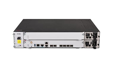
The BBU5200 supports both NR andLTE network mode, and allows flexible configuration of the NR and LTE network modes, and enables integration and concurrent working of the two network modes. This product can implement co-location coverage for both LTE and NR networks.
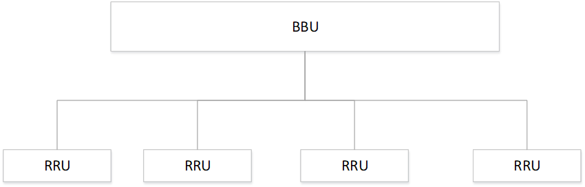
For outdoor scene: Per BBU can connect 4 RRUs.
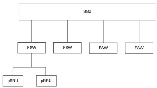
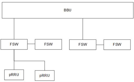
For indoor scene: FSWs and pRRUs can be connected by using star topology. Each BBU can connect to a maximum of 32 pRRUs through FSWs.
In early deployment, the system combines the radio frequency units and BBUs in different cells to form a large cell. After combination, the cell edges become part of the cell center. This effect reduces interference and improves coverage.
This product supports forming a logical cell with multiple pRRUs under the same BBU. The BBU and FSW replicate and send the signal to all pRRUs within the same cell in the downlink direction. In the uplink direction, uplink RF combination or baseband combination is supported. For uplink RF combination, the FSW merges digital signals before sending them to the upper-level FSW or BBU. For baseband combination, each uplink signal is independently demodulated in the BBU before merging. For outdoor scenarios, all uplink RF data can be merged in the baseband.
During subsequent deployments, if there is an increased demand for capacity, cell split can be performed to enhance the overall throughput within the coverage area. Co-channel interference coordination technology can be used to solve interference issues at the cell edges.
Interference is a critical challenge in networks with co-frequency deployment. In practical networks, some users, specifically at the cell edges, often experience very low Signal to Interference plus Noise Ratio (SINR). As a result, higher-order modulations cannot be used, and the advantages of 5G cannot be presented. This product supports Coordinated Multi-Point (CoMP) processing through baseband combination to enhance the performance at the cell edges. In addition, it uses appropriate power control and Interference Rejection Combining (IRC) algorithms to suppress and eliminate interference.
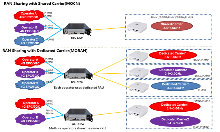
A set of base station equipment, multiple operators can deploy independent networks on it (up to 6 operators), and it supports PLMN-based network parameter configuration and optimization, as well as PLMN-based QoS and slicing services. RAN Sharing meet the requirement of multi-operator’s co-construction and sharing and reduce CAPEX and OPEX.
Network slicing transforms a network into a set of logical networks on top of shared infrastructure to meet diversified business requirements.
The BBU5200 supports service slice awareness. It can sense the service slice type based on the slice ID to provide differentiated QoS guarantee. If necessary, you can set the priority of a slice to absolutely high to ensure absolute priority scheduling of the service slice.
Slice-based resource isolation allows you to configure slice user groups to reserve radio resources for specific slices and for users of each slice based on PRB. The remaining resources (such as frequency flexible bandwidth) can be shared by other slice users, which can increase the flexibility of spectrum utilization while ensuring the QoS of slicing services.
Item | Specifications |
Management port on the NR control and baseband unit | 1, RJ-45 |
USB port (per MPU) | 1, USB2.0 |
Console port on the NR control and baseband unit | 1, RJ-45 |
GNSS port on the NR control and baseband unit | 1 |
PPS/ToD port on the NR control and baseband unit | 2 |
Backhaul port on the NR control and baseband unit | 2 × SFP+, support for 1GE and 10GE transceiver modules |
Fronthaul port on the NR control and baseband unit | 4 × eCPRI, support for 10GE and 25GE transceiver modules |
Power supply | 2 × 780 W. Each BBU5200 supports two removable AC or DC power supplies. Available power supplies: 780W AC power supply and 780W DC power supply. |
Fan tray | 1, MCBE2FANC |
Dimensions (H × W × D) | 88 × 440 × 333 mm (3.46 × 17.32 × 13.11 in) |
NR control and baseband module | 1, MCBM1NBBPD1 |
LTE baseband module | 1, MCBM1LBBPE0 |
Operating temperature | –5°C to +55°C (23°F to 131°F) |
Storage temperature | –40°C to +70°C (–40°F to +158°F) |
Operating temperature change | 20°C (36°F) per hour |
Storage temperature change | 30°C (54°F) per hour |
Operating relative humidity (noncondensing) | 5% to 95% |
Storage relative humidity (noncondensing) | 5% to 95% |
Operating altitude | –60 m to +5000 m (–196.85 to +16404.20 ft) The maximum temperature decreases by 0.33 °C (32.59°F) as the altitude increases by 100 m (328.08 ft) from 0 m (0 ft). |
Storage altitude | –60 m to +5000 m (–196.85 to +16404.20 ft) |
Feature | Capacity |
Users per TTI | 8 |
Maximum cells | Four 2T2R cells each with 100-MHz bandwidth, or two 4T4R cells each with 100-MHz bandwidth. |
Maximum connected users per cell | 1200 |
Maximum active users per cell | 400 |
Maximum bears per cell | 400 × 3 |
Maximum bears per user | 8 |
Maximum capacity per base station | 4800 × 3 |
Maximum number of PDU sessions per base station | 4800 × 3 |
Maximum number of QoS flows per base station | 4800 × 3 |
Maximum SCTP connections | 64 |
Maximum neighboring cells per cell | 128 |
Topology | Indoor:
Outdoor: Star topology. |
Feature | Capacity |
Users per TTI | 8 |
Maximum cells | 1 2T2R cell. Each cell can support the baseband combination of up to four physical cells. |
Maximum connected users per cell | 400 |
Maximum active users per cell | 400 |
Maximum bears per cell | 400 × 3 |
Maximum bears per user | 8 |
Maximum capacity per base station | 400 × 3 |
Maximum number of X2 interfaces | 32 |
Maximum number of S1 interfaces | 32 |
Maximum neighboring cells per cell | 16 |
Maximum number of neighbor cells per site | 64 |
Networking | Indoor:
Outdoor: Star topology. |
Item | Specifications |
3GPP version | Rel-15 |
System bandwidth | 100 MHz |
Frame format | 30 KHz subcarrier spacing 5 ms single periodicity (7D1S2U) 2.5 ms dual periodicity (3D1S1U 2D1S2U) 2.5 ms single periodicity (1D1S3U) |
System parameters | Two BWPs CP-OFDM waveform on both uplinks and downlinks |
Physical channels | SSB, PDCCH, and PDSCH downlink physical channels PRACH, PUCCH, and PUSCH uplink physical channels |
Reference signal | Synchronization signal block Demodulation reference signal SRS CSI-RS |
QoS | Non-GBR services GBR services Scheduling based on QoS parameters such as maximum bit rate (MBR), guaranteed bit rate (GBR), UE-AMBR, 5QI, and MFBR Allocation and retention priority (ARP) |
Cell management | Cell establishment Cell release Cell reconfiguration Cell combination and splitting |
Uplink MIMO transmission | 2×2 SU-MIMO |
Downlink MIMO transmission | 2×2 SU-MIMO 4×4 SU-MIMO |
Dynamic scheduling | Service-based QoS scheduling RR algorithm BSR reporting based on terminal caching status |
Transmission mode | Codebook-based uplink transmission mode Downlink transmission based on PMI feedback |
Wireless bearers | Signaling bearers: SRB0, SRB1, SRB2 Data bearers: AM DRB, UM DRB |
HARQ | Incremental redundancy (IR) algorithm and at least four redundant versions 16 downlink HARQ processes and 16 uplink HARQ processes per user |
Power management and assignment | Downlink power assignment and uplink power control Open loop power control (OLPC) Closed loop power control (CLPC) for PUSCH CLPC for PUCCH Power headroom reporting |
Link adaptation | Link adaptation on uplinks: QPSK, 16QAM, 64QAM, 256QAM Link adaptation on downlinks: QPSK, 16QAM, 64QAM, 256QAM Automatic modulation code level adjustment based on channel quality |
Random access | Contention-based random access Non-contention based random access |
Base station synchronization | GPS BeiDou IEEE 1588v2 |
Measurement | A1, A2, A3, A4, B1, and B2 measurement control and reporting |
RRC connection control | Establishment, reconfiguration, re-establishment, and release of RRC connections Establishment, reconfiguration, and release of data carriers |
Paging | Core-side paging |
Mobility | System message-based cell selection and reselection Intra-system intra-frequency switchover through the Xn interface Intra-system inter-frequency switchover through the NG interface Switching between 4G and 5G |
Encryption and decryption | EEA0: NULL EEA1: SNOW3G EEA2: AES EEA3: ZUC |
Integrity protection | EIA0: NULL EIA1: SNOW3G EIA2: AES EIA3: ZUC |
Network slicing | Service slicing awareness based on slice IDs AMF selection based on slice IDs Radio-side resource isolation based on slice user groups, which means reserving radio resources for specific slices and for users of each slice based on PRB QoS differentiated guarantee in a slice |
Networking | SA Option 2 Frame header offset configuration in a hybrid 4G and 5G network |
Voice service | Voice service through EPS fallback |
NG interface | NG interface protocols |
Xn interface | Xn interface protocols |
eCPRI interfaces | 4 × eCPRI interfaces operating at 25 Gbps |
Item | Specifications |
3GPP version | Rel-15 |
System bandwidth | 5/10/15/20 MHz |
Subcarrier spacing | 15 KHz |
Physical channels | Primary synchronization channel (P-SCH), secondary synchronization channel (S-SCH) All physical channels including PUSCH, PUCCH, PRACH, PDSCH, PHICH, PCFICH, PDCCH, PBCH, except eMBMS-related PMCH channels |
Cell reference signal | port 0, port 1 |
QoS | Non-GBR services GBR services Scheduling based on QoS parameters such as maximum bit rate (MBR), guaranteed bit rate (GBR), UE-AMBR, 5QI, and MFBR Allocation and retention priority (ARP) |
Cell management | Cell establishment Cell release Cell reconfiguration Cell combination and splitting |
Uplink MIMO transmission | 1×1 SU-MIMO |
Downlink MIMO transmission | 2×2 SU-MIMO |
Dynamic scheduling | Service-based QoS scheduling RR algorithm BSR reporting based on terminal caching status Dynamic scheduling per TTI |
Transmission mode | Two downlink port transmit diversity SFBC (mode 2) Two downlink port open loop spatial multiplexing (mode 3) Two downlink port closed loop spatial multiplexing (mode 4) |
Wireless bearers | Signaling bearers: SRB0, SRB1, SRB2 Data bearers: AM DRB, UM DRB |
HARQ | Uplink incremental redundancy (IR) algorithm and at least four redundant versions Downlink transmission of IR algorithms and at least four redundant versions Uplink synchronous adaptive and synchronous non-adaptive HARQ Downlink asynchronous adaptive HARQ 8 uplink processes and 8 downlink processes |
Power management and assignment | Uplink power management: Closed loop power control (CLPC) for random access message 3 Open loop power control (OLPC) for PUSCH, PUCCH, and SRS CLPC for PUSCH, PUCCH, and SRS Power headroom reporting triggered periodically or by threshold-crossing events Downlink power management: Downlink power assignment for RS and PDSCH Downlink power assignment based on cell coverage |
Coding and modulation | Channel coding such as convolutional codes and turbo codes Downlink modulation: BPSK, QPSK, 16QAM, 64QAM, 256QAM Uplink modulation: BPSK, QPSK, 16QAM, 64QAM |
Link adaptation | Link adaptation on uplinks and downlinks Dynamic configuration of user transmission resources and transmission formats |
Random access | Contention-based random access Non-contention based random access |
Base station synchronization | GPS BeiDou IEEE 1588v2 |
Measurement | A1, A2, A3, A4, B1, and B2 measurement control and reporting |
System information | RRC-sent system messages to request support for system messages MIB, SIB1, SIB2, SIB3, SIB4, and SIB5 RRC-sent system messages to request support for system message SIB24 |
RRC connection control | Establishment, reconfiguration, re-establishment, and release of RRC connections Establishment, reconfiguration, and release of data carriers |
Paging | Core-side paging |
Mobility | System message-based cell selection and reselection Intra-system intra-frequency switchover through the X2 interface Intra-system inter-frequency switchover through the S1 interface Switching between 4G and 5G |
Encryption and decryption | EEA0: NULL EEA1: SNOW3G EEA2: AES EEA3: ZUC |
Integrity protection | EIA0: NULL EIA1: SNOW3G EIA2: AES EIA3: ZUC |
Networking | Frame header offset configuration in a hybrid 4G and 5G network |
S1 interface | S1 interface protocols |
X2 interface | X2 interface protocols |
eCPRI interfaces | 4 × eCPRI interfaces operating at 10 Gbps or 25 Gbps |
Item | Description | Remarks |
BBU5200 | BBU5200 Baseband Unit | Required. |
MCBM1NBBPD1 | NR Main Control and Baseband Module | Required. |
MCBM1LBBPE0 | LTE baseband Module | Optional. (Used when 4G/5G dual-mode service is required.) |
Item | Description | Remarks |
MCBE2FANB | MCBE2FANB Fan Tray | Required. Shipped with the chassis. The BBU5200 supports only this fan tray model. |
Item | Description | Remarks |
PSR780-12A | 780W AC Power Supply | Do not install AC and DC power supplies on the BBU5200. |
PSR780-12D | 780W DC Power Supply |
Transceiver module type | Transceiver module name | Central wavelength | Connector type | Max transmission distance | Remarks |
1G SFP transceiver module | SFP-GE-LX-SM1310-A | 1310 nm | LC | 10 km (6.21 miles) | Used for fronthaul ports |
SFP-GE-LX-SM1310-D | 1310 nm | 10 km (6.21 miles) | |||
SFP-GE-LX-SM1310-S | 1310 nm | 10 km (6.21 miles) | |||
10G SFP+ transceiver module | SFP-XG-LX-SM1310 | 1310 nm | LC | 10 km (6.21 miles) | Used for fronthaul and backhaul ports |
SFP-XG-LX-SM1310-D | 1310 nm | 10 km (6.21 miles) | |||
SFP-XG-LX-SM1310-S | 1310 nm | 10 km (6.21 miles) | |||
SFP-XG-CPRI-IR-SM1310 | 1310 nm | 1.4 km (0.87 miles) | |||
SFP-XG-CPRI-LR-SM1310 | 1310 nm | 10 km (6.21 miles) | |||
25G SFP28 transceiver module | SFP-25G-LR-SM1310 | 1310 nm | LC | 10 km (6.21 miles) | Used for fronthaul ports |
SFP-25G-LR-SM1310-I | 1310 nm | 10 km (6.21 miles) |