- Table of Contents
-
- 11-NAT Configuration
- 01-ER G3 Routers Port Mapping Configuration Examples (Web)
- 02-MSR Routers Port Mapping Configuration Examples (Web)
- 03-MSR Routers Configure Internal Users to Access Internal Servers by Using Public Addresses
- 04-MSR Routers Configure Internal and External Users to Access Internal Servers
- Related Documents
-
| Title | Size | Download |
|---|---|---|
| 01-ER G3 Routers Port Mapping Configuration Examples (Web) | 128.02 KB |
ERG3 Routers
Port Mapping Configuration Examples
Copyright © 2024 New H3C Technologies Co., Ltd. All rights reserved.
No part of this manual may be reproduced or transmitted in any form or by any means without prior written consent of New H3C Technologies Co., Ltd.
Except for the trademarks of New H3C Technologies Co., Ltd., any trademarks that may be mentioned in this document are the property of their respective owners.
The information in this document is subject to change without notice.
Introduction
The following information describes the port mapping configuration on the ERG3 Router Series.
For an external network user (such as an employee on business trip) that wants to access a server in the internal network of the enterprise, you can configure port mapping on the NAT Settings > Virtual Servers page of the Web interface.
Prerequisites
This document is not restricted to specific software or hardware versions. Procedures and information in the examples might be slightly different depending on the software or hardware version of the device.
The configuration examples were created and verified in a lab environment, and all the devices were started with the factory default configuration. When you are working on a live network, make sure you understand the potential impact of every command on your network.
The following information is provided based on the assumption that you have basic knowledge of virtual NAT servers.
Software versions used
This configuration example was created and verified on Release 0136 of the ER3200G3 Router Series.
Network configuration
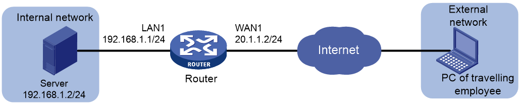
As shown in Figure 1, Router acts as the border gateway for an enterprise, and connects the Internet through interface WAN1. The connection mode of WAN1 is fixed IP, and is configured with IP address 20.1.1.2/24 and gateway address 20.1.1.1.
Configure port mapping on the router to enable employees on business trips to access the OA server on the internal network. The information of the OA server is as follows:
· Protocol type: TCP
· IP address: 192.168.1.2.
· Internal port: 80
Restrictions and guidelines
In this example, only the server's Web service port is mapped. Select the user-defined ports option for the global IP address field, and configure the start and end port numbers to be consistent. As a best practice, enter a port number of 10000 or higher. In this example, enter 10000.
Procedures
Configuring the router for network access
In this example, select the single-WAN scenario for the external network, and set the connection mode of the selected WAN interface to fixed IP.
Perform the following tasks:
1. From the navigation pane, select Network > External Networks.
2. On the Configure Interface Mode tab, select the single-WAN mode, and then click Apply.
Figure 2 Configuring the WAN scenario

3. Click the WAN Settings tab.
4. Click the Edit icon in the Actions column for WAN1.
5. Select Fixed IP from the Connection Mode list.
6. In the IP Address field, enter 20.1.1.2.
7. In the Subnet Mask field, enter 255.255.255.0.
8. In the Gateway Address field, enter 20.1.1.1.
9. Use the default settings for other parameters, and then click Apply.
Figure 3 Connecting interface WAN1 to the Internet

Configuring the virtual server (port mapping)
In this example, only the Web service of the server is mapped. Select the user-defined ports option for the global port field, and configure the start and end port numbers to be consistent. As a best practice, enter a port number of 10000 or higher.
Perform the following tasks:
1. From the navigation pane, select Network > NAT Settings.
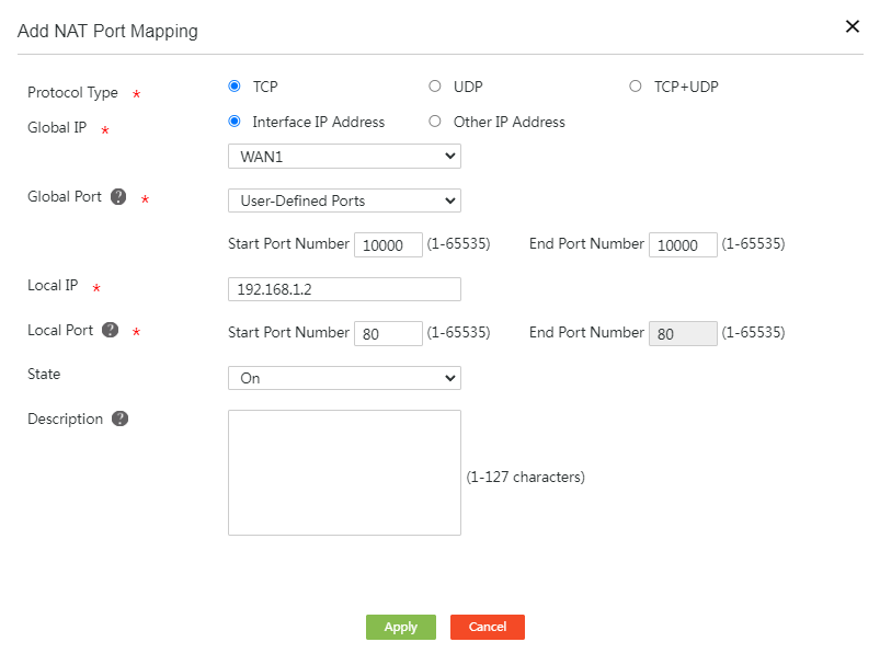
2. Click Add.
3. In the Protocol Type field, select TCP.
4. In the Global IP field, select the current IP address option.
5. From the Global Port list, select User-Defined Ports, and enter 10000 in the Start Port Number field and 10000 in the End Port Number field.
6. In the Local IP field, enter 192.168. 1.2, the IP address of the server.
7. In the Local Port field, enter 80 in the Start Port Number field and End Port Number field.
8. From the State list, select On to enable port mapping.
9. Click Apply.
Figure 4 Adding a NAT port mapping
Verifying the configuration
On the PC of a traveling employee, enter http://20.1.1.2:10000 in the browser to access the internal OA server Web page of the company. Verify that the configuration succeeds
