- Table of Contents
- Related Documents
-
| Title | Size | Download |
|---|---|---|
| 03-Internet Access Through Port-Based VLAN | 73.30 KB |
Internet Access Through Port-Based VLAN
Copyright © 2024 New H3C Technologies Co., Ltd. All rights reserved.
No part of this manual may be reproduced or transmitted in any form or by any means without prior written consent of New H3C Technologies Co., Ltd.
Except for the trademarks of New H3C Technologies Co., Ltd., any trademarks that may be mentioned in this document are the property of their respective owners.
The information in this document is subject to change without notice.
Introduction
The following information provides examples for configuring port-based VLANs to implement Internet access for a switch.
Prerequisites
This document is not restricted to specific software or hardware versions. Procedures and information in the examples might be slightly different depending on the software or hardware version of the device.
The configuration examples were created and verified in a lab environment, and all the devices were started with the factory default configuration. When you are working on a live network, make sure you understand the potential impact of every command on your network.
The following information is provided based on the assumption that you have basic knowledge of VLAN.
Configuration example
Network configuration
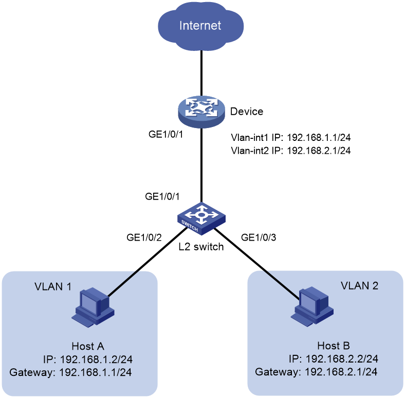
As shown in Figure 1, Host A and Host B are connected to the L2 switch. Host A belongs to VLAN 1 and Host B belongs to VLAN 2. On the device, the IP address of VLAN interface 1 is 192.168.1.1/24, and the IP address of VLAN interface 2 is 192.168.2.1/24. Configure the switch and the device to enable Host A and Host B to access the Internet.
Analysis
On the device, configure GigabitEthernet 1/0/1 as a trunk port, and assign the port to VLAN 1 and VLAN 2.
On the switch, configure GigabitEthernet 1/0/1 as a trunk port, and assign the port to VLAN 1 and VLAN 2. GigabitEthernet 1/0/2 is an access port and belongs to VLAN 1 by default.
Table 1 How ports of different link types handle frames
|
Actions |
Access |
Trunk |
|
In the inbound direction for an untagged frame |
Tags the frame with the PVID tag. |
· If the PVID is permitted on the port, tags the frame with the PVID tag. · If not, drops the frame. |
|
In the inbound direction for a tagged frame |
· Receives the frame if its VLAN ID is the same as the PVID. · Drops the frame if its VLAN ID is different from the PVID. |
· Receives the frame if its VLAN is permitted on the port. · Drops the frame if its VLAN is not permitted on the port. |
|
In the outbound direction |
Removes the VLAN tag and sends the frame. |
· Removes the tag and sends the frame if the frame carries the PVID tag and the port belongs to the PVID. · Sends the frame without removing the tag if its VLAN is carried on the port but is different from the PVID. |
Procedure
1. Configure Host A and Host B:
# Assign IP address 192.168.2.2/24 to Host A, and configure its gateway address as 192.168.2.1/24. Assign IP address 192.168.3.2/24 to Host B, and configure its gateway address as 192.168.3.1/24.
2. Configure the L2 switch:
# Create VLAN 2, and assign GigabitEthernet 1/0/3 to VLAN 2.
<L2_Switch> system-view
[L2_Switch] vlan 2
[L2_Switch-vlan2] port gigabitethernet 1/0/3
[L2_Switch-vlan2] quit
# Configure GigabitEthernet 1/0/1 as a trunk port, and assign it to VLAN 1 and VLAN 2.
[L2_Switch] interface gigabitethernet 1/0/1
[L2_Switch-GigabitEthernet1/0/1] port link-type trunk
[L2_Switch-GigabitEthernet1/0/1] port trunk permit vlan 1 to 2
3. Configure the device:
# Create VLAN interface 1, and assign IP address 192.168.1.1/24 to the interface.
<Device> system-view
[Device] vlan 1
[Device-vlan1] quit
[Device] interface vlan-interface 1
[Device-Vlan-interface1] ip address 192.168.1.1 255.255.255.0
[Device-Vlan-interface1] quit
# Create VLAN interface 2, and assign IP address 192.168.2.1/24 to the interface.
[Device] vlan 2
[Device-vlan2] quit
[Device] interface vlan-interface 2
[Device-Vlan-interface2] ip address 192.168.2.1 255.255.255.0
[Device-Vlan-interface2] quit
# Configure GigabitEthernet 1/0/1 as a trunk port, and assign it to VLAN 1 and VLAN 2.
[Device] interface gigabitethernet 1/0/1
[Device-GigabitEthernet1/0/1] port link-type trunk
[Device-GigabitEthernet1/0/1] port trunk permit vlan 1 to 2
Verifying the configuration
Verify that both Host A and Host B can access the Internet.
Configuration files
· L2 switch:
#
vlan 1
#
vlan 2
#
interface GigabitEthernet1/0/1
port link-mode bridge
port link-type trunk
port trunk permit vlan 1 to 2
#
interface GigabitEthernet1/0/2
port link-mode bridge
#
interface GigabitEthernet1/0/3
port link-mode bridge
port access vlan 2
#
· Device:
#
vlan 1
#
vlan 2
#
interface Vlan-interface1
ip address 192.168.1.254 255.255.255.0
#
interface Vlan-interface2
ip address 192.168.2.1 255.255.255.0
#
interface GigabitEthernet1/0/1
port link-mode bridge
port link-type trunk
port trunk permit vlan 1 to 2
#
Related documentation
· VLAN Configuration in H3C MSR Router Series Comware 7 Configuration Guides
· VLAN Commands in H3C MSR Router Series Comware 7 Command References
