- Table of Contents
- Related Documents
-
| Title | Size | Download |
|---|---|---|
| 01-Text | 3.84 MB |
Contents
H3C SR6600/SR6600-X router interface modules
Connecting an Ethernet interface cable
Connecting an optical interface cable
Connecting an E1 interface cable
Connecting a T1 interface cable
Connecting a CE3/CT3/T3 interface cable
Connecting a serial interface cable
Interface module technical specifications
Compatibility matrixes on Comware 5
LPU and router compatibility matrix
LPU and MPU compatibility matrix
MPU and router compatibility matrix
Compatibility matrixes on Comware 7
LPU and router compatibility matrix
LPU and MPU compatibility matrix
MPU and router compatibility matrix
Interface module and Comware compatibility matrix
Interface module and FIP compatibility matrix
Interface module&SAP and transceiver module compatibility matrix
H3C SR6600/SR6600-X router interface modules
|
|
CAUTION: You can hot swap or perform an online removal and insertion (OIR) operation on an interface module. OIR requires you to execute the remove command or press the REMOVE button before you remove an interface module, and hot-swapping does not. · MIM interface modules do not support hot swapping or OIR. · HIM interface modules support OIR. To replace a HIM interface module during device operation, you must first execute the remove command. · MIC interface modules except for MIC-X-CNDE-SJK support hot swapping. To replace a MIC-X-CNDE-SJK interface module during device operation, you must first press and hold the REMOVE button on the module until the RUN LED turns off. |
|
|
NOTE: The LPU, MPU, and router compatibility matrixes vary by Comware system. For more information, see "Compatibility matrixes on Comware 5" and "Compatibility matrixes on Comware 7." |
HIMs
HIM-8FE
The HIM-8FE is a 10BASE-T/100BASE-TX Fast Ethernet (FE) interface module used by a router to communicate with a LAN. It provides eight RJ-45 ports, each of which supports the Layer 3 routing function and has a bi-color status LED.
The HIM-8FE has the following features:
· The transmission distance can be up to 100 meters (328.08 ft) if a category-5 twisted pair cable is used.
· The interfaces support 10/100 Mbps auto-sensing.
· The interfaces typically operate in full duplex mode and can also operate in half duplex mode.
Front panel

|
(1) FE port |
(2) FE port status LED |
|
(3) Captive screw |
(4) Ejector lever |
LEDs
Table 1 LED description
|
LED status |
Description |
|
Off |
No link is present or the cable is faulty. |
|
Steady yellow |
A 10 Mbps link is present. |
|
Flashing yellow |
Data is being received or transmitted at 10 Mbps. |
|
Steady green |
A 100 Mbps link is present. |
|
Flashing green |
Data is being received or transmitted at 100 Mbps. |
Interface specifications
Table 2 Interface specifications
|
Item |
Specification |
|
Connector type |
RJ-45 |
|
Number of interfaces |
8 |
|
Interface standards |
802.3, 802.3u |
|
Interface type |
Auto MDI/MDI-X |
|
Cable type |
Straight-through/crossover cable |
|
Transmission distance |
100 m (328.08 ft) |
|
Interface speed and duplex mode |
· 10/100 Mbps auto-sensing · Full duplex/half duplex |
|
|
NOTE: The medium dependent interface (MDI) standard is typically used on the Ethernet interface of network adapters; the medium dependent interface crossover (MDI-X) standard is typically used on hubs or LAN switches. |
Interface cables
The HIM-8FE uses a category-5 straight-through cable or crossover Ethernet cable. For the appearance and connection of a HIM-8FE interface cable, see "Connecting an Ethernet interface cable."
HIM-4GBE/HIM-8GBE
The HIM-4GBE and HIM-8GBE are 10BASE-T/100BASE-TX/1000BASE-T auto-sensing Ethernet interface modules. A HIM-4GBE provides four, and a HIM-8GBE provides eight, RJ-45 ports that support Layer 3 routing. Each port is provided with a bi-color LED indicating the running status of the port. The HIM-4GBE or HIM-8GBE is connected to the processor through a 10-Gbps high-speed bus and can provide all high-performance Layer 3 Ethernet interface functionalities.
Front panels
Figure 2 Front panel of HIM-8GBE

|
(1) GE port |
(2) GE port status LED |
|
(3) Captive screw |
(4) Ejector lever |
Figure 3 Front panel of HIM-4GBE

|
(1) Captive screw |
(2) GE port |
|
(3) GE port status LED |
(4) Ejector lever |
LEDs
Table 3 LED description
|
LED status |
Description |
|
Off |
No link is present or the cable is faulty. |
|
Steady green |
A 1000 Mbps link is present. |
|
Flashing green |
Data is being received or transmitted at 1000 Mbps. |
|
Steady yellow |
A 10/100 Mbps link is present. |
|
Flashing yellow |
Data is being received or transmitted at 10/100 Mbps. |
Interface specifications
Table 4 Interface specifications
|
Item |
Specification |
|
|
Connector type |
RJ-45 |
|
|
Number of interfaces |
· HIM-4GBE: 4 · HIM-8GBE: 8 |
|
|
Interface standards |
802.3, 802.3u, 802.3ab |
|
|
Interface type |
Auto MDI/MDI-X |
|
|
Cable type |
Straight-through/crossover Ethernet cable |
|
|
Transmission distance |
100 m (328.08 ft) |
|
|
Supported frame format |
· Ethernet_II · Ethernet_SNAP |
|
|
Interface speed and duplex mode |
10 Mbps |
Full/half duplex, auto-negotiation |
|
100 Mbps |
Full/half duplex, auto-negotiation |
|
|
1000 Mbps |
Full duplex |
|
|
|
NOTE: · When 10/100 Mbps and half duplex/full duplex are specified for an Ethernet copper port, the Ethernet copper port operates in forced mode. When 1000 Mbps is specified or the interface speed and the duplex mode are not simultaneously specified for an Ethernet copper port, the port operates in auto-negotiation mode. · When operating in forced mode, an Ethernet copper port does not support auto MDI/MDI-X. · When operating in auto-negotiation mode, an Ethernet copper port supports auto MDI/MDI-X. |
Interface cables
The HIM-4GBE/HIM-8GBE uses a category-5 straight-through or crossover Ethernet cable when operating at 10/100 Mbps, and uses a category-6 cable (recommended) when operating at 1000 Mbps. For the appearance and connection of a HIM-4GBE/HIM-8GBE interface cable, see "Connecting an Ethernet interface cable."
HIM-4GBP/HIM-8GBP
The HIM-4GBP and HIM-8GBP are high-speed Layer 3 GE interface modules. A HIM-4GBP provides 4, and a HIM-8GBP provides 8 Small Form-Factor Pluggable (SFP) ports that support Layer 3 routing. Each port is provided with a bi-color LED, which indicates the running status of the port. Connected to the processor through an SPI-4 high-speed bus, the HIM-4GBP or HIM-8GBP provides a full range of high-performance functions of Layer 3 Ethernet interfaces.
Front panels
Figure 4 Front panel of HIM-4GBP

|
(1) Captive screw |
(2) SFP port |
|
(3) SFP port status LED |
(4) Ejector lever |
Figure 5 Front panel of HIM-8GBP

|
(1) Captive screw |
(2) SFP port |
|
(3) SFP port status LED |
(4) Ejector lever |
LEDs
Table 5 LED description
|
LED status |
Description |
|
Off |
No link is present. |
|
Steady green |
A 1000 Mbps link is present. |
|
Flashing green |
The interface is receiving or sending data at 1000 Mbps. |
|
Steady yellow |
A 100 Mbps link is present. |
|
Flashing yellow |
The interface is receiving or sending data at 100 Mbps. |
Interface specifications
Table 6 Interface specifications
|
Item |
Specification |
|
Connector type |
SFP |
|
Number of interfaces |
· HIM-4GBP: 4 · HIM-8GBP: 8 |
|
Interface standards |
802.3, 802.3u, 802.3ab |
|
Supported frame format |
· Ethernet_II · Ethernet_SNAP |
|
Interface speed |
· 1000 Mbps (recommended) · Full duplex |
The following transceiver modules are available for the HIM-4GBP/HIM-8GBP:
· 100 Mbps fiber SFP transceiver modules.
· 1000 Mbps fiber SFP transceiver modules.
· 100/1000 Mbps fiber SFP transceiver modules.
· 10/100/1000 Mbps copper SFP transceiver modules (support for 10/100/1000 Mbps autosensing on the HIM-4GBP/HIM-8GBP).
Prepare the transceiver modules yourself as required.
As a best practice, use H3C SFP transceiver modules for the device. H3C does not guarantee the compatibility of SFP transceiver modules from other vendors with the device. The device reports an alarm when non-H3C SFP transceiver modules are installed.
Interface cables
Use interface cables for the HIM-4GBP/HIM-8GBP as follows:
· Fiber SFP transceiver module—Fibers with the LC connector.
· Copper SFP transceiver module—Category-5 straight-through or crossover twisted pair cable when the port is operating at 10/100 Mbps and Category-6 twisted pair cable when the port is operating at 1000 Mbps.
For the appearance and connection of a HIM-4GBP/HIM-8GBP interface cable, see "Connecting an Ethernet interface cable" or "Connecting an optical interface cable."
HIM-1EXP
The HIM-1EXP is a 1-port 10 GE transceiver module. It provides one 10-Gigabit Small Form-Factor Pluggable (XFP) port and supports switchover between LAN/WAN PHY modes. A LED is provided on the front panel to show the operation state.
Front panel

|
(1) Captive screw |
(2) Ejector lever |
|
(3) XFP port |
(4) XFP port carrier signal LED (LINK/ACT) |
LED
Table 7 LED description
|
LED status |
Description |
|
Off |
No link is present. |
|
Steady green |
A link is present, but no data is being received or transmitted. |
|
Flashing green |
The XFP port is receiving or sending data. |
Interface specifications
Table 8 Interface specifications
|
Item |
Specification |
|
Connector type |
XFP/LC |
|
Number of interfaces |
1 |
|
Supported frame format |
10GBASE-R/W |
|
Interface speed |
· LAN PHY mode: 10.3125 Gbps · WAN PHY mode: 9.95328 Gbps |
|
|
NOTE: In LAN PHY mode, 10GBASE-R is supported. In WAN PHY mode, 10GBASE-W is supported. |
Interface cables
The HIM-1EXP must work with an XFP transceiver module and an optical fiber with LC-type connectors. For the appearance and connection of a HIM-1EXP interface cable, see "Connecting an optical interface cable."
HIM-CL1P/HIM-CL2P
The HIM-CL1P and HIM-CL2P are high-speed OC-3/STM-1 (155 Mbps) channelized packet over SONET/SDH (CPOS) E1/T1 interface modules. The HIM-CL1P provides one SFP port and the port is provided with two LEDs, which indicate the port running status and fault detection status, respectively. The HIM-CL2P provides two SFP ports.
The HIM-CL1P/HIM-CL2P has the following features:
· Connects to the processor through a 10-Gbps high-speed bus. Each CPOS interface can be channelized into 63 E1s or 84 T1s, and it can be channelized into 512 DS0s.
· Receives multiplexed E1/T1 circuits on a pair of fibers through a channelized interface, saving many link resources, the occupied area, and the cost of local networks and devices for telecommunication service providers and large enterprises.
· Supports IP and MPLS traffic and the Multi-link Point-to-Point Protocol (MP), and supports up to 12 E1s or T1s in each MP bundle.
· Uses hardware-based MP bundling. This solves the problem of low efficiency of MP bundling, and improving the access density of user devices.
· Supports two operating modes that can be configured at the CLI: CPOS E1 and CPOS T1.
· The operating mode configuration takes effect only after you hot-swap the interface module or reboot the device. As a best practice, remove and insert the module to bring the configuration into effect.
· Before removing a HIM interface module during device operation, execute the remove command for the module.
· The operating mode configuration takes effect for all the interfaces on the interface module.
|
|
NOTE: · The HIM-CL1P/HIM-CL2P does not support cascading and non-channelized SDH and SONET. · The HIM-CL1P/HIM-CL2P does not support channelizing OC-3/STM-1 into DS3s or E3s. |
Front panels
Figure 7 Front panel of HIM-CL1P

|
(1) SFP port carrier signal LED (LINK/ACT) |
(2) SFP port loopback/alarm LED (LP/AL) of SFP port |
|
(3) SFP port |
(4) Captive screw |
|
(5) Ejector lever |
|
Figure 8 Front panel of HIM-CL2P

|
(1) SFP port carrier signal LED (LINK/ACT) |
(2) SFP port loopback/alarm LED (LP/AL) |
|
(3) SFP port |
(4) Captive screw |
|
(5) Ejector lever |
|
LEDs
Table 9 LED description
|
LED |
Status |
Description |
|
LINK/ACT (Green) |
Off |
No link is present. |
|
On |
A 155.52 Mbps link is present. |
|
|
Flashing |
The SFP port is receiving or sending data at 155.52 Mbps. |
|
|
LP/AL (Yellow) |
Off |
No loopback or alarm exists. |
|
On |
The port is in loopback state. |
|
|
Flashing |
There is a minimum of one alarm. |
Interface specifications
Table 10 Interface specifications
|
Item |
Specification |
|
Connector type |
SFP/LC |
|
Number of interfaces |
· HIM-CL1P: 1 · HIM-CL2P: 2 |
|
Interface standards |
SONET OC-3/SDH STM-1 |
|
Interface speed |
155.52 Mbps |
Interface cables
The HIM-CL1P/HIM-CL2P must work with an SFP transceiver module and an optical fiber that have LC-type connectors. For the appearance and connection of a HIM-CL1P/HIM-CL2P interface cable, see "Connecting an optical interface cable."
HIM-CLS1P/HIM-CLS2P
The HIM-CLS1P and HIM-CLS2P are high-speed OC-3/STM-1 (155 Mbps) CPOS E3/T3 interface modules. They can also operate in packet over SONET/SDH (POS) mode. The HIM-CLS1P provides one SFP port and the port is provided with two LEDs, which indicate the port running status and fault detection status, respectively. The HIM-CLS2P provides two SFP ports.
The HIM-CLS1P/HIM-CLS2P has the following features:
· Connects to the processor through a 10-Gbps high-speed bus. Each OC-3/STM-1 POS interface can be channelized into three E3s or T3s.
· Each E3/T3 channel supports the subrate processing capability, providing users with a variety of bandwidth options.
· Receives multiplexed E3/T3 circuits on a pair of fibers through a channelized interface, saving many link resources, the occupied area, and the cost of local networks and devices for telecommunication service providers and large enterprises.
· Supports IP and MPLS traffic and MP with up to three E3s or T3s in each MP bundle.
· Supports three operating modes that can be configured at the CLI: CPOS E3, CPOS T3, or POS (155 Mbps).
· The configuration of the operating mode can take effect only after you hot-plug the interface module or reboot the device. It is recommended to remove and insert the module to bring the configuration into effect.
· Before removing a HIM interface module during device operation, execute the remove command for the module.
· The configuration of the operating mode takes effect for all the interfaces on the interface modules.
|
|
NOTE: The HIM-CLS1P/HIM-CLS2P does not support channelizing OC-3/STM-1 into DS1s or E1s. |
Front panels
Figure 9 Front panel of HIM-CLS1P

|
(1) Captive screw |
(2) Ejector lever |
|
(3) SFP port |
(4) SFP port carrier signal LED (LINK/ACT) |
|
(5) SFP port loopback/alarm LED (LP/AL) |
|
Figure 10 Front panel of HIM-CLS2P

|
(1) Captive screw |
(2) Ejector lever |
|
(3) SFP port |
(4) SFP port carrier signal LED (LINK/ACT) |
|
(5) SFP port loopback/alarm LED (LP/AL) |
|
LEDs
Table 11 LED description
|
LED |
Status |
Description |
|
LINK/ACT (Green) |
Off |
No link is present. |
|
On |
A 155.52 Mbps link is present. |
|
|
Flashing |
The SFP port is receiving or sending data at 155.52 Mbps. |
|
|
LP/AL (Yellow) |
Off |
No loopback or alarm exists. |
|
On |
The interface is in loopback state. |
|
|
Flashing |
There is a minimum of one alarm. |
Interface specifications
Table 12 Interface specifications
|
Item |
Specification |
|
Connector type |
SFP/LC |
|
Number of interfaces |
· HIM-CLS1P: 1 · HIM-CLS2P: 2 |
|
Interface standards |
SONET OC-3/SDH STM-1 |
|
Interface speed |
155.52 Mbps |
Interface cables
The HIM-CLS1P/HIM-CLS2P must work with an SFP transceiver module and an optical fiber with LC-type connectors. For the appearance and connection of a HIM-CLS1P/HIM-CLS2P interface cable, see "Connecting an optical interface cable."
HIM-MSP2P/HIM-MSP4P
The HIM-MSP2P/HIM-MSP4P is a high-speed OC-3/STM-1 (155 Mbps) and OC-12/STM-4 (622 Mbps) non-channelized POS interface module. The HIM-MSP2P/HIM-MSP4P supports PPP, Frame Relay, and HDLC at the data link layer and IP at the network layer.
When using the HIM-MSP2P/HIM-MSP4P, follow these guidelines:
· You can use the card-mode command to configure the interface module to operate in OC-3/STM-1 POS or OC-12/STM-4 POS mode.
· The configuration of the operating mode can take effect only after you hot-swap the interface module or reboot the device. It is recommended to remove and insert the module to bring the configuration into effect.
· Before removing a HIM interface module during device operation, execute the remove command for the module.
· The configuration of the operating mode takes effect for all the interfaces on the interface module.
· The interface module supports multi-mode short distance (1310 nm), single-mode medium distance (1310 nm), single-mode long distance (1310 nm), and single-mode ultra-long distance (1550 nm) transceiver modules.
|
|
NOTE: The HIM-MSP2P/HIM-MSP4P is an optional interface module to be separately ordered if needed. |
Front panels
Figure 11 Front panel of HIM-MSP2P

|
(1) Captive screw |
(2) Ejector lever |
|
(3) SFP port carrier signal LED (LINK/ACT) |
(4) SFP port loopback/alarm LED (LP/AL) |
|
(5) SFP port 1 (155 Mbps)/SFP port 0 (622 Mbps) |
|
|
(6) SFP port 0 (155 Mbps) |
|

|
(1) Captive screw |
(2) Ejector lever |
|
(3) SFP port carrier signal LED (LINK/ACT) |
(4) SFP port loopback/alarm LED (LP/AL) |
|
(5) SFP port 3 (155 Mbps) or SFP port 1 (622 Mbps) |
|
|
(6) SFP port 2 (155 Mbps) or SFP port 0 (622 Mbps) |
|
|
(7) SFP port 1 (155 Mbps) |
(8) SFP port 0 (155 Mbps) |
LEDs
Table 13 LED description
|
LED |
Status |
Description |
|
LINK/ACT (Green) |
Off |
No link is present. |
|
On |
A 155.52/622.08 Mbps link is present. |
|
|
Flashing |
The SFP port is receiving or sending data at 155.52/622.08 Mbps. |
|
|
LP/AL (Yellow) |
Off |
No loopback or alarm exists. |
|
On |
The port is in loopback state. |
|
|
Flashing |
There is a minimum of one alarm. |
Interface specifications
Table 14 Interface specifications
|
Item |
Specification |
|
Connector type |
SFP/LC |
|
Number of interfaces |
· HIM-MSP2P: 2 OC-3 interfaces or 1 OC-12 interface · HIM-MSP4P: 4 OC-3 interfaces or 2 OC-12 interfaces |
|
Interface standards |
· SONET STS-3/STS-12 · SDH STM-1/STM-4 |
|
Interface speed |
155.52/622.08 Mbps |
Interface cables
The HIM-MSP2P/HIM-MSP4P must work with an SFP transceiver module and an optical fiber with LC-type connectors. For the appearance and connection of a HIM-MSP2P/HIM-MSP4P interface cable, see "Connecting an optical interface cable."
HIM-PS1P
The HIM-PS1P is a high-speed OC-48/STM-16 (2.5 Gbps) CPOS or non-channelized POS interface module. It supports PPP, Frame Relay, and HDLC at the data link layer and IP at the network layer. It provides POS interfaces for direct transmission of data packets over SONET/SDH.
When using the HIM-PS1P, follow these guidelines:
· The interface module can run in E-CPOS mode or OC-48/STM-16 POS mode.
· The interface module supports multi-mode short distance (1310 nm), single-mode medium distance (1310 nm), single-mode long distance (1310 nm), and single-mode ultra-long distance (1550 nm) transceiver modules.
The HIM-PS1P is an optional module to be separately ordered if needed.
Front panel
Figure 13 Front panel of HIM-PS1P

|
(1) Captive screw |
(2) Ejector lever |
|
(3) SFP port carrier signal LED (LINK/ACT) |
(4) SFP port loopback/alarm LED (LP/AL) |
|
(5) SFP port (2.5 Gbps) |
|
LEDs
Table 15 LED description
|
LED |
Status |
Description |
|
LINK/ACT (Green) |
Off |
No link is present. |
|
On |
A 2488.32 Mbps link is present. |
|
|
Flashing |
The SFP port is receiving or sending data at 2488.32 Mbps. |
|
|
LP/AL (Yellow) |
Off |
No loopback or alarm exists. |
|
On |
The interface is in loopback state. |
|
|
Flashing |
There is a minimum of one alarm. |
Interface specifications
Table 16 Interface specifications
|
Item |
Specification |
|
Connector type |
SFP/LC |
|
Number of interfaces |
1 OC-48 interface |
|
Interface standards |
· SONET STS-48 · SDH STM-16 |
|
Interface speed |
2488.32 Mbps |
Interface cables
The HIM-PS1P must work with an SFP transceiver module and an optical fiber with LC-type connectors. For the appearance and connection of a HIM-PS1P interface cable, see "Connecting an optical interface cable."
HIM-AL1P/HIM-AL2P
The HIM-AL1P and HIM-AL2P are OC-3/STM-1 (155 Mbps) Asynchronous Transfer Mode (ATM) interface modules. The HIM-AL1P provides an SFP port and the port is provided with two LEDs, which indicate the interface running status and fault detection status, respectively. The HIM-AL2P provides two SFP ports.
The HIM-AL1P/HIM-AL2P has the following features:
· Supports frame formats of SDH STM-1 and SONET OC-3C.
· Allows data scrambling transmission.
· Supports line clock mode and internal clock mode.
· Provides self loopback testing measures such as internal cell loopback, external SONET/SDH loopback, and remote loopback.
Front panels
Figure 14 Front panel of HIM-AL1P

|
(1) Captive screw |
(2) Ejector lever |
|
(3) SFP port |
(4) SFP port carrier signal LED (LINK/ACT) |
|
(5) SFP port loopback/alarm LED (LP/AL) |
|
Figure 15 Front panel of HIM-AL2P

|
(1) Captive screw |
(2) Ejector lever |
|
(3) SFP port |
(4) SFP port carrier signal LED (LINK/ACT) |
|
(5) SFP port loopback/alarm LED (LP/AL) |
|
LEDs
Table 17 LED description
|
LED |
Status |
Description |
|
LINK/ACT (Green) |
Off |
No link is present. |
|
On |
A 155.52 Mbps link is present. |
|
|
Flashing |
The SFP port is receiving or sending data at 155.52 Mbps. |
|
|
LP/AL (Yellow) |
Off |
No loopback or alarm exists. |
|
On |
The port is in loopback state. |
|
|
Flashing |
There is a minimum of one alarm. |
Interface specifications
Table 18 Interface specifications
|
Item |
Specification |
|
Connector type |
SFP/LC |
|
Number of interfaces |
· HIM-AL1P: 1 · HIM-AL2P: 2 |
|
Interface standards |
SONET OC-3C/SDH STM-1 |
|
Interface speed |
155.52 Mbps |
Interface cables
The HIM-AL1P/HIM-AL2P must work with an SFP transceiver module and an optical fiber with LC-type connectors. For the appearance and connection of a HIM-AL1P/HIM-AL2P interface cable, see "Connecting an optical interface cable."
HIM-RS2P
The HIM-RS2P is a 2.5 Gbps OC-48/STM-16 Resilient Packet Ring (RPR) interface module. It provides two SFP RPR ports and two SFP Mate ports. Each RPR port is provided with six status LEDs, which show the running status and fault detection status of RPR and optical interface at the physical layer.
The HIM-RS2P supports:
· Two frame formats: SDH STM-16 and SONET OC-48C.
· Line clock mode and internal clock mode.
· Loopback tests such as data loopback test, external SONET/SDH loopback test, and external link loopback test.
Front panel

|
(1) Captive screw |
(2) Ejector lever |
|
(3) PASSTHRU LED of the MAC RPR node |
(4) WRAP LED of MAC RPR node |
|
(5) MAC MATE interface LED |
(6) STEER LED of the MAC RPR node |
|
(7) External SFP port of the MAC RPR node |
|
|
(8) MAC external SFP port carrier signal LED (LINK/ACT) |
|
|
(9) MAC external SFP port loopback/alarm LED (LP/AL) |
(10) Mate interface of the MAC RPR node |
LEDs
Table 19 LED description
|
LED |
Status |
Description |
|
|
RPR status |
PASSTHRU (Green) |
Off |
The node is not in PASSTHRU. |
|
On |
The node is in PASSTHRU. |
||
|
MATESYNC (Green) |
Off |
The mate interface is not synchronized. |
|
|
On |
The mate interface is synchronized. |
||
|
WRAP (Yellow) |
Off |
No WRAP exists. |
|
|
On |
WRAP occurs on this node. |
||
|
Flashing (0.5 Hz) |
WRAP occurs on another node. |
||
|
STEER (Yellow) |
Off |
No STEER exists. |
|
|
On |
STEER occurs on this node. |
||
|
Flashing (0.5 Hz) |
STEER occurs on another node. |
||
|
External optical interface SDH/SONET at physical layer |
LINK/ACT (Green) |
Off |
No carrier signals are being received. |
|
On |
Carrier signals are being received. |
||
|
Flashing (4 Hz) |
Data is being transmitted or received. |
||
|
LP/AL (Yellow) |
Off |
No loopback or alarms occur. |
|
|
On |
The port is in loopback state. |
||
|
Flashing (0.5 Hz) |
A minimum of one alarm, AIS, LFA, or RAI, occurs. |
||
Interface specifications
Table 20 Interface specifications
|
Item |
Specification |
|
Connector type |
SFP/LC |
|
Number of interfaces |
4 |
|
Interface standards |
· SONET STS-48 · SDH STM-16 |
|
Interface speed |
2488.32 Mbps |
Interface cables
Test optical power before choosing a transceiver module and optical fiber, because an optical fiber connector might have transmitted for dozens of kilometers from a user fiber.
The HIM-RS2P supports the connection of Mate interfaces within the module. All Mate interfaces in a module can be connected without external transceiver modules or fibers.
For the appearance and connection of a HIM-RS2P interface cable, see "Connecting an optical interface cable."
HIM-4G4P
The HIM-4G4P provides 4 Packet Over SDH/SONET (POS) interfaces and four 1000 Mbps Ethernet fiber ports. A POS interface transmits data at STM-1/OC-3 (155.52Mbps). The HIM-4G4P is half the height of a HIM, and occupies one slot on a FIP.
Front panel
Figure 17 Front panel

|
(1) Captive screw |
(2) SFP port |
|
(3) Ejector lever |
(4) SFP port carrier signal LED (LINK/ACT) |
LEDs
Table 21 LED description
|
LED |
Status |
Description |
|
|
SFP GE-1000BASE-X |
LINK/ACT (0 to 3) (Green) |
Off |
No link is present. |
|
On |
A 1000 Mbps link is present. |
||
|
Flashing |
Data is being transmitted or received at 1000 Mbps. |
||
|
SFP POS-155M |
LINK/ACT/LP/AL (4 to 7) (Yellow/Green) |
Steady green |
A 155.52 Mbps link is present. |
|
Flashing green |
Data is being transmitted or received. |
||
|
Steady yellow |
A loopback exists. |
||
|
Flashing yellow |
An alarm has occurred. |
||
|
Off |
No link is present. |
||
Interface specifications
Table 22 Ethernet fiber port specifications
|
Item |
Specification |
|
Connector type |
SFP |
|
Number of interfaces |
4 |
|
Interface standards |
802.3, 802.3u, 802.3ab |
|
Frame format |
Ethernet_II Ethernet_SNAP |
Table 23 POS interface specifications
|
Item |
Specification |
|
Connector type |
SFP |
|
Number of interfaces |
4 |
|
Interface standards |
SONET OC-3 SDH STM-1 |
|
Interface speed |
155.52 Mbps |
The Ethernet fiber ports of the HIM-4G4P support 1000 Mbps SFP fiber transceiver modules and 1000 Mbps SFP copper transceiver modules. The POS interfaces support 155 Mbps SFP fiber transceiver modules.
The transceiver modules are optional.
Interface cables
The HIM-4G4P is used together with SFP transceiver modules and fibers with LC connectors.
For the appearance and connection of a HIM-4G4P interface cable, see "Connecting an optical interface cable."
HIM-TS8P
The HIM-TS8P provides 8 ports, each of which can be switched between a POS interface and an Ethernet port. A POS interface transmits data at OC-3/STM-1 (155.52Mbps) or OC-12/STM-4 (622Mbps). An Ethernet port transmits data at 1000 Mbps. The HIM-TS8P is half the height of a HIM, and occupies one slot on a FIP.
To switch the interface type of a HIM-TS8P, use the port-type switch command.
To switch the POS interface speed of a HIM-TS8P, use the speed command in POS interface view.
For more information about the port-type switch and speed commands, see H3C SR6600/SR6600-X Routers Interface Command Reference.
Front panel
Figure 18 Front panel

|
(1) Captive screw |
(2) SFP port |
|
(3) Ejector lever |
(4) SFP port carrier signal LED (LINK/ACT) |
LEDs
Table 24 LED description
|
LED |
Status |
Description |
|
|
SFP GE-1000BASE-X |
LINK/ACT (Green) |
Off |
No link is present. |
|
On |
A 1000 Mbps link is present. |
||
|
Flashing |
Data is being transmitted or received at 1000 Mbps. |
||
|
SFP POS-155M/POS-622M |
LINK/ACT/LP/AL (Yellow/Green) |
Steady green |
A 155.52/622 Mbps link is present. |
|
Flashing green |
Data is being transmitted or received. |
||
|
Steady yellow |
A loopback exists. |
||
|
Flashing yellow |
An alarm has occurred. |
||
|
Off |
No link is present. |
||
Interface specifications
Table 25 Ethernet fiber port specifications
|
Item |
Specification |
|
Connector type |
SFP |
|
Number of interfaces |
0 to 8 |
|
Interface standards |
802.3, 802.3u, 802.3ab |
|
Frame format |
Ethernet_II Ethernet_SNAP |
Table 26 POS interface specifications
|
Item |
Specification |
|
Connector type |
SFP |
|
Number of interfaces |
0 to 8 |
|
Interface standards |
· SONET STS-3/STS-12 · SDH STM-1/STM-4 |
|
Interface speed |
155.52 Mbps 622.08 Mbps |
The Ethernet fiber ports of the HIM-TS8P support 1000 Mbps SFP fiber transceiver modules and 1000 Mbps SFP copper transceiver modules. The POS interfaces support 155/622 Mbps SFP fiber transceiver modules.
The transceiver modules are optional.
Interface cables
The HIM-TS8P is used together with SFP transceiver modules and fibers with LC connectors.
For the appearance and connection of a HIM-4G4P interface cable, see "Connecting an optical interface cable."
HIM-8GBP-V2
The HIM-8GBP-V2 interface module provides eight SFP ports. Each SFP port has a double-color LED to indicate its operating status. The HIM-8GBP-V2 interface module is half the height of a typical HIM, and occupies one slot on a FIP.
Front panel
Figure 19 Front panel

|
(1) Captive screw |
(2) SFP port |
|
(3) Ejector lever |
(4) SFP port LED |
LED
Table 27 LED description
|
Status |
Description |
|
Off |
No link is present. |
|
Steady green |
A 1000 Mbps link is present. |
|
Flashing green |
Data is being transmitted or received at 1000 Mbps. |
|
Steady yellow |
A 100 Mbps link is present. |
|
Flashing yellow |
Data is being transmitted or received at 100 Mbps. |
Interface specifications
Table 28 SFP port specifications
|
Item |
Specification |
|
Connector type |
SFP |
|
Number of interfaces |
8 |
|
Interface standards |
802.3, 802.3u, 802.3ab |
|
Frame format |
· Ethernet_II · Ethernet_SNAP |
|
Transmission rate |
· 100/1000 Mbps, half/full duplex |
The following transceiver modules are available for the HIM-8GBP-V2:
· 100 Mbps fiber SFP transceiver modules.
· 1000 Mbps fiber SFP transceiver modules.
· 100/1000 Mbps fiber SFP transceiver modules.
· 10/100/1000 Mbps copper SFP transceiver modules (support for 10/100/1000 Mbps autosensing on the HIM-8GBP-V2).
Prepare the transceiver modules yourself as required.
As a best practice, use H3C SFP transceiver modules for the device. H3C does not guarantee the compatibility of SFP transceiver modules from other vendors with the device. The device reports an alarm when non-H3C SFP transceiver modules are installed.
Interface cables
Use interface cables for the HIM-8GBP-V2 as follows:
· Fiber SFP transceiver module—Fibers with the LC connector.
· Copper SFP transceiver module—Category-5 straight-through or crossover twisted pair cable when the port is operating at 10/100 Mbps and Category-6 twisted pair cable when the port is operating at 1000 Mbps.
For the appearance and connection of the interface cables, see "Connecting an Ethernet interface cable" and "Connecting an optical interface cable."
HIM-4GBP-V3/HIM-8GBP-V3
The HIM-4GBP-V3 and HIM-8GBP-V3 are high-speed Layer 3 GE interface modules. A HIM-4GBP-V3 provides four, and a HIM-8GBP-V3 provides eight SFP ports that support Layer 3 routing.
Front panel
Figure 20 Front panel of HIM-4GBP-V3

|
(1) Captive screw |
(2) SFP port |
|
(3) SFP port LED |
(4) Ejector lever |
Figure 21 Front panel of HIM-8GBP-V3

|
(1) Captive screw |
(2) SFP port |
|
(3) SFP port LED |
(4) Ejector lever |
LED
Table 29 LED description
|
Status |
Description |
|
Off |
No link is present. |
|
Steady green |
A 1000 Mbps link is present. |
|
Flashing green |
Data is being transmitted or received at 1000 Mbps. |
|
Steady yellow |
A 100 Mbps link is present. |
|
Flashing yellow |
Data is being transmitted or received at 100 Mbps. |
Interface specifications
Table 30 Interface specifications
|
Item |
Specification |
|
Connector type |
SFP |
|
Number of interfaces |
· HIM-4GBP-V3: 4 · HIM-8GBP-V3: 8 |
|
Interface standards |
802.3, 802.3u, 802.3ab |
|
Supported frame format |
· Ethernet_II · Ethernet_SNAP |
|
Interface speed |
· 100/1000 Mbps · Full duplex |
The following transceiver modules are available for the HIM-4GBP-V3/HIM-8GBP-V3:
· 100 Mbps fiber SFP transceiver modules.
· 1000 Mbps fiber SFP transceiver modules.
· 100/1000 Mbps fiber SFP transceiver modules.
· 10/100/1000 Mbps copper SFP transceiver modules (support for 10/100/1000 Mbps autosensing on the HIM-4GBP-V3/HIM-8GBP-V3).
Order the transceiver modules as required.
As a best practice, use H3C SFP transceiver modules for the device. H3C does not guarantee the compatibility of SFP transceiver modules from other vendors with the device. The device reports an alarm when non-H3C SFP transceiver modules are installed.
Interface cables
Use interface cables for the HIM-4GBP-V3/HIM-8GBP-V3 as follows:
· Fiber SFP transceiver module—Fibers with an LC connector.
· Copper SFP transceiver module—Category-5 straight-through or crossover twisted pair cable when the port is operating at 10/100 Mbps and Category-6 cable when the port is operating at 1000 Mbps.
For the appearance and connection of a HIM-4GBP-V3/HIM-8GBP-V3 interface cable, see "Connecting an Ethernet interface cable" or "Connecting an optical interface cable."
HIM-4GBE-V3/HIM-8GBE-V3
The HIM-4GBE-V3 and HIM-8GBE-V3 are 10BASE-T/100BASE-TX/1000BASE-T autosensing Ethernet interface modules. A HIM-4GBE-V3 provides four, and a HIM-8GBE-V3 provides eight RJ-45 ports that support Layer 3 routing.
Front panel
Figure 22 Front panel of HIM-4GBE-V3

|
(1) Captive screw |
(2) GE port |
|
(3) GE port LED |
(4) Ejector lever |
Figure 23 Front panel of HIM-8GBE-V3

|
(1) GE port |
(2) GE port LED |
|
(3) Captive screw |
(4) Ejector lever |
LED
|
|
IMPORTANT: The HIM-4GBE-V3 and HIM-8GBE-V3 provide two LEDs for each port, with the LED at the left side indicating the port operating status and the LED at the right side reserved for future use. The LED at the right side of each port is off when the interface module is operating normally. |
Table 31 LED description
|
LED |
Status |
Description |
|
GE port LED at the left side |
Off |
No link is present or the cable is faulty. |
|
Steady green |
A 1000 Mbps link is present. |
|
|
Flashing green |
Data is being transmitted or received at 1000 Mbps. |
|
|
Steady yellow |
A 10/100 Mbps link is present. |
|
|
Flashing yellow |
Data is being transmitted or received at 10/100 Mbps. |
Interface specifications
Table 32 Interface specifications
|
Item |
Specification |
|
Connector type |
RJ-45 |
|
Number of interfaces |
· HIM-4GBE-V3: 4 · HIM-8GBE-V3: 8 |
|
Interface standards |
802.3, 802.3u, 802.3ab |
|
Interface type |
Auto MDI/MDI-X |
|
Cable type |
Straight-through/crossover Ethernet cable |
|
Transmission distance |
100 m (328.08 ft) |
|
Supported frame format |
· Ethernet_II · Ethernet_SNAP |
|
Interface speed and duplex mode |
· 10 Mbps—Full/half duplex, auto-negotiation · 100 Mbps—Full/half duplex, auto-negotiation · 1000 Mbps—Full duplex |
|
|
NOTE: · When 10/100 Mbps and half duplex/full duplex are specified for an Ethernet copper port, the Ethernet copper port operates in forced mode. When 1000 Mbps is specified or the interface speed and the duplex mode are not simultaneously specified for an Ethernet copper port, the port operates in auto-negotiation mode. · When operating in forced mode, an Ethernet copper port does not support auto MDI/MDI-X. · When operating in auto-negotiation mode, an Ethernet copper port supports auto MDI/MDI-X. |
Interface cables
The HIM-4GBE-V3/HIM-8GBE-V3 uses a category-5 straight-through or crossover Ethernet cable when operating at 10/100 Mbps, and uses a category-6 cable (recommended) when operating at 1000 Mbps.
For the appearance and connection of a HIM-4GBE-V3/HIM-8GBE-V3 interface cable, see "Connecting an Ethernet interface cable."
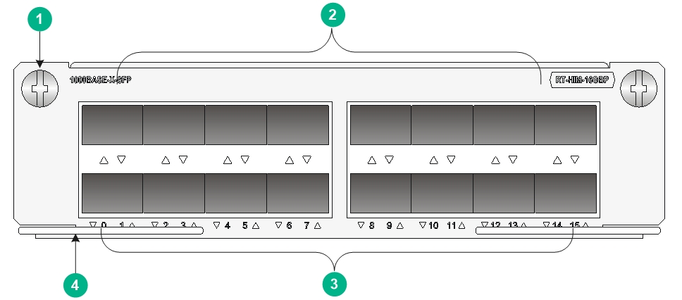
HIM-16GBP
The HIM-16GBP high-speed Layer 3 GE interface module provides 16 SFP ports. These SFP ports support Layer 3 routing.
Front panel
Figure 24 Front panel
|
(1) Captive screw |
(2) SFP ports |
|
(3) SFP port LEDs |
(4) Ejector lever |
LED
Table 33 SFP port LED description
|
Status |
Description |
|
Off |
No link is present. |
|
Steady green |
A 1000 Mbps link is present. |
|
Flashing green |
Data is being transmitted and received at 1000 Mbps. |
|
Steady yellow |
A 100 Mbps link is present. |
|
Flashing yellow |
Data is being transmitted and received at 100 Mbps. |
Interface specifications
Table 34 SFP port specifications
|
Item |
Specification |
|
Transceiver module type |
SFP |
|
Connector type |
LC |
|
Number of interfaces |
16 |
|
Interface standards |
802.3, 802.3u, 802.3ab |
|
Supported frame format |
· Ethernet_II · Ethernet_SNAP |
|
Transmission rate |
· 100/1000 Mbps · Full duplex |
The following transceiver modules are available for the HIM-16GBP interface module:
· 100 Mbps fiber SFP transceiver modules.
· 1000 Mbps fiber SFP transceiver modules.
· 1000/100 Mbps fiber SFP transceiver modules.
· 10/100/1000 Mbps copper SFP transceiver modules (10/100/1000 Mbps autosensing is supported when the HIM-16GBP interface module uses this type of transceiver module.)
Prepare the transceiver modules yourself as required.
|
|
NOTE: Use only H3C transceiver modules for the router. Transceiver modules from other vendors might be incompatible with the router. The router reports an alarm when a non-H3C transceiver module is installed. |
Interface cables
Use interface cables for the HIM-16GBP transceiver module as follows:
· Fiber SFP transceiver module—Fiber that uses an LC connector.
· Copper SFP transceiver module—Category-5 straight-through or crossover twisted pair cable when the port is operating at 10/100 Mbps and Category-6 twisted pair cable when the port is operating at 1000 Mbps.
For the appearance and connection of the interface cables, see "Connecting an Ethernet interface cable" and "Connecting an optical interface cable."
HIM-2EXP
The HIM-2EXP 10-GE interface module provides two SFP+ ports. It is half the height of a typical HIM, and occupies one slot on a FIP.
Front panel
Figure 25 Front panel

|
(1) Captive screw |
(2) Ejector lever |
|
(3) SFP+ port LED (LINK/ACT) |
(4) SFP+ port |
LEDs
Table 35 SFP+ port LED description
|
Status |
Description |
|
Off |
No link is present. |
|
Steady green |
A link is present but no data is being transmitted or received. |
|
Flashing green |
A link is present and data is being transmitted and received. |
|
Steady yellow |
The transceiver module has failed to be detected. |
Interface specifications
Table 36 SFP+ port specifications
|
Item |
Specification |
|
Transceiver module type |
SFP+ module and SFP+ DAC cable |
|
Connector type |
LC |
|
Number of interfaces |
2 |
|
Supported physical layer type |
· LAN PHY—10GBASE-R · WAN PHY—10GBASE-W |
|
Interface rate |
· LAN PHY—10.3125 Gbps · WAN PHY—9.95328 Gbps |
Interface cables
Use an SFP+ transceiver module and an optical fiber that has an LC connector, or use an SFP+ DAC cable to connect the SFP+ port on the HIM-2EXP interface module.
For the appearance and connection of the interface cables, see "Connecting an optical interface cable."
MIMs
MIM-2GBE
The MIM-2GBE is a 2-port 10/100/1000MBASE-T copper port (RJ-45) module. The MIM-2GBE is designed for router-LAN communication.
Front panel

|
(1) GE port |
(2) GE port link LED (LINK) |
|
(3) Captive screw |
(4) GE port active LED (ACT) |
LEDs
Table 37 LED description
|
LED |
Status |
Description |
|
LINK |
Off |
No link is present. |
|
On |
A link is present. |
|
|
ACT |
Off |
No data is being received or transmitted. |
|
Flashing |
Data is being received or transmitted. |
Interface specifications
Table 38 Interface specifications
|
Item |
Specification |
|
|
Connector type |
RJ-45 |
|
|
Number of interfaces |
2 |
|
|
Interface standards |
802.3, 802.3u, 802.3ab |
|
|
Interface type |
Auto MDI/MDI-X |
|
|
Supported frame format |
· Ethernet_II · Ethernet_SNAP |
|
|
Transmission distance |
100 m (328.08 ft) |
|
|
Interface speed and duplex mode |
10 Mbps |
Full/half duplex, auto-negotiation |
|
100 Mbps |
Full/half duplex, auto-negotiation |
|
|
1000 Mbps |
Full duplex |
|
|
|
NOTE: · The MDI standard is typically used on the Ethernet interface of network adapters; the MDI-X standard is typically used on hubs or LAN switches. · When 10/100 Mbps and half duplex/full duplex are specified for an Ethernet copper port, the Ethernet copper port operates in forced mode. When 1000 Mbps is specified or the interface speed and the duplex mode are not simultaneously specified for an Ethernet copper port, the port operates in auto-negotiation mode. · An Ethernet copper port supports auto MDI/MDI-X in both forced or auto-negotiation mode. |
Interface cables
A MIM-2GBE uses a category-5 straight-through or crossover Ethernet cable when operating at 10/100 Mbps and uses a category-6 cable (recommended) when operating at 1000 Mbps. For the appearance and connection of a MIM-2GBE interface cable, see "Connecting an Ethernet interface cable."
MIM-8E1(75)/MIM-8E1(75)-F
The MIM-8E1(75) is an 8-port channelized E1 interface module, which transmits, receives, and processes eight channels of E1 data, and supports CE1 access.
The MIM-8E1(75)-F is an 8-port non-channelized E1 interface module. It differs from the MIM-8E1(75) in these ways:
· The FE1 operating mode supported by the MIM-8E1(75)-F allows only one n × 64 kbps bundle to be formed on each interface, where n = 1 to 31.
· The MIM-8E1(75) allows arbitrary grouping of 31 channels and thereby multiple bundles.
Front panels
Figure 27 Front panel of MIM-8E1(75)

|
(1) DB-68 connector |
(2) Carrier signal LED (LINK/ACT) |
|
(3) Captive screw |
(4) Loopback/alarm LED (LP/AL) |
Figure 28 Front panel of MIM-8E1(75)-F

The front panel of MIM-8E1(75)-F is similar to that of MIM-8E1(75).
LEDs
|
LED |
Status |
Description |
|
LINK/ACT (Green) |
Off |
No carrier signals are being received. |
|
On |
Carrier signals are being received. |
|
|
Flashing |
Data is being transmitted or received. |
|
|
LP/AL (Yellow) |
Off |
No loopback or alarms have occurred. |
|
On |
The interface is in loopback state. |
|
|
Flashing |
A minimum of one alarm of the type of AIS, LFA, or RAI has occurred. |
Interface specifications
Table 40 Interface specifications
|
Item |
Specification |
|
Connector type |
DB-68 |
|
Number of interfaces |
1 |
|
Interface standard |
G.703 |
|
Interface speed |
2.048 Mbps |
|
Interface cable type |
75-ohm 8E1 splitter cable |
|
Cable characteristic impedance |
75 ohm |
|
Working modes |
E1, CE1, and FE1 (supported by the MIM-8E1(75)-F only) |
|
Services supported |
· Backup · Terminal access service |
Interface cables
The MIM-8E1(75) or MIM-8E1(75)-F provides eight E1 ports and uses a 75-ohm splitter cable. At one end of this 16-core coaxial cable is a DB-68 connector used to connect to the device, and at the other end are 16 BNC connectors used to connect to the peer devices.
|
|
NOTE: · The MIM-8E1(75)/MIM-8E1(75)-F does not support ISDN PRI. · For the MIM-8E1(75), if you use the timeslot binding command on the controller E1 interface, the system automatically creates a serial interface, on which the configuration takes effect. The MIM-8E1(75)-F does not have any controller E1 interfaces, and a physical interface corresponds to one and only one serial interface, which is automatically created without the need of additional configuration. · For the appearance and connection of a MIM-8E1(75)/MIM-8E1(75)-F interface cable, see "Connecting an E1 interface cable." |
MIM-8T1/MIM-8T1-F
The MIM-8T1 is an 8-port channelized T1 interface module, which transmits, receives, and processes eight channels of T1 data, and supports CT1 access.
The MIM-8T1-F is an 8-port non-channelized T1 interface module. It differs from the MIM-8T1 in these ways:
· The FT1 operating mode supported by the MIM-8T1-F allows only one n × 64 kbps OR 56 kbps bundle to be formed on each interface, where n is in the range 1 to 24.
· The MIM-8T1 allows arbitrary grouping of 24 channels and thereby multiple bundles.
Front panels
Figure 29 Front panel of MIM-8T1

|
(1) DB-68 connector |
(2) Carrier signal LED (LINK/ACT) |
|
(3) Captive screw |
(4) Loopback/Alarm LED (LP/AL) |
Figure 30 Front panel of MIM-8T1-F

The front panel of the MIM-8T1-F is similar to that of the MIM-8T1.
Interface specifications
Table 41 Interface specifications
|
Item |
Specification |
|
Connector type |
RJ-45 |
|
Number of interfaces |
1 |
|
Interface standard |
· G.703/T1 102 · G.704 · AT&T TR 54016 · AT&T TR 62411 · ANSI T1.403 |
|
Interface speed |
1.544 Mbps |
|
Interface cable type |
8T1 splitter cable |
|
Working modes |
· CT1 (supported by the MIM-8T1) · FT1 (supported by the MIM-8T1-F) |
|
Services supported |
· Backup · Terminal access service |
LEDs
|
LED |
Status |
Description |
|
LINK/ACT (Green) |
Off |
No carrier signals are being received. |
|
On |
Carrier signals are being received. |
|
|
Flashing |
Data is being transmitted or received. |
|
|
LP/AL (Yellow) |
Off |
No loopback or alarms occur. |
|
On |
The interface is in loopback state. |
|
|
Flashing |
A minimum of one alarm of the type of AIS, LFA, or RAI occurs. |
Interface cables
The MIM-8T1 or MIM-8T1-F provides eight T1 interfaces and uses an 8T1 splitter cable. At one end of this cable is a DB-68 connector used to connect to the device, and at the other end are eight RJ-45 connectors used to connect to the peer devices.
|
|
NOTE: · The MIM-8T1/MIM-8T1-F does not support ISDN PRI. · For the MIM-8T1, if you use the timeslot binding command on the controller T1 interface, the system automatically creates the corresponding serial interface, on which you can make configurations. The MIM-8T1-F does not have a controller T1 interface, and a physical interface corresponds to one and only one serial interface, which is automatically created without the need of additional configuration. · For the appearance and connection of a MIM-8T1/MIM-8T1-F interface cable, see "Connecting a T1 interface cable." |
MIM-1CE3
The MIM-1CE3 is a 1-port channelized E3 interface module. It has the following features:
· In E3 mode, it transceives and processes high-speed data streams over the E3 channel, and provides access to E3 data streams.
· In CE3 mode, it provides the low-speed access service at N × 64 kbps, where N is smaller than or equal to 128.
|
|
NOTE: · E3 represents the tertiary group rate of the E series in the TDM system, which is 34.368 Mbps. · An E3 channel can be channelized into 16 E1 channels through the demultiplex processes of E23 and E12, with each E1 channel supporting both the E1 and CE1 operating modes. E23 indicates either E2-to-E3 multiplex or E3-to-E2 demultiplex, and E12 indicates E1-to-E2 multiplex or E2-to-E1 demultiplex. E23 and E12 discussed here represent the demultiplex process. |
Front panel

|
(1) Carrier signal LED (LINK/ACT) |
(2) TX interface |
|
(3) RX interface |
(4) Captive screw |
|
(5) Loopback/Alarm LED (LP/AL) |
|
LEDs
|
LED |
Status |
Description |
|
LINK/ACT |
Off |
No carrier signals are received. |
|
On |
Carrier signals are received. |
|
|
Flashing |
Data is being transmitted or received. |
|
|
LP/AL |
Off |
No loopback or alarms occur. |
|
On |
The interface is in loopback state. |
|
|
Flashing |
A minimum of one alarm of the type of AIS, LFA, or RAI has occurred. · LFA—Loss of frame alignment. · AIS—Alarm indication signal. · RAI—Remote alarm indication. |
Interface specifications
Table 44 Interface specifications
|
Item |
Specification |
|
Connector type |
SMB |
|
Number of interfaces |
2 |
|
Interface standards |
G. 703, G.704, G.751 |
|
Interface speed |
34.368 Mbps |
|
Cable type |
75-ohm E3 coaxial cable |
|
Working modes |
E3/CE3 |
|
Services supported |
E3 leased line |
Interface cables
The MIM-1CE3 provides two SMB interfaces, with one interface acting as the transmission end (Tx) and the other as the receiving end (Rx). The Tx and Rx interfaces operate in the 75-ohm unbalanced transmission mode and thereby need a pair of 75-ohm unbalanced coaxial cables in use for connection with the peer device.
|
|
NOTE: · The MIM-1CE3 and MIM-1CT3 use the same type of E3/T3 cable. · The E3/T3 cable is an optional accessory for the MIM-1CE3 to be separately ordered if needed. · For the appearance and connection of an E3/T3 cable, see "Connecting a CE3/CT3/T3 interface cable." |
MIM-1CT3
The MIM-1CT3 is a 1-port channelized T3 interface module. It has the following features:
· In T3 mode, it transceives and processes high-speed data streams over the T3 channel, and provides access to T3 data streams.
· In CT3 mode, it provides the low-speed accessing service at N × 64 or N × 56 kbps, where N is smaller than or equal to 128.
|
|
NOTE: · T3 represents the tertiary group rate of the T series in the TDM system, which is 44.736 Mbps. · A T3 channel can be channelized into 28 T1 channels through the demultiplex processes of T23 and T12, with each T1 channel supporting both the T1 and CT1 operating modes. T23 indicates either T2-to-T3 multiplex or T3-to-T2 demultiplex, and T12 indicates T1-to-T2 multiplex or T2-to-T1 demultiplex. T23 and T12 discussed here represent the demultiplex process. |
Front panel

|
(1) Carrier signal LED (LINK/ACT) |
(2) TX interface |
|
(3) RX interface |
(4) Captive screw |
|
(5) Loopback/alarm LED (LP/AL) |
|
LEDs
|
LED |
Status |
Description |
|
LINK/ACT |
Off |
No carrier signals are being received. |
|
On |
Carrier signals are being received. |
|
|
Flashing |
Data is being transmitted or received. |
|
|
LP/AL |
Off |
No loopback or alarms occur. |
|
On |
The interface is in loopback state. |
|
|
Flashing |
A minimum of one alarm of the type of AIS, LFA, or RAI has occurred. · LFA—Loss of frame alignment. · AIS—Alarm indication signal. · RAI—Remote alarm indication. |
Interface specifications
Table 46 Interface specifications
|
Item |
Specification |
|
Connector type |
SMB |
|
Number of interfaces |
2 |
|
Interface standards |
· G.703 · G.704 · G.752 · AT&T TR 54014 · AT&T TR 62415 · ANSI T1.107 |
|
Interface speed |
44.736 Mbps |
|
Cable type |
75-ohm T3 coaxial cable |
|
Working modes |
T3/CT3 |
|
Services supported |
T3 leased line |
Interface cables
The MIM-1CT3 provides two SMB interfaces, with one interface acting as the transmission end (Tx) and the other as the receiving end (Rx). The Tx and Rx interfaces operate in the 75-ohm unbalanced transmission mode and thereby need a pair of 75-ohm unbalanced coaxial cables in use for connection with the peer device.
|
|
NOTE: · The MIM-1CT3 and MIM-1CE3 use the same type of E3/T3 cable. · The E3/T3 cable is an optional accessory for the MIM-1CE3 to be separately ordered if needed. · For the appearance and connection of an E3/T3 cable, see "Connecting a CE3/CT3/T3 interface cable." |
MIM-1T3-V2
The MIM-1T3-V2 is a 1-port non-channelized T3 interface module. It transceives and processes high-speed data streams over the T3 channel, and provides access to T3 data streams.
|
|
NOTE: T3 represents the tertiary group rate of the T series in the TDM system, which is 44.736 Mbps. |
Front panel
Figure 33 Front panel

|
(1) TX interface |
(2) RX interface |
|
(3) Captive screw |
(4) Loopback/alarm LED (LP/AL) |
|
(5) Carrier signal LED (LINK/ACT) |
|
LEDs
Table 47 LED description
|
LED |
Status |
Description |
|
LINK/ACT |
Off |
No carrier signals are being received. |
|
On |
Carrier signals are being received. |
|
|
Flashing |
Data is being transmitted or received. |
|
|
LP/AL |
Off |
No loopback or alarms occur. |
|
On |
The interface is in loopback state. |
|
|
Flashing |
A minimum of one alarm of the type of AIS, LFA, or RAI has occurred. · LFA—Loss of frame alignment. · AIS—Alarm indication signal. · RAI—Remote alarm indication. |
Interface specifications
Table 48 Interface specifications
|
Item |
Specification |
|
Connector type |
SMB |
|
Number of interfaces |
2 |
|
Interface standards |
· G.703 · G.704 · G.752 · AT&T TR 54014 · AT&T TR 62415 · ANSI T1.107 |
|
Interface speed |
44.736 Mbps |
|
Cable type |
75-ohm T3 coaxial cable |
|
Working modes |
T3 |
|
Services supported |
T3 leased line |
Interface cables
The MIM-1T3-V2 provides two SMB interfaces, with one interface acting as the transmission end (Tx) and the other as the receiving end (Rx). The Tx and Rx interfaces operate in the 75-ohm unbalanced transmission mode and thereby need a pair of 75-ohm unbalanced coaxial cables in use for connection with the peer device.
|
|
NOTE: · The MIM-1T3-V2 and MIM-1CE3 use the same type of E3/T3 cable. · The E3/T3 cable is an optional accessory for the MIM-1T3-V2 to be separately ordered if needed. · For the appearance and connection of an E3/T3 cable, see "Connecting a CE3/CT3/T3 interface cable." |
MIM-2SAE/MIM-4SAE/MIM-8SAE
The MIM-2SAE, MIM-4SAE, and MIM-8SAE are 2/4/8-port enhanced synchronous/asynchronous serial interface modules.
The MIM-2SAE/MIM-4SAE/MIM-8SAE only works in synchronous mode to receive, send and process the synchronous serial data. The MIM-2SAE/MIM-4SAE/MIM-8SAE supports the DTE/DCE mode.
Front panels
Figure 34 Front panel of MIM-2SAE

|
(1) Serial interface |
(2) Serial interface LINK LED |
|
(3) Captive screw |
(4) Serial interface ACT LED |
Figure 35 Front panel of MIM-4SAE

|
(1) Serial interface |
(2) Serial interface LINK LED |
|
(3) Captive screw |
(4) Serial interface ACT LED |
Figure 36 Front panel of MIM-8SAE

|
(1) Serial interface (7) |
(2) Serial interface 7 LINK/ACT LED |
|
(3) Captive screw |
(4) Serial interface 3 LINK/ACT LED |
|
(5) Serial interface (3) |
|
LEDs
· A LINK LED and an ACT LED are provided for each channel of the MIM-2SAE/MIM-4SAE.
· The MIM-8SAE provides only one LED for each channel.
Table 49 MIM-2SAE/MIM-4SAE LED description
|
LED |
Status |
Description |
|
LINK |
Off |
No link is present. |
|
On |
A link is present. |
|
|
ACT |
Off |
No data is being received or transmitted. |
|
Flashing |
Data is being received or transmitted. |
Table 50 MIM-8SAE LED description
|
LED status |
Description |
|
On |
A link is present. |
|
Flashing |
Data is being received or transmitted. |
Interface specifications
Table 51 Interface specifications
|
Item |
Specification (in synchronous mode) |
|
|
Connector type |
DB-28 |
|
|
Number of interfaces |
· MIM-2SAE: 2 · MIM-4SAE: 4 · MIM-8SAE: 8 |
|
|
Interface standard and working mode |
V.24 |
V.35, RS-449, X.21, RS-530 |
|
DTE, DCE |
DTE, DCE |
|
|
Minimum baud rate |
1200 bps |
1200 bps |
|
Max. baud rate |
64 Kbps |
2.048 Mbps |
|
Cable type |
· V.24 DTE cable · V.24 DCE cable · V.35 DTE cable · V.35 DCE cable · X.21 DTE cable · X.21 DCE cable · RS-449 DTE cable · RS-449 DCE cable · RS-530 DTE cable · RS-530 DCE cable |
|
|
Services supported |
DDN leased line |
|
Interface cables
Each interface on the MIM-2SAE/MIM-4SAE/MIM-8SAE is a 28-pin connector, and the interface cables for the MIM-2SAE/MIM-4SAE/MIM-8SAE are synchronous/asynchronous serial interface cables with DB-28 connectors.
Before connecting cables to the interfaces on the MIM-2SAE/MIM-4SAE/MIM-8SAE, examine the line properties. The following are cable options depending on different line properties:
· V.24 DTE cable—DB-25 (male) connector at the network end
· V.24 DCE cable—DB-25 (female) connector at the network end
· V.35 DTE cable—34-pin (male) connector at the network end
· V.35 DCE cable—34-pin (female) connector at the network end
· X.21 DTE cable—DB-15 (male) connector at the network end
· X.21 DCE cable—DB-15 (female) connector at the network end
· RS-449 DTE cable— DB-37 (male) connector at the network end
· RS-449 DCE cable—DB-37 (female) connector at the network end
· RS-530 DTE cable—DB-25 (male) connector at the network end
· RS-530 DCE cable—DB-25 (female) connector at the network end
|
|
NOTE: · The above cables are all optional for the MIM-2SAE/MIM-4SAE/MIM-8SAE to be separately ordered if needed. · All the above cables have a DB-28 connector at one end for connection with the router, and different types of connectors at the other end depending on the interface on the network side. · For the appearance and connection of a MIM-2SAE/MIM-4SAE/MIM-8SAE interface cable, see "Connecting a serial interface cable." |
MICs
MIC-GP4L
The MIC-GP4L provides four combo interfaces. Each combo interface consists of an SFP port and a RJ-45 copper port. The SFP port and the copper port cannot take effect at the same time. You can use command lines to activate the SFP port or the copper port. By default, the copper port is activated.
Front panel
Figure 37 Front panel

|
(1) Combo interfaces |
(2) Captive screw |
|
(3) Combo SFP port LINK/ACT LED |
(4) Combo copper port LINK LED |
|
(5) Combo copper port ACT LED |
|
LEDs
Table 52 LED description
|
LED |
Status |
Description |
|
SFP port LINK/ACT LED |
Steady green |
A link is present. |
|
Flashing green |
Data is being received or transmitted. |
|
|
Off |
No link is present. |
|
|
Combo copper port LINK LED |
Steady green |
A link is present. |
|
Off |
No link is present. |
|
|
Combo copper port ACT LED |
Steady orange |
Data is being received or transmitted. |
|
Off |
No data is being received or transmitted. |
Interface specifications
Table 53 Interface specifications
|
Item |
Specification |
|
Connector type |
RJ-45, SFP/LC |
|
Number of interfaces |
4 combo interfaces |
|
Interface standards |
802.3, 802.3u, 802.3ab |
|
Supported frame format |
· Ethernet_II · Ethernet_SNAP |
|
Interface speed |
· 1000BASE-X-SFP port: 1000 Mbps · 10/100/1000BASE-T copper port: 10/100/1000 Mbps |
For the transceiver modules available for the MIC-GP4L interface module, see Table 104.
Interface cables
For the appearance and connection methods of the interface cables, see "Connecting an Ethernet interface cable" and "Connecting an optical interface cable."
MIC-GP8L
The MIC-GP8L is a GE interface module. It provides eight SFP ports that support Layer 3 routing.
Front panel
Figure 38 Front panel

|
(1) 1000BASE-X-SFP ports |
(2) Captive screw |
|
(3) SFP port LINK/ACT LED |
|
LEDs
Table 54 LED description
|
LED |
Status |
Description |
|
LINK/ACT |
Flashing green |
Data is being received or transmitted. |
|
Steady green |
A link is present. |
|
|
Off |
No link is present. |
Interface specifications
Table 55 Interface specifications
|
Item |
Specification |
|
Connector type |
SFP/LC |
|
Number of interfaces |
8 |
|
Interface standards |
802.3, 802.3u, 802.3ab |
|
Supported frame format |
· Ethernet_II · Ethernet_SNAP |
|
Interface speed |
1000 Mbps |
For the transceiver modules available for the MIC-GP8L interface module, see Table 104.
Interface cables
For the appearance and connection methods of the interface cables, see "Connecting an optical interface cable."
MIC-XP4L
The MIC-XP4L is a 10-GE interface module. It provides four 10-GE SFP+ ports.
Front panel
Figure 39 Front panel

|
(1) 10GBASE-R/W-SFP+ ports |
(2) Captive screw |
|
(3) SFP+ port LINK/ACT LED |
|
LEDs
Table 56 LED description
|
LED |
Status |
Description |
|
LINK/ACT |
Flashing |
Data is being received or transmitted. |
|
Steady on |
A link is present. |
|
|
Off |
No link is present. |
Interface specifications
Table 57 Interface specifications
|
Item |
Specification |
|
Connector type |
SFP+/LC |
|
Number of interfaces |
4 |
|
Supported physical layer type |
10GBASE-R |
|
Interface speed |
10.3125 Gbps |
For the transceiver modules available for the MIC-XP4L interface module, see Table 104.
Interface cables
For the appearance and connection methods of the interface cables, see "Connecting an optical interface cable."
MIC-QP1L
The MIC-QP1L is a 40G Ethernet optical interface module and provides one QSFP+ port that can be used only for Layer 3 services.
Front panel
Figure 40 Front panel

|
(1) 40GBASE-R-QSFP+ port |
(2) QSFP+ port LINK/ACT LED |
|
(3) Captive screw |
|
LEDs
Table 58 LED description
|
LED |
Status |
Description |
|
LINK/ACT |
On |
A link is present and data is being received or transmitted. |
|
Off |
No link is present. |
Interface specifications
Table 59 Interface specifications
|
Item |
Specification |
|
Connector type |
· QSFP+/LC · QSFP+/MPO |
|
Number of interfaces |
1 |
|
Supported physical layer type |
40GBASE-R |
|
Interface speed |
40 Gbps |
For the transceiver modules available for the MIC-QP1L interface module, see Table 104.
Interface cables
For the appearance and connection methods of the interface cables, see "Connecting an optical interface cable."
MIC-SP4L
|
|
CAUTION: Only port 1 can be configured as an OC-12c/STM-4c POS/ATM port. |
The MIC-SP4L provides four fiber ports. You can use command lines to configure port 1 as an OC-3c/STM-1c or OC-12c/STM-4c POS/ATM port, and configure the other ports as OC-3c/STM-1c POS or ATM ports. By default, all fiber ports are OC-3c/STM-1c POS ports.
Front panel
Figure 41 Front panel

|
(1) OC-3c/STM-1c POS/ATM or OC-12c/STM-4c POS/ATM fiber ports |
(2) Captive screw |
|
(3) Port ACT/ALM LED |
|
LEDs
Table 60 LED description
|
LED |
Status |
Description |
|
ACT/ALM |
Flashing green |
The port is in up state and data is being received or transmitted. |
|
Steady green |
The port is in up state but no data is being received or transmitted. |
|
|
Steady red |
An alarm has occurred. |
|
|
Off |
The port is in down state. |
Interface specifications
Table 61 Interface specifications
|
Item |
Specification |
|
Connector type |
SFP/LC |
|
Number of interfaces |
4 |
|
Interface standards |
SONET OC-3c/SDH STM-1, SONET OC-12c/SDH STM-4 |
|
Interface speed |
· SONET OC-3c/SDH STM-1: 155.52 Mbps · SONET OC-12c/SDH STM-4: 622.08 Mbps |
For the transceiver modules available for the MIC-SP4L interface module, see Table 104.
Interface cables
For the appearance and connection methods of the interface cables, see "Connecting an optical interface cable."
MIC-SP8L
The MIC-SP8L provides eight Packet over SONET/SDH (POS) ports for packet transmission over SONET/SDH.
Front panel
Figure 42 Front panel

|
(1) OC-3c/STM-1c POS fiber ports |
(2) Captive screw |
|
(3) Port ACT/ALM LED |
|
LEDs
Table 62 LED description
|
LED |
Status |
Description |
|
ACT/ALM |
Flashing green |
The port is in up state and data is being received or transmitted. |
|
Steady green |
The port is in up state but no data is being received or transmitted. |
|
|
Steady red |
An alarm has occurred. |
|
|
Off |
The port is in down state. |
Interface specifications
Table 63 Interface specifications
|
Item |
Specification |
|
Connector type |
SFP/LC |
|
Number of interfaces |
8 |
|
Interface standards |
SONET OC-3c/SDH STM-1 |
|
Interface speed |
155.52 Mbps |
For the transceiver modules available for the MIC-SP8L interface module, see Table 104.
Interface cables
For the appearance and connection methods of the interface cables, see "Connecting an optical interface cable."
MIC-Xs
MIC-X-GP4GT4
A MIC-X-GP4GT4 GE interface module provides four 1000BASE-X-SFP ports and four 10/100/1000BASE-T ports.
Front panel
Figure 43 Front panel

|
(1) Captive screw |
(2) 1000BASE-X-SFP ports |
|
(3) 10/100/1000BASE-T port LED |
(4) 10/100/1000BASE-T ports |
|
(5) 1000BASE-X-SFP port LED |
|
LEDs
Table 64 LED description
|
LED |
Status |
Description |
|
1000BASE-X-SFP port LED |
Off |
The port is not connected or the port is faulty. |
|
Steady green |
A 1000 Mbps link is present on the port. |
|
|
Flashing green (8 Hz) |
The port is sending and receiving data at 1000 Mbps. |
|
|
Steady yellow |
A 100 Mbps link is present on the port. |
|
|
Flashing yellow (8 Hz) |
The port is sending and receiving data at 100 Mbps. |
|
|
10/100/1000BASE-T port LED |
Off |
The port is not connected or the port is faulty. |
|
Steady green |
A 1000 Mbps link is present on the port. |
|
|
Flashing green (8 Hz) |
The port is sending and receiving data at 1000 Mbps. |
|
|
Steady yellow |
A 100 Mbps link is present on the port. |
|
|
Flashing yellow (8 Hz) |
The port is sending and receiving data at 100 Mbps. |
Interface specifications
Table 65 Interface specifications
|
Item |
Specification |
|
Connector type |
· 1000BASE-X-SFP port: SFP/LC · 1000BASE-T port: RJ-45 |
|
Number of interfaces |
8 |
|
Interface standards |
802.3, 802.3u, 802.3ab |
|
Frame format |
· Ethernet_II · Ethernet_SNAP |
|
Interface speed |
· 1000BASE-X-SFP port: 100/1000 Mbps · 1000BASE-T port: 100/1000 Mbps |
For the transceiver modules available for a MIC-X-GP4GT4 interface module, see Table 104.
Interface cables
For the appearance and connection methods of the interface cables, see "Connecting an Ethernet interface cable" and "Connecting an optical interface cable."
MIC-X-GP8
A MIC-X-GP8 GE interface module provides eight 1000BASE-X-SFP ports.
Front panel
Figure 44 Front panel

|
(1) Captive screw |
(2) 1000BASE-X-SFP ports |
|
(3) 1000BASE-X-SFP port LED |
|
LEDs
Table 66 LED description
|
LED |
Status |
Description |
|
1000BASE-X-SFP port LED |
Off |
The port is not connected or the port is faulty. |
|
Steady green |
A 1000 Mbps link is present on the port. |
|
|
Flashing green (8 Hz) |
The port is sending and receiving data at 1000 Mbps. |
|
|
Steady yellow |
A 100 Mbps link is present on the port. |
|
|
Flashing yellow (8 Hz) |
The port is sending and receiving data at 100 Mbps. |
Interface specifications
Table 67 Interface specifications
|
Item |
Specification |
|
Connector type |
SFP/LC |
|
Number of interfaces |
8 |
|
Interface standards |
802.3, 802.3u, 802.3ab |
|
Frame format |
· Ethernet_II · Ethernet_SNAP |
|
Interface speed |
100/1000 Mbps |
For the transceiver modules available for a MIC-X-GP8 interface module, see Table 104.
Interface cables
For the appearance and connection methods of the interface cables, see "Connecting an optical interface cable."
MIC-X-GP10
A MIC-X-GP10 GE interface module provides ten 1000BASE-X-SFP ports.
Front panel
Figure 45 Front panel

|
(1) Captive screw |
(2) 1000BASE-X-SFP ports |
|
(3) 1000BASE-X-SFP port LED |
|
LEDs
Table 68 LED description
|
LED |
Status |
Description |
|
1000BASE-X-SFP port LED |
Off |
The port is not connected or the port is faulty. |
|
Steady green |
A 1000 Mbps link is present on the port. |
|
|
Flashing green (8 Hz) |
The port is sending and receiving data at 1000 Mbps. |
|
|
Steady yellow |
A 100 Mbps link is present on the port. |
|
|
Flashing yellow (8 Hz) |
The port is sending and receiving data at 100 Mbps. |
Interface specifications
Table 69 Interface specifications
|
Item |
Specification |
|
Connector type |
SFP/LC |
|
Number of interfaces |
10 |
|
Interface standards |
802.3, 802.3u, 802.3ab |
|
Frame format |
· Ethernet_II · Ethernet_SNAP |
|
Interface speed |
100/1000 Mbps |
For the transceiver modules available for a MIC-X-GP10 interface module, see Table 104.
Interface cables
For the appearance and connection methods of the interface cables, see "Connecting an optical interface cable."
MIC-X-XP2
A MIC-X-XP2 is a 10-GE interface module. It provides two 10-GE SFP+ ports.
Front panel
Figure 46 Front panel

|
(1) Captive screw |
(2) 10GBASE-R-SFP+ ports |
|
(3) SFP+ port LED (LINK/ACT) |
|
LEDs
Table 70 LED description
|
LED |
Status |
Description |
|
LINK/ACT |
Flashing |
Data is being received or transmitted. |
|
Steady on |
A link is present. |
|
|
Off |
No link is present. |
Interface specifications
Table 71 Interface specifications
|
Item |
Specification |
|
Connector type |
SFP+/LC |
|
Number of interfaces |
2 |
|
Supported physical layer type |
10GBASE-R |
|
Interface speed |
10.3125 Gbps |
For the transceiver modules available for a MIC-X-XP2 interface module, see Table 104.
Interface cables
For the appearance and connection methods of the interface cables, see "Connecting an optical interface cable."
MIC-X-XP4
A MIC-X-XP4 is a 10-GE interface module. It provides four 10-GE SFP+ ports.
Front panel
Figure 47 Front panel

|
(1) Captive screw |
(2) 10GBASE-R-SFP+ ports |
|
(3) SFP+ port LED (LINK/ACT) |
|
LEDs
Table 72 LED description
|
LED |
Status |
Description |
|
LINK/ACT |
Flashing |
Data is being received or transmitted. |
|
Steady on |
A link is present. |
|
|
Off |
No link is present. |
Interface specifications
Table 73 Interface specifications
|
Item |
Specification |
|
Connector type |
SFP+/LC |
|
Number of interfaces |
4 |
|
Supported physical layer type |
10GBASE-R |
|
Interface speed |
10.3125 Gbps |
For the transceiver modules available for a MIC-X-XP4 interface module, see Table 104.
Interface cables
For the appearance and connection methods of the interface cables, see "Connecting an optical interface cable."
MIC-X-XP4W
A MIC-X-XP4W is a 10-GE interface module. It provides four 10-GE SFP+ ports and supports switchover between LAN/WAN modes.
Front panel
Figure 48 Front panel

|
(1) Captive screw |
(2) 10GBASE-R/W-SFP+ ports |
|
(3) SFP+ port LED (LINK/ACT) |
|
LEDs
Table 74 LED description
|
LED |
Status |
Description |
|
LINK/ACT |
Flashing |
Data is being received or transmitted. |
|
Steady on |
A link is present. |
|
|
Off |
No link is present. |
Interface specifications
Table 75 Interface specifications
|
Item |
Specification |
|
Connector type |
SFP+/LC |
|
Number of interfaces |
4 |
|
Supported physical layer type |
10GBASE-R |
|
Interface speed |
10.3125 Gbps |
For the transceiver modules available for a MIC-X-XP4W interface module, see Table 104.
Interface cables
For the appearance and connection methods of the interface cables, see "Connecting an optical interface cable."
MIC-X-GT8
A MIC-X-GT8 GE copper interface module provides eight 10/100/1000BASE-T ports.
Front panel
Figure 49 Front panel

|
(1) Captive screw |
(2) 10/100/1000BASE-T port LED |
|
(3) 10/100/1000BASE-T ports |
|
LEDs
Table 76 LED description
|
LED |
Status |
Description |
|
10/100/1000BASE-T port LED |
Off |
The port is not connected or the port is faulty. |
|
Steady green |
A 1000 Mbps link is present on the port. |
|
|
Flashing green (8 Hz) |
The port is sending and receiving data at 1000 Mbps. |
|
|
Steady yellow |
A 100 Mbps link is present on the port. |
|
|
Flashing yellow (8 Hz) |
The port is sending and receiving data at 100 Mbps. |
Interface specifications
Table 77 Interface specifications
|
Item |
Specification |
|
Connector type |
RJ-45 |
|
Number of interfaces |
8 |
|
Interface standards |
802.3, 802.3u, 802.3ab |
|
Interface type |
MDI/MDIX autosensing |
|
Frame format |
· Ethernet_II · Ethernet_SNAP |
|
Interface speed |
100/1000 Mbps autosensing, full-duplex, auto-negotiation |
Interface cables
For the appearance and connection methods of the interface cables, see "Connecting an Ethernet interface cable."
MIC-X-CLP2
A MIC-X-CLP2 interface module provides two OC-3c/STM-1 CPOS interfaces.
Front panel
Figure 50 Front panel

|
(1) Captive screw |
(2) SFP port |
|
(3) SFP port LED (ACT/ALM) |
|
LEDs
Table 78 LED description
|
LED |
Status |
Description |
|
SFP port LED (ACT/ALM) |
Flashing green |
The interface is up and is sending or receiving data correctly. |
|
Steady green |
The interface is up and is not sending or receiving data. |
|
|
Steady red |
A transceiver module has been installed in the port, but the port is down. |
|
|
Off |
No transceiver module has been installed in the port. |
Interface specifications
Table 79 Interface specifications
|
Item |
Specification |
|
Connector type |
SFP/LC |
|
Number of interfaces |
2 |
|
Interface standards |
SONET OC-3/SDH STM-1 |
|
Interface speed |
155.52 Mbps |
For the transceiver modules available for a MIC-X-CLP2 interface module, see Table 104.
Interface cables
For the appearance and connection methods of the interface cables, see "Connecting an optical interface cable."
MIC-X-CLP4
A MIC-X-CLP4 interface module provides four OC-3c/STM-1 CPOS interfaces.
Front panel
Figure 51 Front panel

|
(1) Captive screw |
(2) SFP port |
|
(3) SFP port LED (ACT/ALM) |
|
LEDs
Table 80 LED description
|
LED |
Status |
Description |
|
SFP port LED (ACT/ALM) |
Flashing green |
The interface is up and is sending or receiving data correctly. |
|
Steady green |
The interface is up and is not sending or receiving data. |
|
|
Steady red |
A transceiver module has been installed in the port, but the port is down. |
|
|
Off |
No transceiver module has been installed in the port. |
Interface specifications
Table 81 Interface specifications
|
Item |
Specification |
|
Connector type |
SFP/LC |
|
Number of interfaces |
4 |
|
Interface standards |
SONET OC-3/SDH STM-1 |
|
Interface speed |
155.52 Mbps |
For the transceiver modules available for a MIC-X-CLP4 interface module, see Table 104.
Interface cables
For the appearance and connection methods of the interface cables, see "Connecting an optical interface cable."
MIC-X-SP4
A MIC-X-SP4 interface module provides four fiber ports. You can use the card-mode command to configure the four fiber ports as OC-3c/STM-1c or OC-12c/STM-4c POS interfaces. By default, the ports are OC-3c/STM-1c POS interfaces.
|
|
IMPORTANT: If you configure all ports on a MIC-X-SP4 interface module as OC-12c/STM-4c POS interfaces, only interface 0 works. The other three interfaces do not work. |
Front panel
Figure 52 Front panel

|
(1) Captive screw |
(2) SFP ports |
|
(3) SFP port LED (ACT/ALM) |
|
LEDs
Table 82 LED description
|
LED |
Status |
Description |
|
SFP port LED (ACT/ALM) |
Flashing green |
The interface is up and is sending or receiving data correctly. |
|
Steady green |
The interface is up and is not sending or receiving data. |
|
|
Steady red |
A transceiver module has been installed in the port, but the port is down. |
|
|
Off |
No transceiver module has been installed in the port. |
Interface specifications
Table 83 Interface specifications
|
Item |
Specification |
|
Connector type |
SFP/LC |
|
Number of interfaces |
4 |
|
Interface standards |
SONET OC-3c/SDH STM-1 SONET OC-12c/SDH STM-4 |
|
Interface speed |
155.52 Mbps 622.08 Mbps |
For the transceiver modules available for a MIC-X-SP4 interface module, see Table 104.
Interface cables
For the appearance and connection methods of the interface cables, see "Connecting an optical interface cable."
MIC-X-SP8
A MIC-X-SP8 interface module provides eight OC-3c/STM-1c POS interfaces.
Front panel
Figure 53 Front panel

|
(1) Captive screw |
(2) SFP ports |
|
(3) SFP port LED (ACT/ALM) |
|
LEDs
Table 84 LED description
|
LED |
Status |
Description |
|
SFP port LED (ACT/ALM) |
Flashing green |
The interface is up and is sending or receiving data correctly. |
|
Steady green |
The interface is up and is not sending or receiving data. |
|
|
Steady red |
A transceiver module has been installed in the port, but the port is down. |
|
|
Off |
No transceiver module has been installed in the port. |
Interface specifications
Table 85 Interface specifications
|
Item |
Specification |
|
Connector type |
SFP/LC |
|
Number of interfaces |
8 |
|
Interface standards |
SONET OC-3c/SDH STM-1 |
|
Interface speed |
155.52 Mbps |
For the transceiver modules available for a MIC-X-SP8 interface module, see Table 104.
Interface cables
For the appearance and connection methods of the interface cables, see "Connecting an optical interface cable."
MIC-X-ET16
A MIC-X-ET16 interface module provides 16 E1 interfaces, which can operate in channelized or unchannelized mode. In unchannelized mode, each E1 interface provides 2.048 Mbps of data bandwidth. In channelized mode, each E1 interface is divided into 32 timeslots (each timeslot has a rate of 64 Kbps). Each timeslot can be used as a logical interface and supports bundling.
Front panel
Figure 54 Front panel

|
(1) Captive screw |
(2) E1 interfaces (16 in total) |
|
(3) E1-HM96 interface LED (ACT/ALM) |
|
LEDs
Table 86 LED description
|
LED |
Status |
Description |
|
E1-HM96 interface LED (ACT/ALM) |
Flashing green |
The interface is sending or receiving data correctly. |
|
Steady green |
The interface is up and is not sending or receiving data. |
|
|
Steady red |
An alarm has occurred. |
Interface specifications
Table 87 Interface specifications
|
Item |
Specification |
|
Connector type |
HM96 |
|
Number of interfaces |
16 |
|
Interface type |
E1 |
|
Interface rate |
2.048 Mbps |
|
Cable type |
BNC 75-ohm E1 cable, 3.0m, (HD96 female), SYFVZP-75-1-1 grey, 32*BNCSM |
|
Cable characteristic impedance |
75 ohm |
Interface cables
Use 75-ohm 16E1 splitter cables to connect the E1 ports on the interface module. For the appearance and connection methods of the interface cables, see "Connecting an E1 interface cable."
MIC-X-CNDE-SJK
|
|
CAUTION: · Do not run services or remove an MIC-X-CNDE-SJK interface module when the module is starting up. Wait until the RUN LED is steady green or is flashing green for 30 seconds. · Before removing an MIC-X-CNDE-SJK interface module during device operation, press and hold the REMOVE button on the module until the RUN LED is off. |
A MIC-X-CNDE-SJK interface module is a State Cryptography Administration (SCA) SM encryption module. It supports SM1, SM2, and SM4 encryption algorithms and provides high performance and reliable data encryption features for routers.
Front panel
Figure 55 Front panel

|
(1) Captive screw |
(2) REMOVE button |
|
(3) RUN LED |
|
LEDs
Table 88 LED description
|
LED |
Status |
Description |
|
RUN |
Flashing yellow |
· The module is initializing. · The REMOVE button is pressed, and the module is releasing the resources. |
|
Flashing green |
The module is operating correctly and data is being received or transmitted. |
|
|
Steady green |
The module is operating correctly but no data is being received or transmitted. |
|
|
Off |
· The resources have been released and you can remove the module. · The module is faulty. |
MIC-X-Adapter
Some MIC interface modules can be assembled into MIC-X interface modules by using a MIC-X-Adapter.
For the procedure of assembling a MIC interface module into a MIC-X interface module by using a MIC-X-Adapter, see the router installation guide.
Connecting interface cables
Connecting an Ethernet interface cable
Appearance of an Ethernet cable
![]()
10/100 Mbps Ethernet uses category-5 twisted pair cables, while 1000 Mbps Ethernet uses category-5 enhanced or category-6 twisted pair cables. Twisted pair cables include straight-through cables and crossover cables.
Category-5 cables provide a transmission frequency of 100 MHz for voice and data transmission; they are mainly used in 100BASE-T and 10BASE-T networks. Category-5 cables are common Ethernet cables, which can also be used to transmit 1000 Mbps Ethernet data.
Category-5 enhanced cables feature low attenuation and crosstalk, providing higher attenuation to crosstalk ratio (ACR), less delay error and higher performance than category-5 cables. Category-5 enhanced cables are mainly used in 1000 Mbps Ethernet networks.
Category-6 cables provide a transmission frequency of 1 MHz to 250 MHz, and improve the performance on crosstalk and return loss. A fine better return loss performance is extremely important for new-generation full-duplex high-speed networks. Category-6 cables have sufficient power sum ACR (PS-ACR) when working at 200 MHz. They provide a bandwidth two times than that of category-5 enhanced cables, thus featuring a higher transmission performance. Therefore, category-6 cables are suitable for applications requiring a transmission speed of more than 1 Gbps.
The 10/100 Mbps Ethernet uses two pairs of cables, orange/white, orange, green/white and green cables, to transmit and receive data, while the 1000 Mbps Ethernet uses four pairs of cables to transmit and receive data.
For the pinouts of common twisted pair cables, see the following tables. (A and B represent the two ends of a cable.)
Table 89 Straight-through cable pinouts
|
Pinout No. |
A |
B |
|
1 |
Orange/white |
Orange/white |
|
2 |
Orange |
Orange |
|
3 |
Green/white |
Green/white |
|
4 |
Blue |
Blue |
|
5 |
Blue/white |
Blue/white |
|
6 |
Green |
Green |
|
7 |
Brown/white |
Brown/white |
|
8 |
Brown |
Brown |
Table 90 Crossover cable pinouts
|
Pinout No. |
A |
B |
|
1 |
Orange/white |
Green/white |
|
2 |
Orange |
Green |
|
3 |
Green/white |
Orange/white |
|
4 |
Blue |
Blue |
|
5 |
Blue/white |
Blue/white |
|
6 |
Green |
Orange |
|
7 |
Brown/white |
Brown/white |
|
8 |
Brown |
Brown |
|
|
NOTE: Strictly follow the pinouts in the above tables when identifying or making the two types of Ethernet cables; otherwise, the communication quality might be affected. |
Connecting an Ethernet cable
1. Connect one end of an Ethernet cable to an Ethernet port on the module and the other end to the Ethernet port on the peer device. Because the Ethernet port of the module supports MDI/MDIX auto-sensing, you can use a straight-through cable or crossover cable to connect the port.
2. Examine the status of the LED of the Ethernet port after power-on. For the status of the LED, see the relevant part in this manual.
Connecting an optical interface cable
Appearance of transceiver module, optical fiber and connector
Optical interfaces need to work with SFP, SFP+, XFP, or QSFP+ transceiver modules and optical fibers with LC-type or MPO-type connectors.
Figure 57 SFP transceiver module

Figure 58 SFP+ transceiver module

Figure 59 XFP transceiver module

Figure 60 QSFP+ transceiver module (LC)

Figure 61 QSFP+ transceiver module (MPO)

Figure 62 LC-type optical fiber connector

|
(1) LC-type optical fiber connector |
(2) Optical fiber |
Figure 63 MPO connector

Connecting an optical fiber
|
|
WARNING! Never stare into an open transceiver module port, because invisible rays might be emitted from the port. |
|
|
CAUTION: Attach the dust plug to a transceiver module port if no optical fiber connector is connected to it. |
To connect an optical fiber:
1. Wear an ESD wrist strap and make sure the wrist strap is reliably grounded.
2. Remove the dust plug from the target fiber port.
Some interface modules are shipped with dust plugs as accessories. Attach the dust plugs to the empty fiber ports on the interface modules timely.
3. Pull the bail latch on the transceiver module upwards.
4. Take the transceiver module by its two sides and align it with the fiber port.
5. Push the transceiver module gently into the port until it is firmly seated in the fiber port.
6. Remove the dust plug and dust cap from the transceiver module and fiber connector, respectively. Then clean the fiber end.
7. Connect the optical fiber to the transceiver module.
¡ LC connector—Identify the Rx and Tx ports on the transceiver module and connect the LC connectors of the optical fiber to the Rx and Tx ports. Then connect the other end of the optical fiber to the peer ends. Make sure the Rx and Tx ports on the transceiver module are connected to the Tx and Rx ports at the peer end, respectively.
¡ MPO connector—Orient the connector with the white spot on it facing right. Insert the MPO fiber connector horizontally into the transceiver module. Push the MPO fiber connector into the transceiver module slightly until it clicks into place.
8. Use cable ties at a spacing of 150 mm (5.91 in) to bind optical fibers.
9. Label optical fibers according to the cable labeling specifications.
Connecting an E1 interface cable
Appearance of E1 cables, coaxial connector, and impedance converter

Figure 65 16E1 splitter cable

Figure 66 75-ohm E1 adapter cable

Figure 67 Coaxial connector

Figure 68 Impedance converter

Connecting the cable
When connecting the interface cable, pay attention to the mark on the interface to avoid wrong insertion, which might damage the interface module or even the host.
As a best practice, install a special lightning arrester at the input end of its connection cable to obtain better lightning protection when the cable is led outdoors. For more information about lightning arrestor, see the installation guide.
The connection procedure is similar for 8E1 and 16E1 splitter cables. The following procedure uses an 8E1 splitter cable as an example.
To connect an 8E1 splitter cable:
1. Plug the DB-68 end of the 75-ohm 8E1 splitter cable to the DB-68 interface of the interface module and then fasten the screws.
2. Examine the sequence number on the BNC connector and Tx/Rx mark on the other end of the cable.
¡ If the 75-ohm 8E1 splitter cable need not be extended, you can connect the BNC connector of the cable to the peer device directly.
Figure 69 Connecting the 8E1 splitter cable (1)

¡ If the 75-ohm 8E1 splitter cable need be extended, you can connect the BNC connector of the cable to the coaxial cable connector and connect the other end of the coaxial cable connector to the peer device through a 75-ohm E1 trunk cable.
Figure 70 Connecting the 8E1 splitter cable (2)

¡ If the impedance of the E1 port on the peer device is 120 ohms, you must use an impedance converter to adapt the impedance.
Connect the TX connector and the RX connector of the cable to the RX connector and the TX connector on the impedance converter, respectively. Use a network cable to connect the other end of the impedance converter to the peer device.
Figure 71 Connecting the 8E1 splitter cable (3)

3. Examine the LINK LED after connection.
¡ If the LED is on, the optical fiber link is present.
¡ If the LED is off, a fault has occurred on the link and the signal is out of synchronization. In this case, examine the link.
|
|
NOTE: · The Tx end of the cable must be connected to the Rx end of the peer device, and the Rx end of the cable to the Tx end of the peer device. · The coaxial cable connector and 75-ohm E1 trunk cable are optional accessories to be separately ordered if needed. |
Connecting a T1 interface cable
Appearance of the 8T1 splitter cable

|
|
NOTE: · When connecting the interface cable, pay attention to the mark on the interface to avoid wrong insertion, which might damage the interface module or even the host. · As a best practice, install a special lightning arrester at the input end of its connection cable to obtain better lightning protection when the cable is led outdoors. For more information about lightning arrestor, see the installation guide. |
Connecting the cable
1. Plug the DB-68 end of the 8T1 splitter cable to the DB-68 interface of the MIM-8T1/MIM-8T1-F.
2. Plug the RJ-45 end of the 8T1 splitter cable to the peer device.
3. Examine the LINK LED on the MIM-8T1/MIM-8T1-F after connection. If the LED is off, a fault has occurred on the link. In this case, examine the link.
Connecting a CE3/CT3/T3 interface cable
Appearance of the E3/T3 cable

|
|
NOTE: As a best practice, install a special lightning arrester at the input end of its connection cable to obtain better lightning protection when the cable is led outdoors. For more information about lightning arrestor, see the installation guide. |
Connecting the cable
1. Connect the SMB connector of an E3/T3 cable to the Tx port on the interface module and another end to the Rx port on the device to be connected.
2. Connect the SMB connector of another E3/T3 cable to the Rx port of interface module and another end to the Tx port on the device to be connected.
3. Examine the LINK LED on the module panel. It is off when fault has occurred on the link and signal is out of synchronization. In this case, examine the link.
Connecting a serial interface cable
Appearance of the serial interface cable

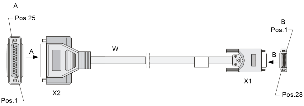


Connecting the cable
|
|
CAUTION: · Never stare into an open fiber Ethernet port, because invisible rays might be emitted from the port. · Cover the dust cover if no optical fiber connector is connected to the fiber Ethernet port. |
To connect the interface cable:
1. Examine port type of the peer device and choose the synchronous serial interface cable of correct type.
2. Plug the DB-28 end of the synchronous serial interface cable into the DB-28 interface of the SAE interface module.
3. If the WAN uses DDN line, connect the cable to the port of CSU/DSU.
4. Examine the LINK LED on the SAE panel.
¡ If the LED is on, a link is present.
¡ If the LED is off, a fault has occurred on the link and signal is out of synchronization. In this case, examine the link.
Interface module technical specifications
Table 91 Power consumption, weight, and dimensions of the interface modules
|
Module |
Min. power consumption |
Max. power consumption |
Net weight |
Width |
Depth |
Height |
|
HIM-8FE |
8.64 W |
18.29 W |
0.4 kg (0.88 lb) |
150 mm (5.9 in) |
172 mm (6.77 in) |
40 mm (1.57 in) |
|
HIM-4GBE |
7.30 W |
15.50 W |
0.35 kg (0.77 lb) |
150 mm (5.9 in) |
172 mm (6.77 in) |
40 mm (1.57 in) |
|
8.64 W |
18.29 W |
0.4 kg (0.88 lb) |
150 mm (5.9 in) |
172 mm (6.77 in) |
40 mm (1.57 in) |
|
|
HIM-4GBP |
7.21 W |
16.80 W |
0.35 kg (0.77 lb) |
150 mm (5.9 in) |
172 mm (6.77 in) |
40 mm (1.57 in) |
|
HIM-8GBP |
7.84 W |
8.80 W |
0.38 kg (0.84 lb) |
150 mm (5.9 in) |
172 mm (6.77 in) |
40 mm (1.57 in) |
|
HIM-1EXP |
8.96 W |
12.59 W |
0.36 kg (0.79 lb) |
150 mm (5.9 in) |
172 mm (6.77 in) |
40 mm (1.57 in) |
|
HIM-CL1P |
11.52 W |
13.37 W |
0.38 kg (0.84 lb) |
150 mm (5.9 in) |
172 mm (6.77 in) |
40 mm (1.57 in) |
|
HIM-CL2P |
12.48 W |
14.40 W |
0.42 kg (0.93 lb) |
150 mm (5.9 in) |
172 mm (6.77 in) |
40 mm (1.57 in) |
|
HIM-CLS1P |
8.40 W |
9.80 W |
0.38 kg (0.84 lb) |
150 mm (5.9 in) |
172 mm (6.77 in) |
40 mm (1.57 in) |
|
HIM-CLS2P |
9.34 W |
10.78 W |
0.4 kg (0.88 lb) |
150 mm (5.9 in) |
172 mm (6.77 in) |
40 mm (1.57 in) |
|
HIM-MSP2P |
3.92 W |
10.26 W |
0.35 kg (0.77 lb) |
150 mm (5.9 in) |
172 mm (6.77 in) |
40 mm (1.57 in) |
|
HIM-MSP4P |
4.58 W |
11.16 W |
0.35 kg (0.77 lb) |
150 mm (5.9 in) |
172 mm (6.77 in) |
40 mm (1.57 in) |
|
HIM-PS1P |
4.58 W |
11.16 W |
0.35 kg (0.77 lb) |
150 mm (5.9 in) |
172 mm (6.77 in) |
40 mm (1.57 in) |
|
HIM-RS2P |
14.19 W |
17.03 W |
0.5 kg (1.10 lb) |
150 mm (5.9 in) |
172 mm (6.77 in) |
40 mm (1.57 in) |
|
HIM-TS8P |
19.20 W |
20.16 W |
0.45 kg (0.99 lb) |
150 mm (5.9 in) |
172 mm (6.77 in) |
19.8 mm (0.78 in) |
|
HIM-16GBP |
18.20 W |
20.70 W |
0.55 kg (1.21 lb) |
150 mm (5.9 in) |
172 mm (6.77 in) |
40 mm (1.57 in) |
|
11.40 W |
14.20 W |
0.4 kg (0.88 lb) |
150 mm (5.9 in) |
172 mm (6.77 in) |
19.8 mm (0.78 in) |
|
|
HIM-AL1P |
9.9 W |
12.9 W |
0.4 kg (0.88 lb) |
150 mm (5.9 in) |
172 mm (6.77 in) |
40 mm (1.57 in) |
|
HIM-AL2P |
10.9 W |
13.87 W |
0.43 kg (0.95 lb) |
150 mm (5.9 in) |
172 mm (6.77 in) |
40 mm (1.57 in) |
|
HIM-4G4P |
19.2 W |
20.16 W |
0.45 kg (0.99 lb) |
150 mm (5.9 in) |
172 mm (6.77 in) |
19.8 mm (0.78 in) |
|
HIM-8GBP-V2 |
6.61 W |
13.44 W |
0.45 kg (0.99 lb) |
150 mm (5.9 in) |
172 mm (6.77 in) |
19.8 mm (0.78 in) |
|
HIM-8GBP-V3 |
22.78 W |
24.50 W |
0.45 kg (0.99 lb) |
150 mm (5.9 in) |
172 mm (6.77 in) |
19.8 mm (0.78 in) |
|
HIM-4GBP-V3 |
16.61 W |
18.20 W |
0.4 kg (0.88 lb) |
150 mm (5.9 in) |
172 mm (6.77 in) |
19.8 mm (0.78 in) |
|
HIM-8GBE-V3 |
16.43 W |
18.50 W |
0.45 kg (0.99 lb) |
150 mm (5.9 in) |
172 mm (6.77 in) |
19.8 mm (0.78 in) |
|
HIM-4GBE-V3 |
16.41 W |
18.20 W |
0.4 kg (0.88 lb) |
150 mm (5.9 in) |
172 mm (6.77 in) |
19.8 mm (0.78 in) |
|
1.14 W |
4.91 W |
0.15 kg (0.33 lb) |
150 mm (5.9 in) |
172 mm (6.77 in) |
19.8 mm (0.78 in) |
|
|
1.71 W |
2.12 W |
0.25 kg (0.55 lb) |
150 mm (5.9 in) |
172 mm (6.77 in) |
19.8 mm (0.78 in) |
|
|
MIM-8E1(75)-F |
1.71 W |
2.12 W |
0.25 kg (0.55 lb) |
150 mm (5.9 in) |
172 mm (6.77 in) |
19.8 mm (0.78 in) |
|
1.50 W |
1.67 W |
0.25 kg (0.55 lb) |
150 mm (5.9 in) |
172 mm (6.77 in) |
19.8 mm (0.78 in) |
|
|
MIM-8T1-F |
1.50 W |
1.67 W |
0.25 kg (0.55 lb) |
150 mm (5.9 in) |
172 mm (6.77 in) |
19.8 mm (0.78 in) |
|
3.10 W |
3.17 W |
0.2 kg (0.44 lb) |
150 mm (5.9 in) |
172 mm (6.77 in) |
19.8 mm (0.78 in) |
|
|
MIM-1CT3 |
4.39 W |
4.48 W |
0.2 kg (0.44 lb) |
150 mm (5.9 in) |
172 mm (6.77 in) |
19.8 mm (0.78 in) |
|
MIM-1T3-V2 |
1.14 W |
1.38 W |
0.4 kg (0.88 lb) |
150 mm (5.9 in) |
172 mm (6.77 in) |
19.8 mm (0.78 in) |
|
MIM-2SAE |
4.01 W |
4.50 W |
0.23 kg (0.51 lb) |
150 mm (5.9 in) |
172 mm (6.77 in) |
19.8 mm (0.78 in) |
|
MIM-4SAE |
4.08 W |
4.80 W |
0.24 kg (0.53 lb) |
150 mm (5.9 in) |
172 mm (6.77 in) |
19.8 mm (0.78 in) |
|
MIM-8SAE |
4.08 W |
4.18 W |
0.25 kg (0.55 lb) |
150 mm (5.9 in) |
172 mm (6.77 in) |
19.8 mm (0.78 in) |
|
MIC-GP4L |
0.8 W |
5.5 W |
0.31 kg (0.68 lb) |
165 mm (6.50 in) |
142 mm (5.59 in) |
18 mm (0.71 in) |
|
MIC-GP8L |
0.6 W |
4.7 W |
0.29 kg (0.64 lb) |
165 mm (6.50 in) |
142 mm (5.59 in) |
18 mm (0.71 in) |
|
MIC-XP4L |
8 W |
15 W |
0.30 kg (0.66 lb) |
165 mm (6.50 in) |
142 mm (5.59 in) |
18 mm (0.71 in) |
|
MIC-QP1L |
3 W |
7 W |
0.35 kg (0.77 lb) |
165 mm (6.50 in) |
142 mm (5.59 in) |
18 mm (0.71 in) |
|
MIC-SP4L |
9.6 W |
13.5 W |
0.33 kg (0.73 lb) |
165 mm (6.50 in) |
142 mm (5.59 in) |
18 mm (0.71 in) |
|
MIC-SP8L |
14 W |
16.3 W |
0.30 kg (0.66 lb) |
165 mm (6.50 in) |
142 mm (5.59 in) |
18 mm (0.71 in) |
|
MIC-X-GP4GT4 |
2.70 W |
5.51 W |
0.55 kg (1.21 lb) |
172 mm (6.77 in) |
210 mm (8.27 in) |
20.05 mm (0.79 in) |
|
MIC-X-GP8 |
3.06 W |
3.67 W |
0.55 kg (1.21 lb) |
172 mm (6.77 in) |
210 mm (8.27 in) |
20.05 mm (0.79 in) |
|
MIC-X-GP10 |
3.3 W |
8.42 W |
0.55 kg (1.21 lb) |
172 mm (6.77 in) |
210 mm (8.27 in) |
20.05 mm (0.79 in) |
|
MIC-X-XP2 |
0.98 W |
3.05 W |
0.55 kg (1.21 lb) |
172 mm (6.77 in) |
210 mm (8.27 in) |
20.05 mm (0.79 in) |
|
MIC-X-XP4 |
1.22 W |
5.73 W |
0.55 kg (1.21 lb) |
172 mm (6.77 in) |
210 mm (8.27 in) |
20.05 mm (0.79 in) |
|
MIC-X-XP4W |
9.52 W |
13.42 W |
0.55 kg (1.21 lb) |
172 mm (6.77 in) |
210 mm (8.27 in) |
20.05 mm (0.79 in) |
|
MIC-X-GT8 |
2.08 W |
7.47 W |
0.55 kg (1.21 lb) |
172 mm (6.77 in) |
210 mm (8.27 in) |
20.05 mm (0.79 in) |
|
MIC-X-CLP2 |
10.16 W |
11.12 W |
0.55 kg (1.21 lb) |
172 mm (6.77 in) |
210 mm (8.27 in) |
20.05 mm (0.79 in) |
|
MIC-X-CLP4 |
10.04 W |
11.51 W |
0.55 kg (1.21 lb) |
172 mm (6.77 in) |
210 mm (8.27 in) |
20.05 mm (0.79 in) |
|
MIC-X-SP4 |
10.65 W |
12.24 W |
0.55 kg (1.21 lb) |
172 mm (6.77 in) |
210 mm (8.27 in) |
20.05 mm (0.79 in) |
|
MIC-X-SP8 |
11.26 W |
14.57 W |
0.55 kg (1.21 lb) |
172 mm (6.77 in) |
210 mm (8.27 in) |
20.05 mm (0.79 in) |
|
MIC-X-ET16 |
8.70 W |
9.05 W |
0.55 kg (1.21 lb) |
172 mm (6.77 in) |
210 mm (8.27 in) |
20.05 mm (0.79 in) |
|
MIC-X-CNDE-SJK |
11.76 W |
12 W |
0.7 kg (1.54 lb) |
172 mm (6.77 in) |
210 mm (8.27 in) |
20.05 mm (0.79 in) |
|
MIC-X-Adapter |
N/A |
N/A |
0.55 kg (1.21 lb) |
172 mm (6.77 in) |
210 mm (8.27 in) |
20.05 mm (0.79 in) |
Compatibility matrixes on Comware 5
LPU and router compatibility matrix
Table 92 LPU and router compatibility matrix (1)
|
LPU |
SR6602 |
SR6604 |
SR6608 |
SR6608-DS |
SR6616 |
|
FIP-10 |
× |
√ |
√ |
× |
√ |
|
FIP-100 |
× |
√ |
√ |
× |
√ |
|
FIP-110 |
× |
√ |
√ |
× |
√ |
|
FIP-20 |
× |
√ |
√ |
× |
√ |
|
FIP-200 |
× |
√ |
√ |
× |
√ |
|
FIP-210 |
× |
√ |
√ |
× |
√ |
|
FIP-240 |
× |
√ |
√ |
× |
√ |
|
FIP-300 |
× |
× |
× |
× |
× |
|
FIP-310 |
× |
× |
× |
× |
× |
|
FIP-600 |
× |
× |
× |
× |
× |
|
SAP-48GBE |
× |
√ |
√ |
× |
√ |
|
SAP-24GBP |
× |
√ |
√ |
× |
√ |
|
SAP-48GBP |
× |
√ |
√ |
× |
√ |
|
SAP-4EXP |
× |
× |
× |
× |
× |
Table 93 LPU and router compatibility matrix (2)
|
LPU |
SR6616-DS |
SR6602-X1/X2 |
SR6604-X |
SR6608-X |
SR6616-X |
|
FIP-10 |
× |
√ |
× |
× |
× |
|
FIP-100 |
× |
× |
× |
× |
× |
|
FIP-110 |
× |
× |
√ |
√ |
√ |
|
FIP-20 |
× |
√ |
× |
× |
× |
|
FIP-200 |
× |
× |
× |
× |
× |
|
FIP-210 |
× |
× |
√ |
√ |
√ |
|
FIP-240 |
× |
× |
√ |
√ |
√ |
|
FIP-300 |
× |
× |
√ |
√ |
√ |
|
FIP-310 |
× |
× |
√ |
√ |
√ |
|
FIP-600 |
× |
× |
√ |
√ |
√ |
|
SAP-48GBE |
× |
× |
√ |
√ |
√ |
|
SAP-24GBP |
× |
× |
√ |
√ |
√ |
|
SAP-48GBP |
× |
× |
√ |
√ |
√ |
|
SAP-4EXP |
× |
× |
√ |
√ |
√ |
|
|
NOTE: In the compatibility matrixes, "√" means "Supported" and "×" means "Not supported." |
LPU and MPU compatibility matrix
Table 94 LPU and MPU compatibility matrix
|
LPU |
RPE-X1 |
RSE-X1 |
RSE-X2 |
MCP-X1 |
MCP-X2 |
|
FIP-10 |
× |
× |
× |
√ |
√ |
|
FIP-100 |
√ |
× |
× |
× |
× |
|
FIP-110 |
√ |
√ |
√ |
× |
× |
|
FIP-20 |
× |
× |
× |
√ |
√ |
|
FIP-200 |
√ |
× |
× |
× |
× |
|
FIP-210 |
√ |
√ |
√ |
× |
× |
|
FIP-240 |
√ |
√ |
√ |
× |
× |
|
FIP-300 |
× |
× |
√ |
× |
× |
|
FIP-310 |
× |
× |
√ |
× |
× |
|
FIP-600 |
× |
× |
√ |
× |
× |
|
SAP-48GBE |
´ |
√ |
√ |
´ |
´ |
|
SAP-24GBP |
´ |
√ |
√ |
´ |
´ |
|
SAP-48GBP |
´ |
√ |
√ |
´ |
´ |
|
SAP-4EXP |
´ |
´ |
√ |
´ |
´ |
|
|
NOTE: In the compatibility matrixes, "√" means "Supported" and "×" means "Not supported." |
MPU and router compatibility matrix
Table 95 MPU and router compatibility matrix (1)
|
MPU |
SR6602 |
SR6604 |
SR6608 |
SR6608-DS |
SR6616 |
|
RPE-X1 |
× |
√ |
√ |
× |
√ |
|
RSE-X1 |
× |
√ |
√ |
× |
√ |
|
RSE-X2 |
× |
× |
× |
× |
× |
|
MCP-X1 |
× |
√ |
√ |
× |
√ |
|
MCP-X2 |
× |
√ |
√ |
× |
√ |
Table 96 MPU and router compatibility matrix (2)
|
MPU |
SR6616-DS |
SR6602-X1/X2 |
SR6604-X |
SR6608-X |
SR6616-X |
|
RPE-X1 |
× |
× |
× |
× |
× |
|
RSE-X1 |
× |
× |
× |
× |
× |
|
RSE-X2 |
× |
× |
√ |
√ |
√ |
|
MCP-X1 |
× |
× |
× |
× |
× |
|
MCP-X2 |
× |
× |
× |
× |
× |
|
|
NOTE: In the compatibility matrixes, "√" means "Supported" and "×" means "Not supported." |
Compatibility matrixes on Comware 7
LPU and router compatibility matrix
Table 97 LPU and router compatibility matrix (1)
|
LPU |
SR6604 |
SR6608 |
SR6608-DS |
SR6616 |
|
FIP-20 |
× |
× |
× |
× |
|
FIP-240 |
√ |
√ (see the following note) |
√ (see the following note) |
√ (see the following note) |
|
FIP-260 |
√ |
√ |
√ |
√ |
|
FIP-300 |
√ |
√ |
√ |
√ |
|
FIP-310 |
√ |
√ |
√ |
√ |
|
FIP-380 |
√ |
√ |
√ |
√ |
|
FIP-600 |
√ |
√ |
√ |
√ |
|
FIP-660 |
√ |
√ |
√ |
√ |
|
FIP-680 |
√ |
√ (see the following note) |
√ (see the following note) |
√ (see the following note) |
|
SAP-4EXP |
× |
× |
× |
× |
|
SAP-20GE2XP |
√ |
√ |
√ |
√ |
|
SAP-28GE |
√ |
√ |
√ |
√ |
|
SAP-XP4GE32 |
√ |
√ |
√ |
√ |
Table 98 LPU and router compatibility matrix (2)
|
LPU |
SR6616-DS |
SR6602-X1/X2 |
SR6604-X |
SR6608-X |
SR6616-X |
|
FIP-20 |
× |
√ |
× |
× |
× |
|
FIP-240 |
√ (see the following note) |
× |
√ |
√ |
√ |
|
FIP-260 |
√ |
× |
√ |
√ |
√ |
|
FIP-300 |
√ |
× |
√ |
√ |
√ |
|
FIP-310 |
√ |
× |
√ |
√ |
√ |
|
FIP-380 |
√ |
× |
√ |
√ |
√ |
|
FIP-600 |
√ |
× |
√ |
√ |
√ |
|
FIP-660 |
√ |
× |
√ |
√ |
√ |
|
FIP-680 |
√ (see the following note) |
× |
√ |
√ |
√ |
|
SAP-4EXP |
× |
× |
√ |
√ |
√ |
|
SAP-20GE2XP |
√ |
× |
√ |
√ |
√ |
|
SAP-28GE |
√ |
× |
√ |
√ |
√ |
|
SAP-XP4GE32 |
√ |
× |
× |
× |
× |
|
|
NOTE: In the compatibility matrixes, "√" means "Supported" and "×" means "Not supported." |
|
|
NOTE: · Do not install the FIP-680 in slot 5 on an SR6608/SR6608-DS router or slot 9 on an SR6616/SR6616-DS router if the router is installed with the RPE-X5 or RPE-X5E MPU. · Do not install the FIP-240 in slot 5 on an SR6608 router, slot 9 on an SR6616 router, or on an SR6608-DS/SR6616-DS router if the router is installed with the RPE-X5 or RPE-X5E MPU. |
LPU and MPU compatibility matrix
Table 99 LPU and MPU compatibility matrix
|
LPU |
RPE-X3 |
RSE-X3 |
RPE-X5 |
RPE-X5E |
|
FIP-20 |
× |
× |
× |
× |
|
FIP-240 |
√ |
√ |
√ |
√ |
|
FIP-260 |
√ |
√ |
√ |
√ |
|
FIP-300 |
√ |
√ |
× |
× |
|
FIP-310 |
√ |
√ |
× |
× |
|
FIP-380 |
√ |
√ |
√ |
√ |
|
FIP-600 |
√ |
√ |
× |
× |
|
FIP-660 |
√ |
√ |
√ |
√ |
|
FIP-680 |
√ |
√ |
√ |
√ |
|
SAP-4EXP |
× |
√ |
× |
× |
|
SAP-20GE2XP |
√ |
√ |
× |
× |
|
SAP-28GE |
√ |
√ |
× |
× |
|
SAP-XP4GE32 |
√ |
× |
√ |
√ |
|
|
NOTE: In the compatibility matrixes, "√" means "Supported" and "×" means "Not supported." |
MPU and router compatibility matrix
Table 100 MPU and router compatibility matrix
|
Router model |
RPE-X3 |
RSE-X3 |
RPE-X5 |
RPE-X5 |
|
SR6604 |
√ |
× |
√ |
√ |
|
SR6608 |
√ |
× |
√ |
√ |
|
SR6608-DS |
√ |
× |
√ |
√ |
|
SR6616 |
√ |
× |
√ |
√ |
|
SR6616-DS |
√ |
× |
√ |
√ |
|
SR6602-X1/X2 |
× |
× |
× |
× |
|
SR6604-X |
× |
√ |
× |
× |
|
SR6608-X |
× |
√ |
× |
× |
|
SR6616-X |
× |
√ |
× |
× |
|
|
NOTE: In the compatibility matrixes, "√" means "Supported" and "×" means "Not supported." |
Interface module and Comware compatibility matrix
Table 101 Interface module and Comware compatibility matrix
|
Interface module |
Comware 5 |
Comware 7 |
|
MIMs |
||
|
MIM-2GBE |
√ |
√ |
|
MIM-8E1 |
√ |
√ |
|
MIM-8E1-F |
√ |
√ |
|
MIM-8T1 |
√ |
√ |
|
MIM-8T1-F |
√ |
√ |
|
MIM-1CE3 |
√ |
× |
|
MIM-1CT3 |
√ |
× |
|
MIM-1T3-V2 |
× |
√ |
|
MIM-2SAE |
√ |
√ |
|
MIM-4SAE |
√ |
√ |
|
MIM-8SAE |
√ |
√ |
|
HIMs |
||
|
HIM-8FE |
√ |
√ |
|
HIM-4GBE |
√ |
√ |
|
HIM-8GBE |
√ |
√ |
|
HIM-4GBP |
√ |
√ |
|
HIM-8GBP |
√ |
√ |
|
HIM-1EXP |
√ |
√ |
|
HIM-CL1P |
√ |
√ |
|
HIM-CL2P |
√ |
√ |
|
HIM-CLS1P |
√ |
√ |
|
HIM-CLS2P |
√ |
√ |
|
HIM-MSP2P |
√ |
√ |
|
HIM-MSP4P |
√ |
√ |
|
HIM-PS1P |
√ |
√ |
|
HIM-AL1P |
√ |
√ |
|
HIM-AL2P |
√ |
√ |
|
HIM-RS2P |
√ |
´ |
|
HIM-4G4P |
√ |
√ |
|
HIM-TS8P |
√ |
√ |
|
HIM-8GBP-V2 |
√ |
√ |
|
HIM-8GBP-V3 |
√ |
√ |
|
HIM-4GBP-V3 |
× |
√ |
|
HIM-8GBE-V3 |
√ |
√ |
|
HIM-4GBE-V3 |
× |
√ |
|
HIM-16GBP |
× |
√ |
|
HIM-2EXP |
√ |
√ |
|
MICs |
||
|
MIC-GP4L |
× |
√ |
|
× |
√ |
|
|
MIC-XP4L |
× |
√ |
|
MIC-QP1L |
× |
√ |
|
MIC-SP4L |
× |
√ |
|
× |
√ |
|
|
MIC-Xs |
||
|
MIC-X-GP4GT4 |
× |
√ |
|
MIC-X-GP8 |
× |
√ |
|
MIC-X-GP10 |
× |
√ |
|
MIC-X-XP2 |
× |
√ |
|
MIC-X-XP4 |
× |
√ |
|
MIC-X-XP4W |
× |
√ |
|
MIC-X-GT8 |
× |
√ |
|
MIC-X-CLP2 |
× |
√ |
|
MIC-X-CLP4 |
× |
√ |
|
MIC-X-SP4 |
× |
√ |
|
MIC-X-SP8 |
× |
√ |
|
MIC-X-ET16 |
× |
√ |
|
MIC-X-CNDE-SJK |
× |
√ |
|
MIC-X-Adapter |
× |
√ |
|
|
NOTE: In the compatibility matrixes, "√" means "Supported" and "×" means "Not supported." |
Interface module and FIP compatibility matrix
|
|
IMPORTANT: · On Comware 5, only the FIP-20, FIP-240, FIP-300, and FIP-310 modules support the HIM-8GBP-V3, HIM-8GBE-V3, and HIM-2EXP interface modules. · On Comware 7, only the FIP-240 and FIP-300 modules support the MIM-1CT3 interface module. Only the FIP-240 module supports the MIM-1T3-V2 interface module. |
Table 102 Interface module and FIP compatibility matrix (1)
|
Module |
FIP-10 |
FIP-100 |
FIP-110 |
FIP-20 |
FIP-200 |
FIP-210 |
FIP-240 |
|
MIM |
√ |
√ |
√ |
√ |
√ |
√ |
√ |
|
HIM |
× |
× |
× |
√ |
√ |
√ |
√ |
|
MIC |
× |
× |
× |
× |
× |
× |
× |
|
MIC-X |
× |
× |
× |
× |
× |
× |
× |
|
MIC-SP4L+MIC-X-Adapter |
× |
× |
× |
× |
× |
× |
× |
|
MIC-SP8L+MIC-X-Adapter |
× |
× |
× |
× |
× |
× |
× |
Table 103 Interface module and FIP compatibility matrix (2)
|
Module |
FIP-260 |
FIP-300 |
FIP-310 |
FIP-380 |
FIP-600 |
FIP-660 |
FIP-680 |
|
MIM |
× |
√ |
√ |
× |
× |
× |
× |
|
HIM |
× |
√ |
√ |
× |
√ |
× |
× |
|
MIC |
× |
× |
× |
× |
× |
× |
√ |
|
MIC-X |
√ |
× |
× |
√ |
× |
√ |
× |
|
MIC-SP4L+MIC-X-Adapter |
√ |
× |
× |
√ |
× |
√ |
× |
|
MIC-SP8L+MIC-X-Adapter |
√ |
× |
× |
√ |
× |
√ |
× |
|
|
NOTE: In the compatibility matrixes, "√" means "Supported" and "×" means "Not supported." |
|
|
NOTE: For more information about the MIC-SP4L and MIC-SP8L interface modules, see H3C SR8800-X Routers POS Subcard Datasheet. |
Interface module&SAP and transceiver module compatibility matrix
Table 104 Interface module&SAP and transceiver module compatibility matrix
|
Interface module&SAP |
Supported transceiver modules |
Remarks |
|
|
HIMs |
HIM-4GBP |
· Gigabit SFP optical transceiver modules |
The following transceiver modules are not supported: · SFP-GE-LH40-SM1310-BIDI. · SFP-GE-LH40-SM1550-BIDI. · SFP-GE-LX20-SM1490-BIDI. |
|
HIM-8GBP |
|||
|
HIM-1EXP |
N/A |
||
|
HIM-CL1P |
· Gigabit BIDI optical transceiver modules |
· The SFP-GE/FE-LX10-SM1310 transceiver module is not supported. · The SFP-GE-LX20-SM1490-BIDI is the only supported Gigabit BIDI optical transceiver module. |
|
|
HIM-CL2P |
|||
|
HIM-CLS1P |
|||
|
HIM-CLS2P |
|||
|
HIM-AL1P |
|||
|
HIM-AL2P |
|||
|
· Gigabit BIDI optical transceiver modules · 622-Megabit SFP optical transceiver modules |
· The SFP-GE/FE-LX10-SM1310 transceiver module is not supported. · The SFP-GE-LX20-SM1490-BIDI is the only supported Gigabit BIDI optical transceiver module. |
||
|
HIM-MSP4P |
|||
|
HIM-PS1P |
N/A |
||
|
HIM-RS2P |
|||
|
HIM-4G4P |
· Gigabit SFP optical transceiver modules · Gigabit BIDI optical transceiver modules |
The following transceiver modules are not supported: · SFP-GE/FE-LX10-SM1310. · SFP-GE-LH40-SM1310-BIDI. · SFP-GE-LH40-SM1550-BIDI. |
|
|
HIM-TS8P |
· Gigabit SFP optical transceiver modules · Gigabit BIDI optical transceiver modules · 622-Megabit SFP optical transceiver modules |
The following transceiver modules are not supported: · SFP-GE/FE-LX10-SM1310. · SFP-GE-LH40-SM1310-BIDI. · SFP-GE-LH40-SM1550-BIDI. |
|
|
HIM-8GBP-V2 |
· Gigabit SFP optical transceiver modules |
The following transceiver modules are not supported: · SFP-GE-LH40-SM1310-BIDI. · SFP-GE-LH40-SM1550-BIDI. · SFP-GE-LX20-SM1490-BIDI. |
|
|
HIM-8GBP-V3 |
· Gigabit SFP optical transceiver modules · Gigabit SFP copper transceiver module · Gigabit BIDI optical transceiver modules |
The SFP-GE-LX20-SM1490-BIDI transceiver module is not supported. |
|
|
HIM-4GBP-V3 |
|||
|
HIM-16GBP |
· Gigabit SFP optical transceiver modules · Gigabit SFP copper transceiver module · Gigabit BIDI optical transceiver modules |
The SFP-GE-LX20-SM1490-BIDI transceiver module is not supported. |
|
|
HIM-2EXP |
N/A |
||
|
MICs |
MIC-QP1L |
N/A |
|
|
MIC-GP4L |
The following transceiver modules are not supported: · SFP-GE-LX20-SM1490-BIDI. · SFP-GE-LH40-SM1310-BIDI. · SFP-GE-LH40-SM1550-BIDI. |
||
|
MIC-GP8L |
The following transceiver modules are not supported: · SFP-GE-LX20-SM1490-BIDI. · SFP-GE-LH40-SM1310-BIDI. · SFP-GE-LH40-SM1550-BIDI. · SFP-GE/FE-LX10-SM1310. |
||
|
MIC-XP4L |
The SFP-XG-LX220-MM1310 transceiver module is not supported. |
||
|
MIC-SP4L |
The following transceiver modules are not supported: · SFP-622M-LH40-SM1310. · SFP-622M-LH80-SM1550. · SFP-GE/FE-LX10-SM1310. |
||
|
MIC-SP8L |
The SFP-GE/FE-LX10-SM1310 transceiver module is not supported. |
||
|
MIC-Xs |
MIC-X-GP4GT4 |
· Gigabit SFP optical transceiver modules · Gigabit SFP copper transceiver module · Gigabit BIDI optical transceiver modules |
The following transceiver modules are not supported: · SFP-GE/FE-LX10-SM1310 · SFP-GE-LX20-SM1490-BIDI · SFP-GE-LH40-SM1310-BIDI · SFP-GE-LH40-SM1550-BIDI |
|
MIC-X-GP8 |
· Gigabit SFP optical transceiver modules · Gigabit SFP copper transceiver module · Gigabit BIDI optical transceiver modules |
The following transceiver modules are not supported: · SFP-GE/FE-LX10-SM1310 · SFP-GE-LX20-SM1490-BIDI · SFP-GE-LH40-SM1310-BIDI · SFP-GE-LH40-SM1550-BIDI |
|
|
MIC-X-GP10 |
· Gigabit SFP optical transceiver modules · Gigabit SFP copper transceiver module · Gigabit BIDI optical transceiver modules |
The following transceiver modules are not supported: · SFP-GE/FE-LX10-SM1310 · SFP-GE-LX20-SM1490-BIDI · SFP-GE-LH40-SM1310-BIDI · SFP-GE-LH40-SM1550-BIDI |
|
|
MIC-X-XP2 |
· SFP+ optical transceiver modules |
The following transceiver modules are not supported: · SFP-GE/FE-LX10-SM1310 · SFP-GE-LX20-SM1490-BIDI · SFP-GE-LH40-SM1310-BIDI · SFP-GE-LH40-SM1550-BIDI |
|
|
MIC-X-XP4 |
· SFP+ optical transceiver modules |
The following transceiver modules are not supported: · SFP-GE/FE-LX10-SM1310 · SFP-GE-LX20-SM1490-BIDI · SFP-GE-LH40-SM1310-BIDI · SFP-GE-LH40-SM1550-BIDI |
|
|
MIC-X-XP4W |
The following transceiver modules are not supported: · SFP-GE/FE-LX10-SM1310 · SFP-GE-LX20-SM1490-BIDI · SFP-GE-LH40-SM1310-BIDI · SFP-GE-LH40-SM1550-BIDI |
||
|
MIC-X-CLP2 |
The SFP-GE/FE-LX10-SM1310 transceiver module is not supported. |
||
|
MIC-X-CLP4 |
The SFP-GE/FE-LX10-SM1310 transceiver module is not supported. |
||
|
MIC-X-SP4 |
· 622-Megabit SFP optical transceiver modules |
The following transceiver modules are not supported: · SFP-622M-LH40-SM1310 · SFP-622M-LH80-SM1550 · SFP-GE/FE-LX10-SM1310 |
|
|
MIC-X-SP8 |
The SFP-GE/FE-LX10-SM1310 transceiver module is not supported. |
||
|
SAPs |
SAP-24GBP |
· Gigabit SFP optical transceiver modules · Gigabit SFP copper transceiver module · Gigabit BIDI optical transceiver modules |
The following transceiver modules are not supported: · SFP-GE-LH40-SM1310-BIDI. · SFP-GE-LH40-SM1550-BIDI. · SFP-GE-LX20-SM1490-BIDI. |
|
SAP-48GBP |
|||
|
SAP-4EXP |
The SFP-XG-LX220-MM1310 transceiver module is not supported. |
||
|
SAP-20GE2XP |
· SFP+ optical transceiver modules · Gigabit SFP optical transceiver modules · Gigabit SFP copper transceiver module · Gigabit BIDI optical transceiver modules |
· The SFP-GE-LX20-SM1490-BIDI transceiver module is not supported. · Combo fiber ports do not support the SFP-GE-T. |
|
|
SAP-28GE |
· Gigabit SFP optical transceiver modules · Gigabit SFP copper transceiver module · Gigabit BIDI optical transceiver modules |
· The SFP-GE-LX20-SM1490-BIDI transceiver module is not supported. · Combo fiber ports do not support the SFP-GE-T. |
|
|
SAP-XP4GE32 |
· Ports SFP12 to SFP31: ¡ Gigabit SFP optical transceiver modules ¡ Gigabit SFP copper transceiver module ¡ Gigabit BIDI optical transceiver modules ¡ 100-Megabit SFP optical transceiver modules ¡ 100-Megabit BIDI optical transceiver modules · Ports SFP+32 to SFP+35: SFP+ transceiver modules |
· The following modules are not supported in ports SFP12 to SFP31: ¡ SFP-GE/FE-LX10-SM1310. ¡ SFP-GE-LX20-SM1490-BIDI. ¡ SFP-GE-LH40-SM1310-BIDI. ¡ SFP-GE-LH40-SM1550-BIDI. · The SFP-XG-LX220-MM1310 transceiver module is not supported in ports SFP+32 to SFP+35. |
|
|
Router fixed interface |
SR6602 |
The following transceiver modules are not supported: · SFP-GE/FE-LX10-SM1310. · SFP-GE-LX20-SM1490-BIDI. · SFP-GE-LH40-SM1310-BIDI. · SFP-GE-LH40-SM1550-BIDI. |
|
|
SR6602-X1 |
The following transceiver modules are not supported: · SFP-GE/FE-LX10-SM1310. · SFP-GE-LH40-SM1310-BIDI. · SFP-GE-LH40-SM1550-BIDI. · SFP-GE-LX20-SM1490-BIDI. |
||
|
SR6602-X2 |
· SFP+ optical transceiver modules |
The following transceiver modules are not supported: · SFP-XG-LX220-MM1310. · SFP-GE/FE-LX10-SM1310. · SFP-GE-LH40-SM1310-BIDI. · SFP-GE-LH40-SM1550-BIDI. · SFP-GE-LX20-SM1490-BIDI. |
|
|
MCP fixed interface |
MCP-X1 |
· Gigabit SFP optical transceiver modules · Gigabit BIDI optical transceiver modules |
The following transceiver modules are not supported: · SFP-GE/FE-LX10-SM1310. · SFP-GE-LH40-SM1310-BIDI. · SFP-GE-LH40-SM1550-BIDI. · SFP-GE-LX20-SM1490-BIDI. |
|
MCP-X2 |
· SFP+ optical transceiver modules · Gigabit SFP optical transceiver modules · Gigabit SFP copper transceiver module |
The following transceiver modules are not supported: · SFP-XG-LX220-MM1310. · SFP-GE/FE-LX10-SM1310. · SFP-GE-LH40-SM1310-BIDI. · SFP-GE-LH40-SM1550-BIDI. · SFP-GE-LX20-SM1490-BIDI. |
|
|
RPE-X5E |
· SFP+ optical transceiver modules |
The following transceiver modules are not supported: · SFP-XG-LX220-MM1310 · SFP-GE/FE-LX10-SM1310 · SFP-GE-LX20-SM1490-BIDI · SFP-GE-LH40-SM1310-BIDI · SFP-GE-LH40-SM1550-BIDI |
|
|
FIP fixed interface |
FIP-110 FIP-210 FIP-240 |
The following transceiver modules are not supported: · SFP-GE/FE-LX10-SM1310. · SFP-GE-LH40-SM1310-BIDI. · SFP-GE-LH40-SM1550-BIDI. · SFP-GE-LX20-SM1490-BIDI. |
|
|
FIP-310 |
· SFP+ optical transceiver modules · Gigabit SFP optical transceiver modules |
The following transceiver modules are not supported: · SFP-GE-LH40-SM1310-BIDI. · SFP-GE-LH40-SM1550-BIDI. · SFP-GE-LX20-SM1490-BIDI. |
|
|
FIP-380 |
· Ports SFP0 to SFP13: ¡ Gigabit SFP optical transceiver modules ¡ Gigabit SFP copper transceiver module ¡ Gigabit BIDI optical transceiver modules ¡ 100-Megabit SFP optical transceiver modules ¡ 100-Megabit BIDI optical transceiver modules · Ports SFP+22 to SFP+23: ¡ SFP+ optical transceiver modules |
· The following transceiver modules are not supported in ports SFP0 to SFP13: ¡ SFP-GE/FE-LX10-SM1310 ¡ SFP-GE-LX20-SM1490-BIDI ¡ SFP-GE-LH40-SM1310-BIDI ¡ SFP-GE-LH40-SM1550-BIDI · The following transceiver modules are not supported in ports SFP+22 to SFP+23: ¡ SFP-XG-LX220-MM1310 ¡ SFP-GE/FE-LX10-SM1310 ¡ SFP-GE-LX20-SM1490-BIDI ¡ SFP-GE-LH40-SM1310-BIDI ¡ SFP-GE-LH40-SM1550-BIDI |
|
|
FIP-600 |
The following transceiver modules are not supported: · SFP-GE/FE-LX10-SM1310. · SFP-GE-LH40-SM1310-BIDI. · SFP-GE-LH40-SM1550-BIDI. · SFP-GE-LX20-SM1490-BIDI. |
||
|
FIP-680 |
· SFP+ optical transceiver modules |
The following transceiver modules are not supported: · SFP-XG-LX220-MM1310. · SFP-GE-LX20-SM1490-BIDI. · SFP-GE-LH40-SM1310-BIDI. · SFP-GE-LH40-SM1550-BIDI. |
|
QSFP+ transceiver modules
Table 105 QSFP+ optical transceiver modules (LC)
|
Model |
Central wavelength (nm) |
Fiber mode |
Transmission distance |
|
QSFP-40G-ER4-WDM1300 |
· 1271 · 1291 · 1311 · 1331 |
Single-mode fiber |
40 km (24.85 miles) |
|
QSFP-40G-LR4-WDM1300 |
· 1271 · 1291 · 1311 · 1331 |
Single-mode fiber |
10 km (6.21 miles) |
|
QSFP-40G-LR4L-WDM1300 |
· 1271 · 1291 · 1311 · 1331 |
Single-mode fiber |
2 km (1.24 miles) |
|
QSFP-40G-BIDI-WDM850 |
· 850 · 880 · 910 · 940 |
Multi-mode fiber |
· 240 m (787.40 ft), OM3 · 350 m (1148.29 ft), OM4 |
|
QSFP-40G-BIDI-SR-MM850 |
· 850 · 900 |
Multi-mode fiber |
· 100 m (328.08 ft), OM3 · 150 m (492.13 ft), OM4 |
Table 106 QSFP+ optical transceiver modules (MPO)
|
Model |
Central wavelength (nm) |
Fiber mode |
Transmission distance |
|
QSFP-40G-CSR4-MM850 |
850 |
Multi-mode fiber |
· 300 m (984.25 ft), OM3 · 400 m (1312.34 ft), OM4 |
|
QSFP-40G-SR4-MM850 |
850 |
Multi-mode fiber |
· 100 m (328.08 ft), OM3 · 150 m (492.13 ft), OM4 |
|
QSFP-40G-LR4-PSM1310 |
1310 |
Single-mode fiber |
10 km (6.21 miles) |
|
|
NOTE: · The operating case temperature of a QSFP-40G-BIDI-SR-MM850 transceiver module is in the range of 10°C to 70°C (50°F to 158°F). The performance, signal transmitting and receiving capability, and link status of the transceiver module deteriorate when the case temperature is out of this range. · The display transceiver diagnosis command displays the current values of the digital diagnosis parameters on transceiver modules. However, if you use this command for a port in which a QSFP-40G-BIDI-SR-MM850 transceiver module is installed, the transmit and receive power of the transceiver module will not be displayed. |
XFP transceiver modules
Table 107 XFP transceiver modules for Ethernet use
|
Model |
Central wavelength (nm) |
Fiber mode |
Transmission distance |
|
XFP-SX-MM850 |
850 |
Multi-mode fiber |
300 m (984.25 ft) |
|
XFP-LX-SM1310 |
1310 |
Single-mode fiber |
10 km (6.21 miles) |
Table 108 XFP transceiver modules for Ethernet and POS use
|
Model |
Central wavelength (nm) |
Fiber mode |
Transmission distance |
|
XFP-POS-LH10-SM1310 |
1310 |
Single-mode fiber |
10 km (6.21 miles) |
|
XFP-LH40-SM1550-F1 |
1550 |
Single-mode fiber |
40 km (24.85 miles) |
|
XFP-LH80-SM1550 |
1550 |
Single-mode fiber |
80 km (49.71 miles) |
SFP+ transceiver modules
Table 109 SFP+ optical transceiver modules
|
Model |
Central wavelength (nm) |
Fiber mode |
Transmission distance |
|
SFP-XG-LX220-MM1310 |
1310 |
Multi-mode fiber |
220 m (721.78 ft) |
|
SFP-XG-SX-MM850-A |
850 |
Multi-mode fiber |
300 m (984.25 ft) |
|
BD-SFP-XG-SX-MM850-A1-F |
850 |
Multi-mode fiber |
300 m (984.25 ft) |
|
SFP-XG-SX-MM850-D |
850 |
Multi-mode fiber |
300 m (984.25 ft) |
|
SFP-XG-SX-MM850-E |
850 |
Multi-mode fiber |
300 m (984.25 ft) |
|
BD-SFP-XG-SX-MM850-E1-F |
850 |
Multi-mode fiber |
300 m (984.25 ft) |
|
SFP-XG-LX-SM1310 |
1310 |
Single-mode fiber |
10 km (6.21 miles) |
|
SFP-XG-LX-SM1310-D |
1310 |
Single-mode fiber |
10 km (6.21 miles) |
|
SFP-XG-LX-SM1310-E |
1310 |
Single-mode fiber |
10 km (6.21 miles) |
|
SFP-XG-LH40-SM1550 |
1550 |
Single-mode fiber |
40 km (24.85 miles) |
|
SFP-XG-LH40-SM1550-D |
1550 |
Single-mode fiber |
40 km (24.85 miles) |
|
SFP-XG-LH80-SM1550 |
1550 |
Single-mode fiber |
80 km (49.71 miles) |
|
SFP-XG-LH80-SM1550-D |
1550 |
Single-mode fiber |
80 km (49.71 miles) |
Table 110 SFP+ DAC copper cable
|
Model |
Transmission distance |
|
LSTM1STK |
5 m (16.40 ft) |
SFP transceiver modules
Table 111 2.5-Gigabit SFP optical transceiver modules
|
Model |
Central wavelength (nm) |
Fiber mode |
Transmission distance |
|
SFP-2.5G-LX-SM1310 |
1310 |
Single-mode fiber |
2 km (1.24 miles) |
|
SFP-2.5G-LH15-SM1310 |
1310 |
Single-mode fiber |
15 km (9.32 miles) |
|
SFP-2.5G-LH40-SM1310 |
1310 |
Single-mode fiber |
40 km (24.85 miles) |
|
SFP-2.5G-LH80-SM1550 |
1550 |
Single-mode fiber |
80 km (49.71 miles) |
Table 112 Gigabit SFP optical transceiver modules
|
Model |
Central wavelength (nm) |
Fiber mode |
Transmission distance |
|
SFP-GE-SX-MM850-A |
850 |
Multi-mode fiber |
550 m (1804.46 ft) |
|
SFP-GE-SX-MM850-D |
850 |
Multi-mode fiber |
550 m (1804.46 ft) |
|
SFP-GE/FE-LX10-SM1310 |
1310 |
Single-mode fiber |
10 km (6.21 miles) |
|
SFP-GE-LX-SM1310-A |
1310 |
Single-mode fiber |
10 km (6.21 miles) |
|
SFP-GE-LX-SM1310-D |
1310 |
Single-mode fiber |
10 km (6.21 miles) |
|
SFP-GE-LH40-SM1310 |
1310 |
Single-mode fiber |
40 km (24.85 miles) |
|
SFP-GE-LH40-SM1310-D |
1310 |
Single-mode fiber |
40 km (24.85 miles) |
|
SFP-GE-LH40-SM1550 |
1550 |
Single-mode fiber |
40 km (24.85 miles) |
|
SFP-GE-LH80-SM1550 |
1550 |
Single-mode fiber |
80 km (49.71 miles) |
|
SFP-GE-LH80-SM1550-D |
1550 |
Single-mode fiber |
80 km (49.71 miles) |
|
SFP-GE-LH100-SM1550 |
1550 |
Single-mode fiber |
100 km (62.14 miles) |
Table 113 Gigabit SFP copper transceiver module
|
Model |
Transmission distance |
|
SFP-GE-T |
100 m (328.08 ft) |
|
SFP-GE-T-D |
100 m (328.08 ft) |
Table 114 Gigabit BIDI optical transceiver modules
|
Model |
Central wavelength (nm) |
Fiber mode |
Transmission distance |
|
|
Transmitting end (TX) |
Receiving end (RX) |
|||
|
SFP-GE-LX-SM1310-BIDI |
1310 |
1490 |
Single-mode fiber |
10 km (6.21 miles) |
|
SFP-GE-LX-SM1490-BIDI |
1490 |
1310 |
Single-mode fiber |
10 km (6.21 miles) |
|
SFP-GE-LX20-SM1490-BIDI |
1490 |
1310 |
Single-mode fiber |
20 km (12.43 miles) |
|
SFP-GE-LH40-SM1310-BIDI |
1310 |
1550 |
Single-mode fiber |
40 km (24.85 miles) |
|
SFP-GE-LH40-SM1550-BIDI |
1550 |
1310 |
Single-mode fiber |
40 km (24.85 miles) |
|
|
NOTE: Use the BIDI transceiver modules in pairs. For example, if you install the SFP-GE-LX-SM1310-BIDI in the local port, you must install the SFP-GE-LX-SM1490-BIDI in the peer port. |
Table 115 622-Megabit SFP optical transceiver modules
|
Model |
Central wavelength (nm) |
Fiber mode |
Transmission distance |
|
SFP-622M-LX-SM1310 |
1310 |
Single-mode fiber |
15 km (9.32 miles) |
|
SFP-622M-LX-SM1310-Z |
1310 |
Single-mode fiber |
15 km (9.32 miles) |
|
SFP-622M-LH40-SM1310 |
1310 |
Single-mode fiber |
40 km (24.85 miles) |
|
SFP-622M-LH80-SM1550 |
1550 |
Single-mode fiber |
80 km (49.71 miles) |
Table 116 100-Megabit SFP optical transceiver modules
|
Model |
Central wavelength (nm) |
Fiber mode |
Transmission distance |
|
SFP-FE-SX-MM1310-A |
1310 |
Multi-mode fiber |
2 km (1.24 miles) |
|
SFP-GE/FE-LX10-SM1310 |
1310 |
Single-mode fiber |
10 km (6.21 miles) |
|
SFP-FE-LX-SM1310-A |
1310 |
Single-mode fiber |
|
|
SFP-FE-LX-SM1310-D |
1310 |
Single-mode fiber |
15 km (9.32 miles) |
|
SFP-FE-LH40-SM1310 |
1310 |
Single-mode fiber |
40 km (24.85 miles) |
|
SFP-FE-LH80-SM1550 |
1550 |
Single-mode fiber |
80 km (49.71 miles) |
Table 117 100-Megabit BIDI optical transceiver modules
|
Model |
Central wavelength (nm) |
Fiber mode |
Transmission distance |
|
|
Transmitting end (TX) |
Receiving end (RX) |
|||
|
SFP-FE-LX-SM1310-BIDI |
1310 |
1550 |
Single-mode fiber |
15 km (9.32 miles) |
|
SFP-FE-LX-SM1550-BIDI |
1550 |
1310 |
Single-mode fiber |
15 km (9.32 miles) |
|
|
NOTE: Use the BIDI transceiver modules in pairs. For example, if you install the SFP-FE-LX-SM1310-BIDI in the local port, you must install the SFP-FE-LX-SM1550-BIDI in the peer port. |
