- Table of Contents
-
- 03-Layer 2—LAN Switching Configuration Guide
- 00-Preface
- 01-MAC address table configuration
- 02-Bulk interface configuration
- 03-Ethernet interface configuration
- 04-Ethernet link aggregation configuration
- 05-DRNI configuration
- 06-Port isolation configuration
- 07-VLAN configuration
- 08-MVRP configuration
- 09-Loopback, null, and inloopback interface configuration
- 10-QinQ configuration
- 11-VLAN mapping configuration
- 12-PBB configuration
- 13-Loop detection configuration
- 14-Spanning tree configuration
- 15-LLDP configuration
- 16-L2PT configuration
- 17-Service loopback group configuration
- 18-Cut-through Layer 2 forwarding configuration
- Related Documents
-
| Title | Size | Download |
|---|---|---|
| 12-PBB configuration | 174.67 KB |
Restrictions: Hardware compatibility with PBB
Configuring a B-VLAN for a PBB VSI
Configuring the data encapsulation type
Display and maintenance commands for PBB
Example: Configuring a basic PBB network
Failed to transmit customer frames to peer
Configuring PBB
About PBB
PBB network model
As shown in Figure 1, the PBB network (PBBN) is a network using PBB. It is a Layer 2 switching network where Layer 2 connections are established between different nodes. A provider bridge network (PBN) connects the PBBN to a customer network. A customer network can connect to the PBBN directly or through a PBN.
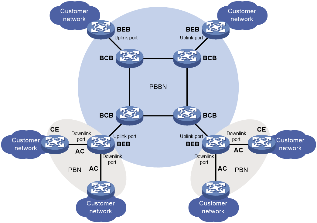
A PBBN contains the following devices:
· Backbone edge bridges (BEBs)—Edge devices in the PBBN. A BEB encapsulates frames from a customer network by using PBB. It decapsulates PBB frames from the PBBN and forwards them to a customer network. BEBs learn customer MAC addresses.
¡ A port that connects a BEB to the PBBN is an uplink port. After frames from the customer network are encapsulated in PBB frames, the frames are forwarded out of the corresponding uplink ports on the BEB.
¡ A port that connects a BEB to a customer network is a downlink port. After PBB frames from the PBBN are decapsulated, the frames are forwarded out of the corresponding downlink ports on the BEB according to the customer MAC addresses.
¡ An attachment circuit (AC) is a physical or virtual link that connects a CE to a BEB.
· Backbone core bridges (BCBs)—Core devices in the PBBN. They forward PBB frames according to B-MACs and B-VLANs. A BCB only forwards frames and learns MAC addresses within the PBBN. It does not learn a large number of customer MAC addresses. This reduces network deployment costs, and the PBBN is more expandable.
· Customer edges (CEs)—Edge devices that connect customer sites or PBNs to BEBs of the PBBN.
Terminology
· B-MAC and B-VLAN
A backbone MAC address (B-MAC) is a MAC address associated with a PBB bridge. A backbone VLAN (B-VLAN) is a VLAN assigned by the service provider for transmitting customer traffic on the PBBN.
For customer frames to be transmitted across a PBBN, the ingress BEB encapsulates them in MAC-in-MAC format. In the outer frame header, the source MAC address is a B-MAC of the ingress BEB, and the destination MAC is a B-MAC of the egress BEB. All devices in the PBBN forward the PBB frames based on the destination B-MAC and B-VLAN.
· PBB VSI and I-SID
PBB frame format
Figure 2 shows the format of a PBB frame.
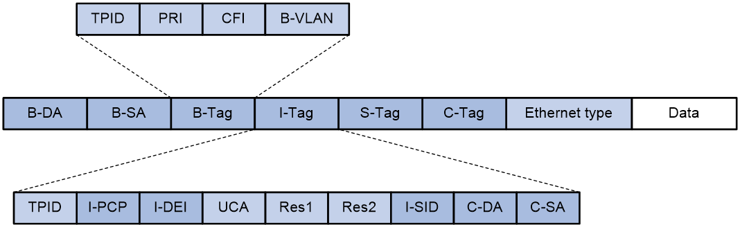
Table 1 describes key fields in the frame.
Table 1 PBB frame fields
|
Field |
Full name |
Description |
|
B-DA |
Backbone destination MAC address |
Destination B-MAC, outer destination MAC address in a PBB frame. It is the MAC address of the BEB at the destination end of the PBBN tunnel. The combination of B-DA and B-SA is B-MAC. |
|
B-SA |
Backbone source MAC address |
Source B-MAC, outer source MAC address in a PBB frame. It is the MAC address of the BEB at the source end of the PBBN tunnel. The combination of B-DA and B-SA is B-MAC. |
|
B-Tag |
Backbone VLAN tag |
B-VLAN tag, outer VLAN tag in a PBB frame. It indicates the VLAN information and priority information of the frame within the PBBN. The TPID in a B-Tag is 0x8100. |
|
I-Tag |
Backbone service instance tag |
Service identifier of a PBB frame. The I-Tag contains the following fields: · TPID—The TPID in an I-Tag is 0x88E7. · I-PCP—Backbone service instance priority code point. · I-DEI—Backbone service instance drop eligibility indicator. · I-SID—Backbone service instance identifier. · C-DA—Destination MAC address of the customer frame. · C-SA—Source MAC address of the customer frame. |
|
S-Tag |
Service provider VLAN tag |
Outer VLAN tag of the frame in the PBN, which indicates the VLAN and priority information of the frame within the PBN. |
|
C-Tag |
Customer VLAN tag |
Inner VLAN tag of the frame in the PBN, which indicates the VLAN and priority information of the frame within the customer network. |
For more information about TPID, see "Configuring VLANs."
PBB frame forwarding
On a PBBN, the BEBs encapsulate customer traffic in PBB, and learn their C-MAC reachability information in the data plane. To forward traffic across the PBBN, the BEBs learn unicast forwarding entries for reaching each other. Each entry contains a B-MAC address, B-VLAN, I-SID, and outgoing interface.
The following describes how a unicast forwarding entry is created:
1. When BEB 1 receives a frame with an unknown destination C-MAC (for example, MAC A) from the customer network, BEB 1 performs the following operations:
a. Assign the frame to a PBB VSI based on the configured match criteria.
b. Encapsulates the frame in MAC-in-MAC format. The source B-MAC is the MAC address of BEB 1. The destination B-MAC is the multicast B-MAC configured for the matching PBB VSI.
c. Multicasts the PBB frame out of the VSI's all uplink ports.
2. When BEB 2 receives the PBB frame, it performs the following operations:
a. Creates a unicast forwarding entry for MAC A. In the entry, the destination B-MAC is the B-MAC of BEB 1, the outgoing interface is the interface on which the frame was received.
b. Removes the PBB encapsulation, and then forwards the frame to the customer network.
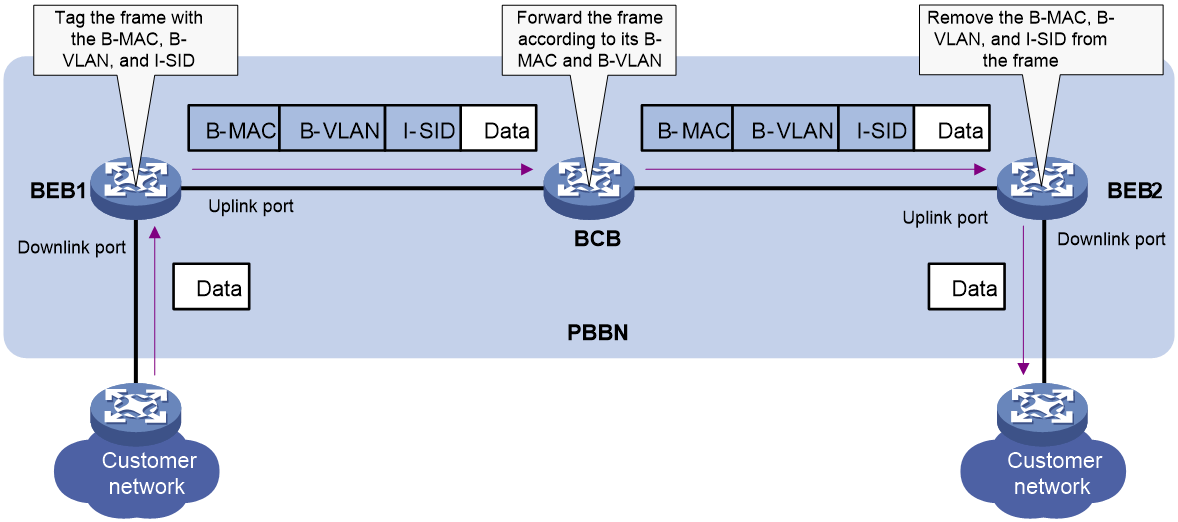
Figure 3 shows how the PBBN forwards a frame between BEBs if a unicast forwarding entry exists for the frame:
1. BEB 1 encapsulates a customer frame with the matching source and destination B-MACs, B-VLAN, and I-SID. Then it forwards the frame to the BCB through its uplink port.
2. BCB forwards the PBB frame from BEB 1 to BEB 2 according to the frame's destination B-MAC and B-VLAN.
3. BEB 2 removes the PBB encapsulation, and then forwards the original Ethernet frame out of the downlink port to the customer network.
PBB data encapsulation types
A PBB VSI supports Ethernet and VLAN data encapsulation types.
A data encapsulation type decides how the BEB handles the P-tag on a PBB VSI, as shown in Table 2. P-tags are unique VLAN tags that the service provider assigns to users for differentiation.
The access mode determines how a BEB considers the VLAN tag in Ethernet frames received from a CE and how the BEB forwards Ethernet frames to the CE.
· VLAN access mode—Ethernet frames received from the CE must carry a VLAN tag in the Ethernet header. The BEB considers the VLAN tag as a P-tag assigned by the service provider. Ethernet frames sent to the CE must also carry the P-tag.
· Ethernet access mode—If Ethernet frames from the CE have a VLAN tag in the header, the PE considers it as a U-tag and ignores it. Ethernet frames sent to the CE do not carry the P-tag.
|
Traffic direction |
Ethernet encapsulation |
VLAN encapsulation |
|
CE to PBBN |
The traffic must not contain a P-tag. · VLAN access mode—The BEB removes the P-tag before it encapsulates the traffic in PBB. · Ethernet access mode—The BEB directly encapsulates the traffic in PBB. The VLAN tag in the received traffic is considered a U-tag. |
The traffic must contain a P-tag. · VLAN access mode—The BEB retains the P-tag or changes the P-tag to the value assigned by the peer BEB. · Ethernet access mode—The BEB adds the P-tag assigned by the peer BEB. The original VLAN tag in the received traffic is considered a U-tag. The P-tag assigned by the peer BEB might be a null tag (tag 0). |
|
PBBN to CE |
· VLAN access mode—The BEB adds a P-tag before it forwards the traffic. · Ethernet access mode—The BEB forwards the traffic without adding a P-tag. The BEB cannot modify or remove any tags already in the traffic from PBBN to CE. |
· VLAN access mode—The BEB forwards the traffic with the P-tag modified or intact. · Ethernet access mode—The BEB removes the P-tag before it forwards the traffic. |
Protocols and standards
IEEE 802.1ah, Virtual Bridged Local Area Networks Amendment 7: Provider Backbone Bridges
Restrictions: Hardware compatibility with PBB
The S6820 switch series and S6861 switch series do not support PBB.
PBB tasks at a glance
You need to configure PBB only on BEBs. On BCBs, you must create VLANs that are the same as the B-VLANs used on the BEBs.
To configure PBB, perform the following tasks:
3. Configuring a B-VLAN for a PBB VSI
5. Configuring a downlink port
6. (Optional.) Configuring the data encapsulation type
Enabling L2VPN
Restrictions and guidelines
For PBB settings to take effect, you must enable L2VPN.
Procedure
1. Enter system view.
system-view
2. Enable L2VPN.
l2vpn enable
By default, L2VPN is disabled.
Creating a PBB VSI
Restrictions and guidelines
You can configure one PBB I-SID and one SPB I-SID for a VSI, but the two I-SIDs must be different. For more information about SPB, see SPB Configuration Guide.
You must assign a unique I-SID to each PBB VSI.
The name of a PBB VSI can be different on different PBB nodes, but its I-SID must be the same across the PBBN.
Procedure
1. Enter system view.
system-view
2. Create a VSI and enter VSI view.
vsi vsi-name
3. Configure the VSI as a PBB VSI, specify a PBB I-SID for the PBB VSI, and enter PBB VSI view.
pbb i-sid i-sid
Configuring a B-VLAN for a PBB VSI
Restrictions and guidelines
You can assign only one B-VLAN to a PBB VSI, but different PBB VSIs can use the same B-VLAN.
For a PBB VSI, you must specify the same I-SID and B-VLAN across all BEBs.
Procedure
1. Enter system view.
system-view
2. Enter VSI view.
vsi vsi-name
3. Configure the VSI as a PBB VSI, specify a PBB I-SID for the PBB VSI, and enter PBB VSI view.
pbb i-sid i-sid
4. Specify a B-VLAN for the PBB VSI.
bvlan vlan-id
By default, no B-VLAN is specified for a PBB VSI.
Configuring an uplink port
About uplink port configuration
On the BEB, you must specify uplink ports for a PBB VSI to forward frames from the customer network to the service provider network.
Restrictions and guidelines
You can specify multiple uplink ports for one PBB VSI. The device automatically selects uplink ports for packets. The uplink ports cannot be member ports in a link aggregation group.
For the uplink port configuration to take effect, perform the following tasks before uplink port assignment:
· Assign a B-VLAN to the PBB VSI.
· Verify that the port is in up state and is not a link aggregation group member.
· Assign the port to the B-VLAN.
Procedure
1. Enter system view.
system-view
2. Enter Layer 2 Ethernet interface view or Layer 2 aggregate interface view.
interface interface-type interface-number
3. Specify the port as the uplink port for the specified or all PBB VSIs.
pbb uplink { all | vsi vsi-name-list }
By default, a port is not configured as the uplink port of any PBB VSI.
Configuring a downlink port
Restrictions and guidelines
You can specify one or multiple downlink ports for a PBB VSI.
Do not assign a downlink port to a B-VLAN.
You can create Ethernet service instances on both a Layer 2 aggregate interface and its member ports and map the Ethernet service instances to VSIs. However, the Ethernet service instances on the aggregation member ports are down. For the Ethernet service instances to come up, you must remove the aggregation member ports from the aggregation group.
Procedure
1. Enter system view.
system-view
2. Enter Layer 2 Ethernet interface view or Layer 2 aggregate interface view.
interface interface-type interface-number
3. Create an Ethernet service instance and enter Ethernet service instance view.
service-instance instance-id
4. Choose one of the following commands to configure a match criterion:
¡ encapsulation s-vid vlan-id [ c-vid { vlan-id-list | all } | only-tagged ]
¡ encapsulation s-vid vlan-id-list [ c-vid vlan-id-list ]
¡ encapsulation { default | tagged | untagged }
By default, no match criterion is configured.
For more information about the encapsulation commands, see MPLS Command Reference.
5. Map the Ethernet service instance to a PBB VSI.
xconnect vsi vsi-name [ access-mode { ethernet | vlan } ]
By default, an Ethernet service instance is not mapped to any PBB VSI.
For more information about the xconnect command, see MPLS Command Reference.
Configuring the data encapsulation type
1. Enter system view.
system-view
2. Enter VSI view.
vsi vsi-name
3. Enter PBB VSI view.
pbb i-sid i-sid
4. Specify an encapsulation type for the PBB VSI.
encapsulation { ethernet | vlan }
By default, VLAN encapsulation applies.
Display and maintenance commands for PBB
Execute display commands in any view and reset commands in user view.
|
Task |
Command |
|
Display PBB VSI connections. |
display pbb connection [ vsi vsi-name ] |
|
Display MAC-in-MAC connections. |
display l2vpn minm connection [ vsi vsi-name ] |
|
Display MAC-in-MAC forwarding entries. |
display l2vpn minm forwarding [ vsi vsi-name ] [ slot slot-number ] |
|
Display VSI information. |
display l2vpn vsi [ name vsi-name ] [ verbose ] |
|
Clear PBB VSI connections. |
reset pbb connection [ { bvlan vlan-id | interface interface-type interface-number } * | vsi vsi-name ] |
PBB configuration examples
Example: Configuring a basic PBB network
Network configuration
As shown in Figure 4, configure PBB to provide connectivity between network A and network B of a customer.
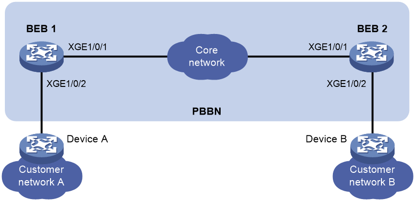
Procedure
1. Configure BEB 1:
# Create VLAN 20.
<BEB1> system-view
[BEB1] vlan 20
[BEB1-vlan20] quit
# Enable L2VPN.
[BEB1] l2vpn enable
# Create a VSI of the PBB type.
[BEB1] vsi aaa
# Specify the I-SID as 1.
[BEB1-vsi-aaa] pbb i-sid 1
# Specify B-VLAN 20 for the PBB VSI.
[BEB1-vsi-aaa-1] bvlan 20
[BEB1-vsi-aaa-1] quit
[BEB1-vsi-aaa] quit
# Configure Ten-GigabitEthernet 1/0/1 as a trunk port, assign it to VLAN 20, and configure it as an uplink port of the PBB VSI.
[BEB1] interface ten-gigabitethernet 1/0/1
[BEB1-Ten-GigabitEthernet1/0/1] port link-type trunk
[BEB1-Ten-GigabitEthernet1/0/1] port trunk permit vlan 20
[BEB1-Ten-GigabitEthernet1/0/1] pbb uplink vsi aaa
[BEB1-Ten-GigabitEthernet1/0/1] quit
# Create Ethernet service instance 1 on Ten-GigabitEthernet 1/0/2.
[BEB1] interface ten-gigabitethernet 1/0/2
[BEB1-Ten-GigabitEthernet1/0/2] service-instance 1
# Configure the Ethernet service instance to match all 802.1Q tagged frames. Map the service instance to the PBB VSI, and set the access mode to Ethernet.
[BEB1-Ten-GigabitEthernet1/0/2-srv1] encapsulation tagged
[BEB1-Ten-GigabitEthernet1/0/2-srv1] xconnect vsi aaa access-mode ethernet
[BEB1-Ten-GigabitEthernet1/0/2-srv1] quit
[BEB1-Ten-GigabitEthernet1/0/2] quit
# Configure Ethernet encapsulation for the PBB VSI.
[BEB1] vsi aaa
[BEB1-vsi-aaa] pbb i-sid 1
[BEB1-vsi-aaa-1] encapsulation ethernet
[BEB1-vsi-aaa-1] quit
2. Configure BEB 2 in the same way BEB 1 is configured. (Details not shown.)
Verifying the configuration
# Display PBB VSI connections on BEB 1.
[BEB1] display pbb connection vsi aaa
BMAC BVLAN Port Type Aging
011e-8300-0001 20 XGE1/0/1 MC N
000f-e200-0001 20 XGE1/0/1 UC Y
# Verify that Device A and Device B can ping each other. (Details not shown.)
Troubleshooting PBB
Failed to transmit customer frames to peer
Symptom
Customer frames cannot be transmitted to the peer network by using PBB.
Solution
To resolve the issue:
1. Use the display l2vpn vsi verbose command to display the PBB configuration of the VSI.
¡ If the VSI is not configured as a PBB VSI, configure the VSI as a PBB VSI.
¡ If the VSI is down, use the undo shutdown command to bring the VSI up.
2. Use the display l2vpn vsi verbose command to verify that the VSI's PBB settings are consistent across BEBs, especially the I-SID and B-VLAN settings.
3. Use the display vlan all command to verify that the following settings are configured on all BCBs:
¡ The B-VLAN is created on each BCB.
¡ All ports on the path between the BEBs are assigned to the B-VLAN.
4. If the issue persists, contact H3C Support.
