- Table of Contents
-
- 03-Layer 2—LAN Switching Configuration Guide
- 00-Preface
- 01-MAC address table configuration
- 02-Bulk interface configuration
- 03-Ethernet interface configuration
- 04-Ethernet link aggregation configuration
- 05-DRNI configuration
- 06-Port isolation configuration
- 07-VLAN configuration
- 08-MVRP configuration
- 09-Loopback, null, and inloopback interface configuration
- 10-QinQ configuration
- 11-VLAN mapping configuration
- 12-PBB configuration
- 13-Loop detection configuration
- 14-Spanning tree configuration
- 15-LLDP configuration
- 16-L2PT configuration
- 17-Service loopback group configuration
- 18-Cut-through Layer 2 forwarding configuration
- Related Documents
-
| Title | Size | Download |
|---|---|---|
| 11-VLAN mapping configuration | 367.32 KB |
Contents
VLAN mapping application scenarios
Restrictions and guidelines: VLAN mapping configuration
VLAN mapping tasks at a glance
Configuring one-to-one VLAN mapping
Configuring many-to-one VLAN mapping
About many-to-one VLAN mapping
Configuring many-to-one VLAN mapping in dynamic IP address assignment environment
Configuring many-to-one VLAN mapping in static IP address assignment environment
Configuring one-to-two VLAN mapping
Configuring two-to-one VLAN mapping
Configuring two-to-two VLAN mapping
Display and maintenance commands for VLAN mapping
VLAN mapping configuration examples
Example: Configuring one-to-one and many-to-one VLAN mapping
Example: Configuring one-to-two and two-to-two VLAN mapping
Configuring VLAN mapping
About VLAN mapping
VLAN mapping re-marks VLAN traffic with new VLAN IDs.
VLAN mapping types
H3C provides the following types of VLAN mapping:
· One-to-one VLAN mapping—Replaces one VLAN tag with another.
· Many-to-one VLAN mapping—Replaces multiple VLAN tags with the same VLAN tag.
· One-to-two VLAN mapping—Tags single-tagged packets with an outer VLAN tag.
· Two-to-one VLAN mapping—Removes VLAN tags from double-tagged packets and adds a new VLAN tag to them.
· Two-to-two VLAN mapping—Replaces the outer and inner VLAN IDs of double tagged traffic with a new pair of VLAN IDs.
VLAN mapping application scenarios
One-to-one and many-to-one VLAN mapping
One-to-one and many-to-one VLAN mapping are typically used by a community for broadband Internet access, as shown in Figure 1.
Figure 1 Application scenario of one-to-one and many-to-one VLAN mapping
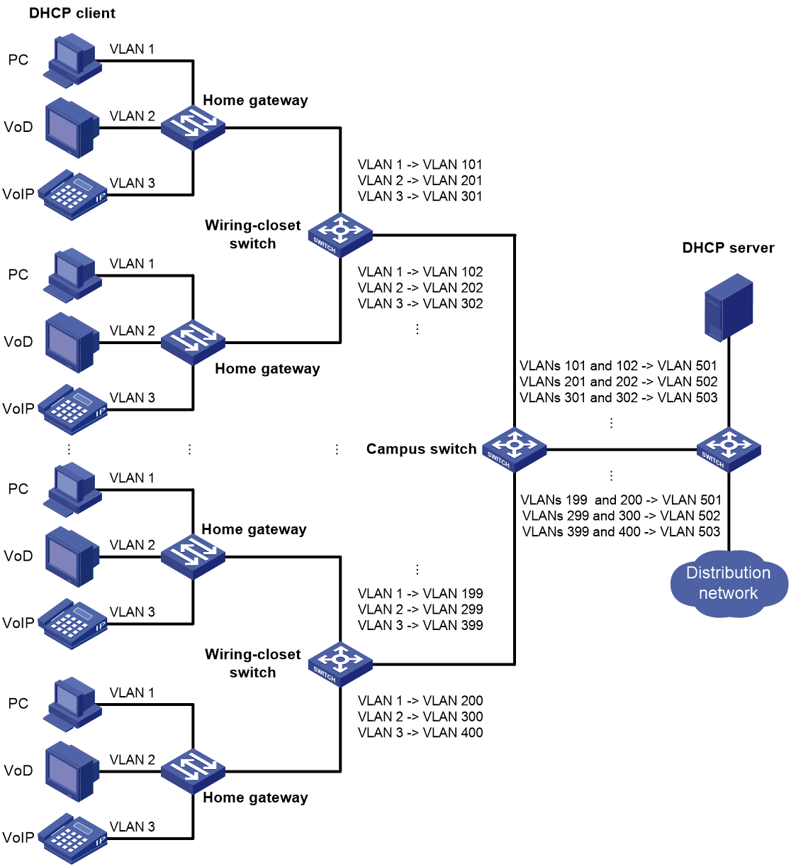
As shown in Figure 1, the network is implemented as follows:
· Each home gateway uses different VLANs to transmit the PC, VoD, and VoIP services.
· To further subclassify each type of traffic by customer, configure one-to-one VLAN mapping on the wiring-closet switches. This feature assigns a separate VLAN to each type of traffic from each customer. The required total number of VLANs in the network can be very large.
One-to-two and two-to-two VLAN mapping
One-to-two and two-to-two VLAN mapping are typically used to implement communication across different SP networks, as shown in Figure 2.
Figure 2 Application scenario of one-to-two and two-to-two VLAN mapping
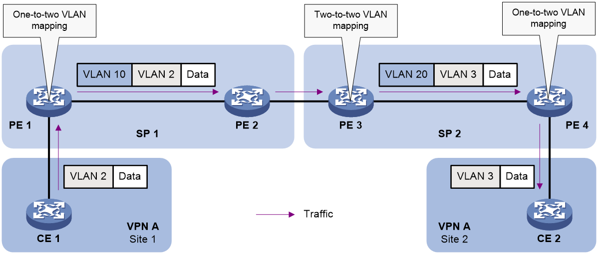
As shown in Figure 2, Site 1 and Site 2 of VPN A are in VLAN 2 and VLAN 3, respectively. The SP 1 network assigns SVLAN 10 to Site 1. The SP 2 network assigns SVLAN 20 to Site 2. When the packet from Site 1 arrives at PE 1, PE 1 tags the packet with SVLAN 10 by using one-to-two VLAN mapping.
When the double-tagged packet from the SP 1 network arrives at the SP 2 network interface, PE 3 processes the packet as follows:
· Replaces SVLAN tag 10 with SVLAN tag 20.
· Replaces CVLAN tag 2 with CVLAN tag 3.
One-to-two VLAN mapping provides the following benefits:
· Enables a customer network to plan its CVLAN assignment without conflicting with SVLANs.
· Adds a VLAN tag to a tagged packet and expands the number of available VLANs to 4094 × 4094.
· Reduces the stress on the SVLAN resources, which were 4094 VLANs in the SP network before the mapping process was initiated.
Two-to-one VLAN mapping
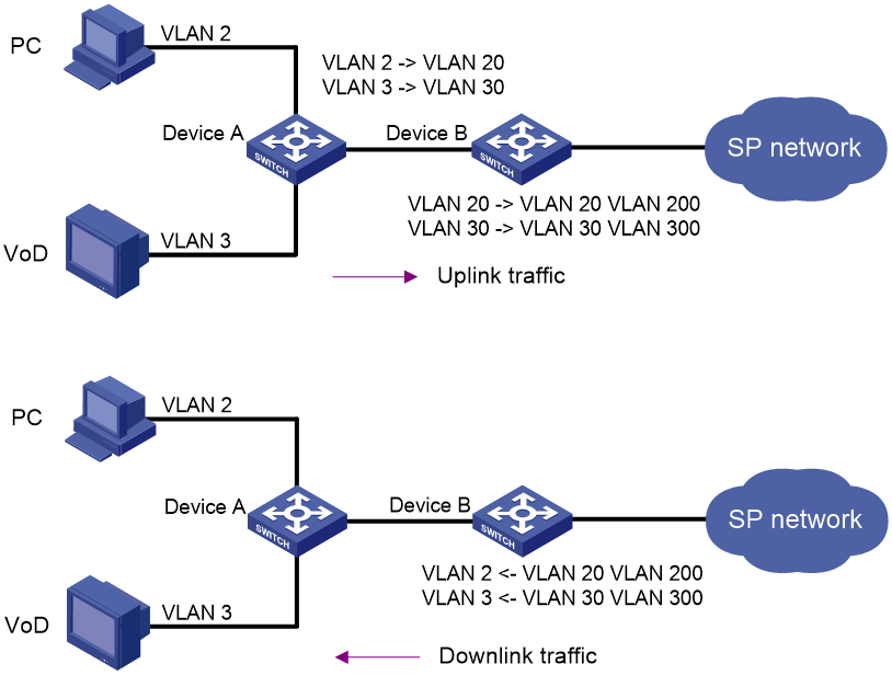
As shown in Figure 3, configure VLANs and VLAN mappings to isolate traffic of different services and ensure the communication between the user network and the service provider network:
· On Device A, assign different types of service traffic to different VLANs.
· On Device B, configure one-to-one VLAN mappings and one-to-two VLAN mappings for uplink traffic.
· On Device B, configure two-to-one VLAN mappings for the downlink traffic. After receiving double-tagged reply packets, Device B removes their double VLAN tags and adds original VLAN tags to them.
Figure 3 Application scenario of two-to-one VLAN mapping
VLAN mapping implementations
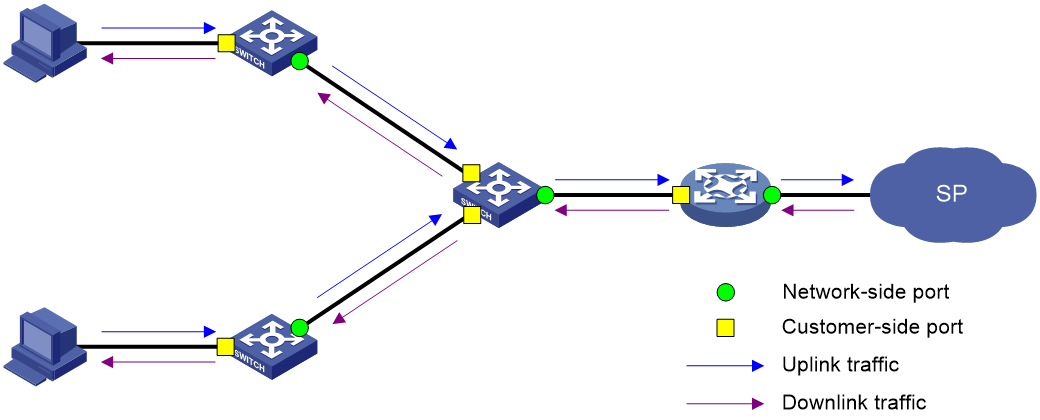
Figure 4 shows a simplified network that illustrates basic VLAN mapping terms.
Basic VLAN mapping terms include the following:
· Uplink traffic—Traffic transmitted from the customer network to the service provider network.
· Downlink traffic—Traffic transmitted from the service provider network to the customer network.
· Network-side port—A port connected to or closer to the service provider network.
· Customer-side port—A port connected to or closer to the customer network.
Figure 4 Basic VLAN mapping terms
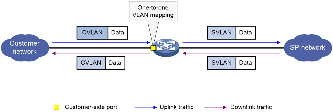
One-to-one VLAN mapping
As shown in Figure 5, one-to-one VLAN mapping is implemented on the customer-side port and replaces VLAN tags as follows:
· Replaces the CVLAN with the SVLAN for the uplink traffic.
· Replaces the SVLAN with the CVLAN for the downlink traffic.
Figure 5 One-to-one VLAN mapping implementation
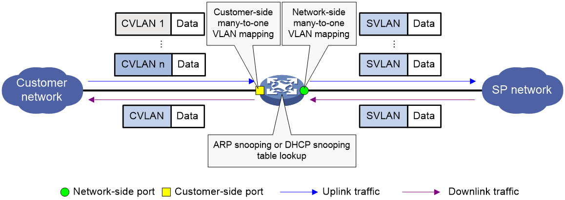
Many-to-one VLAN mapping
As shown in Figure 6, many-to-one VLAN mapping is implemented on both the customer-side and network-side ports as follows:
· For the uplink traffic, the customer-side many-to-one VLAN mapping replaces multiple CVLANs with the same SVLAN.
· For the downlink traffic, the network-side many-to-one VLAN mapping replaces the SVLAN with the CVLAN found in the DHCP snooping table or ARP snooping table. For more information about DHCP snooping and ARP snooping, see Layer 3—IP Services Configuration Guide.
Figure 6 Many-to-one VLAN mapping implementation
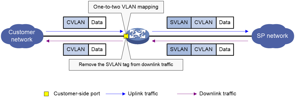
One-to-two VLAN mapping
As shown in Figure 7, one-to-two VLAN mapping is implemented on the customer-side port to add the SVLAN tag for the uplink traffic.
For the downlink traffic to be correctly sent to the customer network, make sure the SVLAN tag is removed on the customer-side port before transmission. Use one of the following methods to remove the SVLAN tag from the downlink traffic:
· Configure the customer-side port as a hybrid port and assign the port to the SVLAN as an untagged member.
· Configure the customer-side port as a trunk port and set the port PVID to the SVLAN.
Figure 7 One-to-two VLAN mapping implementation
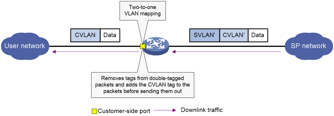
Two-to-one VLAN mapping
As shown in Figure 8, configure two-to-one VLAN mapping on the customer-side port to remove double VLAN tags from downstream packets and add the CVLAN tag to them.
Two-to-one VLAN mapping takes effect only on the outgoing downstream packets of the customer-side port and does not affect the incoming packets of the port.
Figure 8 Two-to-one VLAN mapping implementation
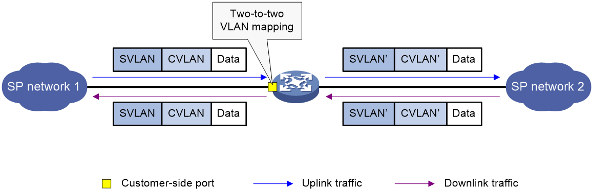
Two-to-two VLAN mapping
As shown in Figure 9, two-to-two VLAN mapping is implemented on the customer-side port and replaces VLAN tags as follows:
· Replaces the CVLAN and the SVLAN with the CVLAN' and the SVLAN' for the uplink traffic.
· Replaces the SVLAN' and CVLAN' with the SVLAN and the CVLAN for the downlink traffic.
Figure 9 Two-to-two VLAN mapping implementation
Restrictions and guidelines: VLAN mapping configuration
To add VLAN tags to packets, you can configure both VLAN mapping and QinQ. VLAN mapping takes effect if a configuration conflict occurs. For more information about QinQ, see "Configuring QinQ."
To add or replace VLAN tags for packets, you can configure both VLAN mapping and a QoS policy. The QoS policy takes effect if a configuration conflict occurs. For information about QoS policies, see ACL and QoS Configuration Guide.
VLAN mapping and the MAC learning limit cannot be configured on the same interface.
VLAN mapping tasks at a glance
Use the appropriate VLAN mapping methods for the devices in the network.
To configure VLAN mapping, perform the following tasks:
· Configuring one-to-one VLAN mapping
Configure one-to-one VLAN mapping on the wiring-closet switch, as shown in Figure 1.
· Configuring many-to-one VLAN mapping
Configure many-to-one VLAN mapping on the campus switch, as shown in Figure 1.
¡ Configuring many-to-one VLAN mapping in dynamic IP address assignment environment
¡ Configuring many-to-one VLAN mapping in static IP address assignment environment
· Configuring one-to-two VLAN mapping
Configure one-to-two VLAN mapping on PE 1 and PE 4, as shown in Figure 2, through which traffic from customer networks enters the service provider networks.
· Configuring two-to-one VLAN mapping
Configure two-to-one VLAN mapping on the customer-side port of Device B, as shown in Figure 3.
· Configuring two-to-two VLAN mapping
Configure two-to-two VLAN mapping on PE 3, as shown in Figure 2, which is an edge device of the SP 2 network.
Prerequisites
Before you configure VLAN mapping, create original and translated VLANs.
Configuring one-to-one VLAN mapping
About one-to-one VLAN mapping
Configure one-to-one VLAN mapping on the customer-side ports of wiring-closet switches (see Figure 1) to isolate traffic of the same service type from different homes.
Procedure
1. Enter system view.
system-view
2. Enter interface view.
¡ Enter Layer 2 Ethernet interface view.
interface interface-type interface-number
¡ Enter Layer 2 aggregate interface view.
interface bridge-aggregation interface-number
3. Set the link type of the port.
port link-type { hybrid | trunk }
By default, the link type of a port is access.
4. Assign the port to the original VLAN and the translated VLAN.
¡ Assign the trunk port to the original VLAN and the translated VLAN.
port trunk permit vlan vlan-id-list
By default, a trunk port is assigned to VLAN 1.
¡ Assign the hybrid port to the original VLAN and the translated VLAN as a tagged member.
port hybrid vlan vlan-id-list tagged
By default, a hybrid port is an untagged member of the VLAN to which the port belongs when its link type is access.
5. Configure a one-to-one VLAN mapping.
vlan mapping vlan-id translated-vlan vlan-id
By default, no VLAN mapping is configured on an interface.
Configuring many-to-one VLAN mapping
About many-to-one VLAN mapping
Configure many-to-one VLAN mapping on campus switches (see Figure 1) to transmit the same type of traffic from different users in one VLAN.
Configuring many-to-one VLAN mapping in dynamic IP address assignment environment
About many-to-one VLAN mapping in dynamic IP address assignment environment
In a network that uses dynamic address assignment, configure many-to-one VLAN mapping with DHCP snooping.
The switch replaces the SVLAN tag of the downlink traffic with the associated CVLAN tag based on the DHCP snooping entry lookup.
Restrictions and guidelines for many-to-one VLAN mapping in dynamic IP address assignment environment
To ensure correct traffic forwarding from the service provider network to the customer network, do not configure many-to-one VLAN mapping together with uRPF. For more information about uRPF, see Security Configuration Guide.
To modify many-to-one VLAN mappings, first use the reset dhcp snooping binding command to clear the DHCP snooping entries.
Many-to-one VLAN mapping in dynamic IP address assignment environment tasks at a glance
To configure many-to-one VLAN mapping in dynamic IP address assignment environment, perform the following tasks:
3. Configuring the customer-side port
4. Configuring the network-side port
Enabling DHCP snooping
1. Enter system view.
system-view
2. Enable DHCP snooping.
dhcp snooping enable
By default, DHCP snooping is disabled.
Enabling ARP detection
1. Enter system view.
system-view
2. Enter VLAN view.
vlan vlan-id
3. Enable ARP detection.
arp detection enable
By default, ARP detection is disabled.
You must enable ARP detection for the original VLANs and the translated VLANs.
Configuring the customer-side port
1. Enter system view.
system-view
2. Enter interface view.
¡ Enter Layer 2 Ethernet interface view.
interface interface-type interface-number
¡ Enter Layer 2 aggregate interface view.
interface bridge-aggregation interface-number
3. Set the link type of the port.
port link-type { hybrid | trunk }
By default, the link type of a port is access.
4. Assign the port to the original VLANs and the translated VLAN.
¡ Assign the trunk port to the original VLANs and the translated VLAN.
port trunk permit vlan vlan-id-list
By default, a trunk port is assigned to VLAN 1.
¡ Assign the hybrid port to the original VLANs and the translated VLAN as a tagged member.
port hybrid vlan vlan-id-list tagged
By default, a hybrid port is an untagged member of the VLAN to which the port belongs when its link type is access.
5. Configure a many-to-one VLAN mapping.
vlan mapping uni { range vlan-range-list | single vlan-id-list } translated-vlan vlan-id
By default, no VLAN mapping is configured on an interface.
6. Enable DHCP snooping entry recording.
dhcp snooping binding record
By default, DHCP snooping entry recording is disabled on an interface.
Configuring the network-side port
1. Enter system view.
system-view
2. Enter interface view.
¡ Enter Layer 2 Ethernet interface view.
interface interface-type interface-number
¡ Enter Layer 2 aggregate interface view.
interface bridge-aggregation interface-number
3. Set the link type of the port.
port link-type { hybrid | trunk }
By default, the link type of a port is access.
4. Assign the port to the translated VLAN.
¡ Assign the trunk port to the translated VLAN.
port trunk permit vlan vlan-id-list
By default, a trunk port is assigned to VLAN 1.
¡ Assign the hybrid port to the translated VLAN as a tagged member.
port hybrid vlan vlan-id-list tagged
By default, a hybrid port is an untagged member of the VLAN to which the port belongs when its link type is access.
5. Configure the port as a DHCP snooping trusted port.
dhcp snooping trust
By default, all ports that support DHCP snooping are untrusted ports when DHCP snooping is enabled.
6. Configure the port as an ARP trusted port.
arp detection trust
By default, all ports are ARP untrusted ports.
7. Configure the port to use the original VLAN tags of the many-to-one mapping to replace the VLAN tags of the packets destined for the user network.
vlan mapping nni
By default, the port does not replace the VLAN tags of the packets destined for the user network.
Configuring many-to-one VLAN mapping in static IP address assignment environment
About many-to-one VLAN mapping in static IP address assignment environment
In a network that uses static IP addresses, configure many-to-one VLAN mapping with ARP snooping.
The switch replaces the SVLAN tag of the downlink traffic with the associated CVLAN tag based on the ARP snooping entry lookup.
Restrictions and guidelines for many-to-one VLAN mapping in static IP address assignment environment
When you configure many-to-one VLAN mapping in a network that uses static address assignment, follow these restrictions and guidelines:
· Make sure hosts in different CVLANs do not use the same IP address.
· When an IP address is no longer associated with the MAC address and VLAN in an ARP snooping entry, wait for this entry to be aged out. You can also use the reset arp snooping ip ip-address command to clear the entry.
· Before you modify many-to-one VLAN mapping, use the reset arp snooping vlan vlan-id command to clear the ARP snooping entries in each CVLAN.
· To ensure correct traffic forwarding from the service provider network to the customer network, do not configure many-to-one VLAN mapping together with uRPF. For more information about uRPF, see Security Configuration Guide.
Many-to-one VLAN mapping in static IP address assignment environment tasks at a glance
To configure many-to-one VLAN mapping in static IP address assignment environment, perform the following tasks:
2. Configuring the customer-side port
3. Configuring the network-side port
Enabling ARP snooping
1. Enter system view.
system-view
2. Enter VLAN view.
vlan vlan-id
3. Enable ARP snooping.
arp snooping enable
By default, ARP snooping is disabled.
You must enable ARP snooping for the original VLANs and the translated VLANs.
Configuring the customer-side port
1. Enter system view.
system-view
2. Enter interface view.
¡ Enter Layer 2 Ethernet interface view.
interface interface-type interface-number
¡ Enter Layer 2 aggregate interface view.
interface bridge-aggregation interface-number
3. Set the link type of the port.
port link-type { hybrid | trunk }
By default, the link type of a port is access.
4. Assign the port to the original VLANs and the translated VLAN.
¡ Assign the trunk port to the original VLANs and the translated VLAN.
port trunk permit vlan vlan-id-list
By default, a trunk port is assigned to VLAN 1.
¡ Assign the hybrid port to the original VLANs and the translated VLAN as a tagged member.
port hybrid vlan vlan-id-list tagged
By default, a hybrid port is an untagged member of the VLAN to which the port belongs when its link type is access.
5. Configure a many-to-one VLAN mapping.
vlan mapping uni { range vlan-range-list | single vlan-id-list } translated-vlan vlan-id
By default, no VLAN mapping is configured on an interface.
Configuring the network-side port
1. Enter system view.
system-view
2. Enter interface view.
¡ Enter Layer 2 Ethernet interface view.
interface interface-type interface-number
¡ Enter Layer 2 aggregate interface view.
interface bridge-aggregation interface-number
3. Set the link type of the port.
port link-type { hybrid | trunk }
By default, the link type of a port is access.
4. Assign the port to the translated VLAN.
¡ Assign the trunk port to the translated VLAN.
port trunk permit vlan vlan-id-list
By default, a trunk port is assigned to VLAN 1.
¡ Assign the hybrid port to the translated VLAN as a tagged member.
port hybrid vlan vlan-id-list tagged
By default, a hybrid port is an untagged member of the VLAN to which the port belongs when its link type is access.
5. Configure the port to use the original VLAN tags of the many-to-one mapping to replace the VLAN tags of the packets destined for the user network.
vlan mapping nni
By default, the port does not replace the VLAN tags of the packets destined for the user network.
Configuring one-to-two VLAN mapping
About one-to-two VLAN mapping
Configure one-to-two VLAN mapping on the customer-side ports of edge devices from which customer traffic enters SP networks, for example, on PEs 1 and 4 in Figure 2. One-to-two VLAN mapping enables the edge devices to add an SVLAN tag to each incoming packet.
Restrictions and guidelines
Only one SVLAN tag can be added to packets from the same CVLAN. To add different SVLAN tags to different CVLAN packets on a port, set the port link type to hybrid and configure multiple one-to-two VLAN mappings.
The MTU of an interface is 1500 bytes by default. After a VLAN tag is added to a packet, the packet length is added by 4 bytes. As a best practice, set the MTU to a minimum of 1504 bytes for ports on the forwarding path of the packet in the service provider network.
Procedure
1. Enter system view.
system-view
2. Enter interface view.
¡ Enter Layer 2 Ethernet interface view.
interface interface-type interface-number
¡ Enter Layer 2 aggregate interface view.
interface bridge-aggregation interface-number
3. Set the link type of the port.
port link-type { hybrid | trunk }
By default, the link type of a port is access.
4. Configure the port to allow packets from the SVLAN to pass through untagged.
¡ Configure the SVLAN as the PVID of the trunk port and assign the trunk port to the SVLAN.
port trunk pvid vlan vlan-id
port trunk permit vlan { vlan-id-list | all }
¡ Assign the hybrid port to the SVLAN as an untagged member.
port hybrid vlan vlan-id-list untagged
5. Configure a one-to-two VLAN mapping.
vlan mapping nest { range vlan-range-list | single vlan-id-list } nested-vlan vlan-id
By default, no VLAN mapping is configured on an interface.
Configuring two-to-one VLAN mapping
About two-to-one VLAN mapping
Configure two-to-one VLAN mapping on the customer-side port of Device B, as shown in Figure 3. Device B will remove VLAN tags from double-tagged packets and add the CVLAN tag to them. When packets arrives Device A, Device A removes the CVLAN tag.
Restrictions and guidelines
On an interface, the original CVLAN and SVLAN of a two-to-one VLAN mapping cannot be the same as the translated CVLAN and SVLAN of a two-to-two VLAN mapping.
You cannot specify multiple translated VLANs for the same original CVLAN and SVLAN on an interface. To modify an existing two-to-one VLAN mapping on an interface, you must execute the undo vlan mapping egress command to remove it first and then configure a new mapping.
Procedure
1. Enter system view.
system-view
2. Enter interface view.
¡ Enter Layer 2 Ethernet interface view.
interface interface-type interface-number
¡ Enter Layer 2 aggregate interface view.
interface bridge-aggregation interface-number
3. Set the port link type to hybrid or trunk.
port link-type { hybrid | trunk }
By default, the link type of a port is access.
4. Assign the port to the translated VLAN.
¡ Assign the trunk port to the translated VLAN.
port trunk permit vlan vlan-id-list
By default, a trunk port is assigned to VLAN 1.
¡ Assign the hybrid port to the translated VLAN.
port hybrid vlan vlan-id-list tagged
By default, a hybrid port is an untagged member of the VLAN to which the port belongs when its link type is access.
5. Configure a two-to-one VLAN mapping.
vlan mapping egress outer-vlan outer-vlan-id inner-vlan inner-vlan-id translated-vlan vlan-id
By default, no VLAN mapping is configured on an interface.
Configuring two-to-two VLAN mapping
About two-to-two VLAN mapping
Configure two-to-two VLAN mapping on the customer-side port of an edge device that connects two SP networks, for example, on PE 3 in Figure 2. Two-to-two VLAN mapping enables two sites in different VLANs to communicate at Layer 2 across two service provider networks that use different VLAN assignment schemes.
Procedure
1. Enter system view.
system-view
2. Enter interface view.
¡ Enter Layer 2 Ethernet interface view.
interface interface-type interface-number
¡ Enter Layer 2 aggregate interface view.
interface bridge-aggregation interface-number
3. Set the link type of the port.
port link-type { hybrid | trunk }
By default, the link type of a port is access.
4. Assign the port to the original VLANs and the translated VLANs.
¡ Assign the trunk port to the original VLANs and the translated VLANs.
port trunk permit vlan vlan-id-list
By default, a trunk port is assigned to VLAN 1.
¡ Assign the hybrid port to the original VLANs and the translated VLANs as a tagged member.
port hybrid vlan vlan-id-list tagged
By default, a hybrid port is an untagged member of the VLAN to which the port belongs when its link type is access.
5. Configure a two-to-two VLAN mapping.
vlan mapping tunnel outer-vlan-id inner-vlan-id translated-vlan outer-vlan-id inner-vlan-id
By default, no VLAN mapping is configured on an interface.
Display and maintenance commands for VLAN mapping
Execute display commands in any view.
|
Task |
Command |
|
Display VLAN mapping information. |
display vlan mapping [ interface interface-type interface-number ] |
VLAN mapping configuration examples
Example: Configuring one-to-one and many-to-one VLAN mapping
Network configuration
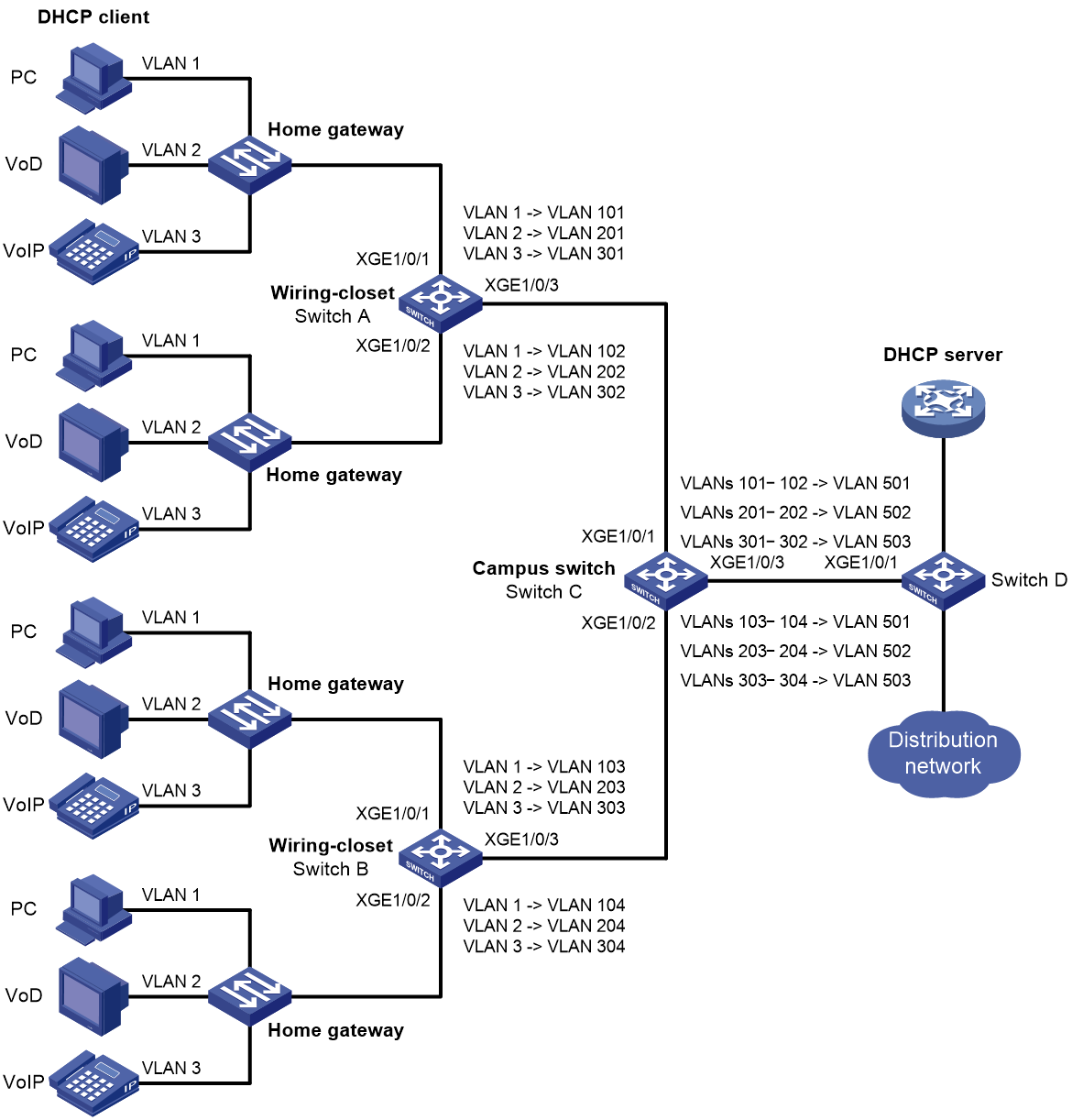
As shown in Figure 10:
· Each household subscribes to PC, VoD, and VoIP services, and obtains the IP address through DHCP.
· On the home gateways, VLANs 1, 2, and 3 are assigned to PC, VoD, and VoIP traffic, respectively.
To isolate traffic of the same service type from different households, configure one-to-one VLAN mappings on the wiring-closet switches. This feature assigns one VLAN to each type of traffic from each household.
To save VLAN resources, configure many-to-one VLAN mappings on the campus switch (Switch C). This feature transmits the same type of traffic from different households in one VLAN. Use VLANs 501, 502, and 503 for PC, VoD, and VoIP traffic, respectively.
Table 1 VLAN mappings for each service
|
Service |
VLANs on home gateways |
VLANs on wiring-closet switches (Switch A and Switch B) |
VLANs on campus switch (Switch C) |
|
PC |
VLAN 1 |
VLANs 101, 102, 103, 104 |
VLAN 501 |
|
VoD |
VLAN 2 |
VLANs 201, 202, 203, 204 |
VLAN 502 |
|
VoIP |
VLAN 3 |
VLANs 301, 302, 303, 304 |
VLAN 503 |
Procedure
1. Configure Switch A:
# Create the original VLANs.
<SwitchA> system-view
[SwitchA] vlan 2 to 3
# Create the translated VLANs.
[SwitchA] vlan 101 to 102
[SwitchA] vlan 201 to 202
[SwitchA] vlan 301 to 302
# Configure customer-side port Ten-GigabitEthernet 1/0/1 as a trunk port.
<SwitchA> system-view
[SwitchA] interface ten-gigabitethernet 1/0/1
[SwitchA-Ten-GigabitEthernet1/0/1] port link-type trunk
# Assign Ten-GigabitEthernet 1/0/1 to all original VLANs and translated VLANs.
[SwitchA-Ten-GigabitEthernet1/0/1] port trunk permit vlan 1 2 3 101 201 301
# Configure one-to-one VLAN mappings on Ten-GigabitEthernet 1/0/1 to map VLANs 1, 2, and 3 to VLANs 101, 201, and 301, respectively.
[SwitchA-Ten-GigabitEthernet1/0/1] vlan mapping 1 translated-vlan 101
[SwitchA-Ten-GigabitEthernet1/0/1] vlan mapping 2 translated-vlan 201
[SwitchA-Ten-GigabitEthernet1/0/1] vlan mapping 3 translated-vlan 301
[SwitchA-Ten-GigabitEthernet1/0/1] quit
# Configure customer-side port Ten-GigabitEthernet 1/0/2 as a trunk port.
[SwitchA] interface ten-gigabitethernet 1/0/2
[SwitchA-Ten-GigabitEthernet1/0/2] port link-type trunk
# Assign Ten-GigabitEthernet 1/0/2 to all original VLANs and translated VLANs.
[SwitchA-Ten-GigabitEthernet1/0/2] port trunk permit vlan 1 2 3 102 202 302
# Configure one-to-one VLAN mappings on Ten-GigabitEthernet 1/0/2 to map VLANs 1, 2, and 3 to VLANs 102, 202, and 302, respectively.
[SwitchA-Ten-GigabitEthernet1/0/2] vlan mapping 1 translated-vlan 102
[SwitchA-Ten-GigabitEthernet1/0/2] vlan mapping 2 translated-vlan 202
[SwitchA-Ten-GigabitEthernet1/0/2] vlan mapping 3 translated-vlan 302
[SwitchA-Ten-GigabitEthernet1/0/2] quit
# Configure the network-side port (Ten-GigabitEthernet 1/0/3) as a trunk port.
[SwitchA] interface ten-gigabitethernet 1/0/3
[SwitchA-Ten-GigabitEthernet1/0/3] port link-type trunk
# Assign Ten-GigabitEthernet 1/0/3 to the translated VLANs.
[SwitchA-Ten-GigabitEthernet1/0/3] port trunk permit vlan 101 201 301 102 202 302
[SwitchA-Ten-GigabitEthernet1/0/3] quit
2. Configure Switch B in the same way Switch A is configured. (Details not shown.)
3. Configure Switch C:
# Enable DHCP snooping.
<SwitchC> system-view
[SwitchC] dhcp snooping enable
# Create the original VLANs and translated VLANs, and enable ARP detection for these VLANs.
[SwitchC] vlan 101
[SwitchC-vlan101] arp detection enable
[SwitchC-vlan101] vlan 201
[SwitchC-vlan201] arp detection enable
[SwitchC-vlan201] vlan 301
[SwitchC-vlan301] arp detection enable
[SwitchC-vlan301] vlan 102
[SwitchC-vlan102] arp detection enable
[SwitchC-vlan102] vlan 202
[SwitchC-vlan202] arp detection enable
[SwitchC-vlan202] vlan 302
[SwitchC-vlan302] arp detection enable
[SwitchC-vlan302] vlan 103
[SwitchC-vlan103] arp detection enable
[SwitchC-vlan103] vlan 203
[SwitchC-vlan203] arp detection enable
[SwitchC-vlan203] vlan 303
[SwitchC-vlan303] arp detection enable
[SwitchC-vlan303] vlan 104
[SwitchC-vlan104] arp detection enable
[SwitchC-vlan104] vlan 204
[SwitchC-vlan204] arp detection enable
[SwitchC-vlan204] vlan 304
[SwitchC-vlan304] arp detection enable
[SwitchC-vlan304] vlan 501
[SwitchC-vlan501] arp detection enable
[SwitchC-vlan501] vlan 502
[SwitchC-vlan502] arp detection enable
[SwitchC-vlan502] vlan 503
[SwitchC-vlan503] arp detection enable
[SwitchC-vlan503] quit
# Configure customer-side port Ten-GigabitEthernet 1/0/1 as a trunk port.
[SwitchC] interface ten-gigabitethernet 1/0/1
[SwitchC-Ten-GigabitEthernet1/0/1] port link-type trunk
# Assign Ten-GigabitEthernet 1/0/1 to all original VLANs and translated VLANs.
[SwitchC-Ten-GigabitEthernet1/0/1] port trunk permit vlan 101 102 201 202 301 302 501 to 503
# Configure many-to-one VLAN mappings on Ten-GigabitEthernet 1/0/1 to map VLANs for PC, VoD, and VoIP traffic to VLANs 501, 502, and 503, respectively.
[SwitchC-Ten-GigabitEthernet1/0/1] vlan mapping uni range 101 to 102 translated-vlan 501
[SwitchC-Ten-GigabitEthernet1/0/1] vlan mapping uni range 201 to 202 translated-vlan 502
[SwitchC-Ten-GigabitEthernet1/0/1] vlan mapping uni range 301 to 302 translated-vlan 503
# Enable DHCP snooping entry recording on Ten-GigabitEthernet 1/0/1.
[SwitchC-Ten-GigabitEthernet1/0/1] dhcp snooping binding record
[SwitchC-Ten-GigabitEthernet1/0/1] quit
# Configure customer-side port Ten-GigabitEthernet 1/0/2 as a trunk port.
[SwitchC] interface ten-gigabitethernet 1/0/2
[SwitchC-Ten-GigabitEthernet1/0/2] port link-type trunk
# Assign Ten-GigabitEthernet 1/0/2 to all original VLANs and translated VLANs.
[SwitchC-Ten-GigabitEthernet1/0/2] port trunk permit vlan 103 104 203 204 303 304 501 to 503
# Configure many-to-one VLAN mappings on Ten-GigabitEthernet 1/0/2 to map VLANs for PC, VoD, and VoIP traffic to VLANs 501, 502, and 503, respectively.
[SwitchC-Ten-GigabitEthernet1/0/2] vlan mapping uni range 103 to 104 translated-vlan 501
[SwitchC-Ten-GigabitEthernet1/0/2] vlan mapping uni range 203 to 204 translated-vlan 502
[SwitchC-Ten-GigabitEthernet1/0/2] vlan mapping uni range 303 to 304 translated-vlan 503
# Enable recording of client information in DHCP snooping entries on Ten-GigabitEthernet 1/0/2.
[SwitchC-Ten-GigabitEthernet1/0/2] dhcp snooping binding record
[SwitchC-Ten-GigabitEthernet1/0/2] quit
# Configure the network-side port (Ten-GigabitEthernet 1/0/3) to use the original VLAN tags of the many-to-one mappings to replace the VLAN tags of the packets destined for the user network.
[SwitchC] interface ten-gigabitethernet 1/0/3
[SwitchC-Ten-GigabitEthernet1/0/3] vlan mapping nni
# Configure Ten-GigabitEthernet 1/0/3 as a trunk port.
[SwitchC-Ten-GigabitEthernet1/0/3] port link-type trunk
# Assign Ten-GigabitEthernet 1/0/3 to the translated VLANs.
[SwitchC-Ten-GigabitEthernet1/0/3] port trunk permit vlan 501 to 503
# Configure Ten-GigabitEthernet 1/0/3 as a DHCP snooping trusted and ARP trusted port.
[SwitchC-Ten-GigabitEthernet1/0/3] dhcp snooping trust
[SwitchC-Ten-GigabitEthernet1/0/3] arp detection trust
[SwitchC-Ten-GigabitEthernet1/0/3] quit
4. Configure Switch D:
# Create the translated VLANs.
<SwitchD> system-view
[SwitchD] vlan 501 to 503
# Configure Ten-GigabitEthernet 1/0/1 as a trunk port.
<SwitchD> system-view
[SwitchD] interface ten-gigabitethernet 1/0/1
[SwitchD-Ten-GigabitEthernet1/0/1] port link-type trunk
# Assign Ten-GigabitEthernet 1/0/1 to the translated VLANs.
[SwitchD-Ten-GigabitEthernet1/0/1] port trunk permit vlan 501 to 503
[SwitchD-Ten-GigabitEthernet1/0/1] quit
Verifying the configuration
# Verify VLAN mapping information on the wiring-closet switches, for example, Switch A.
[SwitchA] display vlan mapping
Interface Ten-GigabitEthernet1/0/1:
Outer VLAN Inner VLAN Translated Outer VLAN Translated Inner VLAN
1 N/A 101 N/A
2 N/A 201 N/A
3 N/A 301 N/A
Interface Ten-GigabitEthernet1/0/2:
Outer VLAN Inner VLAN Translated Outer VLAN Translated Inner VLAN
1 N/A 102 N/A
2 N/A 202 N/A
3 N/A 302 N/A
# Verify VLAN mapping information on Switch C.
[SwitchC] display vlan mapping
Interface Ten-GigabitEthernet1/0/1:
Outer VLAN Inner VLAN Translated Outer VLAN Translated Inner VLAN
101-102 N/A 501 N/A
201-202 N/A 502 N/A
301-302 N/A 503 N/A
Interface Ten-GigabitEthernet1/0/2:
Outer VLAN Inner VLAN Translated Outer VLAN Translated Inner VLAN
103-104 N/A 501 N/A
203-204 N/A 502 N/A
303-304 N/A 503 N/A
Example: Configuring one-to-two and two-to-two VLAN mapping
Network configuration
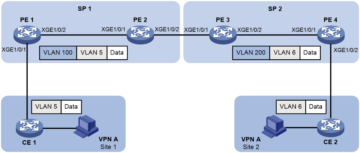
As shown in Figure 11:
· Two VPN A branches, Site 1 and Site 2, are in VLAN 5 and VLAN 6, respectively.
· The two sites use different VPN access services from different service providers, SP 1 and SP 2.
· SP 1 assigns VLAN 100 to Site 1 and Site 2. SP 2 assigns VLAN 200 to Site 1 and Site 2.
Configure one-to-two VLAN mappings and two-to-two VLAN mappings to enable the two branches to communicate across networks SP 1 and SP 2.
Procedure
1. Configure PE 1:
# Create VLANs 5 and 100.
<PE1> system-view
[PE1] vlan 5
[PE1-vlan5] quit
[PE1] vlan 100
[PE1-vlan100] quit
# Configure a one-to-two VLAN mapping on the customer-side port (Ten-GigabitEthernet 1/0/1) to add SVLAN tag 100 to packets from VLAN 5.
[PE1] interface ten-gigabitethernet 1/0/1
[PE1-Ten-GigabitEthernet1/0/1] vlan mapping nest single 5 nested-vlan 100
# Configure Ten-GigabitEthernet 1/0/1 as a hybrid port.
[PE1-Ten-GigabitEthernet1/0/1] port link-type hybrid
# Assign Ten-GigabitEthernet 1/0/1 to VLAN 100 as an untagged member.
[PE1-Ten-GigabitEthernet1/0/1] port hybrid vlan 100 untagged
[PE1-Ten-GigabitEthernet1/0/1] quit
# Configure the network-side port (Ten-GigabitEthernet 1/0/2) as a trunk port.
[PE1] interface ten-gigabitethernet 1/0/2
[PE1-Ten-GigabitEthernet1/0/2] port link-type trunk
# Assign Ten-GigabitEthernet 1/0/2 to VLAN 100.
[PE1-Ten-GigabitEthernet1/0/2] port trunk permit vlan 100
[PE1-Ten-GigabitEthernet1/0/2] quit
2. Configure PE 2:
# Create VLAN 100.
<PE2> system-view
[PE2] vlan 100
[PE2-vlan100] quit
# Configure Ten-GigabitEthernet 1/0/1 as a trunk port.
[PE2] interface ten-gigabitethernet 1/0/1
[PE2-Ten-GigabitEthernet1/0/1] port link-type trunk
# Assign Ten-GigabitEthernet 1/0/1 to VLAN 100.
[PE2-Ten-GigabitEthernet1/0/1] port trunk permit vlan 100
[PE2-Ten-GigabitEthernet1/0/1] quit
# Configure Ten-GigabitEthernet 1/0/2 as a trunk port.
[PE2] interface ten-gigabitethernet 1/0/2
[PE2-Ten-GigabitEthernet1/0/2] port link-type trunk
# Assign Ten-GigabitEthernet 1/0/2 to VLAN 100.
[PE2-Ten-GigabitEthernet1/0/2] port trunk permit vlan 100
[PE2-Ten-GigabitEthernet1/0/2] quit
3. Configure PE 3:
# Create VLANs 5, 6, 100, and 200.
<PE3> system-view
[PE3] vlan 5 to 6
[PE3] vlan 100
[PE3-vlan100] quit
[PE3] vlan 200
[PE3-vlan200] quit
# Configure Ten-GigabitEthernet 1/0/1 as a trunk port.
[PE3] interface ten-gigabitethernet 1/0/1
[PE3-Ten-GigabitEthernet1/0/1] port link-type trunk
# Assign Ten-GigabitEthernet 1/0/1 to VLANs 100 and 200.
[PE3-Ten-GigabitEthernet1/0/1] port trunk permit vlan 100 200
# Configure a two-to-two VLAN mapping on Ten-GigabitEthernet 1/0/1 to map SVLAN 100 and CVLAN 5 to SVLAN 200 and CVLAN 6.
[PE3-Ten-GigabitEthernet1/0/1] vlan mapping tunnel 100 5 translated-vlan 200 6
[PE3-Ten-GigabitEthernet1/0/1] quit
# Configure Ten-GigabitEthernet 1/0/2 as a trunk port.
[PE3] interface ten-gigabitethernet 1/0/2
[PE3-Ten-GigabitEthernet1/0/2] port link-type trunk
# Assign Ten-GigabitEthernet 1/0/2 to VLAN 200.
[PE3-Ten-GigabitEthernet1/0/2] port trunk permit vlan 200
[PE3-Ten-GigabitEthernet1/0/2] quit
4. Configure PE 4:
# Create VLANs 6 and 200.
<PE4> system-view
[PE4] vlan 6
[PE4-vlan6] quit
[PE4] vlan 200
[PE4-vlan200] quit
# Configure the network-side port (Ten-GigabitEthernet 1/0/1) as a trunk port.
[PE4] interface ten-gigabitethernet 1/0/1
[PE4-Ten-GigabitEthernet1/0/1] port link-type trunk
# Assign Ten-GigabitEthernet 1/0/1 to VLAN 200.
[PE4-Ten-GigabitEthernet1/0/1] port trunk permit vlan 200
[PE4-Ten-GigabitEthernet1/0/1] quit
# Configure the customer-side port (Ten-GigabitEthernet 1/0/2) as a hybrid port.
[PE4] interface ten-gigabitethernet 1/0/2
[PE4-Ten-GigabitEthernet1/0/2] port link-type hybrid
# Assign Ten-GigabitEthernet 1/0/2 to VLAN 200 as an untagged member.
[PE4-Ten-GigabitEthernet1/0/2] port hybrid vlan 200 untagged
# Configure a one-to-two VLAN mapping on Ten-GigabitEthernet 1/0/2 to add SVLAN tag 200 to packets from VLAN 6.
[PE4-Ten-GigabitEthernet1/0/2] vlan mapping nest single 6 nested-vlan 200
[PE4-Ten-GigabitEthernet1/0/2] quit
Verifying the configuration
# Verify VLAN mapping information on PE 1.
[PE1] display vlan mapping
Interface Ten-GigabitEthernet1/0/1:
Outer VLAN Inner VLAN Translated Outer VLAN Translated Inner VLAN
5 N/A 100 5
# Verify VLAN mapping information on PE 3.
[PE3] display vlan mapping
Interface Ten-GigabitEthernet1/0/1:
Outer VLAN Inner VLAN Translated Outer VLAN Translated Inner VLAN
100 5 200 6
# Verify VLAN mapping information on PE 4.
[PE4] display vlan mapping
Interface Ten-GigabitEthernet1/0/2:
Outer VLAN Inner VLAN Translated Outer VLAN Translated Inner VLAN
6 N/A 200 6
