- Table of Contents
-
- 05-Layer 3—IP Routing Configuration Guide
- 00-Preface
- 01-Basic IP routing configuration
- 02-Static routing configuration
- 03-RIP configuration
- 04-OSPF configuration
- 05-IS-IS configuration
- 06-BGP configuration
- 07-Policy-based routing configuration
- 08-IPv6 static routing configuration
- 09-RIPng configuration
- 10-OSPFv3 configuration
- 11-IPv6 IS-IS configuration
- 12-IPv6 policy-based routing configuration
- 13-Routing policy configuration
- Related Documents
-
| Title | Size | Download |
|---|---|---|
| 08-IPv6 static routing configuration | 131.81 KB |
Configuring IPv6 static routing
Configuring an IPv6 static route
Configuring BFD for IPv6 static routes
Displaying and maintaining IPv6 static routes
IPv6 static routing configuration examples
Basic IPv6 static route configuration example
BFD for IPv6 static routes configuration example (direct next hop)
BFD for IPv6 static routes configuration example (indirect next hop)
Configuring an IPv6 default route
Configuring IPv6 static routing
Static routes are manually configured and cannot adapt to network topology changes. If a fault or a topological change occurs in the network, the network administrator must modify the static routes manually. IPv6 static routing works well in a simple IPv6 network.
Configuring an IPv6 static route
Before you configure an IPv6 static route, complete the following tasks:
· Configure parameters for the related interfaces.
· Configure link layer attributes for the related interfaces.
· Make sure the neighboring nodes can reach each other.
To configure an IPv6 static route:
|
Step |
Command |
Remarks |
|
1. Enter system view. |
system-view |
N/A |
|
2. Configure an IPv6 static route. |
· Method 1: · Method 2: |
By default, no IPv6 static route is configured. |
|
3. (Optional.) Set the default preference for IPv6 static routes. |
ipv6 route-static default-preference default-preference |
The default setting is 60. |
|
4. (Optional.) Delete all IPv6 static routes, including the default route. |
delete ipv6 [ vpn-instance vpn-instance-name ] static-routes all |
The undo ipv6 route-static command deletes one IPv6 static route. |
Configuring BFD for IPv6 static routes
BFD provides a general purpose, standard, and medium- and protocol-independent fast failure detection mechanism. It can uniformly and quickly detect the failures of the bidirectional forwarding paths between two routers for protocols, such as routing protocols. For more information about BFD, see High Availability Configuration Guide.
|
|
IMPORTANT: Enabling BFD for a flapping route could worsen the situation. |
Bidirectional control mode
To use BFD bidirectional control detection between two devices, enable BFD control mode for each device's static route destined to the peer.
To configure a static route and enable BFD control mode, use one of the following methods:
· Specify an output interface and a direct next hop.
· Specify an indirect next hop and a BFD packet source address for the static route.
To configure BFD control mode for an IPv6 static route (direct next hop):
|
Step |
Command |
Remarks |
|
1. Enter system view. |
system-view |
N/A |
|
2. Configure BFD control mode for an IPv6 static route. |
ipv6 route-static [ vpn-instance s-vpn-instance-name ] ipv6-address prefix-length interface-type interface-number next-hop-address bfd control-packet [ bfd-source ipv6-address ] [ preference preference ] [ tag tag-value ] [ description text ] |
By default, BFD control mode for an IPv6 static route is not configured. |
To configure BFD control mode for an IPv6 static route (indirect next hop):
|
Step |
Command |
Remarks |
|
1. Enter system view. |
system-view |
N/A |
|
2. Configure BFD control mode for an IPv6 static route. |
ipv6 route-static [ vpn-instance s-vpn-instance-name ] ipv6-address prefix-length [ vpn-instance d-vpn-instance-name ] { next-hop-address bfd control-packet bfd-source ipv6-address } [ preference preference ] [ tag tag-value ] [ description text ] |
By default, BFD control mode for an IPv6 static route is not configured. |
Single-hop echo mode
With BFD echo mode enabled for a static route, the output interface sends BFD echo packets to the destination device, which loops the packets back to test the link reachability.
|
|
IMPORTANT: Do not use BFD for a static route with the output interface in spoofing state. |
To configure BFD echo mode for an IPv6 static route:
|
Step |
Command |
Remarks |
|
1. Enter system view. |
system-view |
N/A |
|
2. Configure the source address of echo packets. |
bfd echo-source-ipv6 ipv6-address |
By default, the source address of echo packets is not configured. The source address of echo packets must be a global unicast address. For more information about this command, see High Availability Command Reference. |
|
3. Configure BFD echo mode for an IPv6 static route. |
ipv6 route-static [ vpn-instance s-vpn-instance-name ] ipv6-address prefix-length interface-type interface-number next-hop-address bfd echo-packet [ bfd-source ipv6-address ] [ preference preference ] [ tag tag-value ] [ description text ] |
By default, BFD echo mode for an IPv6 static route is not configured. The next hop IPv6 address must be a global unicast address. |
Displaying and maintaining IPv6 static routes
Execute display commands in any view.
|
Task |
Command |
|
Display IPv6 static route information. |
display ipv6 routing-table protocol static [ inactive | verbose ] |
|
Display IPv6 static route next hop information. |
display ipv6 route-static nib [ nib-id ] [ verbose ] |
|
Display IPv6 static routing table information. |
display ipv6 route-static routing-table [ vpn-instance vpn-instance-name ] [ ipv6-address prefix-length ] |
IPv6 static routing configuration examples
Basic IPv6 static route configuration example
Network requirements
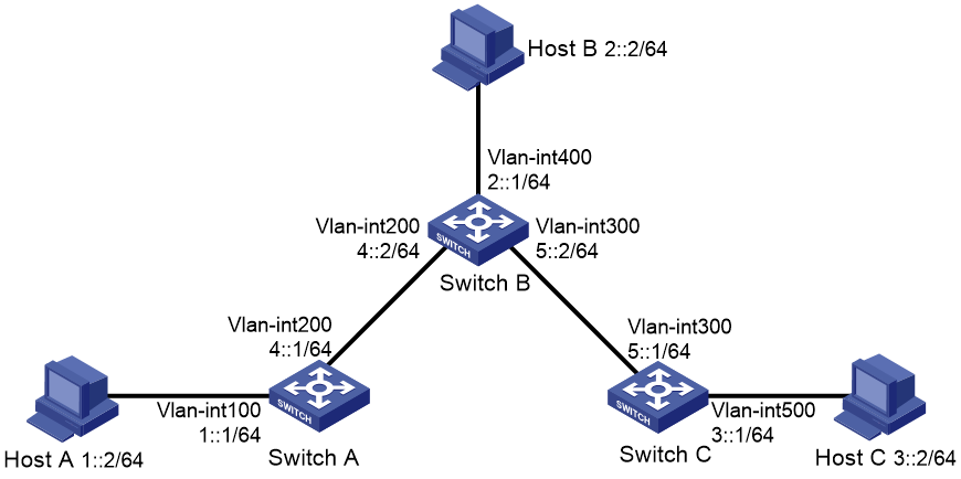
As shown in Figure 1, configure IPv6 static routes so that hosts can reach one another.
Configuration procedure
1. Configure the IPv6 addresses for all VLAN interfaces. (Details not shown.)
2. Configure IPv6 static routes:
# Configure a default IPv6 static route on Switch A.
<SwitchA> system-view
[SwitchA] ipv6 route-static :: 0 4::2
# Configure two IPv6 static routes on Switch B.
<SwitchB> system-view
[SwitchB] ipv6 route-static 1:: 64 4::1
[SwitchB] ipv6 route-static 3:: 64 5::1
# Configure a default IPv6 static route on Switch C.
<SwitchC> system-view
[SwitchC] ipv6 route-static :: 0 5::2
3. Configure the IPv6 addresses for all the hosts and configure the default gateway of Host A, Host B, and Host C as 1::1, 2::1, and 3::1.
Verifying the configuration
# Display the IPv6 static route information on Switch A.
[SwitchA] display ipv6 routing-table protocol static
Summary Count : 1
Static Routing table Status : <Active>
Summary Count : 1
Destination: :: Protocol : Static
NextHop : 4::2 Preference: 60
Interface : Vlan-interface200 Cost : 0
Static Routing table Status : <Inactive>
Summary Count : 0
# Display the IPv6 static route information on Switch B.
[SwitchB] display ipv6 routing-table protocol static
Summary Count : 2
Static Routing table Status : <Active>
Summary Count : 2
Destination: 1::/64 Protocol : Static
NextHop : 4::1 Preference: 60
Interface : Vlan-interface200 Cost : 0
Destination: 3::/64 Protocol : Static
NextHop : 5::1 Preference: 60
Interface : Vlan-interface300 Cost : 0
Static Routing table Status : <Inactive>
Summary Count : 0
# Use the ping command to test the reachability.
[SwitchA] ping ipv6 3::1
Ping6(56 data bytes) 4::1 --> 3::1, press CTRL_C to break
56 bytes from 3::1, icmp_seq=0 hlim=62 time=0.700 ms
56 bytes from 3::1, icmp_seq=1 hlim=62 time=0.351 ms
56 bytes from 3::1, icmp_seq=2 hlim=62 time=0.338 ms
56 bytes from 3::1, icmp_seq=3 hlim=62 time=0.373 ms
56 bytes from 3::1, icmp_seq=4 hlim=62 time=0.316 ms
--- Ping6 statistics for 3::1 ---
5 packet(s) transmitted, 5 packet(s) received, 0.0% packet loss
round-trip min/avg/max/std-dev = 0.316/0.416/0.700/0.143 ms
BFD for IPv6 static routes configuration example (direct next hop)
Network requirements
As shown in Figure 2:
· Configure an IPv6 static route to subnet 120::/64 on Switch A.
· Configure an IPv6 static route to subnet 121::/64 on Switch B.
· Enable BFD for both routes.
· Configure an IPv6 static route to subnet 120::/64 and an IPv6 static route to subnet 121::/64 on Switch C.
When the link between Switch A and Switch B through the Layer 2 switch fails, BFD can detect the failure immediately, and Switch A and Switch B can communicate through Switch C.
Figure 2 Network diagram
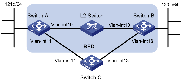
Table 1 Interface and IP address assignment
|
Device |
Interface |
IPv6 address |
|
Switch A |
Vlan-int10 |
12::1/64 |
|
Switch A |
Vlan-int11 |
10::102/64 |
|
Switch B |
Vlan-int10 |
12::2/64 |
|
Switch B |
Vlan-int13 |
13::1/64 |
|
Switch C |
Vlan-int11 |
10::100/64 |
|
Switch C |
Vlan-int13 |
13::2/64 |
Configuration procedure
1. Configure IPv6 addresses for interfaces. (Details not shown.)
2. Configure IPv6 static routes and BFD:
# Configure IPv6 static routes on Switch A and enable BFD control mode for the static route that traverses the Layer 2 switch.
<SwitchA> system-view
[SwitchA] interface vlan-interface 10
[SwitchA-vlan-interface10] bfd min-transmit-interval 500
[SwitchA-vlan-interface10] bfd min-receive-interval 500
[SwitchA-vlan-interface10] bfd detect-multiplier 9
[SwitchA-vlan-interface10] quit
[SwitchA] ipv6 route-static 120:: 64 vlan-interface 10 12::2 bfd control-packet
[SwitchA] ipv6 route-static 120:: 64 10::100 preference 65
[SwitchA] quit
# Configure IPv6 static routes on Switch B and enable BFD control mode for the static route that traverses the Layer 2 switch.
<SwitchB> system-view
[SwitchB] interface vlan-interface 10
[SwitchB-vlan-interface10] bfd min-transmit-interval 500
[SwitchB-vlan-interface10] bfd min-receive-interval 500
[SwitchB-vlan-interface10] bfd detect-multiplier 9
[SwitchB-vlan-interface10] quit
[SwitchB] ipv6 route-static 121:: 64 vlan-interface 10 12::1 bfd control-packet
[SwitchB] ipv6 route-static 121:: 64 vlan-interface 13 13::2 preference 65
[SwitchB] quit
# Configure IPv6 static routes on Switch C.
<SwitchC> system-view
[SwitchC] ipv6 route-static 120:: 64 13::1
[SwitchC] ipv6 route-static 121:: 64 10::102
Verifying the configuration
# Display the BFD sessions on Switch A.
<SwitchA> display bfd session
Total Session Num: 1 Up Session Num: 1 Init Mode: Active
IPv6 Session Working Under Ctrl Mode:
Local Discr: 513 Remote Discr: 33
Source IP: 12::1
Destination IP: 12::2
Session State: Up Interface: Vlan10
Hold Time: 2012ms
The output shows that the BFD session has been created.
# Display IPv6 static routes on Switch A.
<SwitchA> display ipv6 routing-table protocol static
Summary Count : 1
Static Routing table Status : <Active>
Summary Count : 1
Destination: 120::/64 Protocol : Static
NextHop : 12::2 Preference: 60
Interface : Vlan10 Cost : 0
Direct Routing table Status : <Inactive>
Summary Count : 0
The output shows that Switch A communicates with Switch B through VLAN-interface 10. The link over VLAN-interface 10 fails.
# Display IPv6 static routes on Switch A again.
<SwitchA> display ipv6 routing-table protocol static
Summary Count : 1
Static Routing table Status : <Active>
Summary Count : 1
Destination: 120::/64 Protocol : Static
NextHop : 10::100 Preference: 65
Interface : Vlan11 Cost : 0
Static Routing table Status : < Inactive>
Summary Count : 0
The output shows that Switch A communicates with Switch B through VLAN-interface 11.
BFD for IPv6 static routes configuration example (indirect next hop)
Network requirements
As shown in Figure 3:
· Switch A has a route to interface Loopback 1 (2::9/128) on Switch B, and the output interface is VLAN-interface 10.
· Switch B has a route to interface Loopback 1 (1::9/128) on Switch A, and the output interface is VLAN-interface 12.
· Switch D has a route to 1::9/128, and the output interface is VLAN-interface 10. It also has a route to 2::9/128, and the output interface is VLAN-interface 12.
Configure the following:
· Configure an IPv6 static route to subnet 120::/64 on Switch A.
· Configure an IPv6 static route to subnet 121::/64 on Switch B.
· Enable BFD for both routes.
· Configure an IPv6 static route to subnet 120::/64 and an IPv6 static route to subnet 121::/64 on both Switch C and Switch D.
When the link between Switch A and Switch B through Switch D fails, BFD can detect the failure immediately and Switch A and Switch B can communicate through Switch C.
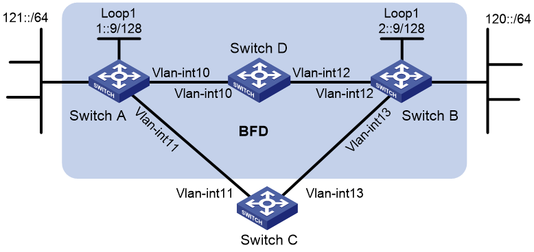
Table 2 Interface and IP address assignment
|
Device |
Interface |
IPv6 address |
|
Switch A |
Vlan-int10 |
12::1/64 |
|
Switch A |
Vlan-int11 |
10::102/64 |
|
Switch A |
Loop1 |
1::9/128 |
|
Switch B |
Vlan-int12 |
11::2/64 |
|
Switch B |
Vlan-int13 |
13::1/64 |
|
Switch B |
Loop1 |
2::9/128 |
|
Switch C |
Vlan-int11 |
10::100/64 |
|
Switch C |
Vlan-int13 |
13::2/64 |
|
Switch D |
Vlan-int10 |
12::2/64 |
|
Switch D |
Vlan-int12 |
11::1/64 |
Configuration procedure
1. Configure IPv6 addresses for interfaces. (Details not shown.)
2. Configure IPv6 static routes and BFD:
# Configure IPv6 static routes on Switch A and enable BFD control packet mode for the IPv6 static route that traverses Switch D.
<SwitchA> system-view
[SwitchA] bfd multi-hop min-transmit-interval 500
[SwitchA] bfd multi-hop min-receive-interval 500
[SwitchA] bfd multi-hop detect-multiplier 9
[SwitchA] ipv6 route-static 120:: 64 2::9 bfd control-packet bfd-source 1::9
[SwitchA] ipv6 route-static 120:: 64 10::100 preference 65
[SwitchA] ipv6 route-static 2::9 128 12::2
[SwitchA] quit
# Configure IPv6 static routes on Switch B and enable BFD control packet mode for the static route that traverses Switch D.
<SwitchB> system-view
[SwitchB] bfd multi-hop min-transmit-interval 500
[SwitchB] bfd multi-hop min-receive-interval 500
[SwitchB] bfd multi-hop detect-multiplier 9
[SwitchB] ipv6 route-static 121:: 64 1::9 bfd control-packet bfd-source 2::9
[SwitchB] ipv6 route-static 121:: 64 13::2 preference 65
[SwitchB] ipv6 route-static 1::9 128 11::1
[SwitchB] quit
# Configure IPv6 static routes on Switch C.
<SwitchC> system-view
[SwitchC] ipv6 route-static 120:: 64 13::1
[SwitchC] ipv6 route-static 121:: 64 10::102
# Configure IPv6 static routes on Switch D.
<SwitchD> system-view
[SwitchD] ipv6 route-static 120:: 64 11::2
[SwitchD] ipv6 route-static 121:: 64 12::1
[SwitchD] ipv6 route-static 2::9 128 11::2
[SwitchD] ipv6 route-static 1::9 128 12::1
Verifying the configuration
# Display the BFD sessions on Switch A.
<SwitchA> display bfd session
Total Session Num: 1 Up Session Num: 1 Init Mode: Active
IPv6 Session Working Under Ctrl Mode:
Local Discr: 513 Remote Discr: 33
Source IP: 1::9
Destination IP: 2::9
Session State: Up Interface: N/A
Hold Time: 2012ms
The output shows that the BFD session has been created.
# Display the IPv6 static routes on Switch A.
<SwitchA> display ipv6 routing-table protocol static
Summary Count : 1
Static Routing table Status : <Active>
Summary Count : 1
Destination: 120::/64 Protocol : Static
NextHop : 2::9 Preference: 60
Interface : Vlan10 Cost : 0
Static Routing table Status : <Inactive>
Summary Count : 0
The output shows that Switch A communicates Switch B through VLAN-interface 10. The link over VLAN-interface 10 fails.
# Display IPv6 static routes on Switch A again.
<SwitchA> display ipv6 routing-table protocol static
Summary Count : 1
Static Routing table Status : <Active>
Summary Count : 1
Destination: 120::/64 Protocol : Static
NextHop : 10::100 Preference: 65
Interface : Vlan11 Cost : 0
Static Routing table Status : <Inactive>
Summary Count : 0
The output shows that Switch A communicates with Switch B through VLAN-interface 11.
Configuring an IPv6 default route
A default IPv6 route is used to forward packets that match no entry in the routing table.
A default IPv6 route can be configured in either of the following ways:
· The network administrator can configure a default route with a destination prefix of ::/0. For more information, see "Configuring IPv6 static routing."
· Some dynamic routing protocols can generate a default IPv6 route. For example, an upstream router running OSPFv3 can generate a default IPv6 route and advertise it to other routers. These routers install the default IPv6 route with the next hop being the upstream router. For more information, see the respective chapters on those routing protocols in this configuration guide.