- Table of Contents
-
- 05-Layer 3—IP Routing Configuration Guide
- 00-Preface
- 01-Basic IP routing configuration
- 02-Static routing configuration
- 03-RIP configuration
- 04-OSPF configuration
- 05-IS-IS configuration
- 06-BGP configuration
- 07-Policy-based routing configuration
- 08-IPv6 static routing configuration
- 09-RIPng configuration
- 10-OSPFv3 configuration
- 11-IPv6 IS-IS configuration
- 12-IPv6 policy-based routing configuration
- 13-Routing policy configuration
- Related Documents
-
| Title | Size | Download |
|---|---|---|
| 06-BGP configuration | 1.63 MB |
Settlements for problems in large-scale BGP networks
Specifying the source address of TCP connections
Controlling route distribution and reception
Configuring BGP route summarization
Advertising optimal routes in the IP routing table
Advertising a default route to a peer or peer group
Enabling prioritized advertisement of default-route withdrawal messages
Limiting routes received from a peer or peer group
Configuring BGP route filtering policies
Setting the BGP route sending rate
Configuring BGP route update delay
Configuring a startup policy for BGP route updates
Configuring BGP route dampening
Controlling BGP path selection
Setting a preferred value for routes received
Configuring preferences for BGP routes
Configuring the default local preference
Configuring the NEXT_HOP attribute
Configuring the AS_PATH attribute
Ignoring IGP metrics during optimal route selection
Tuning and optimizing BGP networks
Configuring the keepalive interval and hold time
Setting the session retry timer
Configuring the interval for sending updates for the same route
Enabling BGP to establish an EBGP session over multiple hops
Enabling immediate re-establishment of direct EBGP connections upon link failure
Enabling 4-byte AS number suppression
Enabling MD5 authentication for BGP peers
Enabling keychain authentication for BGP peers
Configuring BGP load balancing
Configuring the BGP additional path feature
Configuring IPsec for IPv6 BGP
Disabling BGP session establishment
Protecting an EBGP peer when memory usage reaches level 2 threshold
Configuring an update delay for local MPLS labels
Flushing the suboptimal BGP route to the RIB
Setting a DSCP value for outgoing BGP packets
Disabling route recursion policy control for routes received from a peer or peer group
Specifying a label allocation mode
Disabling optimal route selection for labeled routes without tunnel information
Configuring a large-scale BGP network
Configuring BGP route reflection
Configuring a BGP confederation
Enabling SNMP notifications for BGP
Enabling logging for session state changes
Enabling logging for BGP route flapping
Configuring optional 6PE capabilities
Configuring BGP LS route reflection
Specifying an AS number and a router ID for BGP LS messages
Displaying and maintaining BGP
IPv4 BGP configuration examples
Basic BGP configuration example
BGP and IGP route redistribution configuration example
BGP route summarization configuration example
BGP load balancing configuration example
BGP additional path configuration example
BGP community configuration example
BGP route reflector configuration example
BGP confederation configuration example
BGP path selection configuration example
BFD for BGP configuration example
Multicast BGP configuration example
Dynamic BGP peer configuration example
IPv6 BGP configuration examples
IPv6 BGP basic configuration example
IPv6 BGP route reflector configuration example
BFD for IPv6 BGP configuration example
IPsec for IPv6 BGP packets configuration example
IPv6 BGP FRR configuration example
IPv6 multicast BGP configuration example
Configuring BGP
Overview
Border Gateway Protocol (BGP) is an exterior gateway protocol (EGP). It is called internal BGP (IBGP) when it runs within an AS and called external BGP (EBGP) when it runs between ASs.
The current version in use is BGP-4 (RFC 4271).
BGP has the following characteristics:
· Focuses on route control and selection rather than route discovery and calculation.
· Uses TCP to enhance reliability.
· Measures the distance of a route by using a list of ASs that the route must travel through to reach the destination. BGP is also called a path-vector protocol.
· Supports CIDR.
· Reduces bandwidth consumption by advertising only incremental updates. BGP is very suitable to advertise large numbers of routes on the Internet.
· Eliminates routing loops by adding AS path information to BGP route updates.
· Uses policies to implement flexible route filtering and selection.
· Has good scalability.
BGP speaker and BGP peer
A router running BGP is a BGP speaker. A BGP speaker establishes peer relationships with other BGP speakers to exchange routing information over TCP connections.
BGP peers include the following types:
· IBGP peers—Reside in the same AS as the local router.
· EBGP peers—Reside in different ASs from the local router.
BGP message types
BGP uses the following message types:
· Open—After establishing a TCP connection, BGP sends an Open message to establish a session to the peer.
· Update—BGP sends update messages to exchange routing information between peers. Each update message can advertise a group of feasible routes with identical attributes and multiple withdrawn routes.
· Keepalive—BGP sends Keepalive messages between peers to maintain connectivity.
· Route-refresh—BGP sends a Route-refresh message to request the routing information for a specific address family from a peer.
· Notification—BGP sends a Notification message upon detecting an error and immediately closes the connection.
BGP path attributes
BGP uses the following path attributes in update messages for route filtering and selection:
· ORIGIN
The ORIGIN attribute specifies the origin of BGP routes. This attribute has the following types:
¡ IGP—Has the highest priority. Routes generated in the local AS have the IGP attribute.
¡ EGP—Has the second highest priority. Routes obtained through EGP have the EGP attribute.
¡ INCOMPLETE—Has the lowest priority. The source of routes with this attribute is unknown. Routes redistributed from other routing protocols have the INCOMPLETE attribute.
· AS_PATH
The AS_PATH attribute identifies the ASs through which a route has passed. Before advertising a route to another AS, BGP adds the local AS number into the AS_PATH attribute, so the receiver can determine ASs to route the message back.
The AS_PATH attribute has the following types:
¡ AS_SEQUENCE—Arranges AS numbers in sequence. As shown in Figure 1, the number of the AS closest to the receiver's AS is leftmost.
¡ AS_SET—Arranges AS numbers randomly.
Figure 1 AS_PATH attribute
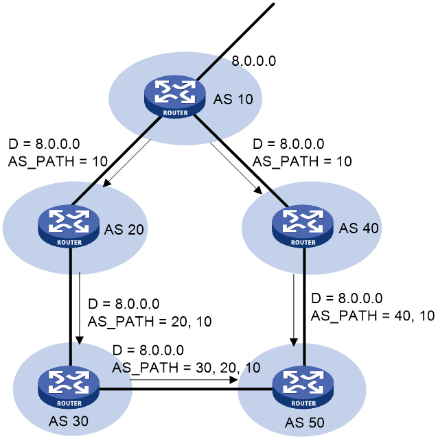
BGP uses the AS_PATH attribute to implement the following functions:
¡ Avoid routing loops—A BGP router does not receive routes containing the local AS number to avoid routing loops.
¡ Affect route selection—BGP gives priority to the route with the shortest AS_PATH length if other factors are the same. As shown in Figure 1, the BGP router in AS 50 gives priority to the route passing AS 40 for sending data to the destination 8.0.0.0. In some applications, you can apply a routing policy to control BGP route selection by modifying the AS_PATH length. For more information about routing policy, see "Configuring routing policies."
¡ Filter routes—By using an AS path list, you can filter routes based on AS numbers contained in the AS_PATH attribute. For more information about AS path list, see "Configuring routing policies."
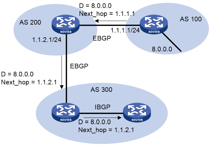
· NEXT_HOP
The NEXT_HOP attribute may not be the IP address of a directly connected router. Its value is determined as follows:
¡ When a BGP speaker advertises a self-originated route to a BGP peer, it sets the address of the sending interface as the NEXT_HOP.
¡ When a BGP speaker sends a received route to an EBGP peer, it sets the address of the sending interface as the NEXT_HOP.
¡ When a BGP speaker sends a route received from an EBGP peer to an IBGP peer, it does not modify the NEXT_HOP attribute. If load balancing is configured, BGP modifies the NEXT_HOP attribute for the equal-cost routes. For load balancing information, see "BGP load balancing."
· MED (MULTI_EXIT_DISC)
BGP advertises the MED attribute between two neighboring ASs, each of which does not advertise the attribute to any other AS.
Similar to metrics used by IGPs, MED is used to determine the optimal route for traffic going into an AS. When a BGP router obtains multiple routes to the same destination but with different next hops, it considers the route with the smallest MED value as the optimal route. As shown in Figure 3, traffic from AS 10 to AS 20 travels through Router B that is selected according to MED.
Figure 3 MED attribute
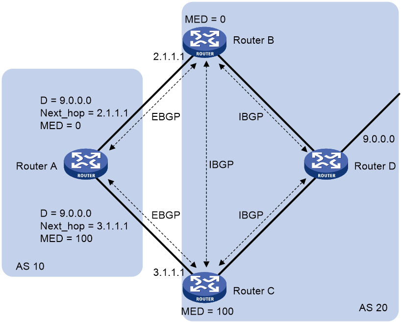
Generally BGP only compares MEDs of routes received from the same AS. You can also use the compare-different-as-med command to force BGP to compare MED values of routes received from different ASs.
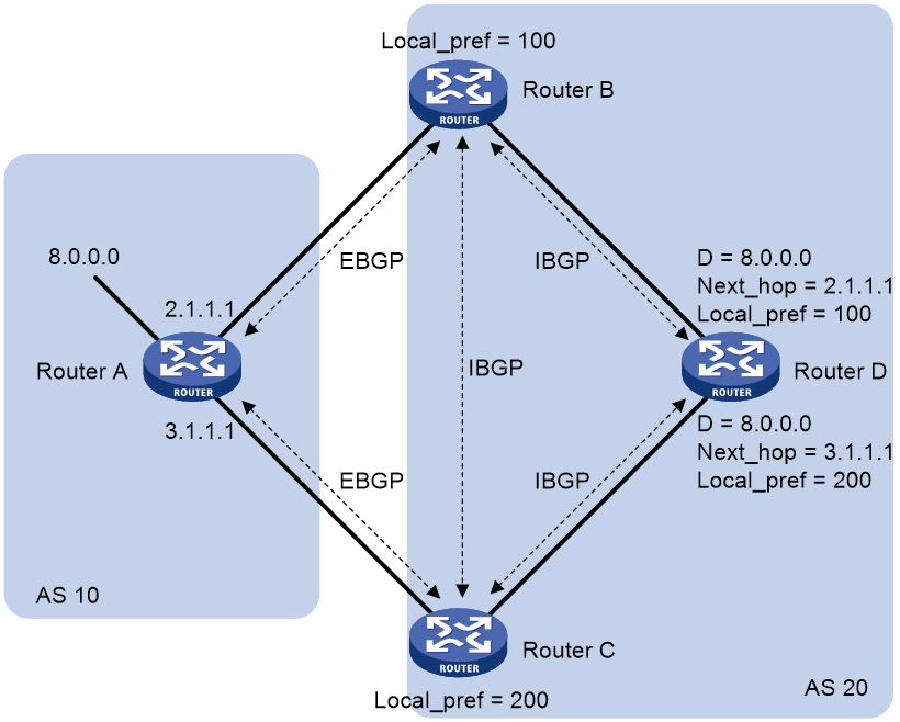
· LOCAL_PREF
The LOCAL_PREF attribute is exchanged between IBGP peers only, and is not advertised to any other AS. It indicates the priority of a BGP router.
BGP uses LOCAL_PREF to determine the optimal route for traffic leaving the local AS. When a BGP router obtains multiple routes to the same destination but with different next hops, it considers the route with the highest LOCAL_PREF value as the optimal route. As shown in Figure 4, traffic from AS 20 to AS 10 travels through Router C that is selected according to LOCAL_PREF.
Figure 4 LOCAL_PREF attribute
· COMMUNITY
The COMMUNITY attribute identifies the community of BGP routes. A BGP community is a group of routes with the same characteristics. It has no geographical boundaries. Routes of different ASs can belong to the same community.
A route can carry one or more COMMUNITY attribute values (each of which is represented by a 4-byte integer). A router uses the COMMUNITY attribute to determine whether to advertise the route and the advertising scope without using complex filters such as ACLs. This mechanism simplifies routing policy configuration, management, and maintenance.
Well-known COMMUNITY attributes involve the following:
¡ INTERNET—By default, all routes belong to the Internet community. Routes with this attribute can be advertised to all BGP peers.
¡ NO_EXPORT—Routes with this attribute cannot be advertised out of the local AS or out of the local confederation, but can be advertised to other sub-ASs in the confederation. For confederation information, see "Settlements for problems in large-scale BGP networks."
¡ No_ADVERTISE—Routes with this attribute cannot be advertised to other BGP peers.
¡ No_EXPORT_SUBCONFED—Routes with this attribute cannot be advertised out of the local AS or other sub-ASs in the local confederation.
You can configure BGP community lists to filter BGP routes based on the BGP COMMUNITY attribute.
· Extended community attribute
To meet new demands, BGP defines the extended community attribute. The extended community attribute has the following advantages over the COMMUNITY attribute:
¡ Provides more attribute values by extending the attribute length to eight bytes.
¡ Allows for using different types of extended community attributes in different scenarios to enhance route filtering and control and simplify configuration and management.
The device supports the route target and Site of Origin (SoO) extended community attributes. For information about route target, see MPLS Configuration Guide.
The SoO attribute specifies the site where the route originated. It prevents advertising a route back to the originating site. If the AS-path attribute is lost, the router can use the SoO attribute to avoid routing loops.
The SoO attribute has the following formats:
¡ 16-bit AS number:32-bit user-defined number. For example, 100:3.
¡ 32-bit IP address:16-bit user-defined number. For example, 192.168.122.15:1.
¡ 32-bit AS number:16-bit user-defined number, where the minimum value of the AS number is 65536. For example, 65536:1.
BGP route selection
BGP discards routes with unreachable NEXT_HOPs. If multiple routes to the same destination are available, BGP selects the optimal route in the following sequence:
1. The route with the highest Preferred_value.
2. The route with the highest LOCAL_PREF.
3. The route generated by the network command, the route redistributed by the import-route command, or the summary route in turn.
4. The route with the shortest AS_PATH.
5. The IGP, EGP, or INCOMPLETE route in turn.
6. The route with the lowest MED value.
7. The route learned from EBGP, confederation EBGP, confederation IBGP, or IBGP in turn.
8. The route with the smallest IGP metric.
9. The route with the smallest recursion depth.
10. If all routes are received from EBGP peers and the peers have different router IDs, the route that used to be an optimal route becomes the optimal route.
11. The route advertised by the router with the smallest router ID.
If one of the routes is advertised by a route reflector, BGP compares the ORIGINATOR_ID of the route with the router IDs of other routers. Then, BGP selects the route with the smallest ID as the optimal route.
12. The route with the shortest CLUSTER_LIST.
13. The route advertised by the peer with the lowest IP address.
The CLUSTER_IDs of route reflectors form a CLUSTER_LIST. If a route reflector receives a route that contains its own CLUSTER ID in the CLUSTER_LIST, the router discards the route to avoid routing loops.
If load balancing is configured, the system selects available routes to implement load balancing.
BGP route advertisement rules
BGP follows these rules for route advertisement:
· When multiple feasible routes to a destination exist, BGP advertises only the optimal route to its peers. If the advertise-rib-active command is configured, BGP advertises the optimal route in the IP routing table. If not, BGP advertises the optimal route in the BGP routing table.
· BGP advertises only routes that it uses.
· BGP advertises routes learned from an EBGP peer to all BGP peers, including both EBGP and IBGP peers.
· BGP advertises routes learned from an IBGP peer to EBGP peers, rather than other IBGP peers.
· After establishing a session to a new BGP peer, BGP advertises all the routes matching the above rules to the peer. After that, BGP advertises only incremental updates to the peer.
BGP load balancing
BGP load balancing is applicable between EBGP peers, between IBGP peers, and between confederations.
BGP implements load balancing through route recursion and route selection.
BGP load balancing through route recursion
The next hop of a BGP route might not be directly connected. One of the reasons is that the next hop information exchanged between IBGP peers is not modified. The BGP router must find the directly connected next hop through IGP. The matching route with the direct next hop is called the recursive route. The process of finding a recursive route is route recursion.
If multiple recursive routes to the same destination are load balanced, BGP generates the same number of next hops to forward packets.
BGP load balancing based on route recursion is always enabled in the system.
BGP load balancing through route selection
IGP routing protocols, such as RIP and OSPF, can use route metrics as criteria to load balance between routes that have the same metric. BGP cannot load balance between routes by route metrics as an IGP protocol does, because BGP does not have a route computation algorithm.
BGP uses the following load balancing criteria to determine load balanced routes:
· The routes have the same ORIGIN, LOCAL_PREF, and MED attributes.
· The routes meet the following requirements on the AS_PATH attribute:
¡ If both the balance as-path-neglect and balance as-path-relax commands are configured or only the balance as-path-neglect command is configured, the routes can have different AS_PATH attributes.
¡ If only the balance as-path-relax command is configured, the routes can have different AS_PATH attributes, but the length of the AS_PATH attributes must be the same.
¡ If neither the balance as-path-neglect nor the balance as-path-relax command is configured, the routes must have the same AS_PATH attribute.
· The routes have the same MPLS label assignment status (labeled or not labeled).
BGP does not use the route selection rules described in "BGP route selection" for load balancing.
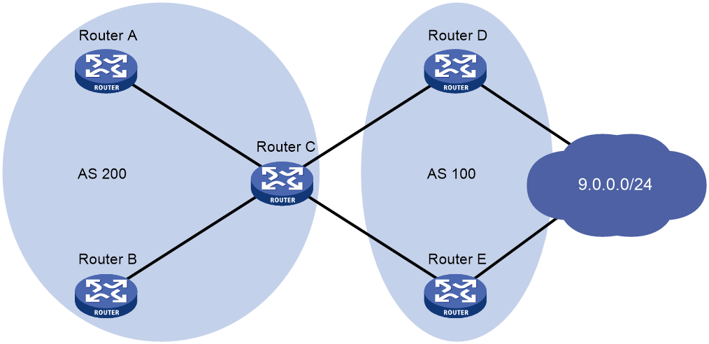
As shown in Figure 5, Router A and Router B are IBGP peers of Router C. Router C allows a maximum number of two ECMP routes for load balancing.
Router D and Router E both advertise a route 9.0.0.0 to Router C. Router C installs the two routes to its routing table for load balancing if the routes meet the BGP load balancing criteria. After that, Router C forwards to Router A and Router B a single route whose attributes are changed as follows:
· AS_PATH attribute:
¡ If the balance as-path-neglect and balance as-path-relax commands are not configured, the AS_PATH attribute does not change.
¡ If the balance as-path-neglect or balance as-path-relax command is configured, the AS_PATH attribute is changed to the attribute of the optimal route.
· The NEXT_HOP attribute is changed to the IP address of Router C.
· Other attributes are changed to be the same as the optimal route.
Settlements for problems in large-scale BGP networks
You can use the following methods to facilitate management and improve route distribution efficiency on a large-scale BGP network.
· Route summarization
Route summarization can reduce the BGP routing table size by advertising summary routes rather than more specific routes.
The system supports both manual and automatic route summarization. Manual route summarization allows you to determine the attribute of a summary route and whether to advertise more specific routes.
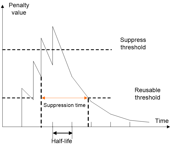
· Route dampening
Route flapping (a route comes up and disappears in the routing table frequently) causes BGP to send many routing updates. It can consume too many resources and affect other operations.
In most cases, BGP runs in complex networks where route changes are more frequent. To solve the problem caused by route flapping, you can use BGP route dampening to suppress unstable routes.
BGP route dampening uses a penalty value to judge the stability of a route. The bigger the value, the less stable the route. Each time a route state changes from reachable to unreachable, or a reachable route's attribute changes, BGP adds a penalty value of 1000 to the route. When the penalty value of the route exceeds the suppress value, the route is suppressed and cannot become the optimal route. When the penalty value reaches the upper limit, no penalty value is added.
If the suppressed route does not flap, its penalty value gradually decreases to half of the suppress value after a period of time. This period is called "Half-life." When the value decreases to the reusable threshold value, the route is usable again.
Figure 6 BGP route dampening
· Peer group
You can organize BGP peers with the same attributes into a group to simplify their configurations.
When a peer joins the peer group, the peer obtains the same configuration as the peer group. If the configuration of the peer group is changed, the configuration of group members is changed.
· Community
You can apply a community list or an extended community list to a routing policy for route control. For more information, see "BGP path attributes."
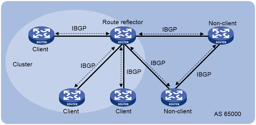
· Route reflector
IBGP peers must be fully meshed to maintain connectivity. If n routers exist in an AS, the number of IBGP connections is n(n-1)/2. If a large number of IBGP peers exist, large amounts of network and CPU resources are consumed to maintain sessions.
Using route reflectors can solve this issue. In an AS, a router acts as a route reflector, and other routers act as clients connecting to the route reflector. The route reflector forwards routing information received from a client to other clients. In this way, all clients can receive routing information from one another without establishing BGP sessions.
A router that is neither a route reflector nor a client is a non-client, which, as shown in Figure 7, must establish BGP sessions to the route reflector and other non-clients.
Figure 7 Network diagram for a route reflector
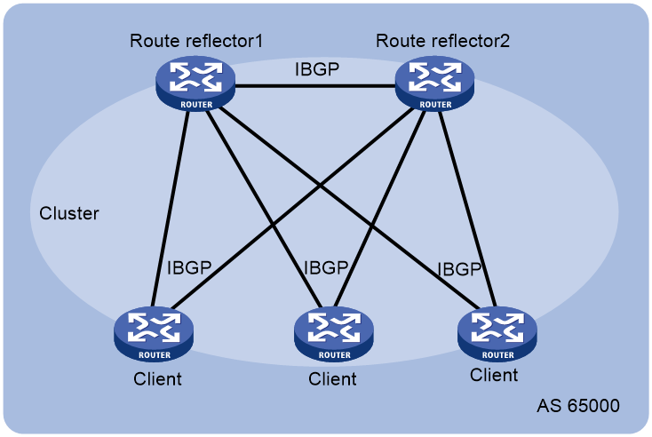
The route reflector and clients form a cluster. Typically a cluster has one route reflector. The ID of the route reflector is the Cluster_ID. You can configure more than one route reflector in a cluster to improve availability, as shown in Figure 8. The configured route reflectors must have the same Cluster_ID to avoid routing loops.
Figure 8 Network diagram for route reflectors
When the BGP routers in an AS are fully meshed, route reflection is unnecessary because it consumes more bandwidth resources. You can use commands to disable route reflection instead of modifying network configuration or changing network topology.
After route reflection is disabled between clients, routes can still be reflected between a client and a non-client.
· Confederation
Confederation is another method to manage growing IBGP connections in an AS. It splits an AS into multiple sub-ASs. In each sub-AS, IBGP peers are fully meshed. As shown in Figure 9, intra-confederation EBGP connections are established between sub-ASs in AS 200.
Figure 9 Confederation network diagram
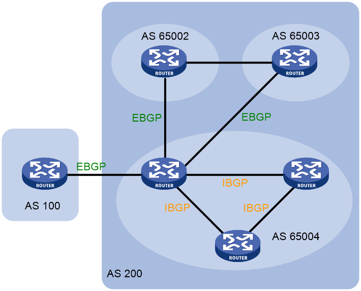
A non-confederation BGP speaker does not need to know sub-ASs in the confederation. It considers the confederation as one AS, and the confederation ID as the AS number. In the above figure, AS 200 is the confederation ID.
Confederation has a deficiency. When you change an AS into a confederation, you must reconfigure the routers, and the topology will be changed.
In large-scale BGP networks, you can use both route reflector and confederation.
MP-BGP
BGP-4 can only advertise IPv4 unicast routing information. Multiprotocol Extensions for BGP-4 (MP-BGP) can advertise routing information for the following address families:
· IPv6 unicast address family.
· IPv4 multicast and IPv6 multicast address families.
PIM uses static and dynamic unicast routes to perform RPF check before creating multicast routing entries. When the multicast and unicast topologies are different, you can use MP-BGP to advertise the routes for RPF check. MP-BGP stores the routes in the BGP multicast routing table. For more information about PIM and RPF check, see IP Multicast Configuration Guide.
· VPNv4 and VPNv6 address families.
For more information about VPNv4 and VPNv6, see MPLS Configuration Guide.
· Labeled IPv4 unicast and IPv6 unicast address families.
MP-BGP advertises IPv4 unicast/IPv6 unicast routes and MPLS labels assigned for the routes. Labeled IPv4 unicast routes apply to inter-AS Option C for MPLS L3VPN. Labeled IPv6 unicast routes apply to 6PE and inter-AS Option C for MPLS L3VPN. For more information about inter-AS Option C, see MPLS Configuration Guide.
· L2VPN address family.
L2VPN information includes label block information and remote peer information. For more information about L2VPN and VPLS, see MPLS Configuration Guide.
· EVPN address family.
MP-BGP advertises EVPN routes to implement automatic VTEP discovery, VXLAN tunnel establishment and assignment, and MAC and ARP information advertisement. For more information about EVPN, see EVPN Configuration Guide.
· IPv4 MDT address family.
MP-BGP advertises MDT information including the PE address and default group so that multicast VPN can create a default MDT that uses the PE as the root on the public network. For more information about multicast VPN, see IP Multicast Configuration Guide.
MP-BGP extended attributes
Prefixes and next hops are key routing information. BGP-4 uses update messages to carry the following information:
· Feasible route prefixes in the Network Layer Reachability Information (NLRI) field.
· Unfeasible route prefixes in the withdrawn routes field.
· Next hops in the NEXT_HOP attribute.
BGP-4 cannot carry routing information for multiple network layer protocols.
To support multiple network layer protocols, MP-BGP defines the following path attributes:
· MP_REACH_NLRI—Carries feasible route prefixes and next hops for multiple network layer protocols.
· MP_UNREACH_NLRI—Carries unfeasible route prefixes for multiple network layer protocols.
MP-BGP uses these two attributes to advertise feasible and unfeasible routes for different network layer protocols. BGP speakers not supporting MP-BGP ignore updates containing these attributes and do not forward them to its peers.
Address family
MP-BGP uses address families and subsequent address families to identify different network layer protocols for routes contained in the MP_REACH_NLRI and MP_UNREACH_NLRI attributes. For example, an Address Family Identifier (AFI) of 2 and a Subsequent Address Family Identifier (SAFI) of 1 identify IPv6 unicast routing information carried in the MP_REACH_NLRI attribute. For address family values, see RFC 1700.
BGP multi-instance
A BGP router can run multiple BGP processes. Each BGP process corresponds to a BGP instance. BGP maintains an independent routing table for each BGP instance.
You can create multiple public address families for a BGP instance. However, each public address family (except for public IPv4 unicast, IPv6 unicast, VPNv4, and VPNv6 address families) can belong to only one BGP instance.
You can create multiple VPN instances for a BGP instance, and each VPN instance can have multiple address families. A VPN instance can belong to only one BGP instance.
Different BGP instances can have the same AS number but cannot have the same name.
BGP configuration views
BGP uses different views to manage routing information for different BGP instances, address families, and VPN instances. Most BGP commands are available in all BGP views. BGP supports multiple VPN instances by establishing a separate routing table for each VPN instance.
Table 1 describes different BGP configuration views.
Table 1 BGP configuration views
|
View names |
Ways to enter the views |
Remarks |
|
BGP instance view |
You can create a BGP instance and enter its view by specifying the instance keyword in the bgp command. Configurations in this view apply to all public address families for the specified BGP instance and all VPN instances (such as confederation, GR, and logging configurations), or apply to all public address families for the specified BGP instance. |
|
|
BGP IPv4 unicast address family view |
Configurations in this view apply to public IPv4 unicast routes and peers of the specified BGP instance. |
|
|
BGP IPv6 unicast address family view |
Configurations in this view apply to public IPv6 unicast routes and peers of the specified BGP instance. |
|
|
BGP IPv4 multicast address family view |
Configurations in this view apply to IPv4 multicast routes and peers of the specified BGP instance. |
|
|
BGP IPv6 multicast address family view |
Configurations in this view apply to IPv6 multicast routes and peers of the specified BGP instance. |
|
|
BGP VPNv4 address family view |
Configurations in this view apply to VPNv4 routes and peers of the specified BGP instance. For more information about BGP VPNv4 address family view, see MPLS Configuration Guide. |
|
|
BGP VPNv6 address family view |
Configurations in this view apply to VPNv6 routes and peers of the specified BGP instance. For more information about BGP VPNv6 address family view, see MPLS Configuration Guide. |
|
|
BGP L2VPN address family view |
Configurations in this view apply to L2VPN information and L2VPN peers of the specified BGP instance. For more information about BGP L2VPN address family view, see MPLS Configuration Guide. |
|
|
BGP EVPN address family view |
Configurations in this view apply to EVPN routes and peers of the specified BGP instance. For more information about BGP EVPN address family view, see EVPN Configuration Guide. |
|
|
BGP-VPN instance view |
Configurations in this view apply to all address families in the specified VPN instance of the specified BGP instance. |
|
|
BGP-VPN IPv4 unicast address family view |
Configurations in this view apply to IPv4 unicast routes and peers in the specified VPN instance of the specified BGP instance. |
|
|
BGP-VPN IPv6 unicast address family view |
Configurations in this view apply to IPv6 unicast routes and peers in the specified VPN instance of the specified BGP instance. |
|
|
BGP-VPN VPNv4 address family view |
Configurations in this view apply to VPNv4 routes and peers in the specified VPN instance of the specified BGP instance. For more information about BGP-VPN VPNv4 address family view, see MPLS Configuration Guide. |
|
|
BGP MDT address family view |
Configurations in this view apply to MDT routes and peers of the specified BGP instance. For more information about BGP MDT address family view, see IP Multicast Configuration Guide. |
|
|
BGP LS address family view |
Configurations in this view apply to LS messages and peers of the specified BGP instance. |
|
|
BGP IPv4 RT filter address family view |
Configurations in this view apply to IPv4 RT filter routes and peers of the specified BGP instance. For more information about BGP IPv4 RT filter address family view, see MPLS Configuration Guide. |
Protocols and standards
· RFC 1700, ASSIGNED NUMBERS
· RFC 1771, A Border Gateway Protocol 4 (BGP-4)
· RFC 1997, BGP Communities Attribute
· RFC 2439, BGP Route Flap Damping
· RFC 2796, BGP Route Reflection
· RFC 2858, Multiprotocol Extensions for BGP-4
· RFC 2918, Route Refresh Capability for BGP-4
· RFC 3065, Autonomous System Confederations for BGP
· RFC 3392, Capabilities Advertisement with BGP-4
· RFC 4271, A Border Gateway Protocol 4 (BGP-4)
· RFC 4360, BGP Extended Communities Attribute
· RFC 4724, Graceful Restart Mechanism for BGP
· RFC 4760, Multiprotocol Extensions for BGP-4
· RFC 5082, The Generalized TTL Security Mechanism (GTSM)
· RFC 6037, Cisco Systems' Solution for Multicast in BGP MPLS IP VPNs
BGP configuration task list
On a basic BGP network, perform the following configuration tasks:
· Enable BGP.
· Configure BGP peers or peer groups. If you configure a BGP setting at both the peer group and the peer level, the most recent configuration takes effect on the peer.
· Control BGP route generation.
To control BGP route distribution and path selection, you must perform additional configuration tasks.
To configure BGP, perform the following tasks (IPv4 unicast/IPv4 multicast):
To configure BGP, perform the following tasks (IPv6 unicast/IPv6 multicast):
Configuring basic BGP
This section describes the basic settings required for a BGP network to run.
Enabling BGP
A router ID is the unique identifier of a BGP router in an AS.
· To ensure the uniqueness of a router ID and enhance availability, specify in BGP instance view the IP address of a local loopback interface as the router ID. Different BGP instances can have the same router ID.
· If no router ID is specified in BGP instance view, the global router ID is used.
· To modify a non-zero router ID of a BGP instance , use the router-id command in BGP instance view, rather than the router id command in system view.
· If you specify a router ID in BGP instance view and then remove the interface that owns the router ID, the router does not select a new router ID. To select a new router ID, use the undo router-id command in BGP instance view.
To enable BGP:
|
Step |
Command |
Remarks |
|
|
1. Enter system view. |
system-view |
N/A |
|
|
2. Configure a global router ID. |
router id router-id |
By default, no global router ID is configured, and BGP uses the highest loopback interface IP address—if any—as the router ID. If no loopback interface IP address is available, BGP uses the highest physical interface IP address as the route ID regardless of the interface status. |
|
|
3. Enable BGP and enter BGP instance view. |
bgp as-number [ instance instance-name ] |
By default, BGP is disabled and no BGP instances exist. |
|
|
4. (Optional.) Configure an SNMP context for the BGP instance. |
snmp context-name context-name |
By default, no SNMP context is configured for a BGP instance. |
|
|
5. (Optional.) Configure a router ID for the BGP instance. |
router-id router-id |
By default, no router ID is configured for a BGP instance, and the BGP instance uses the global router ID configured by the router-id command in system view. |
|
|
6. (Optional.) Enter BGP-VPN instance view. |
ip vpn-instance vpn-instance-name |
The specified VPN instance must have been created and have an RD. For more information about VPN instances, see MPLS Configuration Guide. |
|
|
7. (Optional.) Configure a router ID for the BGP VPN instance. |
router-id { router-id | auto-select } |
By default, no router ID is configured for a BGP VPN instance, and the BGP VPN instance uses the router ID configured in BGP instance view. If no router ID is configured in BGP instance view, the BGP VPN instance uses the global router ID configured in system view. |
|
Configuring a BGP peer
Configuring a BGP peer (IPv4 unicast address family)
|
Step |
Command |
Remarks |
|
8. Enter system view. |
system-view |
N/A |
|
9. Enter BGP instance view or BGP-VPN instance view. |
· Enter BGP instance view: · Enter BGP-VPN instance view: a. bgp as-number [ instance instance-name ] b. ip vpn-instance vpn-instance-name |
N/A |
|
10. Create an IPv4 BGP peer and specify its AS number. |
peer ipv4-address as-number as-number |
By default, no IPv4 BGP peers exist. |
|
11. (Optional.) Configure a description for a peer. |
peer ipv4-address description text |
By default, no description is configured for a peer. |
|
12. Create the BGP IPv4 unicast address family or BGP-VPN IPv4 unicast address family and enter its view. |
address-family ipv4 [ unicast ] |
By default, no BGP IPv4 unicast address family or BGP-VPN IPv4 unicast address family exists. |
|
13. Enable the router to exchange IPv4 unicast routing information with the specified peer. |
peer ipv4-address enable |
By default, the router cannot exchange IPv4 unicast routing information with the peer. |
Configuring a BGP peer (IPv6 unicast address family)
|
Step |
Command |
Remarks |
|
1. Enter system view. |
system-view |
N/A |
|
2. Enter BGP instance view or BGP-VPN instance view. |
· Enter BGP instance view: · Enter BGP-VPN instance view: a. bgp as-number [ instance instance-name ] b. ip vpn-instance vpn-instance-name |
N/A |
|
3. Create an IPv6 BGP peer and specify its AS number. |
peer ipv6-address as-number as-number |
By default, no IPv6 BGP peers exist. |
|
4. (Optional.) Configure a description for a peer. |
peer ipv6-address description text |
By default, no description is configured for a peer. |
|
5. Create the BGP IPv6 unicast address family or BGP-VPN IPv6 unicast address family and enter its view. |
address-family ipv6 [ unicast ] |
By default, no BGP IPv6 unicast address family or BGP-VPN IPv6 unicast address family exists. |
|
6. Enable the router to exchange IPv6 unicast routing information with the specified peer. |
peer ipv6-address enable |
By default, the router cannot exchange IPv6 unicast routing information with the peer. |
Configuring a BGP peer (IPv4 multicast address family)
|
Step |
Command |
Remarks |
|
1. Enter system view. |
system-view |
N/A |
|
2. Enter BGP instance view |
bgp as-number [ instance instance-name ] |
N/A |
|
3. Create an IPv4 BGP peer and specify its AS number. |
peer ipv4-address as-number as-number |
By default, no IPv4 BGP peers exist. |
|
4. (Optional.) Configure a description for the peer. |
peer ipv4-address description text |
By default, no description is configured for a peer. |
|
5. Create the BGP IPv4 multicast address family and enter its view. |
address-family ipv4 multicast |
By default, no BGP IPv4 multicast address family exists. |
|
6. Enable the router to exchange IPv4 unicast routing information used for RPF check with the specified peer. |
peer ipv4-address enable |
By default, the router cannot exchange IPv4 unicast routing information used for RPF check with the peer. |
Configuring a BGP peer (IPv6 multicast address family)
|
Step |
Command |
Remarks |
|
1. Enter system view. |
system-view |
N/A |
|
2. Enter BGP instance view. |
bgp as-number [ instance instance-name ] |
N/A |
|
3. Create an IPv6 BGP peer and specify its AS number. |
peer ipv6-address as-number as-number |
By default, no IPv6 BGP peers exist. |
|
4. (Optional.) Configure a description for the peer. |
peer ipv6-address description text |
By default, no description is configured for a peer. |
|
5. Create the BGP IPv6 multicast address family and enter its view. |
address-family ipv6 multicast |
By default, no BGP IPv6 multicast address family exist. |
|
6. Enable the router to exchange IPv6 unicast routing information used for RPF check with the specified peer. |
peer ipv6-address enable |
By default, the router cannot exchange IPv6 unicast routing information used for RPF check with the peer. |
Configuring dynamic BGP peers
This feature enables BGP to establish dynamic BGP peer relationships with devices in a network. BGP accepts connection requests from the network but it does not initiate connection requests to the network.
After a device in the network initiates a connection request, BGP establishes a dynamic peer relationship with the device.
If multiple BGP peers reside in the same network, you can use this feature to simplify BGP peer configuration.
For a remote device to establish a peer relationship with the local device, you must specify the IP address of the local device on the remote device.
Configuring dynamic BGP peers (IPv4 unicast address family)
|
Step |
Command |
Remarks |
|
1. Enter system view. |
system-view |
N/A |
|
2. Enter BGP instance view or BGP-VPN instance view. |
· Enter BGP instance view: · Enter BGP-VPN instance view: a. bgp as-number [ instance instance-name ] b. ip vpn-instance vpn-instance-name |
N/A |
|
3. Specify devices in a network as dynamic BGP peers and specify an AS number for the peers. |
peer ipv4-address mask-length as-number as-number |
By default, no dynamic BGP peers exist. |
|
4. (Optional.) Configure a description for dynamic BGP peers. |
peer ipv4-address mask-length description text |
By default, no description is configured for dynamic BGP peers. |
|
5. Create the BGP IPv4 unicast address family or BGP-VPN IPv4 unicast address family and enter its view. |
address-family ipv4 [ unicast ] |
By default, no BGP IPv4 unicast address family or BGP-VPN IPv4 unicast address family exists. |
|
6. Enable BGP to exchange IPv4 unicast routing information with dynamic BGP peers in the specified network. |
peer ipv4-address mask-length enable |
By default, BGP cannot exchange IPv4 unicast routing information with dynamic BGP peers. |
Configuring dynamic BGP peers (IPv6 unicast address family)
|
Step |
Command |
Remarks |
|
1. Enter system view. |
system-view |
N/A |
|
2. Enter BGP instance view or BGP-VPN instance view. |
· Enter BGP instance view: · Enter BGP-VPN instance view: a. bgp as-number [ instance instance-name ] b. ip vpn-instance vpn-instance-name |
N/A |
|
3. Specify devices in a network as dynamic BGP peers and specify an AS number for the peers. |
peer ipv6-address prefix-length as-number as-number |
By default, no dynamic BGP peers exist. |
|
4. (Optional.) Configure a description for dynamic BGP peers. |
peer ipv6-address prefix-length description text |
By default, no description is configured for dynamic BGP peers. |
|
5. Create the BGP IPv6 unicast address family or BGP-VPN IPv6 unicast address family and enter its view. |
address-family ipv6 [ unicast ] |
By default, no BGP IPv6 unicast address family or BGP-VPN IPv6 unicast address family exists. |
|
6. Enable BGP to exchange IPv6 unicast routing information with dynamic BGP peers in the specified network. |
peer ipv6-address prefix-length enable |
By default, BGP cannot exchange IPv6 unicast routing information with dynamic BGP peers. |
Configuring dynamic BGP peers (IPv4 multicast address family)
|
Step |
Command |
Remarks |
|
1. Enter system view. |
system-view |
N/A |
|
2. Enter BGP instance view. |
bgp as-number [ instance instance-name ] |
N/A |
|
3. Specify devices in a network as dynamic BGP peers and specify an AS number for the peers. |
peer ipv4-address mask-length as-number as-number |
By default, no dynamic BGP peers exist. |
|
4. (Optional.) Configure a description for dynamic BGP peers. |
peer ipv4-address mask-length description text |
By default, no description is configured for dynamic BGP peers. |
|
5. Create the BGP IPv4 multicast address family and enter its view. |
address-family ipv4 multicast |
By default, no BGP IPv4 multicast address family exists. |
|
6. Enable BGP to exchange IPv4 unicast routing information used for RPF check with dynamic BGP peers in the specified network. |
peer ipv4-address mask-length enable |
By default, BGP cannot exchange IPv4 unicast routing information used for RPF check with dynamic BGP peers. |
Configuring dynamic BGP peers (IPv6 multicast address family)
|
Step |
Command |
Remarks |
|
|
1. Enter system view. |
system-view |
N/A |
|
|
2. Enter BGP instance view. |
bgp as-number [ instance instance-name ] |
N/A |
|
|
3. Specify devices in a network as dynamic BGP peers and specify an AS number for the peers. |
peer ipv6-address prefix-length as-number as-number |
By default, no dynamic BGP peers exist. |
|
|
4. (Optional.) Configure a description for dynamic BGP peers. |
peer ipv6-address prefix-length description text |
By default, no description is configured for dynamic BGP peers. |
|
|
5. Create the BGP IPv6 multicast address family and enter its view. |
address-family ipv6 multicast |
By default, no BGP IPv6 multicast address family exists. |
|
|
6. Enable BGP to exchange IPv6 unicast routing information used for RPF check with dynamic BGP peers in the specified network. |
peer ipv6-address prefix-length enable |
By default, BGP cannot exchange IPv6 unicast routing information used for RPF check with dynamic BGP peers. |
|
Configuring a BGP peer group
The peers in a peer group use the same route selection policy.
In a large-scale network, many peers can use the same route selection policy. You can configure a peer group and add these peers into this group. When you change the policy for the group, the modification also applies to the peers in the group.
A peer group is an IBGP peer group if peers in it belong to the local AS, and is an EBGP peer group if peers in it belong to different ASs.
Configuring an IBGP peer group
After you create an IBGP peer group and then add a peer into it, the system creates the peer in BGP instance view and specifies the local AS number for the peer.
To configure an IBGP peer group (IPv4 unicast address family):
|
Step |
Command |
Remarks |
|
1. Enter system view. |
system-view |
N/A |
|
2. Enter BGP instance view or BGP-VPN instance view. |
· Enter BGP instance view: · Enter BGP-VPN instance view: a. bgp as-number [ instance instance-name ] b. ip vpn-instance vpn-instance-name |
N/A |
|
3. Create an IBGP peer group. |
group group-name [ internal ] |
By default, no IBGP peer groups exist. |
|
4. Add a peer into the IBGP peer group. |
peer ipv4-address [ mask-length ] group group-name [ as-number as-number ] |
By default, no peer exists in the peer group. The as-number as-number option must specify the local AS number. |
|
5. (Optional.) Configure a description for the peer group. |
peer group-name description text |
By default, no description is configured for the peer group. |
|
6. Create the BGP IPv4 unicast address family or BGP-VPN IPv4 unicast address family and enter its view. |
address-family ipv4 [ unicast ] |
By default, no BGP IPv4 unicast address family or BGP-VPN IPv4 unicast address family exists. |
|
7. Enable the router to exchange IPv4 unicast routing information with peers in the specified peer group. |
peer group-name enable |
By default, the router cannot exchange IPv4 unicast routing information with the peers. |
To configure an IBGP peer group (IPv6 unicast address family):
|
Step |
Command |
Remarks |
|
1. Enter system view. |
system-view |
N/A |
|
2. Enter BGP instance view or BGP-VPN instance view. |
· Enter BGP instance view: · Enter BGP-VPN instance view: a. bgp as-number [ instance instance-name ] b. ip vpn-instance vpn-instance-name |
N/A |
|
3. Create an IBGP peer group. |
group group-name [ internal ] |
By default, no IBGP peer groups exist. |
|
4. Add a peer into the IBGP peer group. |
peer ipv6-address [ prefix-length ] group group-name [ as-number as-number ] |
By default, no peer exists in the peer group. The as-number as-number option must specify the local AS number. |
|
5. (Optional.) Configure a description for the peer group. |
peer group-name description text |
By default, no description is configured for the peer group. |
|
6. Create the BGP IPv6 unicast address family or BGP-VPN IPv6 unicast address family and enter its view. |
address-family ipv6 [ unicast ] |
By default, no BGP IPv6 unicast address family or BGP-VPN IPv6 unicast address family exists. |
|
7. Enable the router to exchange IPv6 unicast routing information with peers in the specified peer group. |
peer group-name enable |
By default, the router cannot exchange IPv6 unicast routing information with the peers. |
To configure an IBGP peer group (IPv4 multicast address family):
|
Step |
Command |
Remarks |
|
1. Enter system view. |
system-view |
N/A |
|
2. Enter BGP instance view. |
bgp as-number [ instance instance-name ] |
N/A |
|
3. Create an IBGP peer group. |
group group-name [ internal ] |
By default, no IBGP peer groups exist. |
|
4. Add an IPv4 peer into the IBGP peer group. |
peer ipv4-address [ mask-length ] group group-name [ as-number as-number ] |
By default, no peer exists in the peer group. The as-number as-number option must specify the local AS number. |
|
5. (Optional.) Configure a description for the peer group. |
peer group-name description text |
By default, no description is configured for the peer group. |
|
6. Create the BGP IPv4 multicast address family and enter its view. |
address-family ipv4 multicast |
By default, no BGP IPv4 multicast address family exists. |
|
7. Enable the router to exchange IPv4 unicast routing information used for RPF check with peers in the specified peer group. |
peer group-name enable |
By default, the router cannot exchange IPv4 unicast routing information used for RPF check with the peers in the peer group. |
To configure an IBGP peer group (IPv6 multicast address family):
|
Step |
Command |
Remarks |
|
1. Enter system view. |
system-view |
N/A |
|
2. Enter BGP instance view. |
bgp as-number [ instance instance-name ] |
N/A |
|
3. Create an IBGP peer group. |
group group-name [ internal ] |
By default, no IBGP peer groups exist. |
|
4. Add a peer into the IBGP peer group. |
peer ipv6-address [ prefix-length ] group group-name [ as-number as-number ] |
By default, no peer exists in the peer group. The as-number as-number option must specify the local AS number. |
|
5. (Optional.) Configure a description for the peer group. |
peer group-name description text |
By default, no description is configured for the peer group. |
|
6. Create the BGP IPv6 multicast address family and enter its view. |
address-family ipv6 multicast |
By default, no BGP IPv6 multicast address family exists. |
|
7. Enable the router to exchange IPv6 unicast routing information used for RPF check with peers in the specified peer group. |
peer group-name enable |
By default, the router cannot exchange IPv6 unicast routing information used for RPF check with the peers in the peer group. |
Configuring an EBGP peer group
If peers in an EBGP group belong to the same external AS, the EBGP peer group is a pure EBGP peer group. If not, it is a mixed EBGP peer group.
Use one of the following methods to configure an EBGP peer group:
· Method 1—Create an EBGP peer group, specify its AS number, and add peers into it. All the added peers have the same AS number. All peers in the peer group have the same AS number as the peer group. You can specify an AS number for a peer before adding it into the peer group. The AS number must be the same as that of the peer group.
· Method 2—Create an EBGP peer group, specify an AS number for a peer, and add the peer into the peer group. Peers added in the group can have different AS numbers.
· Method 3—Create an EBGP peer group and add a peer with an AS number into it. Peers added in the group can have different AS numbers.
To configure an EBGP peer group by using Method 1 (IPv4 unicast address family):
|
Step |
Command |
Remarks |
|
1. Enter system view. |
system-view |
N/A |
|
2. Enter BGP instance view or BGP-VPN instance view. |
· Enter BGP instance view: · Enter BGP-VPN instance view: a. bgp as-number [ instance instance-name ] b. ip vpn-instance vpn-instance-name |
N/A |
|
3. Create an EBGP peer group. |
group group-name external |
By default, no EBGP peer groups exist. |
|
4. Specify the AS number of the group. |
peer group-name as-number as-number |
By default, no AS number is specified. If a peer group contains peers, you cannot remove or change its AS number. |
|
5. Add a peer into the EBGP peer group. |
peer ipv4-address [ mask-length ] group group-name [ as-number as-number ] |
By default, no peers exist in the peer group. The as-number as-number option, if used, must specify the same AS number as the peer group-name as-number as-number command. |
|
6. (Optional.) Configure a description for the peer group. |
peer group-name description text |
By default, no description is configured for the peer group. |
|
7. Create the BGP IPv4 unicast address family or BGP-VPN IPv4 unicast address family and enter its view. |
address-family ipv4 [ unicast ] |
By default, no BGP IPv4 unicast address family or BGP-VPN IPv4 unicast address family exists. |
|
8. Enable the router to exchange IPv4 unicast routing information with peers in the specified peer group. |
peer group-name enable |
By default, the router cannot exchange IPv4 unicast routing information with the peers. |
To configure an EBGP peer group by using Method 1 (IPv6 unicast address family):
|
Step |
Command |
Remarks |
|
1. Enter system view. |
system-view |
N/A |
|
2. Enter BGP instance view or BGP-VPN instance view. |
· Enter BGP instance view: · Enter BGP-VPN instance view: a. bgp as-number [ instance instance-name ] b. ip vpn-instance vpn-instance-name |
N/A |
|
3. Create an EBGP peer group. |
group group-name external |
By default, no EBGP peer groups exist. |
|
4. Specify the AS number of the group. |
peer group-name as-number as-number |
By default, no AS number is specified. If a peer group contains peers, you cannot remove or change its AS number. |
|
5. Add a peer into the EBGP peer group. |
peer ipv6-address [ prefix-length ] group group-name [ as-number as-number ] |
By default, no peers exist in the peer group. The as-number as-number option, if used, must specify the same AS number as the peer group-name as-number as-number command. |
|
6. (Optional.) Configure a description for the peer group. |
peer group-name description text |
By default, no description is configured for the peer group. |
|
7. Create the BGP IPv6 unicast address family or BGP-VPN IPv6 unicast address family and enter its view. |
address-family ipv6 [ unicast ] |
By default, no BGP IPv6 unicast address family or BGP-VPN IPv6 unicast address family exists. |
|
8. Enable the router to exchange IPv6 unicast routing information with peers in the specified peer group. |
peer group-name enable |
By default, the router cannot exchange IPv6 unicast routing information with the peers. |
To configure an EBGP peer group by using Method 1 (IPv4 multicast address family):
|
Step |
Command |
Remarks |
|
1. Enter system view. |
system-view |
N/A |
|
2. Enter BGP instance view. |
bgp as-number [ instance instance-name ] |
N/A |
|
3. Create an EBGP peer group. |
group group-name external |
By default, no EBGP peer groups exist. |
|
4. Specify the AS number of the group. |
peer group-name as-number as-number |
By default, no AS number is specified. If a peer group contains peers, you cannot remove or change its AS number. |
|
5. Add an IPv4 BGP peer into the EBGP peer group. |
peer ipv4-address [ mask-length ] group group-name [ as-number as-number ] |
By default, no peers exist in the peer group. The as-number as-number option, if used, must specify the same AS number as the peer group-name as-number as-number command. |
|
6. (Optional.) Configure a description for the peer group. |
peer group-name description text |
By default, no description is configured for the peer group. |
|
7. Create the BGP IPv4 multicast address family and enter its view. |
address-family ipv4 multicast |
By default, no BGP IPv4 multicast address family exists. |
|
8. Enable the router to exchange IPv4 unicast routing information used for RPF check with peers in the specified peer group. |
peer group-name enable |
By default, the router cannot exchange IPv4 unicast routing information used for RPF check with the peers in the group. |
To configure an EBGP peer group by using Method 1 (IPv6 multicast address family):
|
Step |
Command |
Remarks |
|
1. Enter system view. |
system-view |
N/A |
|
2. Enter BGP instance view. |
bgp as-number [ instance instance-name ] |
N/A |
|
3. Create an EBGP peer group. |
group group-name external |
By default, no EBGP peer groups exist. |
|
4. Specify the AS number of the group. |
peer group-name as-number as-number |
By default, no AS number is specified. If a peer group contains peers, you cannot remove or change its AS number. |
|
5. Add an IPv6 BGP peer into the EBGP peer group. |
peer ipv6-address [ prefix-length ] group group-name [ as-number as-number ] |
By default, no peers exist in the peer group. The as-number as-number option, if used, must specify the same AS number as the peer group-name as-number as-number command. |
|
6. (Optional.) Configure a description for the peer group. |
peer group-name description text |
By default, no description is configured for the peer group. |
|
7. Create the BGP IPv6 multicast address family and enter its view. |
address-family ipv6 multicast |
By default, no BGP IPv6 multicast address family exists. |
|
8. Enable the router to exchange IPv6 unicast routing information used for RPF check with peers in the specified peer group. |
peer group-name enable |
By default, the router cannot exchange IPv6 unicast routing information used for RPF check with the peers in the group. |
To configure an EBGP peer group by using Method 2 (IPv4 unicast address family):
|
Step |
Command |
Remarks |
|
1. Enter system view. |
system-view |
N/A |
|
2. Enter BGP instance view or BGP-VPN instance view. |
· Enter BGP instance view: · Enter BGP-VPN instance view: a. bgp as-number [ instance instance-name ] b. ip vpn-instance vpn-instance-name |
N/A |
|
3. Create an EBGP peer group. |
group group-name external |
By default, no EBGP peer groups exist. |
|
4. Create an IPv4 BGP peer and specify its AS number. |
peer ipv4-address [ mask-length ] as-number as-number |
By default, no IPv4 BGP peers exist. |
|
5. Add the peer into the EBGP peer group. |
peer ipv4-address [ mask-length ] group group-name [ as-number as-number ] |
By default, no peers exist in the peer group. The as-number as-number option, if used, must specify the same AS number as the peer ipv4-address [ mask-length ] as-number as-number command. |
|
6. (Optional.) Configure a description for the peer group. |
peer group-name description text |
By default, no description is configured for the peer group. |
|
7. Create the BGP IPv4 unicast address family or BGP-VPN IPv4 unicast address family and enter its view. |
address-family ipv4 [ unicast ] |
By default, no BGP IPv4 unicast address family or BGP-VPN IPv4 unicast address family exists. |
|
8. Enable the router to exchange IPv4 unicast routing information with peers in the specified peer group. |
peer group-name enable |
By default, the router cannot exchange IPv4 unicast routing information with the peers. |
To configure an EBGP peer group by using Method 2 (IPv6 unicast address family):
|
Step |
Command |
Remarks |
|
1. Enter system view. |
system-view |
N/A |
|
2. Enter BGP instance view or BGP-VPN instance view. |
· Enter BGP instance view: · Enter BGP-VPN instance view: a. bgp as-number [ instance instance-name ] b. ip vpn-instance vpn-instance-name |
N/A |
|
3. Create an EBGP peer group. |
group group-name external |
By default, no EBGP peer groups exist. |
|
4. Create an IPv6 BGP peer and specify its AS number. |
peer ipv6-address [ prefix-length ] as-number as-number |
By default, no IPv6 BGP peers exist. |
|
5. Add the peer into the EBGP peer group. |
peer ipv6-address [ prefix-length ] group group-name [ as-number as-number ] |
By default, no peers exist in the peer group. The as-number as-number option, if used, must specify the same AS number as the peer ipv4-address [ prefix-length ] as-number as-number command. |
|
6. (Optional.) Configure a description for the peer group. |
peer group-name description text |
By default, no description is configured for the peer group. |
|
7. Create the BGP IPv6 unicast address family or BGP-VPN IPv6 unicast address family and enter its view. |
address-family ipv6 [ unicast ] |
By default, no BGP IPv6 unicast address family or BGP-VPN IPv6 unicast address family exists. |
|
8. Enable the router to exchange IPv6 unicast routing information with peers in the specified peer group. |
peer group-name enable |
By default, the router cannot exchange IPv6 unicast routing information with the peers. |
To configure an EBGP peer group by using Method 2 (IPv4 multicast address family):
|
Step |
Command |
Remarks |
|
1. Enter system view. |
system-view |
N/A |
|
2. Enter BGP instance view. |
bgp as-number [ instance instance-name ] |
N/A |
|
3. Create an EBGP peer group. |
group group-name external |
By default, no EBGP peer groups exist. |
|
4. Create an IPv4 BGP peer and specify its AS number. |
peer ipv4-address [ mask-length ] as-number as-number |
By default, no IPv4 BGP peers exist. |
|
5. Add the peer into the EBGP peer group. |
peer ipv4-address [ mask-length ] group group-name [ as-number as-number ] |
By default, no peers exist in the peer group. The as-number as-number option, if used, must specify the same AS number as the peer ipv4-address [ mask-length ] as-number as-number command. |
|
6. (Optional.) Configure a description for the peer group. |
peer group-name description text |
By default, no description is configured for the peer group. |
|
7. Create the BGP IPv4 multicast address family and enter its view. |
address-family ipv4 multicast |
By default, no BGP IPv4 multicast address family exists. |
|
8. Enable the router to exchange IPv4 unicast routing information used for RPF check with peers in the specified peer group. |
peer group-name enable |
By default, the router cannot exchange IPv4 unicast routing information used for RPF check with the peers in the group. |
To configure an EBGP peer group by using Method 2 (IPv6 multicast address family):
|
Step |
Command |
Remarks |
|
1. Enter system view. |
system-view |
N/A |
|
2. Enter BGP instance view. |
bgp as-number [ instance instance-name ] |
N/A |
|
3. Create an EBGP peer group. |
group group-name external |
By default, no EBGP peer groups exist. |
|
4. Create an IPv6 BGP peer and specify its AS number. |
peer ipv6-address [ prefix-length ] as-number as-number |
By default, no IPv6 BGP peers exist. |
|
5. Add the peer into the EBGP peer group. |
peer ipv6-address [ prefix-length ] group group-name [ as-number as-number ] |
By default, no peers exist in the peer group. The as-number as-number option, if used, must specify the same AS number as the peer ipv6-address [ prefix-length ] as-number as-number command. |
|
6. (Optional.) Configure a description for the peer group. |
peer group-name description text |
By default, no description is configured for the peer group. |
|
7. Create the BGP IPv6 multicast address family and enter its view. |
address-family ipv6 multicast |
By default, no BGP IPv6 multicast address family exists. |
|
8. Enable the router to exchange IPv6 unicast routing information used for RPF check with peers in the specified peer group. |
peer group-name enable |
By default, the router cannot exchange IPv6 unicast routing information used for RPF check with the peers in the group. |
To configure an EBGP peer group by using Method 3 (IPv4 unicast address family):
|
Step |
Command |
Remarks |
|
1. Enter system view. |
system-view |
N/A |
|
2. Enter BGP instance view or BGP-VPN instance view. |
· Enter BGP instance view: · Enter BGP-VPN instance view: a. bgp as-number [ instance instance-name ] b. ip vpn-instance vpn-instance-name |
N/A |
|
3. Create an EBGP peer group. |
group group-name external |
By default, no EBGP peer groups exist. |
|
4. Add a peer into the EBGP peer group. |
peer ipv4-address [ mask-length ] group group-name as-number as-number |
By default, no peers exist in the peer group. |
|
5. (Optional.) Configure a description for the peer group. |
peer group-name description text |
By default, no description is configured for the peer group. |
|
6. Create the BGP IPv4 unicast address family or BGP-VPN IPv4 unicast address family and enter its view. |
address-family ipv4 [ unicast ] |
By default, no BGP IPv4 unicast address family or BGP-VPN IPv4 unicast address family exists. |
|
7. Enable the router to exchange IPv4 unicast routing information with peers in the specified peer group. |
peer group-name enable |
By default, the router cannot exchange IPv4 unicast routing information with the peers. |
To configure an EBGP peer group by using Method 3 (IPv6 unicast address family):
|
Step |
Command |
Remarks |
|
1. Enter system view. |
system-view |
N/A |
|
2. Enter BGP instance view or BGP-VPN instance view. |
· Enter BGP instance view: · Enter BGP-VPN instance view: a. bgp as-number [ instance instance-name ] b. ip vpn-instance vpn-instance-name |
N/A |
|
3. Create an EBGP peer group. |
group group-name external |
By default, no EBGP peer groups exist. |
|
4. Add a peer into the EBGP peer group. |
peer ipv6-address [ prefix-length ] group group-name as-number as-number |
By default, no peers exist in the peer group. |
|
5. (Optional.) Configure a description for the peer group. |
peer group-name description text |
By default, no description is configured for the peer group. |
|
6. Create the BGP IPv6 unicast address family or BGP-VPN IPv6 unicast address family and enter its view. |
address-family ipv6 [ unicast ] |
By default, no BGP IPv6 unicast address family or BGP-VPN IPv6 unicast address family exists. |
|
7. Enable the router to exchange IPv6 unicast routing information with peers in the specified peer group. |
peer group-name enable |
By default, the router cannot exchange IPv6 unicast routing information with the peers. |
To configure an EBGP peer group by using Method 3 (IPv4 multicast address family):
|
Step |
Command |
Remarks |
|
1. Enter system view. |
system-view |
N/A |
|
2. Enter BGP instance view. |
bgp as-number [ instance instance-name ] |
N/A |
|
3. Create an EBGP peer group. |
group group-name external |
By default, no EBGP peer groups exist. |
|
4. Add an IPv4 BGP peer into the EBGP peer group. |
peer ipv4-address [ mask-length ] group group-name as-number as-number |
By default, no peers exist in the peer group. |
|
5. (Optional.) Configure a description for the peer group. |
peer group-name description text |
By default, no description is configured for the peer group. |
|
6. Create the BGP IPv4 multicast address family and enter its view. |
address-family ipv4 multicast |
By default, no BGP IPv4 multicast address family exists. |
|
7. Enable the router to exchange IPv4 unicast routing information used for RPF check with peers in the specified peer group. |
peer group-name enable |
By default, the router cannot exchange IPv4 unicast routing information used for RPF check with the peers. |
To configure an EBGP peer group by using Method 3 (IPv6 multicast address family):
|
Step |
Command |
Remarks |
|
1. Enter system view. |
system-view |
N/A |
|
2. Enter BGP instance view. |
bgp as-number [ instance instance-name ] |
N/A |
|
3. Create an EBGP peer group. |
group group-name external |
By default, no EBGP peer groups exist. |
|
4. Add an IPv6 BGP peer into the EBGP peer group. |
peer ipv6-address [ prefix-length ] group group-name as-number as-number |
By default, no peers exist in the peer group. |
|
5. (Optional.) Configure a description for the peer group. |
peer group-name description text |
By default, no description is configured for the peer group. |
|
6. Create the BGP IPv6 multicast address family and enter its view. |
address-family ipv6 multicast |
By default, no BGP IPv6 multicast address family exists. |
|
7. Enable the router to exchange IPv6 unicast routing information used for RPF check with peers in the specified peer group. |
peer group-name enable |
By default, the router cannot exchange IPv6 unicast routing information used for RPF check with the peers in the group. |
Specifying the source address of TCP connections
This task allows you to specify the source address or source interface for the local router to establish TCP connections to a BGP peer or peer group. This task is applicable to the following scenarios:
· The peer's IPv4/IPv6 address does not belong to the interface directly connected to the local router. To ensure successful TCP connection establishment, use one of the following methods:
¡ Specify the interface to which the IPv4/IPv6 address belongs as the source interface on the peer.
¡ Specify the IPv4/IPv6 address of the interface directly connected to the local router as the source address on the peer.
· On a BGP router that has multiple links to a peer, the source interface for TCP connection changes because the primary source interface fails. To avoid this problem, specify a loopback interface as the source interface or specify the IP address of a loopback interface as the source address.
· You want to establish multiple BGP sessions to a router. In this case, BGP might fail to determine the source address for each TCP connection based on the optimal route to the peer. To prevent this problem, use one of the following methods:
¡ If the BGP sessions use IP addresses of different interfaces, specify a source interface or source address for each session.
¡ If the BGP sessions use different IP addresses of the same interface, specify a source address for each session.
To specify the source address of TCP connections (IPv4 unicast/multicast address family):
|
Step |
Command |
Remarks |
|
1. Enter system view. |
system-view |
N/A |
|
2. Enter BGP instance view or BGP-VPN instance view. |
· Enter BGP instance view: · Enter BGP-VPN instance view: a. bgp as-number [ instance instance-name ] b. ip vpn-instance vpn-instance-name |
N/A |
|
3. Specify the source address or source interface for establishing TCP connections to a peer or peer group. |
· Specify the source address for establishing
TCP connections to a peer or peer group: · Specify the source interface for establishing
TCP connections to a peer or peer group: |
Use either method. By default, BGP uses the primary IPv4 address of the output interface in the optimal route to a peer or peer group as the source address of TCP connections to the peer or peer group. |
To specify the source address of TCP connections (IPv6 unicast/multicast address family):
|
Step |
Command |
Remarks |
|
1. Enter system view. |
system-view |
N/A |
|
2. Enter BGP instance view or BGP-VPN instance view. |
· Enter BGP instance view: · Enter BGP-VPN instance view: a. bgp as-number [ instance instance-name ] b. ip vpn-instance vpn-instance-name |
N/A |
|
3. Specify the source IPv6 address or source interface for establishing TCP connections to a peer or peer group. |
· Specify the source IPv6 address for establishing
TCP connections to a peer or peer group: · Specify the source interface for establishing
TCP connections to a peer or peer group: |
Use either method. By default, BGP uses the IPv6 address of the output interface in the optimal route to the BGP peer or peer group as the source address of TCP connections to the peer or peer group. |
Generating BGP routes
BGP can generate routes in the following ways:
· Advertise local networks.
· Redistribute IGP routes.
Injecting a local network
Perform this task to inject a network in the local routing table to the BGP routing table, so BGP can advertise the network to BGP peers. The ORIGIN attribute of BGP routes advertised in this way is IGP. You can also use a routing policy to control route advertisement.
The specified network must be available and active in the local IP routing table.
To inject a local network (IPv4 unicast/multicast address family):
|
Step |
Command |
Remarks |
|
1. Enter system view. |
system-view |
N/A |
|
2. Enter BGP IPv4 unicast address family view, BGP-VPN IPv4 unicast address family view, or BGP IPv4 multicast address family view. |
· Enter BGP IPv4 unicast address family view: a. bgp as-number [ instance instance-name ] b. address-family ipv4 [ unicast ] · Enter BGP-VPN IPv4 unicast address family view: a. bgp as-number [ instance instance-name ] b. ip vpn-instance vpn-instance-name c. address-family ipv4 [ unicast ] · Enter BGP IPv4 multicast address family view: a. bgp as-number [ instance instance-name ] b. address-family ipv4 multicast |
N/A |
|
3. Configure BGP to advertise a local network. |
network ipv4-address [ mask-length | mask ] [ route-policy route-policy-name ] |
By default, BGP does not advertise local networks. |
To inject a local network (IPv6 unicast/multicast address family):
|
Step |
Command |
Remarks |
|
1. Enter system view. |
system-view |
N/A |
|
2. Enter BGP IPv6 unicast address family view, BGP-VPN IPv6 unicast address family view, or BGP IPv6 multicast address family view. |
· Enter BGP IPv6 unicast address family view: a. bgp as-number [ instance instance-name ] b. address-family ipv6 [ unicast ] · Enter BGP-VPN IPv6 unicast address family view: a. bgp as-number [ instance instance-name ] b. ip vpn-instance vpn-instance-name c. address-family ipv6 [ unicast ] · Enter BGP IPv6 multicast address family view: a. bgp as-number [ instance instance-name ] b. address-family ipv6 multicast |
N/A |
|
3. Configure BGP to advertise a local network. |
network ipv6-address prefix-length [ route-policy route-policy-name ] |
By default, BGP does not advertise local networks. |
Redistributing IGP routes
Perform this task to configure route redistribution from an IGP to BGP.
By default, BGP does not redistribute default IGP routes. You can use the default-route imported command to redistribute default IGP routes into the BGP routing table.
Only active routes can be redistributed. To view route state information, use the display ip routing-table protocol or display ipv6 routing-table protocol command.
The ORIGIN attribute of BGP routes redistributed from IGPs is INCOMPLETE.
To configure BGP to redistribute IGP routes (IPv4 unicast/multicast address family):
|
Step |
Command |
Remarks |
|
1. Enter system view. |
system-view |
N/A |
|
2. Enter BGP IPv4 unicast address family view, BGP-VPN IPv4 unicast address family view, or BGP IPv4 multicast address family view. |
· Enter BGP IPv4 unicast address family view: a. bgp as-number [ instance instance-name ] b. address-family ipv4 [ unicast ] · Enter BGP-VPN IPv4 unicast address family view: a. bgp as-number [ instance instance-name ] b. ip vpn-instance vpn-instance-name c. address-family ipv4 [ unicast ] · Enter BGP IPv4 multicast address family view: a. bgp as-number [ instance instance-name ] b. address-family ipv4 multicast |
N/A |
|
3. Enable route redistribution from the specified IGP into BGP. |
import-route protocol [ { process-id | all-processes } [ allow-direct | med med-value | route-policy route-policy-name ] * ] |
By default, BGP does not redistribute IGP routes. |
|
4. (Optional.) Enable default route redistribution into BGP. |
default-route imported |
By default, BGP does not redistribute default routes. |
To configure BGP to redistribute IGP routes (IPv6 unicast/multicast address family):
|
Step |
Command |
Remarks |
|
1. Enter system view. |
system-view |
N/A |
|
2. Enter BGP IPv6 unicast address family view, BGP-VPN IPv6 unicast address family view, or BGP IPv6 multicast address family view. |
· Enter BGP IPv6 unicast address family view: a. bgp as-number [ instance instance-name ] b. address-family ipv6 [ unicast ] · Enter BGP-VPN IPv6 unicast address family view: a. bgp as-number [ instance instance-name ] b. ip vpn-instance vpn-instance-name c. address-family ipv6 [ unicast ] · Enter BGP IPv6 multicast address family view: a. bgp as-number [ instance instance-name ] b. address-family ipv6 multicast |
N/A |
|
3. Enable route redistribution from the specified IGP into BGP. |
import-route protocol [ { process-id | all-processes } [ allow-direct | med med-value | route-policy route-policy-name ] * ] |
By default, BGP does not redistribute IGP routes. |
|
4. (Optional.) Enable default route redistribution into BGP. |
default-route imported |
By default, BGP does not redistribute default routes. |
Controlling route distribution and reception
This section describes how to control route distribution and reception.
Configuring BGP route summarization
Route summarization can reduce the number of redistributed routes and the routing table size. IPv4 BGP supports automatic route summarization and manual route summarization. Manual summarization takes precedence over automatic summarization. IPv6 BGP supports only manual route summarization.
The output interface of a BGP summary route is Null 0 on the originating router. Therefore, a summary route must not be an optimal route on the originating router. Otherwise, BGP will fail to forward packets matching the route. If a summarized specific route has the same mask as the summary route, but has a lower priority, the summary route becomes the optimal route. To ensure correct packet forwarding, change the priority of the summary or specific route to make the specific route the optimal route.
Configuring automatic route summarization
Automatic route summarization enables BGP to summarize IGP subnet routes redistributed by the import-route command so BGP advertises only natural network routes.
To configure automatic route summarization (IPv4 unicast/multicast address family):
|
Step |
Command |
Remarks |
|
1. Enter system view. |
system-view |
N/A |
|
2. Enter BGP IPv4 unicast address family view, BGP-VPN IPv4 unicast address family view, or BGP IPv4 multicast address family view. |
· Enter BGP IPv4 unicast address family view: a. bgp as-number [ instance instance-name ] b. address-family ipv4 [ unicast ] · Enter BGP-VPN IPv4 unicast address family view: a. bgp as-number [ instance instance-name ] b. ip vpn-instance vpn-instance-name c. address-family ipv4 [ unicast ] · Enter BGP IPv4 multicast address family view: a. bgp as-number [ instance instance-name ] b. address-family ipv4 multicast |
N/A |
|
3. Configure automatic route summarization. |
summary automatic |
By default, automatic route summarization is not configured. |
Configuring manual route summarization
By configuring manual route summarization, you can do the following:
· Summarize both redistributed routes and routes injected using the network command.
· Determine the mask length for a summary route.
To configure BGP manual route summarization (IPv4 unicast/multicast address family):
|
Step |
Command |
Remarks |
|
1. Enter system view. |
system-view |
N/A |
|
2. Enter BGP IPv4 unicast address family view, BGP-VPN IPv4 unicast address family view, or BGP IPv4 multicast address family view. |
· Enter BGP IPv4 unicast address family view: a. bgp as-number [ instance instance-name ] b. address-family ipv4 [ unicast ] · Enter BGP-VPN IPv4 unicast address family view: a. bgp as-number [ instance instance-name ] b. ip vpn-instance vpn-instance-name c. address-family ipv4 [ unicast ] · Enter BGP IPv4 multicast address family view: a. bgp as-number [ instance instance-name ] b. address-family ipv4 multicast |
N/A |
|
3. Create a summary route in the BGP routing table. |
aggregate ipv4-address { mask-length | mask } [ as-set | attribute-policy route-policy-name | detail-suppressed | origin-policy route-policy-name | suppress-policy route-policy-name ] * |
By default, no summary routes are configured. |
To configure BGP manual route summarization (IPv6 unicast/multicast address family):
|
Step |
Command |
Remarks |
|
1. Enter system view. |
system-view |
N/A |
|
2. Enter BGP IPv6 unicast address family view, BGP-VPN IPv6 unicast address family view, or BGP IPv6 multicast address family view. |
· Enter BGP IPv6 unicast address family view: a. bgp as-number [ instance instance-name ] b. address-family ipv6 [ unicast ] · Enter BGP-VPN IPv6 unicast address family view: a. bgp as-number [ instance instance-name ] b. ip vpn-instance vpn-instance-name c. address-family ipv6 [ unicast ] · Enter BGP IPv6 multicast address family view: a. bgp as-number [ instance instance-name ] b. address-family ipv6 multicast |
N/A |
|
3. Create a summary route in the IPv6 BGP routing table. |
aggregate ipv6-address prefix-length [ as-set | attribute-policy route-policy-name | detail-suppressed | origin-policy route-policy-name | suppress-policy route-policy-name ] * |
By default, no summary routes are configured. |
Advertising optimal routes in the IP routing table
By default, BGP advertises optimal routes in the BGP routing table, which may not be optimal in the IP routing table. This task allows you to advertise BGP routes that are optimal in the IP routing table.
To enable BGP to advertise optimal routes in the IP routing table (IPv4 unicast):
|
Step |
Command |
Remarks |
|
1. Enter system view. |
system-view |
N/A |
|
2. Enter BGP instance view. |
bgp as-number [ instance instance-name ] |
N/A |
|
3. Enable BGP to advertise optimal routes in the IP routing table. |
advertise-rib-active |
By default, BGP advertises optimal routes in the BGP routing table. |
|
4. Enter BGP IPv4 unicast address family view or BGP-VPN IPv4 unicast address family view. |
· Enter BGP IPv4 unicast address family view: · Enter BGP-VPN IPv4 unicast address family view: a. ip vpn-instance vpn-instance-name b. address-family ipv4 [ unicast ] |
N/A |
|
5. Enable BGP to advertise optimal routes in the IP routing table of the address family in the VPN instance. |
advertise-rib-active |
By default, the setting is the same as that in BGP instance view. |
To enable BGP to advertise optimal routes in the IPv6 routing table (IPv6 unicast):
|
Step |
Command |
Remarks |
|
1. Enter system view. |
system-view |
N/A |
|
2. Enter BGP instance view. |
bgp as-number [ instance instance-name ] |
N/A |
|
3. Enable BGP to advertise optimal routes in the IPv6 routing table. |
advertise-rib-active |
By default, BGP advertises optimal routes in the BGP routing table. |
|
4. Enter BGP IPv6 unicast address family view or BGP-VPN IPv6 unicast address family view. |
· Enter BGP IPv6 unicast address family view: · Enter BGP-VPN IPv6 unicast address family view: a. ip vpn-instance vpn-instance-name b. address-family ipv6 [ unicast ] |
N/A |
|
5. Enable BGP to advertise optimal routes in the IPv6 routing table of the address family in the VPN instance. |
advertise-rib-active |
By default, the setting is the same as that in BGP instance view. |
Advertising a default route to a peer or peer group
Perform this task to advertise a default BGP route with the next hop being the advertising router to a peer or peer group.
To advertise a default route to a peer or peer group (IPv4 unicast/multicast address family):
|
Command |
Remarks |
|
|
1. Enter system view. |
system-view |
N/A |
|
2. Enter BGP IPv4 unicast address family view, BGP-VPN IPv4 unicast address family view, or BGP IPv4 multicast address family view. |
· Enter BGP IPv4 unicast address family view: a. bgp as-number [ instance instance-name ] b. address-family ipv4 [ unicast ] · Enter BGP-VPN IPv4 unicast address family view: a. bgp as-number [ instance instance-name ] b. ip vpn-instance vpn-instance-name c. address-family ipv4 [ unicast ] · Enter BGP IPv4 multicast address family view: a. bgp as-number [ instance instance-name ] b. address-family ipv4 multicast |
N/A |
|
3. Advertise a default route to a peer or peer group. |
peer { group-name | ipv4-address [ mask-length ] } default-route-advertise [ route-policy route-policy-name ] |
By default, no default route is advertised. |
To advertise a default route to a peer or peer group (IPv6 unicast/multicast address family):
|
Step |
Command |
Remarks |
|
1. Enter system view. |
system-view |
N/A |
|
2. Enter BGP IPv6 unicast address family view, BGP-VPN IPv6 unicast address family view, or BGP IPv6 multicast address family view. |
· Enter BGP IPv6 unicast address family view: a. bgp as-number [ instance instance-name ] b. address-family ipv6 [ unicast ] · Enter BGP-VPN IPv6 unicast address family view: a. bgp as-number [ instance instance-name ] b. ip vpn-instance vpn-instance-name c. address-family ipv6 [ unicast ] · Enter BGP IPv6 multicast address family view: a. bgp as-number [ instance instance-name ] b. address-family ipv6 multicast |
N/A |
|
3. Advertise a default route to a peer or peer group. |
peer { group-name | ipv6-address [ prefix-length ] } default-route-advertise [ route-policy route-policy-name ] |
By default, no default route is advertised. |
Enabling prioritized advertisement of default-route withdrawal messages
Typically a BGP router does not send withdrawal messages of the default route prior to other routes to its peers. If the peer relationship is down, the default route cannot be withdrawn first. Traffic interruption might occur. Perform this task to configure BGP to send the withdrawal message of the default route prior to other routes. This can reduce the traffic interruption time when the peer relationship is down.
As shown in Figure 10, Device A and Device B send a default route and large numbers of external routes to the internal network. After optimal route selection, Device E selects Device A as the egress router to reach the external network. If the peer relationship between Device A and Device C is down, Device C sends route withdrawal messages to Device E. If the withdrawal message of the default route is not sent prior to other routes, traffic forwarded through the default route will be interrupted. After you configure this task, traffic can be immediately switched to Device D to reduce traffic interruption time.
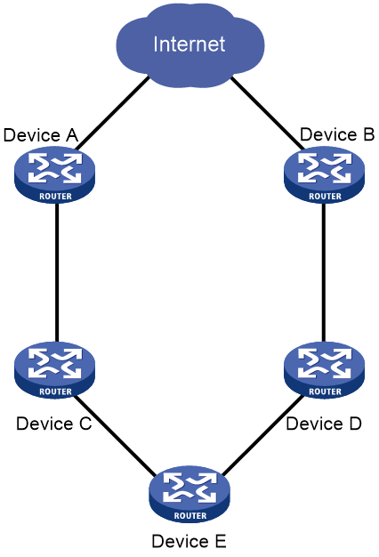
To enable prioritized advertisement of default-route withdrawal messages:
|
Step |
Command |
Remarks |
|
1. Enter system view. |
system-view |
N/A |
|
2. Enter BGP instance view. |
bgp as-number [ instance instance-name ] |
N/A |
|
3. Enable prioritized advertisement of default-route withdrawal messages. |
default-route update-first |
By default, BGP does not send withdrawal messages of the default route prior to other routes. |
Limiting routes received from a peer or peer group
This feature can prevent attacks that send a large number of BGP routes to the router.
If the number of routes received from a peer or peer group exceeds the upper limit, the router takes one of the following actions based on your configuration:
· Tears down the BGP session to the peer or peer group and does not attempt to re-establish the session.
· Continues to receive routes from the peer or peer group and generates a log message.
· Retains the session to the peer or peer group, but it discards excess routes and generates a log message.
· Tears down the BGP session to the peer or peer group and, after a specific period of time, re-establishes a BGP session to the peer or peer group.
You can specify a percentage threshold for the router to generate a log message. When the ratio of the number of received routes to the maximum number reaches the percentage value, the router generates a log message.
To limit routes that a router can receive from a peer or peer group (IPv4 unicast/multicast address family):
|
Step |
Command |
Remarks |
|
1. Enter system view. |
system-view |
N/A |
|
2. Enter BGP IPv4 unicast address family view, BGP-VPN IPv4 unicast address family view, or BGP IPv4 multicast address family view. |
· Enter BGP IPv4 unicast address family view: a. bgp as-number [ instance instance-name ] b. address-family ipv4 [ unicast ] · Enter BGP-VPN IPv4 unicast address family view: a. bgp as-number [ instance instance-name ] b. ip vpn-instance vpn-instance-name c. address-family ipv4 [ unicast ] · Enter BGP IPv4 multicast address family view: a. bgp as-number [ instance instance-name ] b. address-family ipv4 multicast |
N/A |
|
3. Specify the maximum number of routes that a router can receive from a peer or peer group. |
peer { group-name | ipv4-address [ mask-length ] } route-limit prefix-number [ { alert-only | discard | reconnect reconnect-time } | percentage-value ] * |
By default, the number of routes that a router can receive from a peer or peer group is not limited. |
To limit routes that a router can receive from a peer or peer group (IPv6 unicast/multicast address family):
|
Step |
Command |
Remarks |
|
1. Enter system view. |
system-view |
N/A |
|
2. Enter BGP IPv6 unicast address family view, BGP-VPN IPv6 unicast address family view, or BGP IPv6 multicast address family view. |
· Enter BGP IPv6 unicast address family view: a. bgp as-number [ instance instance-name ] b. address-family ipv6 [ unicast ] · Enter BGP-VPN IPv6 unicast address family view: a. bgp as-number [ instance instance-name ] b. ip vpn-instance vpn-instance-name c. address-family ipv6 [ unicast ] · Enter BGP IPv6 multicast address family view: a. bgp as-number [ instance instance-name ] b. address-family ipv6 multicast |
N/A |
|
3. Specify the maximum number of routes that a router can receive from a peer or peer group. |
peer { group-name | ipv6-address [ prefix-length ] } route-limit prefix-number [ { alert-only | discard | reconnect reconnect-time } | percentage-value ] * |
By default, the number of routes that a router can receive from a peer or peer group is not limited. |
Configuring BGP route filtering policies
Configuration prerequisites
Before you configure BGP routing filtering policies, configure the following filters used for route filtering as needed:
· ACL (see ACL and QoS Configuration Guide).
· Prefix list (see "Configuring routing policies").
· Routing policy (see "Configuring routing policies").
· AS path list (see "Configuring routing policies").
Configuring BGP route distribution filtering policies
To configure BGP route distribution filtering policies, use the following methods:
· Use an ACL or prefix list to filter routing information advertised to all peers.
· Use a routing policy, ACL, AS path list, or prefix list to filter routing information advertised to a peer or peer group.
If you configure multiple filtering policies, apply them in the following sequence:
1. filter-policy export
2. peer filter-policy export
3. peer as-path-acl export
4. peer prefix-list export
5. peer route-policy export
Only routes passing all the configured policies can be advertised.
To configure BGP route distribution filtering policies (IPv4 unicast/multicast address family):
|
Step |
Command |
Remarks |
|
1. Enter system view. |
system-view |
N/A |
|
2. Enter BGP IPv4 unicast address family view, BGP-VPN IPv4 unicast address family view, or BGP IPv4 multicast address family view. |
· Enter BGP IPv4 unicast address family view: a. bgp as-number [ instance instance-name ] b. address-family ipv4 [ unicast ] · Enter BGP-VPN IPv4 unicast address family view: a. bgp as-number [ instance instance-name ] b. ip vpn-instance vpn-instance-name c. address-family ipv4 [ unicast ] · Enter BGP IPv4 multicast address family view: a. bgp as-number [ instance instance-name ] b. address-family ipv4 multicast |
N/A |
|
3. Configure BGP route distribution filtering policies. |
· Reference an ACL or IP prefix list to filter advertised
BGP routes: · Reference a routing policy to filter BGP
routes advertised to a peer or peer group: · Reference an ACL to filter BGP routes
advertised to a peer or peer group: · Reference an AS path list to filter BGP
routes advertised to a peer or peer group: · Reference an IPv4 prefix list to filter BGP
routes advertised to a peer or peer group: |
Use at least one method. By default, no BGP distribution filtering policy is configured. |
To configure BGP route distribution filtering policies (IPv6 unicast/multicast address family):
|
Step |
Command |
Remarks |
|
1. Enter system view. |
system-view |
N/A |
|
2. Enter BGP IPv6 unicast address family view, BGP-VPN IPv6 unicast address family view, or BGP IPv6 multicast address family view. |
· Enter BGP IPv6 unicast address family view: a. bgp as-number [ instance instance-name ] b. address-family ipv6 [ unicast ] · Enter BGP-VPN IPv6 unicast address family view: a. bgp as-number [ instance instance-name ] b. ip vpn-instance vpn-instance-name c. address-family ipv6 [ unicast ] · Enter BGP IPv6 multicast address family view: a. bgp as-number [ instance instance-name ] b. address-family ipv6 multicast |
N/A |
|
3. Configure BGP route distribution filtering policies. |
· Reference an ACL or IPv6 prefix list to filter
advertised BGP routes: · Reference a routing policy to filter BGP
routes advertised to a peer or peer group: · Reference an ACL to filter BGP routes
advertised to a peer or peer group: · Reference an AS path list to filter BGP
routes advertised to a peer or peer group: · Reference an IPv6 prefix list to filter BGP
routes advertised to a peer or peer group |
Use at least one method. By default, no BGP distribution filtering policy is configured. |
Configuring BGP route reception filtering policies
You can use the following methods to configure BGP route reception filtering policies:
· Use an ACL or prefix list to filter routing information received from all peers.
· Use a routing policy, ACL, AS path list, or prefix list to filter routing information received from a peer or peer group.
If you configure multiple filtering policies, apply them in the following sequence:
1. filter-policy import
2. peer filter-policy import
3. peer as-path-acl import
4. peer prefix-list import
5. peer route-policy import
Only routes passing all the configured policies can be received.
To configure BGP route reception filtering policies (IPv4 unicast/multicast address family):
|
Step |
Command |
Remarks |
|
1. Enter system view. |
system-view |
N/A |
|
2. Enter BGP IPv4 unicast address family view, BGP-VPN IPv4 unicast address family view, or BGP IPv4 multicast address family view. |
· Enter BGP IPv4 unicast address family view: a. bgp as-number [ instance instance-name ] b. address-family ipv4 [ unicast ] · Enter BGP-VPN IPv4 unicast address family view: a. bgp as-number [ instance instance-name ] b. ip vpn-instance vpn-instance-name c. address-family ipv4 [ unicast ] · Enter BGP IPv4 multicast address family view: a. bgp as-number [ instance instance-name ] b. address-family ipv4 multicast |
N/A |
|
3. Configure BGP route reception filtering policies. |
· Reference an ACL or IP prefix list to filter BGP
routes received from all peers: · Reference a routing policy to filter BGP
routes received from a peer or peer group: · Reference an ACL to filter BGP routes received
from a peer or peer group: · Reference an AS path list to filter BGP
routes received from a peer or peer group: · Reference an IPv4 prefix list to filter BGP
routes received from a peer or peer group: |
Use at least one method. By default, no route reception filtering is configured. |
To configure BGP route reception filtering policies (IPv6 unicast/multicast address family):
|
Step |
Command |
Remarks |
|
1. Enter system view. |
system-view |
N/A |
|
2. Enter BGP IPv6 unicast address family view, BGP-VPN IPv6 unicast address family view, or BGP IPv6 multicast address family view. |
· Enter BGP IPv6 unicast address family view: a. bgp as-number [ instance instance-name ] b. address-family ipv6 [ unicast ] · Enter BGP-VPN IPv6 unicast address family view: a. bgp as-number [ instance instance-name ] b. ip vpn-instance vpn-instance-name c. address-family ipv6 [ unicast ] · Enter BGP IPv6 multicast address family view: a. bgp as-number [ instance instance-name ] b. address-family ipv6 multicast |
N/A |
|
3. Configure BGP route reception filtering policies. |
· Reference ACL or IPv6 prefix list to filter BGP
routes received from all peers: · Reference a routing policy to filter BGP
routes received from a peer or peer group: · Reference an ACL to filter BGP routes received
from a peer or peer group: · Reference an AS path list to filter BGP routes
received from a peer or peer group: · Reference an IPv6 prefix list to filter BGP
routes received from a peer or peer group: |
Use at least one method. By default, no route reception filtering is configured. |
Setting the BGP route sending rate
If a device sends many new routes within a short time period, it might be unable to add the routes to the FIB before the peer device adds them. This might result in traffic forwarding failure. To avoid this problem, you can perform this task to set an appropriate route sending rate for the device.
For a device with high performance, you can set a high BGP route sending rate as needed. For a device without high performance, set a relatively low BGP route sending rate as a best practice.
This task applies only to IPv4 unicast routes and IPv6 unicast routes.
To set the BGP route sending rate:
|
Step |
Command |
Remarks |
|
1. Enter system view. |
system-view |
N/A |
|
2. Enter BGP instance view. |
bgp as-number [ instance instance-name ] |
N/A |
|
3. Set the BGP route sending rate. |
route-rate-limit rate |
By default, the BGP route sending rate is not set. |
Configuring BGP route update delay
Perform this task to configure BGP to delay sending route updates on reboot to reduce traffic loss. With this feature enabled, BGP redistributes all routes from other neighbors on reboot, selects the optimal route, and then advertises it.
To configure BGP route update delay:
|
Step |
Command |
Remarks |
|
1. Enter system view. |
system-view |
N/A |
|
2. Enter BGP instance view. |
bgp as-number [ instance instance-name ] |
N/A |
|
3. Configure BGP to delay sending route updates on reboot. |
bgp update-delay on-startup seconds |
By default, BGP immediately sends route updates on reboot. |
|
4. (Optional.) Configure BGP to immediately send route updates for routes that match a prefix list. |
bgp update-delay on-startup prefix-list ipv4-prefix-list-name |
By default, no prefix list is specified to filter routes. Use this command when the updates for the specified routes must be sent immediately. This command is available only to IPv4 prefix lists. |
Configuring a startup policy for BGP route updates
About startup policy for BGP route updates
Perform this task to configure BGP to send route updates with the specified attributes within the specified period after reboot.
As shown in Figure 11, if Router B restarts and sends route updates before route convergence completes, traffic sent from Router A through Router B might be lost. This feature enables Router B to send route updates with the specified attribute values within the specified period after reboot, so that Router A can forward traffic through Router C.
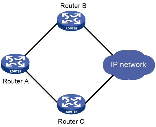
Procedure
To configure a startup policy for BGP route updates:
|
Step |
Command |
Remarks |
|
1. Enter system view. |
system-view |
N/A |
|
2. Enter BGP instance view. |
bgp as-number [ instance instance-name ] |
N/A |
|
3. Specify the period after reboot within which the startup policy is effective. |
bgp apply-policy on-startup duration seconds |
By default, the startup policy does not take effect. |
|
4. Specify a MED attribute value in the startup policy. |
bgp policy on-startup med med-value |
By default, the MED attribute value in the startup policy is 4294967295. |
Configuring BGP route dampening
Route dampening enables BGP to not select unstable routes as optimal routes. This feature applies to EBGP routes but not to IBGP routes.
If an EBGP peer goes down after you configure this feature, routes coming from the peer are dampened but not deleted.
To configure BGP route dampening (IPv4 unicast/multicast address family):
|
Step |
Command |
Remarks |
|
1. Enter system view. |
system-view |
N/A |
|
2. Enter BGP IPv4 unicast address family view, BGP-VPN IPv4 unicast address family view, or BGP IPv4 multicast address family view. |
· Enter BGP IPv4 unicast address family view: a. bgp as-number [ instance instance-name ] b. address-family ipv4 [ unicast ] · Enter BGP-VPN IPv4 unicast address family view: a. bgp as-number [ instance instance-name ] b. ip vpn-instance vpn-instance-name c. address-family ipv4 [ unicast ] · Enter BGP IPv4 multicast address family view: a. bgp as-number [ instance instance-name ] b. address-family ipv4 multicast |
N/A |
|
3. Configure BGP route dampening. |
dampening [ half-life-reachable half-life-unreachable reuse suppress ceiling | route-policy route-policy-name ] * |
By default, BGP route dampening is not configured. |
To configure BGP route dampening (IPv6 unicast/multicast address family):
|
Step |
Command |
Remarks |
|
1. Enter system view. |
system-view |
N/A |
|
2. Enter BGP IPv6 unicast address family view, BGP-VPN IPv6 unicast address family view, or BGP IPv6 multicast address family view. |
· Enter BGP IPv6 unicast address family view: a. bgp as-number [ instance instance-name ] b. address-family ipv6 [ unicast ] · Enter BGP-VPN IPv6 unicast address family view: a. bgp as-number [ instance instance-name ] b. ip vpn-instance vpn-instance-name c. address-family ipv6 [ unicast ] · Enter BGP IPv6 multicast address family view: a. bgp as-number [ instance instance-name ] b. address-family ipv6 multicast |
N/A |
|
3. Configure IPv6 BGP route dampening. |
dampening [ half-life-reachable half-life-unreachable reuse suppress ceiling | route-policy route-policy-name ] * |
By default, IPv6 BGP route dampening is not configured. |
Controlling BGP path selection
By configuring BGP path attributes, you can control BGP path selection.
Setting a preferred value for routes received
Perform this task to set a preferred value for specific routes to control BGP path selection.
Among multiple routes that have the same destination/mask and are learned from different peers, the one with the greatest preferred value is selected as the optimal route.
To set a preferred value for routes from a peer or peer group (IPv4 unicast/multicast address family):
|
Step |
Command |
Remarks |
|
1. Enter system view. |
system-view |
N/A |
|
2. Enter BGP IPv4 unicast address family view, BGP-VPN IPv4 unicast address family view, or BGP IPv4 multicast address family view. |
· Enter BGP IPv4 unicast address family view: a. bgp as-number [ instance instance-name ] b. address-family ipv4 [ unicast ] · Enter BGP-VPN IPv4 unicast address family view: a. bgp as-number [ instance instance-name ] b. ip vpn-instance vpn-instance-name c. address-family ipv4 [ unicast ] · Enter BGP IPv4 multicast address family view: a. bgp as-number [ instance instance-name ] b. address-family ipv4 multicast |
N/A |
|
3. Set a preferred value for routes received from a peer or peer group. |
peer { group-name | ipv4-address [ mask-length ] } preferred-value value |
The default preferred value is 0. |
To set a preferred value for routes from a peer or peer group (IPv6 unicast/multicast address family):
|
Step |
Command |
Remarks |
|
1. Enter system view. |
system-view |
N/A |
|
2. Enter BGP IPv6 unicast address family view, BGP-VPN IPv6 unicast address family view, or BGP IPv6 multicast address family view. |
· Enter BGP IPv6 unicast address family view: a. bgp as-number [ instance instance-name ] b. address-family ipv6 [ unicast ] · Enter BGP-VPN IPv6 unicast address family view: a. bgp as-number [ instance instance-name ] b. ip vpn-instance vpn-instance-name c. address-family ipv6 [ unicast ] · Enter BGP IPv6 multicast address family view: a. bgp as-number [ instance instance-name ] b. address-family ipv6 multicast |
N/A |
|
3. Set a preferred value for routes received from a peer or peer group. |
peer { group-name | ipv6-address [ prefix-length ] } preferred-value value |
The default preferred value is 0. |
Configuring preferences for BGP routes
Routing protocols each have a default preference. If they find multiple routes destined for the same network, the route found by the routing protocol with the highest preference is selected as the optimal route.
You can use the preference command to modify preferences for EBGP, IBGP, and local BGP routes, or use a routing policy to set a preference for matching routes. For routes not matching the routing policy, the default preference applies.
If a device has an EBGP route and a local BGP route to reach the same destination, it does not select the EBGP route because the EBGP route has a lower preference than the local BGP route by default. You can use the network short-cut command to configure the EBGP route as a shortcut route that has the same preference as the local BGP route. The EBGP route will more likely become the optimal route.
To configure preferences for BGP routes (IPv4 unicast/multicast address family):
|
Step |
Command |
Remarks |
|
1. Enter system view. |
system-view |
N/A |
|
2. Enter BGP IPv4 unicast address family view, BGP-VPN IPv4 unicast address family view, or BGP IPv4 multicast address family view. |
· Enter BGP IPv4 unicast address family view: a. bgp as-number [ instance instance-name ] b. address-family ipv4 [ unicast ] · Enter BGP-VPN IPv4 unicast address family view: a. bgp as-number [ instance instance-name ] b. ip vpn-instance vpn-instance-name c. address-family ipv4 [ unicast ] · Enter BGP IPv4 multicast address family view: a. bgp as-number [ instance instance-name ] b. address-family ipv4 multicast |
N/A |
|
3. Configure preferences for EBGP, IBGP, and local BGP routes. |
preference { external-preference internal-preference local-preference | route-policy route-policy-name } |
The default preferences for EBGP, IBGP, and local BGP routes are 255, 255, and 130. |
|
4. Configure an EBGP route as a shortcut route. |
network ipv4-address [ mask-length | mask ] short-cut |
By default, an EBGP route has a preference of 255. |
To configure preferences for BGP routes (IPv6 unicast/multicast address family):
|
Step |
Command |
Remarks |
|
1. Enter system view. |
system-view |
N/A |
|
2. Enter BGP IPv6 unicast address family view, BGP-VPN IPv6 unicast address family view, or BGP IPv6 multicast address family view. |
· Enter BGP IPv6 unicast address family view: a. bgp as-number [ instance instance-name ] b. address-family ipv6 [ unicast ] · Enter BGP-VPN IPv6 unicast address family view: a. bgp as-number [ instance instance-name ] b. ip vpn-instance vpn-instance-name c. address-family ipv6 [ unicast ] · Enter BGP IPv6 multicast address family view: a. bgp as-number [ instance instance-name ] b. address-family ipv6 multicast |
N/A |
|
3. Configure preferences for EBGP, IBGP, and local BGP routes. |
preference { external-preference internal-preference local-preference | route-policy route-policy-name } |
The default preferences for EBGP, IBGP, and local BGP routes are 255, 255, and 130. |
|
4. Configure an EBGP route as a shortcut route. |
network ipv6-address prefix-length short-cut |
By default, an EBGP route has a preference of 255. |
Configuring the default local preference
The local preference is used to determine the optimal route for traffic leaving the local AS. When a BGP router obtains from several IBGP peers multiple routes to the same destination, but with different next hops, it considers the route with the highest local preference as the optimal route.
This task allows you to specify the default local preference for routes sent to IBGP peers.
To specify the default local preference (IPv4 unicast/multicast address family):
|
Step |
Command |
Remarks |
|
1. Enter system view. |
system-view |
N/A |
|
2. Enter BGP IPv4 unicast address family view, BGP-VPN IPv4 unicast address family view, or BGP IPv4 multicast address family view. |
· Enter BGP IPv4 unicast address family view: a. bgp as-number [ instance instance-name ] b. address-family ipv4 [ unicast ] · Enter BGP-VPN IPv4 unicast address family view: a. bgp as-number [ instance instance-name ] b. ip vpn-instance vpn-instance-name c. address-family ipv4 [ unicast ] · Enter BGP IPv4 multicast address family view: a. bgp as-number [ instance instance-name ] b. address-family ipv4 multicast |
N/A |
|
3. Configure the default local preference. |
default local-preference value |
The default local preference is 100. |
To specify the default local preference (IPv6 unicast/multicast address family):
|
Step |
Command |
Remarks |
|
1. Enter system view. |
system-view |
N/A |
|
2. Enter BGP IPv6 unicast address family view, BGP-VPN IPv6 unicast address family view, or BGP IPv6 multicast address family view. |
· Enter BGP IPv6 unicast address family view: a. bgp as-number [ instance instance-name ] b. address-family ipv6 [ unicast ] · Enter BGP-VPN IPv6 unicast address family view: a. bgp as-number [ instance instance-name ] b. ip vpn-instance vpn-instance-name c. address-family ipv6 [ unicast ] · Enter BGP IPv6 multicast address family view: a. bgp as-number [ instance instance-name ] b. address-family ipv6 multicast |
N/A |
|
3. Configure the default local preference. |
default local-preference value |
The default local preference is 100. |
Configuring the MED attribute
BGP uses MED to determine the optimal route for traffic going into an AS. When a BGP router obtains multiple routes with the same destination but with different next hops, it considers the route with the smallest MED value as the optimal route if other conditions are the same.
Configuring the default MED value
To configure the default MED value (IPv4 unicast/multicast address family):
|
Step |
Command |
Remarks |
|
1. Enter system view. |
system-view |
N/A |
|
2. Enter BGP IPv4 unicast address family view, BGP-VPN IPv4 unicast address family view, or BGP IPv4 multicast address family view. |
· Enter BGP IPv4 unicast address family view: a. bgp as-number [ instance instance-name ] b. address-family ipv4 [ unicast ] · Enter BGP-VPN IPv4 unicast address family view: a. bgp as-number [ instance instance-name ] b. ip vpn-instance vpn-instance-name c. address-family ipv4 [ unicast ] · Enter BGP IPv4 multicast address family view: a. bgp as-number [ instance instance-name ] b. address-family ipv4 multicast |
N/A |
|
3. Configure the default MED value. |
default med med-value |
The default MED value is 0. |
To configure the default MED value (IPv6 unicast/multicast address family):
|
Step |
Command |
Remarks |
|
1. Enter system view. |
system-view |
N/A |
|
2. Enter BGP IPv6 unicast address family view, BGP-VPN IPv6 unicast address family view, or BGP IPv6 multicast address family view. |
· Enter BGP IPv6 unicast address family view: a. bgp as-number [ instance instance-name ] b. address-family ipv6 [ unicast ] · Enter BGP-VPN IPv6 unicast address family view: a. bgp as-number [ instance instance-name ] b. ip vpn-instance vpn-instance-name c. address-family ipv6 [ unicast ] · Enter BGP IPv6 multicast address family view: a. bgp as-number [ instance instance-name ] b. address-family ipv6 multicast |
N/A |
|
3. Configure the default MED value. |
default med med-value |
The default MED value is 0. |
Enabling MED comparison for routes from different ASs
This task enables BGP to compare the MEDs of routes from different ASs.
To enable MED comparison for routes from different ASs:
|
Step |
Command |
Remarks |
|
1. Enter system view. |
system-view |
N/A |
|
2. Enter BGP instance view or BGP-VPN instance view. |
· Enter BGP instance view: · Enter BGP-VPN instance view: a. bgp as-number [ instance instance-name ] b. ip vpn-instance vpn-instance-name |
N/A |
|
3. Enable MED comparison for routes from different ASs. |
compare-different-as-med |
By default, MED comparison for routes from different ASs is disabled. |
Enabling MED comparison for routes on a per-AS basis
This task enables BGP to compare the MEDs of routes from an AS.
Figure 12 Route selection based on MED (in an IPv4 network)
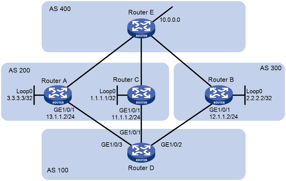
As shown in Figure 12, Router D establishes indirect EBGP peer relationships with Router A, Router B, and Router C, and learns addresses 1.1.1.1/32, 2.2.2.2/32, and 3.3.3.3/32 through OSPF. The following output shows the routing information on Router D.
Destination/Mask Proto Pre Cost NextHop Interface
1.1.1.1/32 O_INTRA 10 10 11.1.1.2 XGE1/0/1
2.2.2.2/32 O_INTRA 10 20 12.1.1.2 XGE1/0/2
3.3.3.3/32 O_INTRA 10 30 13.1.1.2 XGE1/0/3
Router D learns network 10.0.0.0 from both Router A and Router B. Because the route learned from Router B has a smaller IGP metric, the route is optimal. The following output shows the BGP routing table on Router D.
Network NextHop MED LocPrf PrefVal Path/Ogn
*>e 10.0.0.0 2.2.2.2 50 0 300 400e
* e 3.3.3.3 50 0 200 400e
When Router D learns network 10.0.0.0 from Router C, it compares the route with the optimal route in its routing table. Because Router C and Router B reside in different ASs, BGP does not compare the MEDs of the two routes. The route from Router C has a smaller IGP metric than the route from Router B, so the route from Router C becomes optimal. The following output shows the BGP routing table on Router D.
Network NextHop MED LocPrf PrefVal Path/Ogn
*>e 10.0.0.0 1.1.1.1 60 0 200 400e
* e 10.0.0.0 2.2.2.2 50 0 300 400e
* e 3.3.3.3 50 0 200 400e
However, Router C and Router A reside in the same AS, and Router C has a greater MED, so network 10.0.0.0 learned from Router C should not be optimal.
To avoid this problem, you can configure the bestroute compare-med command to enable MED comparison for routes from the same AS on Router D. After that, Router D puts the routes received from each AS into a group, selects the route with the lowest MED from each group, and compares routes from different groups. Network 10.0.0.0 learned from Router B is the optimal route. The following output shows the BGP routing table on Router D.
Network NextHop MED LocPrf PrefVal Path/Ogn
*>e 10.0.0.0 2.2.2.2 50 0 300 400e
* e 3.3.3.3 50 0 200 400e
* e 1.1.1.1 60 0 200 400e
To enable MED comparison for routes on a per-AS basis:
|
Step |
Command |
Remarks |
|
1. Enter system view. |
system-view |
N/A |
|
2. Enter BGP instance view or BGP-VPN instance view. |
· Enter BGP instance view: · Enter BGP-VPN instance view: a. bgp as-number [ instance instance-name ] b. ip vpn-instance vpn-instance-name |
N/A |
|
3. Enable MED comparison for routes on a per-AS basis. |
bestroute compare-med |
By default, MED comparison for routes on a per-AS basis is disabled. |
Enabling MED comparison for routes from confederation peers
This task enables BGP to compare the MEDs of routes received from confederation peers. However, if a route received from a confederation peer has an AS number that does not belong to the confederation, BGP does not compare the route with other routes. For example, a confederation has three AS numbers 65006, 65007, and 65009. BGP receives three routes from different confederation peers. The AS_PATH attributes of these routes are 65006 65009, 65007 65009, and 65008 65009, and the MED values of them are 2, 3, and 1. Because the third route's AS_PATH attribute contains AS number 65008 that does not belong to the confederation, BGP does not compare it with other routes. As a result, the first route becomes the optimal route.
To enable MED comparison for routes from confederation peers:
|
Step |
Command |
Remarks |
|
1. Enter system view. |
system-view |
N/A |
|
2. Enter BGP instance view or BGP-VPN instance view. |
· Enter BGP instance view: · Enter BGP-VPN instance view: a. bgp as-number [ instance instance-name ] b. ip vpn-instance vpn-instance-name |
N/A |
|
3. Enable MED comparison for routes from confederation peers. |
bestroute med-confederation |
By default, MED comparison for routes from confederation peers is disabled. |
Configuring the NEXT_HOP attribute
By default, a BGP router does not set itself as the next hop for routes advertised to an IBGP peer or peer group. In some cases, however, you must configure the advertising router as the next hop to ensure that the BGP peer can find the correct next hop.
For example, as shown in Figure 13, Router A and Router B establish an EBGP neighbor relationship, and Router B and Router C establish an IBGP neighbor relationship. If Router C has no route destined for IP address 1.1.1.1/24, you must configure Router B to set itself 3.1.1.1/24 as the next hop for the network 2.1.1.1/24 advertised to Router C.
Figure 13 NEXT_HOP attribute configuration
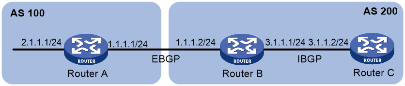
If a BGP router has two peers on a broadcast network, it does not set itself as the next hop for routes sent to an EBGP peer by default. As shown in Figure 14, Router A and Router B establish an EBGP neighbor relationship, and Router B and Router C establish an IBGP neighbor relationship. They are on the same broadcast network 1.1.1.0/24. When Router B sends EBGP routes to Router A, it does not set itself as the next hop by default. However, you can configure Router B to set it (1.1.1.2/24) as the next hop for routes sent to Router A by using the peer next-hop-local command as needed.
Figure 14 NEXT_HOP attribute configuration
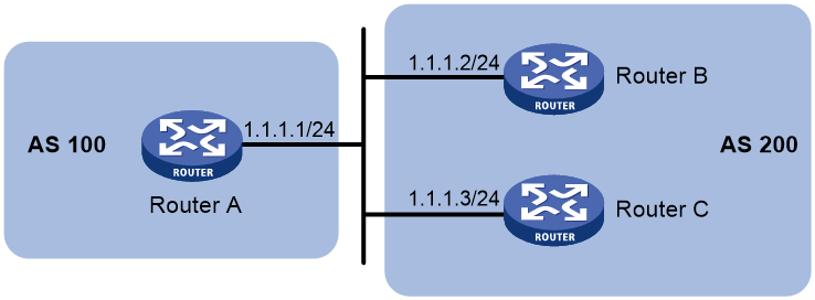
|
|
IMPORTANT: If you have configured BGP load balancing, the router sets itself as the next hop for routes sent to an IBGP peer or peer group regardless of whether the peer next-hop-local command is configured. |
To configure the NEXT_HOP attribute (IPv4 unicast/multicast address family):
|
Step |
Command |
Remarks |
|
1. Enter system view. |
system-view |
N/A |
|
2. Enter BGP IPv4 unicast address family view, BGP-VPN IPv4 unicast address family view, or BGP IPv4 multicast address family view. |
· Enter BGP IPv4 unicast address family view: a. bgp as-number [ instance instance-name ] b. address-family ipv4 [ unicast ] · Enter BGP-VPN IPv4 unicast address family view: a. bgp as-number [ instance instance-name ] b. ip vpn-instance vpn-instance-name c. address-family ipv4 [ unicast ] · Enter BGP IPv4 multicast address family view: a. bgp as-number [ instance instance-name ] b. address-family ipv4 multicast |
N/A |
|
3. Specify the router as the next hop for routes sent to a peer or peer group. |
peer { group-name | ipv4-address [ mask-length ] } next-hop-local |
By default, the router sets itself as the next hop for routes sent to an EBGP peer or peer group. However, it does not set itself as the next hop for routes sent to an IBGP peer or peer group. |
To configure the NEXT_HOP attribute (IPv6 unicast/multicast address family):
|
Step |
Command |
Remarks |
|
1. Enter system view. |
system-view |
N/A |
|
2. Enter BGP IPv6 unicast address family view, BGP-VPN IPv6 unicast address family view, or BGP IPv6 multicast address family view. |
· Enter BGP IPv6 unicast address family view: a. bgp as-number [ instance instance-name ] b. address-family ipv6 [ unicast ] · Enter BGP-VPN IPv6 unicast address family view: a. bgp as-number [ instance instance-name ] b. ip vpn-instance vpn-instance-name c. address-family ipv6 [ unicast ] · Enter BGP IPv6 multicast address family view: a. bgp as-number [ instance instance-name ] b. address-family ipv6 multicast |
N/A |
|
3. Specify the router as the next hop for routes sent to a peer or peer group. |
peer { group-name | ipv6-address [ prefix-length ] } next-hop-local |
By default, the router sets itself as the next hop for routes sent to an EBGP peer or peer group. However, it does not set itself as the next hop for routes sent to an IBGP peer or peer group. |
Configuring the AS_PATH attribute
Permitting local AS number to appear in routes from a peer or peer group
In general, BGP checks whether the AS_PATH attribute of a route from a peer contains the local AS number. If yes, it discards the route to avoid routing loops.
In certain network environments, however, the AS_PATH attribute of a route from a peer must be allowed to contain the local AS number. Otherwise, the route cannot be advertised correctly.
To permit the local AS number to appear in routes from a peer or peer group and specify the appearance times (IPv4 unicast/multicast address family):
|
Step |
Command |
Remarks |
|
1. Enter system view. |
system-view |
N/A |
|
2. Enter BGP IPv4 unicast address family view, BGP-VPN IPv4 unicast address family view, or BGP IPv4 multicast address family view. |
· Enter BGP IPv4 unicast address family view: a. bgp as-number [ instance instance-name ] b. address-family ipv4 [ unicast ] · Enter BGP-VPN IPv4 unicast address family view: a. bgp as-number [ instance instance-name ] b. ip vpn-instance vpn-instance-name c. address-family ipv4 [ unicast ] · Enter BGP IPv4 multicast address family view: a. bgp as-number [ instance instance-name ] b. address-family ipv4 multicast |
N/A |
|
3. Permit the local AS number to appear in routes from a peer or peer group and set the appearance times. |
peer { group-name | ipv4-address [ mask-length ] } allow-as-loop [ number ] |
By default, the local AS number is not allowed in routes from a peer or peer group. |
To permit the local AS number to appear in routes from a peer or peer group and specify the appearance times (IPv6 unicast/multicast address family):
|
Step |
Command |
Remarks |
|
1. Enter system view. |
system-view |
N/A |
|
2. Enter BGP IPv6 unicast address family view, BGP-VPN IPv6 unicast address family view, or BGP IPv6 multicast address family view. |
· Enter BGP IPv6 unicast address family view: a. bgp as-number [ instance instance-name ] b. address-family ipv6 [ unicast ] · Enter BGP-VPN IPv6 unicast address family view: a. bgp as-number [ instance instance-name ] b. ip vpn-instance vpn-instance-name c. address-family ipv6 [ unicast ] · Enter BGP IPv6 multicast address family view: a. bgp as-number [ instance instance-name ] b. address-family ipv6 multicast |
N/A |
|
3. Permit the local AS number to appear in routes from a peer or peer group and set the appearance times. |
peer { group-name | ipv6-address [ prefix-length ] } allow-as-loop [ number ] |
By default, the local AS number is not allowed in routes from a peer or peer group. |
Ignoring the AS_PATH attribute during optimal route selection
|
Step |
Command |
Remarks |
|
1. Enter system view. |
system-view |
N/A |
|
2. Enter BGP instance view or BGP-VPN instance view. |
· Enter BGP instance view: · Enter BGP-VPN instance view: a. bgp as-number [ instance instance-name ] b. ip vpn-instance vpn-instance-name |
N/A |
|
3. Configure BGP to ignore the AS_PATH attribute during optimal route selection |
bestroute as-path-neglect |
By default, BGP considers AS_PATH during optimal route selection. |
Advertising a fake AS number to a peer or peer group
After you move a BGP router from an AS to another AS (from AS 2 to AS 3 for example), you have to modify the AS number of the router on all its EBGP peers. To avoid such modifications, you can configure the router to advertise a fake AS number 2 to its EBGP peers so that the EBGP peers still think that Router A is in AS 2.
To advertise a fake AS number to a peer or peer group (IPv4 unicast/multicast address family):
|
Step |
Command |
Remarks |
|
1. Enter system view. |
system-view |
N/A |
|
2. Enter BGP instance view or BGP-VPN instance view. |
· Enter BGP instance view: · Enter BGP-VPN instance view: a. bgp as-number [ instance instance-name ] b. ip vpn-instance vpn-instance-name |
N/A |
|
3. Advertise a fake AS number to a peer or peer group. |
peer { group-name | ipv4-address [ mask-length ] } fake-as as-number |
By default, no fake AS number is advertised to a peer or peer group. This command applies only to EBGP peers or EBGP peer groups. |
To advertise a fake AS number to a peer or peer group (IPv6 unicast/multicast address family):
|
Step |
Command |
Remarks |
|
1. Enter system view. |
system-view |
N/A |
|
2. Enter BGP instance view or BGP-VPN instance view. |
· Enter BGP instance view: · Enter BGP-VPN instance view: a. bgp as-number [ instance instance-name ] b. ip vpn-instance vpn-instance-name |
N/A |
|
3. Advertise a fake AS number to a peer or peer group. |
peer { group-name | ipv6-address [ prefix-length ] } fake-as as-number |
By default, no fake AS number is advertised to a peer or peer group. This command applies only to EBGP peers or EBGP peer groups. |
Configuring AS number substitution
|
|
IMPORTANT: Do not configure AS number substitution in normal circumstances. Otherwise, routing loops might occur. |
To use EBGP between PE and CE in MPLS L3VPN, VPN sites in different geographical areas should have different AS numbers. Otherwise, BGP discards route updates containing the local AS number. If two CEs connected to different PEs use the same AS number, you must configure AS number substitution on each PE. This substitution can replace the AS number in route updates originated by the remote CE as its own AS number before advertising them to the connected CE.
Figure 15 AS number substitution configuration (in an IPv4 network)
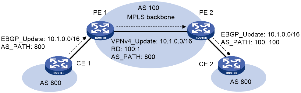
As shown in Figure 15, CE 1 and CE 2 use the same AS number 800. To ensure bidirectional communication between the two sites, configure AS number substitution on PE 2. PE 2 replaces AS 800 with AS 100 for the BGP route update originated from CE 1 before advertising it to CE 2. Perform the same configuration on PE 1.
To configure AS number substitution for a peer or peer group (IPv4 unicast/multicast address family):
|
Step |
Command |
Remarks |
|
1. Enter system view. |
system-view |
N/A |
|
2. Enter BGP instance view or BGP-VPN instance view. |
· Enter BGP instance view: · Enter BGP-VPN instance view: a. bgp as-number [ instance instance-name ] b. ip vpn-instance vpn-instance-name |
N/A |
|
3. Configure AS number substitution for a peer or peer group. |
peer { group-name | ipv4-address [ mask-length ] } substitute-as |
By default, AS number substitution is not configured. |
To configure AS number substitution for a peer or peer group (IPv6 unicast/multicast address family):
|
Step |
Command |
Remarks |
|
1. Enter system view. |
system-view |
N/A |
|
2. Enter BGP instance view or BGP-VPN instance view. |
· Enter BGP instance view: · Enter BGP-VPN instance view: a. bgp as-number [ instance instance-name ] b. ip vpn-instance vpn-instance-name |
N/A |
|
3. Configure AS number substitution for a peer or peer group. |
peer { group-name | ipv6-address [ prefix-length ] } substitute-as |
By default, AS number substitution is not configured. |
Removing private AS numbers from updates sent to an EBGP peer or peer group
Private AS numbers are typically used in test networks, and should not be transmitted in public networks. The range of private AS numbers is from 64512 to 65535.
To remove private AS numbers from updates sent to an EBGP peer or peer group (IPv4 unicast/multicast address family):
|
Step |
Command |
Remarks |
|
1. Enter system view. |
system-view |
N/A |
|
2. Enter BGP IPv4 unicast address family view, BGP-VPN IPv4 unicast address family view, or BGP IPv4 multicast address family view. |
· Enter BGP IPv4 unicast address family view: a. bgp as-number [ instance instance-name ] b. address-family ipv4 [ unicast ] · Enter BGP-VPN IPv4 unicast address family view: a. bgp as-number [ instance instance-name ] b. ip vpn-instance vpn-instance-name c. address-family ipv4 [ unicast ] · Enter BGP IPv4 multicast address family view: a. bgp as-number [ instance instance-name ] b. address-family ipv4 multicast |
N/A |
|
3. Configure BGP to remove private AS numbers from the AS_PATH attribute of updates sent to an EBGP peer or peer group. |
peer { group-name | ipv4-address [ mask-length ] } public-as-only |
By default, BGP updates sent to an EBGP peer or peer group can carry both public and private AS numbers. This command is applicable only to EBGP peers or peer groups. |
To remove private AS numbers from updates sent to an EBGP peer or peer group (IPv6 unicast/multicast address family):
|
Step |
Command |
Remarks |
|
1. Enter system view. |
system-view |
N/A |
|
2. Enter BGP IPv6 unicast address family view, BGP-VPN IPv6 unicast address family view, or BGP IPv6 multicast address family view. |
· Enter BGP IPv6 unicast address family view: a. bgp as-number [ instance instance-name ] b. address-family ipv6 [ unicast ] · Enter BGP-VPN IPv6 unicast address family view: a. bgp as-number [ instance instance-name ] b. ip vpn-instance vpn-instance-name c. address-family ipv6 [ unicast ] · Enter BGP IPv6 multicast address family view: a. bgp as-number [ instance instance-name ] b. address-family ipv6 multicast |
N/A |
|
3. Configure BGP to remove private AS numbers from the AS_PATH attribute of updates sent to an EBGP peer or peer group. |
peer { group-name | ipv6-address [ prefix-length ] } public-as-only |
By default, BGP updates sent to an EBGP peer or peer group can carry both public and private AS numbers. This command is applicable only to EBGP peers or peer groups. |
Ignoring the first AS number of EBGP route updates
By default, BGP checks the first AS number of a received EBGP route update. If the first AS number is neither the AS number of the BGP peer nor a private AS number, the BGP router disconnects the BGP session to the peer.
To ignore the first AS number of EBGP route updates:
|
Step |
Command |
Remarks |
|
1. Enter system view. |
system-view |
N/A |
|
2. Enter BGP instance view. |
bgp as-number [ instance instance-name ] |
N/A |
|
3. Configure BGP to ignore the first AS number of EBGP route updates. |
ignore-first-as |
By default, BGP checks the first AS number of EBGP route updates. |
Ignoring IGP metrics during optimal route selection
|
Step |
Command |
Remarks |
|
1. Enter system view. |
system-view |
N/A |
|
2. Enter BGP instance view or BGP-VPN instance view. |
· Enter BGP instance view: · Enter BGP-VPN instance view: a. bgp as-number [ instance instance-name ] b. ip vpn-instance vpn-instance-name |
N/A |
|
3. Configure BGP to ignore IGP metrics during optimal route selection. |
bestroute igp-metric-ignore |
By default, BGP considers IGP metrics during optimal route selection. If multiple routes to the same destination are available, BGP selects the route with the smallest IGP metric as the optimal route. |
Configuring the SoO attribute
After you configure the SoO attribute for a BGP peer or peer group, BGP adds the SoO attribute into the route updates received from the BGP peer or peer group. In addition, before advertising route updates to the peer or peer group, BGP checks the SoO attribute of the route update against the configured SoO attribute. If they are the same, BGP does not advertise the route updates to the BGP peer or peer group.
To configure the SoO attribute (IPv4 unicast/multicast address family):
|
Step |
Command |
Remarks |
|
1. Enter system view. |
system-view |
N/A |
|
2. Enter BGP IPv4 unicast address family view, BGP-VPN IPv4 unicast address family view, or BGP IPv4 multicast address family view. |
· Enter BGP IPv4 unicast address family view: a. bgp as-number [ instance instance-name ] b. address-family ipv4 [ unicast ] · Enter BGP-VPN IPv4 unicast address family view: a. bgp as-number [ instance instance-name ] b. ip vpn-instance vpn-instance-name c. address-family ipv4 [ unicast ] · Enter BGP IPv4 multicast address family view: a. bgp as-number [ instance instance-name ] b. address-family ipv4 multicast |
N/A |
|
3. Configure the SoO attribute for a peer or peer group. |
peer { group-name | ipv4-address [ mask-length ] } soo site-of-origin |
By default, no SoO attribute is configured for a peer or peer group. |
To configure the SoO attribute (IPv6 unicast/multicast address family):
|
Step |
Command |
Remarks |
|
1. Enter system view. |
system-view |
N/A |
|
2. Enter BGP IPv6 unicast address family view, BGP-VPN IPv6 unicast address family view, or BGP IPv6 multicast address family view. |
· Enter BGP IPv6 unicast address family view: a. bgp as-number [ instance instance-name ] b. address-family ipv6 [ unicast ] · Enter BGP-VPN IPv6 unicast address family view: a. bgp as-number [ instance instance-name ] b. ip vpn-instance vpn-instance-name c. address-family ipv6 [ unicast ] · Enter BGP IPv6 multicast address family view: a. bgp as-number [ instance instance-name ] b. address-family ipv6 multicast |
N/A |
|
3. Configure the SoO attribute for a peer or peer group. |
peer { group-name | ipv6-address [ prefix-length ] } soo site-of-origin |
By default, no SoO attribute is configured for a peer or peer group. |
Tuning and optimizing BGP networks
This section describes how to tune and optimize BGP networks.
Configuring the keepalive interval and hold time
BGP sends keepalive messages regularly to keep the BGP session between two routers.
If a router receives no keepalive or update message from a peer within the hold time, it tears down the session.
You can configure the keepalive interval and hold time globally or for a peer or peer group. The individual settings take precedence over the global settings.
The actual keepalive interval and hold time are determined as follows:
· If the hold time settings on the local and peer routers are different, the smaller setting is used. If the hold time is 0, BGP does not send keepalive messages to its peers and never tears down the session.
· If the keepalive interval is not 0, the actual keepalive interval is the smaller one between 1/3 of the hold time and the keepalive interval.
To configure the keepalive interval and hold time (IPv4 unicast/multicast address family):
|
Step |
Command |
Remarks |
|
1. Enter system view. |
system-view |
N/A |
|
2. Enter BGP instance view or BGP-VPN instance view. |
· Enter BGP instance view: · Enter BGP-VPN instance view: a. bgp as-number [ instance instance-name ] b. ip vpn-instance vpn-instance-name |
N/A |
|
3. Configure the keepalive interval and hold time. |
· Configure the global keepalive interval
and hold time: · Configure the keepalive interval and hold
time for a peer or peer group: |
Use at least one method. By default, the keepalive interval is 60 seconds, and hold time is 180 seconds. The timer command takes effect for new BGP sessions and does not affect existing sessions. The timers configured with the timer and peer timer commands do not take effect until a session is re-established (for example, a session is reset). The hold time must be at least three times the keepalive interval. |
To configure the keepalive interval and hold time (IPv6 unicast/multicast address family):
|
Step |
Command |
Remarks |
|
1. Enter system view. |
system-view |
N/A |
|
2. Enter BGP instance view or BGP-VPN instance view. |
· Enter BGP instance view: · Enter BGP-VPN instance view: a. bgp as-number [ instance instance-name ] b. ip vpn-instance vpn-instance-name |
N/A |
|
3. Configure the keepalive interval and hold time. |
· Configure the global keepalive interval
and hold time: · Configure the keepalive interval and
hold time for a peer or peer group: |
Use at least one method. By default, the keepalive interval is 60 seconds, and hold time is 180 seconds. The timer command takes effect for new BGP sessions and does not affect existing sessions. The timers configured with the timer and peer timer commands do not take effect until a session is re-established (for example, a session is reset). The hold time must be at least three times the keepalive interval. |
Setting the session retry timer
About setting the session retry timer
To speed up session establishment to a peer or peer group and route convergence, set a small session retry timer. If the BGP session flaps, you can set a large session retry timer to reduce the impact.
Restrictions and guidelines
The timer set by the peer timer connect-retry command takes precedence over the timer set by the timer connect-retry command.
Setting the session retry timer (IPv4 unicast/multicast address family)
|
Step |
Command |
Remarks |
|
1. Enter system view. |
system-view |
N/A |
|
2. Enter BGP instance view or BGP-VPN instance view. |
· Enter BGP instance view: · Enter BGP-VPN instance view: a. bgp as-number [ instance instance-name ] b. ip vpn-instance vpn-instance-name |
N/A |
|
3. Set the session retry timer. |
· Set the session retry timer for all
peers or peer groups: · Set the session retry timer for a peer or peer
group: |
Use either method. By default, the session retry timer is 32 seconds for a peer or peer group. |
Setting the session retry timer (IPv6 unicast/multicast address family)
|
Step |
Command |
Remarks |
|
1. Enter system view. |
system-view |
N/A |
|
2. Enter BGP instance view or BGP-VPN instance view. |
· Enter BGP instance view: · Enter BGP-VPN instance view: a. bgp as-number [ instance instance-name ] b. ip vpn-instance vpn-instance-name |
N/A |
|
3. Set the session retry timer. |
· Set the session retry timer for all
peers or peer groups: · Set the session retry timer for a peer or peer
group: |
By default, the session retry timer is 32 seconds for a peer or peer group. |
Configuring the interval for sending updates for the same route
A BGP router sends an update message to its peers when a route is changed. If the route changes frequently, the BGP router keeps sending updates for the same route, resulting route flapping. To prevent this situation, perform this task to configure the interval for sending updates for the same route to a peer or peer group.
This feature does not take effect on withdrawn routes. For withdrawn routes, BGP sends the withdrawal messages immediately.
To configure the interval for sending the same update to a peer or peer group (IPv4 unicast/multicast address family):
|
Step |
Command |
Remarks |
|
1. Enter system view. |
system-view |
N/A |
|
2. Enter BGP instance view or BGP-VPN instance view. |
· Enter BGP instance view: · Enter BGP-VPN instance view: a. bgp as-number [ instance instance-name ] b. ip vpn-instance vpn-instance-name |
N/A |
|
3. Configure the interval for sending updates for the same route to a peer or peer group. |
peer { group-name | ipv4-address [ mask-length ] } route-update-interval interval |
By default, the interval is 15 seconds for an IBGP peer and 30 seconds for an EBGP peer. |
To configure the interval for sending the same update to a peer or peer group (IPv6 unicast/multicast address family):
|
Step |
Command |
Remarks |
|
1. Enter system view. |
system-view |
N/A |
|
2. Enter BGP instance view or BGP-VPN instance view. |
· Enter BGP instance view: · Enter BGP-VPN instance view: a. bgp as-number [ instance instance-name ] b. ip vpn-instance vpn-instance-name |
N/A |
|
3. Configure the interval for sending updates for the same route to a peer or peer group. |
peer { group-name | ipv6-address [ prefix-length ] } route-update-interval interval |
By default, the interval is 15 seconds for an IBGP peer and 30 seconds for an EBGP peer. |
Enabling BGP to establish an EBGP session over multiple hops
To establish an EBGP session, two routers must have a direct physical link and use directly connected interfaces. If no direct link is available, you must use the peer ebgp-max-hop command to enable BGP to establish an EBGP session over multiple hops and specify the maximum hops.
When the BGP GTSM feature is enabled, two peers can establish an EBGP session after passing GTSM check, regardless of whether the maximum number of hops is reached.
To enable BGP to establish an indirect EBGP session (IPv4 unicast/multicast address family):
|
Step |
Command |
Remarks |
|
1. Enter system view. |
system-view |
N/A |
|
2. Enter BGP instance view or BGP-VPN instance view. |
· Enter BGP instance view: · Enter BGP-VPN instance view: a. bgp as-number [ instance instance-name ] b. ip vpn-instance vpn-instance-name |
N/A |
|
3. Enable BGP to establish an EBGP session to an indirectly connected peer or peer group and specify the maximum hop count. |
peer { group-name | ipv4-address [ mask-length ] } ebgp-max-hop [ hop-count ] |
By default, BGP cannot establish an EBGP session to an indirectly connected peer or peer group. |
To enable BGP to establish an indirect EBGP session (IPv6 unicast/multicast address family):
|
Step |
Command |
Remarks |
|
1. Enter system view. |
system-view |
N/A |
|
2. Enter BGP instance view or BGP-VPN instance view. |
· Enter BGP instance view: · Enter BGP-VPN instance view: a. bgp as-number [ instance instance-name ] b. ip vpn-instance vpn-instance-name |
N/A |
|
3. Enable BGP to establish an EBGP session to an indirectly connected peer or peer group and specify the maximum hop count. |
peer { group-name | ipv6-address [ prefix-length ] } ebgp-max-hop [ hop-count ] |
By default, BGP cannot establish an EBGP session to an indirectly connected peer or peer group. |
Enabling immediate re-establishment of direct EBGP connections upon link failure
When the link to a directly connected EBGP peer goes down, the router does not re-establish a session to the peer until the hold time timer expires. This feature enables BGP to immediately recreate the session in that situation. When this feature is disabled, route flapping does not affect EBGP session state.
To enable immediate re-establishment of direct EBGP connections:
|
Step |
Command |
Remarks |
|
1. Enter system view. |
system-view |
N/A |
|
2. Enter BGP instance view. |
bgp as-number [ instance instance-name ] |
N/A |
|
3. Enable immediate re-establishment of direct EBGP connections upon link failure. |
ebgp-interface-sensitive |
By default, immediate re-establishment of direct EBGP connections is enabled. |
Enabling BGP ORF capabilities
About BGP ORF
BGP Outbound Route Filtering (ORF) saves the system resources by reducing the route updates that are sent between BGP peers.
The BGP peers negotiate the ORF capabilities through Open messages. After completing the negotiation process, the BGP peers can exchange ORF information (local route reception filtering policy) through route refresh messages. Then, only routes that pass both the local route distribution filtering policy and the received route reception filtering policy can be advertised.
Restrictions and guidelines
You can enable the ORF information sending, receiving, or both sending and receiving capabilities on a BGP router. For two BGP peers to successfully negotiate the ORF capabilities, make sure one end has the sending capability and the other end has the receiving capability.
Enabling BGP ORF capabilities
To enable BGP ORF capabilities (IPv4 unicast/IPv4 multicast):
|
Step |
Command |
Remarks |
|
1. Enter system view. |
system-view |
N/A |
|
2. Enter BGP IPv4 unicast address family view, BGP-VPN IPv4 unicast address family view, or BGP IPv4 multicast address family view. |
· Enter BGP IPv4 unicast address family view: a. bgp as-number [ instance instance-name ] b. address-family ipv4 [ unicast ] · Enter BGP-VPN IPv4 unicast address family view: a. bgp as-number [ instance instance-name ] b. ip vpn-instance vpn-instance-name c. address-family ipv4 [ unicast ] · Enter BGP IPv4 multicast address family view: a. bgp as-number [ instance instance-name ] b. address-family ipv4 multicast |
N/A |
|
3. Enable BGP ORF capabilities. |
peer { group-name | ipv4-address [ mask-length ] } capability-advertise orf prefix-list { both | receive | send } |
By default, BGP ORF capabilities are disabled. |
To enable BGP ORF capabilities (IPv6 unicast/IPv6 multicast):
|
Step |
Command |
Remarks |
|
1. Enter system view. |
system-view |
N/A |
|
2. Enter BGP IPv6 unicast address family view, BGP-VPN IPv6 unicast address family view, or BGP IPv6 multicast address family view. |
· Enter BGP IPv6 unicast address family view: a. bgp as-number [ instance instance-name ] b. address-family ipv6 [ unicast ] · Enter BGP-VPN IPv6 unicast address family view: a. bgp as-number [ instance instance-name ] b. ip vpn-instance vpn-instance-name c. address-family ipv6 [ unicast ] · Enter BGP IPv6 multicast address family view: a. bgp as-number [ instance instance-name ] b. address-family ipv6 multicast |
N/A |
|
3. Enable BGP ORF capabilities. |
peer { group-name | ipv6-address [ prefix-length ] } capability-advertise orf prefix-list { both | receive | send } |
By default, BGP ORF capabilities are disabled. |
Enabling nonstandard BGP ORF capabilities
|
Step |
Command |
Remarks |
|
1. Enter system view. |
system-view |
N/A |
|
2. Enter BGP instance view or BGP-VPN instance view. |
· Enter BGP instance view: · Enter BGP-VPN instance view: a. bgp as-number [ instance instance-name ] b. ip vpn-instance vpn-instance-name |
N/A |
|
3. Enable nonstandard BGP ORF capabilities. |
peer { group-name | ip-address [ mask-length ] | ipv6-address [ prefix-length ] } capability-advertise orf non-standard |
By default, nonstandard BGP ORF capabilities are disabled. To enable the BGP peers to exchange nonstandard ORF information, you must configure this command together with the peer capability-advertise orf prefix-list command. |
Enabling 4-byte AS number suppression
BGP supports 4-byte AS numbers. The 4-byte AS number occupies four bytes, in the range of 1 to 4294967295. By default, a device sends an Open message to the peer device for session establishment. The Open message indicates that the device supports 4-byte AS numbers. If the peer device supports 2-byte AS numbers instead of 4-byte AS numbers, the session cannot be established. To resolve this issue, enable the 4-byte AS number suppression feature. The device then sends an Open message to inform the peer that it does not support 4-byte AS numbers, so the BGP session can be established.
If the peer device supports 4-byte AS numbers, do not enable the 4-byte AS number suppression feature. Otherwise, the BGP session cannot be established.
To enable 4-byte AS number suppression (IPv4 unicast/multicast address family):
|
Step |
Command |
Remarks |
|
1. Enter system view. |
system-view |
N/A |
|
2. Enter BGP instance view or BGP-VPN instance view. |
· Enter BGP instance view: · Enter BGP-VPN instance view: a. bgp as-number [ instance instance-name ] b. ip vpn-instance vpn-instance-name |
N/A |
|
3. Enable 4-byte AS number suppression. |
peer { group-name | ipv4-address [ mask-length ] } capability-advertise suppress-4-byte-as |
By default, 4-byte AS number suppression is disabled. |
To enable 4-byte AS number suppression (IPv6 unicast/multicast address family):
|
Step |
Command |
Remarks |
|
1. Enter system view. |
system-view |
N/A |
|
2. Enter BGP instance view or BGP-VPN instance view. |
· Enter BGP instance view: · Enter BGP-VPN instance view: a. bgp as-number [ instance instance-name ] b. ip vpn-instance vpn-instance-name |
N/A |
|
3. Enable 4-byte AS number suppression. |
peer { group-name | ipv6-address [ prefix-length ] } capability-advertise suppress-4-byte-as |
By default, 4-byte AS number suppression is disabled. |
Enabling MD5 authentication for BGP peers
MD5 authentication provides the following benefits:
· Peer authentication ensures that only BGP peers that have the same password can establish TCP connections.
· Integrity check ensures that BGP packets exchanged between peers are intact.
To enable MD5 authentication for BGP peers (IPv4 unicast/multicast address family):
|
Step |
Command |
Remarks |
|
1. Enter system view. |
system-view |
N/A |
|
2. Enter BGP instance view or BGP-VPN instance view. |
· Enter BGP instance view: · Enter BGP-VPN instance view: a. bgp as-number [ instance instance-name ] b. ip vpn-instance vpn-instance-name |
N/A |
|
3. Enable MD5 authentication for a BGP peer group or peer. |
peer { group-name | ipv4-address [ mask-length ] } password { cipher | simple } password |
By default, MD5 authentication is disabled. |
To enable MD5 authentication for BGP peers (IPv6 unicast/multicast address family):
|
Step |
Command |
Remarks |
|
1. Enter system view. |
system-view |
N/A |
|
2. Enter BGP instance view or BGP-VPN instance view. |
· Enter BGP instance view: · Enter BGP-VPN instance view: a. bgp as-number [ instance instance-name ] b. ip vpn-instance vpn-instance-name |
N/A |
|
3. Enable MD5 authentication for a BGP peer group or peer. |
peer { group-name | ipv6-address [ prefix-length ] } password { cipher | simple } password |
By default, MD5 authentication is disabled. |
Enabling keychain authentication for BGP peers
Keychain authentication enhances the security of TCP connection establishment between BGP peers. It allows BGP peers to establish TCP connections only when the following conditions are met:
· Keychain authentication is enabled on both BGP peers.
· The keys used by the BGP peers have the same authentication algorithm and key string.
Before configuring keychain authentication, make sure the specified keychain has been created.
For more information about keychains, see Security Configuration Guide.
To enable keychain authentication for BGP peers (IPv4 unicast/multicast address family):
|
Step |
Command |
Remarks |
|
1. Enter system view. |
system-view |
N/A |
|
2. Enter BGP instance view of BGP-VPN instance view. |
· Enter BGP instance view: · Enter BGP-VPN instance view: a. bgp as-number [ instance instance-name ] b. ip vpn-instance vpn-instance-name |
N/A |
|
3. Enable keychain authentication for a BGP peer or peer group. |
peer { group-name | ip-address [ mask-length ] } keychain keychain-name |
By default, keychain authentication is disabled. |
To enable keychain authentication for BGP peers (IPv6 unicast/multicast address family):
|
Step |
Command |
Remarks |
|
1. Enter system view. |
system-view |
N/A |
|
2. Enter BGP instance view or BGP-VPN instance view. |
· Enter BGP instance view: · Enter BGP-VPN instance view: a. bgp as-number [ instance instance-name ] b. ip vpn-instance vpn-instance-name |
N/A |
|
3. Enable keychain authentication for a BGP peer or peer group. |
peer { group-name | ipv6-address [ prefix-length ] } keychain keychain-name |
By default, keychain authentication is disabled. |
Configuring BGP load balancing
Perform this task to specify the maximum number of BGP ECMP routes for load balancing.
To specify the maximum number of BGP ECMP routes for load balancing (IPv4 unicast/multicast address family):
|
Step |
Command |
Remarks |
|
|
1. Enter system view. |
system-view |
N/A |
|
|
2. Enter BGP IPv4 unicast address family view, BGP-VPN IPv4 unicast address family view, or BGP IPv4 multicast address family view. |
· Enter BGP IPv4 unicast address family view: a. bgp as-number [ instance instance-name ] b. address-family ipv4 [ unicast ] · Enter BGP-VPN IPv4 unicast address family view: a. bgp as-number [ instance instance-name ] b. ip vpn-instance vpn-instance-name c. address-family ipv4 [ unicast ] · Enter BGP IPv4 multicast address family view: a. bgp as-number [ instance instance-name ] b. address-family ipv4 multicast |
N/A |
|
|
3. Specify the maximum number of BGP ECMP routes for load balancing. |
balance [ ebgp | eibgp | ibgp ] number |
By default, load balancing is disabled. |
|
|
4. (Optional.) Enable BGP to ignore the AS_PATH attribute when it implements load balancing. |
balance as-path-neglect |
By default, BGP does not ignore the AS_PATH attribute when it implements load balancing. |
|
|
5. (Optional.) Enable load balancing for routes that have different AS_PATH attributes of the same length. |
balance as-path-relax |
By default, BGP cannot perform load balancing for routes that have different AS_PATH attributes of the same length. |
|
To specify the maximum number of BGP ECMP routes for load balancing (IPv6 unicast/multicast address family):
|
Step |
Command |
Remarks |
|
|
1. Enter system view. |
system-view |
N/A |
|
|
2. Enter BGP IPv6 unicast address family view, BGP-VPN IPv6 unicast address family view, or BGP IPv6 multicast address family view. |
· Enter BGP IPv6 unicast address family view: a. bgp as-number [ instance instance-name ] b. address-family ipv6 [ unicast ] · Enter BGP-VPN IPv6 unicast address family view: a. bgp as-number [ instance instance-name ] b. ip vpn-instance vpn-instance-name c. address-family ipv6 [ unicast ] · Enter BGP IPv6 multicast address family view: a. bgp as-number [ instance instance-name ] b. address-family ipv6 multicast |
N/A |
|
|
3. Specify the maximum number of BGP ECMP routes for load balancing. |
balance [ ebgp | eibgp | ibgp ] number |
By default, load balancing is disabled. |
|
|
4. (Optional.) Enable BGP to ignore the AS_PATH attribute when it implements load balancing. |
balance as-path-neglect |
By default, BGP does not ignore the AS_PATH attribute when it implements load balancing. |
|
|
5. (Optional.) Enable load balancing for routes that have different AS_PATH attributes of the same length. |
balance as-path-relax |
By default, BGP cannot perform load balancing for routes that have different AS_PATH attributes of the same length. |
|
Configuring the BGP additional path feature
About the BGP additional path feature
By default, BGP advertises only one optimal route. When the optimal route fails, traffic forwarding will be interrupted until route convergence completes.
The BGP additional path (Add-Path) feature enables BGP to advertise multiple routes with the same prefix and different next hops to a peer or peer group. When the optimal route fails, the suboptimal route becomes the optimal route, which shortens the traffic interruption time.
You can enable the BGP additional path sending, receiving, or both sending and receiving capabilities on a BGP router. For two BGP peers to successfully negotiate the additional path capabilities, make sure one end has the sending capability and the other end has the receiving capability.
Procedure (IPv4 unicast address family)
To configure the BGP additional path feature:
|
Step |
Command |
Remarks |
|
1. Enter system view. |
system-view |
N/A |
|
2. Enter BGP IPv4 unicast address family view or BGP-VPN IPv4 unicast address family view. |
· Enter BGP IPv4 unicast address family view: a. bgp as-number [ instance instance-name ] b. address-family ipv4 [ unicast ] · Enter BGP-VPN IPv4 unicast address family view: a. bgp as-number [ instance instance-name ] b. ip vpn-instance vpn-instance-name c. address-family ipv4 [ unicast ] |
N/A |
|
3. Configure the BGP additional path capabilities. |
peer { group-name | ipv4-address [ mask-length ] } additional-paths { receive | send } * |
By default, no BGP additional path capabilities are configured. |
|
4. Set the maximum number of Add-Path optimal routes that can be advertised to a peer or peer group. |
peer { group-name | ipv4-address [ mask-length ] } advertise additional-paths best number |
By default, a maximum of one Add-Path optimal route can be advertised to a peer or peer group. |
|
5. Set the maximum number of Add-Path optimal routes that can be advertised to all peers. |
additional-paths select-best best-number |
By default, a maximum of one Add-Path optimal route can be advertised to all peers. |
Procedure (IPv4 unicast address family)
To configure the BGP additional path feature:
|
Step |
Command |
Remarks |
|
|
1. Enter system view. |
system-view |
N/A |
|
|
2. Enter BGP IPv6 unicast address family view or BGP-VPN IPv6 unicast address family view. |
· Enter BGP IPv6 unicast address family view: a. bgp as-number [ instance instance-name ] b. address-family ipv6 [ unicast ] · Enter BGP-VPN IPv6 unicast address family view: a. bgp as-number [ instance instance-name ] b. ip vpn-instance vpn-instance-name c. address-family ipv6 [ unicast ] |
N/A |
|
|
3. Configure the BGP additional path capabilities. |
peer { group-name | ipv6-address [ mask-length ] } additional-paths { receive | send } * |
By default, no BGP additional path capabilities are configured. |
|
|
4. Set the maximum number of Add-Path optimal routes that can be advertised to a peer or peer group. |
peer { group-name | ipv6-address [ mask-length ] } advertise additional-paths best number |
By default, a maximum of one Add-Path optimal route can be advertised to a peer or peer group. |
|
|
5. Set the maximum number of Add-Path optimal routes that can be advertised to all peers. |
additional-paths select-best best-number |
By default, a maximum of one Add-Path optimal route can be advertised to all peers. |
|
Configuring IPsec for IPv6 BGP
Perform this task to configure IPsec for IPv6 BGP. IPsec can provide privacy, integrity, and authentication for IPv6 BGP packets exchanged between BGP peers.
When two IPv6 BGP peers are configured with IPsec (for example, Device A and Device B), Device A encapsulates an IPv6 BGP packet with IPsec before sending it to Device B. If Device B successfully receives and de-encapsulates the packet, it establishes an IPv6 BGP peer relationship with Device A and learns IPv6 BGP routes from Device A. If Device B receives but fails to de-encapsulate the packet, or receives a packet not protected by IPsec, it discards the packet.
To configure IPsec for IPv6 BGP packets (IPv6 unicast/multicast address family):
|
Step |
Command |
Remarks |
|
1. Enter system view. |
system-view |
N/A |
|
2. Configure an IPsec transform set and a manual IPsec profile. |
See Security Configuration Guide. |
By default, no IPsec transform set or manual IPsec profile exists. |
|
3. Enter BGP instance view or BGP-VPN instance view. |
· Enter BGP instance view: · Enter BGP-VPN instance view: a. bgp as-number [ instance instance-name ] b. ip vpn-instance vpn-instance-name |
N/A |
|
4. Apply the IPsec profile to an IPv6 BGP peer or peer group. |
peer { group-name | ipv6-address [ prefix-length ] } ipsec-profile profile-name |
By default, no IPsec profile is configured for any IPv6 BGP peer or peer group. This command supports only IPsec profiles in manual mode. |
Disabling BGP session establishment
About disabling BGP session establishment
This task enables you to temporarily tear down BGP sessions to a peer/peer group or all peers/peer groups. You can perform network upgrade and maintenance without needing to delete and reconfigure the peers and peer groups. To recover the sessions, execute the undo peer ignore or undo ignore all-peers command.
If you specify the graceful keyword in the peer ignore command, BGP performs the following tasks:
· Gracefully shuts down the session to the specified peer or peer group in the specified graceful shutdown period of time.
· Advertises all routes to the specified peer or peer group and changes the attribute of the advertised routes to the specified value.
· Advertises routes from the specified peer or peer group to other IBGP peers and peer groups and changes the attribute of the advertised routes to the specified value.
If you specify the graceful keyword in the ignore all-peers command, BGP performs the following tasks:
· Gracefully shuts down the sessions to all peers and peer groups in the specified graceful shutdown period of time.
· Advertises all routes to all peers and peer groups and changes the attribute of the advertised routes to the specified value.
Restrictions and guidelines
For a BGP peer or peer group, the configuration made by the peer ignore command takes precedence over the configuration made by the ignore all-peers command.
Disabling BGP to establish sessions to a peer or peer group
To disable BGP to establish a session to a peer or peer group (IPv4 unicast/multicast address family):
|
Step |
Command |
Remarks |
|
1. Enter system view. |
system-view |
N/A |
|
2. Enter BGP instance view or BGP-VPN instance view. |
· Enter BGP instance view: · Enter BGP-VPN instance view: a. bgp as-number [ instance instance-name ] b. ip vpn-instance vpn-instance-name |
N/A |
|
3. Disable BGP to establish a session to a peer or peer group. |
peer { group-name | ipv4-address [ mask-length ] } ignore [ graceful graceful-time { community { community-number | aa:nn } | local-preference preference | med med } * ] |
By default, BGP can establish a session to a peer or peer group. |
To disable BGP to establish a session to a peer or peer group (IPv6 unicast/multicast address family):
|
Step |
Command |
Remarks |
|
1. Enter system view. |
system-view |
N/A |
|
2. Enter BGP instance view or BGP-VPN instance view. |
· Enter BGP instance view: · Enter BGP-VPN instance view: a. bgp as-number [ instance instance-name ] b. ip vpn-instance vpn-instance-name |
N/A |
|
3. Disable BGP to establish a session to a peer or peer group. |
peer { group-name | ipv6-address [ prefix-length ] } ignore [ graceful graceful-time { community { community-number | aa:nn } | local-preference preference | med med } * ] |
By default, BGP can establish a session to a peer. |
Disabling BGP to establish sessions to all peers or peer groups
|
Step |
Command |
Remarks |
|
1. Enter system view. |
system-view |
N/A |
|
2. Enter BGP instance view. |
bgp as-number [ instance instance-name ] |
N/A |
|
3. Disable BGP to establish sessions to all peers or peer groups. |
ignore all-peers [ graceful graceful-time { community { community-number | aa:nn } | local-preference preference | med med } * ] |
By default, BGP can establish sessions to all peers and peer groups. |
Configuring GTSM for BGP
The Generalized TTL Security Mechanism (GTSM) protects a BGP session by comparing the TTL value in the IP header of incoming BGP packets against a valid TTL range. If the TTL value is within the valid TTL range, the packet is accepted. If not, the packet is discarded.
The valid TTL range is from 255 – the configured hop count + 1 to 255.
When GTSM is configured, the BGP packets sent by the device have a TTL of 255.
GTSM provides best protection for directly connected EBGP sessions, but not for multihop EBGP or IBGP sessions because the TTL of packets might be modified by intermediate devices.
|
|
IMPORTANT: · When GTSM is configured, the local device can establish an EBGP session to the peer after both devices pass GTSM check, regardless of whether the maximum number of hops is reached. · To use GTSM, you must configure GTSM on both the local and peer devices. You can specify different hop-count values for them. |
To configure GTSM for BGP (IPv4 unicast/multicast address family):
|
Step |
Command |
Remarks |
|
1. Enter system view. |
system-view |
N/A |
|
2. Enter BGP instance view or BGP-VPN instance view. |
· Enter BGP instance view: · Enter BGP-VPN instance view: a. bgp as-number [ instance instance-name ] b. ip vpn-instance vpn-instance-name |
N/A |
|
3. Configure GTSM for the specified BGP peer or peer group. |
peer { group-name | ipv4-address [ mask-length ] } ttl-security hops hop-count |
By default, GTSM is disabled. |
To configure GTSM for BGP (IPv6 unicast/multicast address family):
|
Step |
Command |
Remarks |
|
1. Enter system view. |
system-view |
N/A |
|
2. Enter BGP instance view or BGP-VPN instance view. |
· Enter BGP instance view: · Enter BGP-VPN instance view: a. bgp as-number [ instance instance-name ] b. ip vpn-instance vpn-instance-name |
N/A |
|
3. Configure GTSM for the specified BGP peer or peer group. |
peer { group-name | ipv6-address [ prefix-length ] } ttl-security hops hop-count |
By default, GTSM is disabled. |
Configuring BGP soft-reset
After you modify the route selection policy, for example, modify the preferred value, you must reset BGP sessions to apply the new policy. The reset operation tears down and re-establishes BGP sessions.
To avoid tearing down BGP sessions, you can use one of the following soft-reset methods to apply the new policy:
· Enabling route-refresh—The BGP router advertises a route-refresh message to the specified peer, and the peer resends its routing information to the router. After receiving the routing information, the router filters the routing information by using the new policy.
This method requires that both the local router and the peer support route refresh.
· Saving updates—Use the peer keep-all-routes command to save all route updates from the specified peer. After modifying the route selection policy, filter routing information by using the new policy.
This method does not require that the local router and the peer support route refresh but it uses more memory resources to save routes.
· Manual soft-reset—Use the refresh bgp command to enable BGP to send local routing information or advertise a route-refresh message to the specified peer. The peer then resends its routing information. After receiving the routing information, the router filters the routing information by using the new policy.
This method requires that both the local router and the peer support route refresh.
Enabling route-refresh
To enable BGP route refresh for a peer or peer group (IPv4 unicast/multicast address family):
|
Step |
Command |
Remarks |
|
1. Enter system view. |
system-view |
N/A |
|
2. Enter BGP instance view or BGP-VPN instance view. |
· Enter BGP instance view: · Enter BGP-VPN instance view: a. bgp as-number [ instance instance-name ] b. ip vpn-instance vpn-instance-name |
N/A |
|
3. Enable BGP route refresh for a peer or peer group. |
· Enable BGP route refresh for the
specified peer or peer group: · Enable the BGP route refresh,
multi-protocol extension, and 4-byte AS number features for the specified
peer or peer group: |
By default, the BGP route refresh, multi-protocol extension, and 4-byte AS number features are enabled. |
To enable BGP route refresh for a peer or peer group (IPv6 unicast/multicast address family):
|
Step |
Command |
Remarks |
|
1. Enter system view. |
system-view |
N/A |
|
2. Enter BGP instance view or BGP-VPN instance view. |
· Enter BGP instance view: · Enter BGP-VPN instance view: a. bgp as-number [ instance instance-name ] b. ip vpn-instance vpn-instance-name |
N/A |
|
3. Enable BGP route refresh for a peer or peer group. |
· Enable BGP route refresh for the
specified peer or peer group: · Enable the BGP route refresh,
multi-protocol extension, and 4-byte AS number features for the specified
peer or peer group: |
By default, the BGP route refresh, multi-protocol extension, and 4-byte AS number features are enabled. |
Saving updates
To save all route updates from the specified peer or peer group (IPv4 unicast/multicast address family):
|
Step |
Command |
Remarks |
|
1. Enter system view. |
system-view |
N/A |
|
2. Enter BGP IPv4 unicast address family view, BGP-VPN IPv4 unicast address family view, or BGP IPv4 multicast address family view. |
· Enter BGP IPv4 unicast address family view: a. bgp as-number [ instance instance-name ] b. address-family ipv4 [ unicast ] · Enter BGP-VPN IPv4 unicast address family view: a. bgp as-number [ instance instance-name ] b. ip vpn-instance vpn-instance-name c. address-family ipv4 [ unicast ] · Enter BGP IPv4 multicast address family view: a. bgp as-number [ instance instance-name ] b. address-family ipv4 multicast |
N/A |
|
3. Save all route updates from the peer or peer group. |
peer { group-name | ipv4-address [ mask-length ] } keep-all-routes |
By default, the routes are not saved. This command takes effect only for the routes received after this command is executed. |
To save all route updates from the specified peer or peer group (IPv6 unicast/multicast address family):
|
Step |
Command |
Remarks |
|
1. Enter system view. |
system-view |
N/A |
|
2. Enter BGP IPv6 unicast address family view, BGP-VPN IPv6 unicast address family view, or BGP IPv6 multicast address family view. |
· Enter BGP IPv6 unicast address family view: a. bgp as-number [ instance instance-name ] b. address-family ipv6 [ unicast ] · Enter BGP-VPN IPv6 unicast address family view: a. bgp as-number [ instance instance-name ] b. ip vpn-instance vpn-instance-name c. address-family ipv6 [ unicast ] · Enter BGP IPv6 multicast address family view: a. bgp as-number [ instance instance-name ] b. address-family ipv6 multicast |
N/A |
|
3. Save all route updates from the peer or peer group. |
peer { group-name | ipv6-address [ prefix-length ] } keep-all-routes |
By default, the routes are not saved. This command takes effect only for the routes received after this command is executed. |
Configuring manual soft-reset
To configure manual soft-reset (IPv4 unicast/multicast address family):
|
Step |
Command |
Remarks |
|
1. Enter system view. |
system-view |
N/A |
|
2. Enter BGP instance view or BGP-VPN instance view. |
· Enter BGP instance view: · Enter BGP-VPN instance view: a. bgp as-number [ instance instance-name ] b. ip vpn-instance vpn-instance-name |
N/A |
|
3. Enable BGP route refresh for a peer or peer group. |
· Enable BGP route refresh for the
specified peer or peer group: · Enable the BGP route refresh,
multi-protocol extension, and 4-byte AS number features for the specified
peer or peer group: |
By default, the BGP route refresh, multi-protocol extension, and 4-byte AS number features are enabled. |
|
4. Return to user view. |
return |
N/A |
|
5. Perform manual soft-reset. |
refresh bgp [ instance instance-name ] { ipv4-address [ mask-length ] | all | external | group group-name | internal } { export | import } ipv4 { multicast | [ unicast ] [ vpn-instance vpn-instance-name ] } |
N/A |
To configure manual soft-reset (IPv6 unicast/multicast address family):
|
Step |
Command |
Remarks |
|
1. Enter system view. |
system-view |
N/A |
|
2. Enter BGP instance view or BGP-VPN instance view. |
· Enter BGP instance view: · Enter BGP-VPN instance view: a. bgp as-number [ instance instance-name ] b. ip vpn-instance vpn-instance-name |
N/A |
|
3. Enable BGP route refresh for a peer or peer group. |
· Enable BGP route refresh for the
specified peer or peer group: · Enable the BGP route refresh,
multi-protocol extension, and 4-byte AS number features for the specified
peer or peer group: |
By default, the BGP route refresh, multi-protocol extension, and 4-byte AS number features are enabled. |
|
4. Return to user view. |
return |
N/A |
|
5. Perform manual soft-reset. |
refresh bgp [ instance instance-name ] { ipv6-address [ prefix-length ] | all | external | group group-name | internal } { export | import } ipv6 { multicast | [ unicast ] [ vpn-instance vpn-instance-name ] } |
N/A |
To configure manual soft-reset (LS address family):
|
Step |
Command |
Remarks |
|
1. Enter system view. |
system-view |
N/A |
|
2. Enter BGP instance view or BGP-VPN instance view. |
· Enter BGP instance view: · Enter BGP-VPN instance view: a. bgp as-number [ instance instance-name ] b. ip vpn-instance vpn-instance-name |
N/A |
|
3. Enable BGP route refresh for a peer or peer group. |
· Enable BGP route refresh for the specified
peer or peer group: · Enable the BGP route refresh, multi-protocol
extension, and 4-byte AS number features for the specified peer or peer
group: |
By default, the BGP route refresh, multi-protocol extension, and 4-byte AS number features are enabled. |
|
4. Return to user view. |
return |
N/A |
|
5. Perform manual soft-reset. |
refresh bgp [ instance instance-name ] { ipv4-address [ mask-length ] | ipv6-address [ prefix-length ] | all | external | group group-name | internal } { export | import } link-state |
N/A |
Protecting an EBGP peer when memory usage reaches level 2 threshold
Memory usage includes the following threshold levels: normal, level 1, level 2, and level 3. When the level 2 threshold is reached, BGP periodically tears down an EBGP session to release memory resources until the memory usage falls below the level 2 threshold. You can configure this feature to avoid tearing down the EBGP session to an EBGP peer when the memory usage reaches the level 2 threshold.
For more information about memory usage thresholds, see Fundamentals Configuration Guide.
To configure BGP to protect an EBGP peer or peer group when the memory usage reaches level 2 threshold (IPv4 unicast/multicast address family):
|
Step |
Command |
Remarks |
|
1. Enter system view. |
system-view |
N/A |
|
2. Enter BGP instance view or BGP-VPN instance view. |
· Enter BGP instance view: · Enter BGP-VPN instance view: a. bgp as-number [ instance instance-name ] b. ip vpn-instance vpn-instance-name |
N/A |
|
3. Configure BGP to protect an EBGP peer or peer group when the memory usage reaches level 2 threshold. |
peer { group-name | ipv4-address [ mask-length ] } low-memory-exempt |
By default, BGP periodically tears down an EBGP session to release memory resources when level 2 threshold is reached. |
To configure BGP to protect an EBGP peer or peer group when the memory usage reaches level 2 threshold (IPv6 unicast/multicast address family):
|
Step |
Command |
Remarks |
|
1. Enter system view. |
system-view |
N/A |
|
2. Enter BGP instance view or BGP-VPN instance view. |
· Enter BGP instance view: · Enter BGP-VPN instance view: a. bgp as-number [ instance instance-name ] b. ip vpn-instance vpn-instance-name |
N/A |
|
3. Configure BGP to protect an EBGP peer or peer group when the memory usage reaches level 2 threshold. |
peer { group-name | ipv6-address [ prefix-length ] } low-memory-exempt |
By default, BGP tears down an EBGP session to release memory resources periodically when level 2 threshold is reached. |
Configuring an update delay for local MPLS labels
BGP includes local MPLS labels in advertised VPNv4 routes, VPNv6 routes, labeled IPv4 unicast routes, and labeled IPv6 unicast routes.
When a local label is changed, BGP removes the old label and advertises the new label. Traffic interruption occurs if BGP peers use the old label to forward packets before they learn the new label. To resolve this issue, configure an update delay for local MPLS labels. BGP does not remove the old label before the update delay timer expires.
To configure an update delay for local MPLS labels:
|
Step |
Command |
Remarks |
|
1. Enter system view. |
system-view |
N/A |
|
2. Enter BGP instance view. |
bgp as-number [ instance instance-name ] |
N/A |
|
3. Configure an update delay for local MPLS labels. |
retain local-label retain-time |
By default, the update delay is 60 seconds. |
Flushing the suboptimal BGP route to the RIB
This feature flushes the suboptimal BGP route to the RIB when the following conditions are met:
· The optimal route is generated by the network command or is redistributed by the import-route command.
· The suboptimal route is received from a BGP peer.
After the suboptimal route is flushed to the RIB on a network, BGP immediately switches traffic to the suboptimal route when the optimal route fails.
For example, the device has a static route to the subnet 1.1.1.0/24 that has a higher priority than a BGP route. BGP redistributes the static route and receives a route to 1.1.1.0/24 from a peer. After the flush suboptimal-route command is executed, BGP flushes the received BGP route to the RIB as the suboptimal route. When the static route fails, BGP immediately switches traffic to the suboptimal route if inter-protocol FRR is enabled. For more information about inter-protocol FRR, see "Configuring basic IP routing."
To flush the suboptimal BGP route to the RIB:
|
Step |
Command |
Remarks |
|
1. Enter system view. |
system-view |
N/A |
|
2. Enter BGP view. |
bgp as-number [ instance instance-name ] |
N/A |
|
3. Flush the suboptimal BGP route to the RIB. |
flush suboptimal-route |
By default, BGP is disabled from flushing the suboptimal BGP route to the RIB, and only the optimal route is flushed to the RIB. |
Setting a DSCP value for outgoing BGP packets
The DSCP value of an IP packet specifies the priority level of the packet and affects the transmission priority of the packet.
To set a DSCP value for outgoing BGP packets:
|
Step |
Command |
Remarks |
|
1. Enter system view. |
system-view |
N/A |
|
2. Enter BGP instance view or BGP-VPN instance view. |
· Enter BGP instance view: · Enter BGP-VPN instance view: a. bgp as-number [ instance instance-name ] b. ip vpn-instance vpn-instance-name |
N/A |
|
3. Set a DSCP value for outgoing BGP packets. |
peer { group-name | ipv4-address [ mask-length ] | ipv6-address [ prefix-length ] } dscp dscp-value |
By default, the DSCP value for outgoing BGP packets is 48. |
Disabling route recursion policy control for routes received from a peer or peer group
If you configure routing policy-based recursive lookup for BGP routes, this route recursion policy applies to BGP routes learned from all peers. This task allows you to disable route recursion policy control for routes learned from certain peers, for example, direct EBGP peers.
To disable route recursion policy control for routes received from a peer or peer group:
|
Step |
Command |
Remarks |
|
1. Enter system view. |
system-view |
|
|
2. Enter BGP instance view or BGP-VPN instance view. |
· Enter BGP instance view: · Enter BGP-VPN instance view: a. bgp as-number [ instance instance-name ] b. ip vpn-instance vpn-instance-name |
N/A |
|
3. Disable route recursion policy control for routes received from the specified peer or peer group. |
peer { group-name | ipv4-address [ mask-length ] | ipv6-address [ prefix-length ] } nexthop-recursive-policy disable |
By default, the route recursion policy applies to routes received from the peer or peer group. |
Specifying a label allocation mode
About label allocation modes
BGP supports the following label allocation modes:
· Per-prefix—Allocates a label to each route prefix.
· Per-next-hop—Allocates a label to each next hop. This mode is applicable when the number of labels required by the per-prefix mode exceeds the maximum number of labels supported by the device.
· Per-VPN-instance—Allocates a label to each VPN instance. This mode is applicable when the number of labels required by the per-next-hop mode exceeds the maximum number of labels supported by the device.
Restrictions and guidelines
When you specify the per-prefix or per-next-hop label allocation mode, you can execute the vpn popgo command to specify the POPGO forwarding mode on an egress PE. The egress PE will pop the label for each packet and forward the packet out of the interface corresponding to the label.
When you specify the per-VPN instance label allocation mode, do not execute the vpn popgo command because it is mutually exclusive with the label-allocation-mode per-vrf command. The egress PE will pop the label for each packet and forward the packet through the FIB table.
A change to the label allocation mode enables BGP to re-advertise all routes, which will cause service interruption. Use this command with caution.
Procedure
To specify a label allocation mode:
|
Step |
Command |
Remarks |
|
1. Enter system view. |
system-view |
N/A |
|
2. Enter BGP instance view. |
bgp as-number [ instance instance-name ] |
N/A |
|
3. Specify a label allocation mode. |
label-allocation-mode { per-prefix | per-vrf } |
By default, the per-next-hop mode is used. |
Disabling optimal route selection for labeled routes without tunnel information
|
Step |
Command |
Remarks |
|
1. Enter system view. |
system-view |
N/A |
|
2. Enter BGP instance view. |
bgp as-number [ instance instance-name ] |
N/A |
|
3. Disable optimal route selection for labeled routes without tunnel information. |
labeled-route ignore-no-tunnel |
By default, labeled routes without tunnel information can participate in optimal route selection. |
Configuring a large-scale BGP network
In a large network, the number of BGP connections is huge and BGP configuration and maintenance are complicated. To simply BGP configuration, you can use the peer group, community, route reflector, and confederation features as needed. For more information about configuring peer groups, see "Configuring a BGP peer group."
Configuring BGP communities
By default, a router does not advertise the COMMUNITY or extended community attribute to its peers or peer groups. When the router receives a route carrying the COMMUNITY or extended community attribute, it removes the attribute before advertising the route to other peers or peer groups.
Perform this task to enable a router to advertise the COMMUNITY or extended community attribute to its peers for route filtering and control. You can also use a routing policy to add or modify the COMMUNITY or extended community attribute for specific routes. For more information about routing policy, see "Configuring routing policies."
To configure BGP communities (IPv4 unicast/multicast address family):
|
Step |
Command |
Remarks |
|
1. Enter system view. |
system-view |
N/A |
|
2. Enter BGP IPv4 unicast address family view, BGP-VPN IPv4 unicast address family view, or BGP IPv4 multicast address family view. |
· Enter BGP IPv4 unicast address family view: a. bgp as-number [ instance instance-name ] b. address-family ipv4 [ unicast ] · Enter BGP-VPN IPv4 unicast address family view: a. bgp as-number [ instance instance-name ] b. ip vpn-instance vpn-instance-name c. address-family ipv4 [ unicast ] · Enter BGP IPv4 multicast address family view: a. bgp as-number [ instance instance-name ] b. address-family ipv4 multicast |
N/A |
|
3. Advertise the COMMUNITY or extended community attribute to a peer or peer group. |
· Advertise the COMMUNITY attribute to a
peer or peer group: · Advertise the extended community attribute to
a peer or peer group: |
By default, the COMMUNITY or extended community attribute is not advertised. |
|
4. (Optional.) Apply a routing policy to routes advertised to a peer or peer group. |
peer { group-name | ipv4-address [ mask-length ] } route-policy route-policy-name export |
By default, no routing policy is applied. |
To configure BGP communities (IPv6 unicast/multicast address family):
|
Step |
Command |
Remarks |
|
1. Enter system view. |
system-view |
N/A |
|
2. Enter BGP IPv6 unicast address family view, BGP-VPN IPv6 unicast address family view, or BGP IPv6 multicast address family view. |
· Enter BGP IPv6 unicast address family view: a. bgp as-number [ instance instance-name ] b. address-family ipv6 [ unicast ] · Enter BGP-VPN IPv6 unicast address family view: a. bgp as-number [ instance instance-name ] b. ip vpn-instance vpn-instance-name c. address-family ipv6 [ unicast ] · Enter BGP IPv6 multicast address family view: a. bgp as-number [ instance instance-name ] b. address-family ipv6 multicast |
N/A |
|
3. Advertise the COMMUNITY or extended community attribute to a peer or peer group. |
· Advertise the COMMUNITY attribute to a
peer or peer group: · Advertise the extended community attribute to
a peer or peer group: |
By default, the COMMUNITY or extended community attribute is not advertised. |
|
4. (Optional.) Apply a routing policy to routes advertised to a peer or peer group. |
peer { group-name | ipv6-address [ prefix-length ] } route-policy route-policy-name export |
By default, no routing policy is applied. |
Configuring BGP route reflection
Configuring a BGP route reflector
Perform this task to configure a BGP route reflector and its clients. The route reflector and its clients automatically form a cluster identified by the router ID of the route reflector. The route reflector forwards route updates among its clients.
To improve availability, you can specify multiple route reflectors for a cluster. The route reflectors in the cluster must have the same cluster ID to avoid routing loops.
To configure a BGP route reflector (IPv4 unicast/multicast address family):
|
Step |
Command |
Remarks |
|
1. Enter system view. |
system-view |
N/A |
|
2. Enter BGP IPv4 unicast address family view, BGP-VPN IPv4 unicast address family view, or BGP IPv4 multicast address family view. |
· Enter BGP IPv4 unicast address family view: a. bgp as-number [ instance instance-name ] b. address-family ipv4 [ unicast ] · Enter BGP-VPN IPv4 unicast address family view: a. bgp as-number [ instance instance-name ] b. ip vpn-instance vpn-instance-name c. address-family ipv4 [ unicast ] · Enter BGP IPv4 multicast address family view: a. bgp as-number [ instance instance-name ] b. address-family ipv4 multicast |
N/A |
|
3. Configure the router as a route reflector and specify a peer or peer group as its client. |
peer { group-name | ipv4-address [ mask-length ] } reflect-client |
By default, no route reflector or client is configured. |
|
4. Enable route reflection between clients. |
reflect between-clients |
By default, route reflection between clients is enabled. |
|
5. (Optional.) Configure the cluster ID of the route reflector. |
reflector cluster-id { cluster-id | ipv4-address } |
By default, a route reflector uses its own router ID as the cluster ID. |
To configure a BGP route reflector (IPv6 unicast/multicast address family):
|
Step |
Command |
Remarks |
|
1. Enter system view. |
system-view |
N/A |
|
2. Enter BGP IPv6 unicast address family view, or BGP IPv6 multicast address family view. |
· Enter BGP IPv6 unicast address family view: a. bgp as-number [ instance instance-name ] b. address-family ipv6 [ unicast ] · Enter BGP IPv6 multicast address family view: a. bgp as-number [ instance instance-name ] b. address-family ipv6 multicast |
N/A |
|
3. Configure the router as a route reflector and specify a peer or peer group as its client. |
peer { group-name | ipv6-address [ prefix-length ] } reflect-client |
By default, no route reflector or client is configured. |
|
4. Enable route reflection between clients. |
reflect between-clients |
By default, route reflection between clients is enabled. |
|
5. (Optional.) Configure the cluster ID of the route reflector. |
reflector cluster-id { cluster-id | ipv4-address } |
By default, a route reflector uses its own router ID as the cluster ID. |
Ignoring the ORIGINATOR_ID attribute
By default, BGP drops incoming route updates whose ORIGINATOR_ID attribute is the same as the local router ID. Some special networks such as firewall networks require BGP to accept such route updates. To meet the requirement, you must configure BGP to ignore the ORIGINATOR_ID attribute.
To ignore the ORIGINATOR_ID attribute (IPv4 unicast/multicast address family):
|
Step |
Command |
Remarks |
|
1. Enter system view. |
system-view |
N/A |
|
2. Enter BGP instance view or BGP-VPN instance view. |
· Enter BGP instance view: · Enter BGP-VPN instance view: a. bgp as-number [ instance instance-name ] b. ip vpn-instance vpn-instance-name |
N/A |
|
3. Ignore the ORIGINATOR_ID attribute. |
peer { group-name | ipv4-address [ mask-length ] } ignore-originatorid |
By default, BGP does not ignore the ORIGINATOR_ID attribute. Make sure this command does not result in a routing loop. After you execute this command, BGP also ignores the CLUSTER_LIST attribute. |
To ignore the ORIGINATOR_ID attribute (IPv6 unicast/multicast address family):
|
Step |
Command |
Remarks |
|
1. Enter system view. |
system-view |
N/A |
|
2. Enter BGP instance view or BGP-VPN instance view. |
· Enter BGP instance view: · Enter BGP-VPN instance view: a. bgp as-number [ instance instance-name ] b. ip vpn-instance vpn-instance-name |
N/A |
|
3. Ignore the ORIGINATOR_ID attribute. |
peer { group-name | ipv6-address [ prefix-length ] } ignore-originatorid |
By default, BGP does not ignore the ORIGINATOR_ID attribute. Make sure this command does not result in a routing loop. After you execute this command, BGP also ignores the CLUSTER_LIST attribute. |
Configuring a BGP confederation
BGP confederation provides another way to reduce IBGP connections in an AS.
A confederation contains sub-ASs. In each sub-AS, IBGP peers are fully meshed. Sub-ASs establish EBGP connections in between.
Configuring a BGP confederation
After you split an AS into multiple sub-ASs, configure a router in a sub-AS as follows:
1. Enable BGP and specify the AS number of the router. For more information, see "Enabling BGP."
2. Specify the confederation ID. From an outsider's perspective, the sub-ASs of the confederation is a single AS, which is identified by the confederation ID.
3. If the router needs to establish EBGP connections to other sub-ASs, you must specify the peering sub-ASs in the confederation.
A confederation can contain a maximum of 32 sub-ASs. The AS number of a sub-AS is effective only in the confederation.
To configure a BGP confederation:
|
Step |
Command |
Remarks |
|
1. Enter system view. |
system-view |
N/A |
|
2. Enter BGP instance view. |
bgp as-number [ instance instance-name ] |
N/A |
|
3. Configure a confederation ID. |
confederation id as-number |
By default, no confederation ID is configured. |
|
4. Specify confederation peer sub-ASs in the confederation. |
confederation peer-as as-number-list |
By default, no confederation peer sub-ASs are specified. |
Configuring confederation compatibility
If any routers in the confederation do not comply with RFC 3065, enable confederation compatibility to allow the router to work with those routers.
To configure confederation compatibility:
|
Step |
Command |
Remarks |
|
1. Enter system view. |
system-view |
N/A |
|
2. Enter BGP instance view. |
bgp as-number [ instance instance-name ] |
N/A |
|
3. Enable confederation compatibility. |
confederation nonstandard |
By default, confederation compatibility is disabled. |
Configuring BGP GR
Graceful Restart (GR) ensures forwarding continuous when a routing protocol restarts or an active/standby switchover occurs. Two routers are required to complete a GR process. The following are router roles in a GR process:
· GR restarter—Performs GR upon a BGP restart or active/standby switchover.
· GR helper—Helps the GR restarter to complete the GR process.
A device can act as a GR restarter and GR helper at the same time.
BGP GR works as follows:
1. The BGP GR restarter and helper exchange Open messages for GR capability negotiation. If both parties have the GR capability, they establish a GR-capable session. The GR restarter sends the GR timer set by the graceful-restart timer restart command to the GR helper in an Open message.
2. When an active/standby switchover occurs or BGP restarts, the GR restarter does not remove existing BGP routes from Routing Information Base (RIB) and Forwarding Information Base (FIB). It still uses these routes for packet forwarding, and it starts the RIB purge timer (set by the graceful-restart timer purge-time command). The GR helper marks all routes learned from the GR restarter as stale instead of deleting them. It continues to use these routes for packet forwarding. During the GR process, packet forwarding is not interrupted.
3. After the active/standby switchover or BGP restart completes, the GR restarter re-establishes a BGP session to the GR helper. If the BGP session fails to be established within the GR timer advertised by the GR restarter, the GR helper removes the stale routes.
4. If the BGP session is established, routing information is exchanged for the GR restarter to retrieve route entries and for the GR helper to recover stale routes.
5. Both the GR restarter and the GR helper start the End-Of-RIB marker waiting timer.
The End-Of-RIB marker waiting time is set by the graceful-restart timer wait-for-rib command. If routing information exchange is not completed within the time, the GR restarter does not receive new routes. The GR restarter updates the RIB with the BGP routes already learned, and removes the aged routes from the RIB. The GR helper removes the stale routes.
6. The GR restarter quits the GR process if routing information exchange is not completed within the RIB purge timer. It updates the RIB with the BGP routes already learned, and removes the aged routes.
Follow these guidelines when you configure BGP GR:
· The End-Of-RIB indicates the end of route updates.
· The maximum time to wait for the End-of-RIB marker configured on the local end is not advertised to the peer. It controls the time for the local end to receive updates from the peer. Set a large value for the maximum time to wait for the End-of-RIB marker when a large number of routes exist.
As a best practice, perform the following configuration on the GR restarter and GR helper.
To configure BGP GR:
|
Step |
Command |
Remarks |
|
1. Enter system view. |
system-view |
N/A |
|
2. Enter BGP instance view. |
bgp as-number [ instance instance-name ] |
N/A |
|
3. Enable GR capability for BGP. |
graceful-restart |
By default, GR capability is disabled for BGP. |
|
4. Configure the GR timer. |
graceful-restart timer restart timer |
The default setting is 150 seconds. The time that a peer waits to re-establish a session must be less than the hold time. |
|
5. Configure the maximum time to wait for the End-of-RIB marker. |
graceful-restart timer wait-for-rib timer |
The default setting is 600 seconds. |
|
6. Configure the RIB purge timer. |
graceful-restart timer purge-time timer |
The default setting is 480 seconds. |
Configuring BGP NSR
BGP nonstop routing (NSR) backs up BGP state and data information from the active BGP process to the standby BGP process. The standby BGP process takes over when any of the following events occurs:
· The active BGP process restarts.
· The IRF member device that runs the active BGP process fails.
· An ISSU starts on the IRF member device that runs the active BGP process.
When both GR and NSR are configured for BGP, NSR has a higher priority than GR. The device will not act as the GR restarter. If the device acts as a GR helper, it cannot help the restarter to complete GR.
To use BGP NSR in MPLS L3VPN, you must enable RIB NSR. For information about RIB NSR, see "Configuring basic IP routing."
To configure BGP NSR:
|
Step |
Command |
Remarks |
|
1. Enter system view. |
system-view |
N/A |
|
2. Enter BGP instance view. |
bgp as-number [ instance instance-name ] |
N/A |
|
3. Enable BGP NSR. |
non-stop-routing |
By default, BGP NSR is disabled. |
Enabling SNMP notifications for BGP
After you enable SNMP notifications for BGP, the device generates a notification when a BGP neighbor state change occurs. The notification includes the neighbor address, the error code and subcode of the most recent error, and the current neighbor state.
For BGP notifications to be sent correctly, you must also configure SNMP on the device. For more information about SNMP configuration, see the network management and monitoring configuration guide for the device.
To enable SNMP notifications for BGP:
|
Step |
Command |
Remarks |
|
1. Enter system view. |
system-view |
N/A |
|
2. Enable SNMP notifications for BGP. |
snmp-agent trap enable bgp [ instance instance-name ] |
By default, SNMP notifications for BGP are enabled. |
Enabling logging for session state changes
Perform this task to enable BGP to log BGP session establishment and disconnection events. To display the log information, use the display bgp peer ipv4 unicast log-info command or the display bgp peer ipv6 unicast log-info command. The logs are sent to the information center. The output rules of the logs (whether to output the logs and where to output) are determined by the information center configuration.
For more information about information center configuration, see Network Management and Monitoring Configuration Guide.
To enable logging for session state changes (IPv4 unicast/IPv4 multicast):
|
Step |
Command |
Remarks |
|
1. Enter system view. |
system-view |
N/A |
|
2. Enter BGP instance view. |
bgp as-number [ instance instance-name ] |
N/A |
|
3. Enable logging for session state changes globally. |
log-peer-change |
By default, logging for session state changes is enabled globally. |
|
4. (Optional.) Enter BGP-VPN instance view. |
ip vpn-instance vpn-instance-name |
N/A |
|
5. Enable logging for session state changes for a peer or peer group. |
peer { group-name | ipv4-address [ mask-length ] } log-change |
By default, logging for session state changes is enabled for all peers or peer groups. |
To enable logging for session state changes (IPv6 unicast/IPv6 multicast):
|
Step |
Command |
Remarks |
|
1. Enter system view. |
system-view |
N/A |
|
2. Enter BGP instance view. |
bgp as-number [ instance instance-name ] |
N/A |
|
3. Enable logging for session state changes globally. |
log-peer-change |
By default, logging for session state changes is enabled globally. |
|
4. (Optional.) Enter BGP-VPN instance view. |
ip vpn-instance vpn-instance-name |
N/A |
|
5. Enable logging for session state changes for a peer or peer group. |
peer { group-name | ipv6-address [ prefix-length ] } log-change |
By default, logging for session state changes is enabled for all peers or peer groups. |
Enabling logging for BGP route flapping
This feature enables BGP to generate logs for BGP route flappings that trigger log generation. The generated logs are sent to the information center. For the logs to be output correctly, you must also configure information center on the device. For more information about the information center, see Network Management and Monitoring Configuration Guide.
To enable logging for BGP route flapping (IPv4 unicast/IPv4 multicast):
|
Step |
Command |
Remarks |
|
1. Enter system view. |
system-view |
N/A |
|
2. Enter BGP IPv4 unicast address family view, BGP-VPN IPv4 unicast address family view, or BGP IPv4 multicast address family view. |
· Enter BGP IPv4 unicast address family view: a. bgp as-number [ instance instance-name ] b. address-family ipv4 [ unicast ] · Enter BGP-VPN IPv4 unicast address family view: a. bgp as-number [ instance instance-name ] b. ip vpn-instance vpn-instance-name c. address-family ipv4 [ unicast ] · Enter BGP IPv4 multicast address family view: a. bgp as-number [ instance instance-name ] b. address-family ipv4 multicast |
N/A |
|
3. Enable logging for BGP route flapping. |
log-route-flap monitor-time monitor-count [ log-count-limit | route-policy route-policy-name ] * |
By default, logging for BGP route flapping is disabled. |
To enable logging for BGP route flapping (IPv6 unicast/IPv6 multicast):
|
Step |
Command |
Remarks |
|
1. Enter system view. |
system-view |
N/A |
|
2. Enter BGP IPv6 unicast address family view, BGP-VPN IPv6 unicast address family view, or BGP IPv6 multicast address family view. |
· Enter BGP IPv6 unicast address family view: a. bgp as-number [ instance instance-name ] b. address-family ipv6 [ unicast ] · Enter BGP-VPN IPv6 unicast address family view: a. bgp as-number [ instance instance-name ] b. ip vpn-instance vpn-instance-name c. address-family ipv6 [ unicast ] · Enter BGP IPv6 multicast address family view: a. bgp as-number [ instance instance-name ] b. address-family ipv6 multicast |
N/A |
|
3. Enable logging for BGP route flapping. |
log-route-flap monitor-time monitor-count [ log-count-limit | route-policy route-policy-name ] * |
By default, logging for BGP route flapping is disabled. |
Configuring BFD for BGP
|
|
IMPORTANT: If you have enabled GR, use BFD with caution because BFD might detect a failure before the system performs GR, which will result in GR failure. If you have enabled both BFD and GR for BGP, do not disable BFD during a GR process to avoid GR failure. |
BGP maintains neighbor relationships based on the keepalive timer and hold timer in seconds. It requires that the hold time must be at least three times the keepalive interval. This mechanism slows down link failure detection. Once a failure occurs on a high-speed link, a large quantity of packets will be dropped before routing convergence completes. BFD for BGP can solve this problem by fast detecting link failures to reduce convergence time.
Before you enable BFD for a BGP peer or peer group, you must establish a BGP session between the local router and the peer or peer group.
For more information about BFD, see High Availability Configuration Guide.
To enable BFD for a BGP peer (IPv4 unicast/multicast address family):
|
Step |
Command |
Remarks |
|
1. Enter system view. |
system-view |
N/A |
|
2. Enter BGP instance view or BGP-VPN instance view. |
· Enter BGP instance view: · Enter BGP-VPN instance view: a. bgp as-number [ instance instance-name ] b. ip vpn-instance vpn-instance-name |
N/A |
|
3. Enable BFD to detect the link to the specified BGP peer or peer group. |
peer { group-name | ipv4-address [ mask-length ] } bfd [ multi-hop | single-hop ] |
By default, BFD is disabled. |
To enable BFD for a BGP peer (IPv6 unicast/multicast address family):
|
Step |
Command |
Remarks |
|
1. Enter system view. |
system-view |
N/A |
|
2. Enter BGP instance view or BGP-VPN instance view. |
· Enter BGP instance view: · Enter BGP-VPN instance view: a. bgp as-number [ instance instance-name ] b. ip vpn-instance vpn-instance-name |
N/A |
|
3. Enable BFD to detect the link to the specified IPv6 BGP peer or peer group. |
peer { group-name | ipv6-address [ prefix-length ] } bfd [ multi-hop | single-hop ] |
By default, BFD is disabled. |
Configuring BGP FRR
When a link fails, the packets on the link are discarded, and a routing loop might occur until BGP completes routing convergence based on the new network topology.
You can enable BGP fast reroute (FRR) to resolve this issue.
Figure 16 Network diagram for BGP FRR
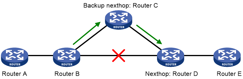
After you configure FRR on Router B as shown in Figure 16, BGP generates a backup next hop Router C for the primary route. BGP uses ARP (for IPv4), echo-mode BFD (for IPv4), or ND (for IPv6) to detect the connectivity to Router D. When the link to Router D fails, BGP directs packets to the backup next hop. At the same time, BGP calculates a new optimal route, and forwards packets over the optimal route.
You can use the following methods to configure BGP FRR:
· Method 1—Execute the pic command in BGP address family view. BGP calculates a backup next hop for each BGP route in the address family if there are two or more unequal-cost routes that reach the destination.
· Method 2—Execute the fast-reroute route-policy command to use a routing policy in which a backup next hop is specified by using the command apply [ ipv6 ] fast-reroute backup-nexthop. The backup next hop calculated by BGP must be the same as the specified backup next hop. Otherwise, BGP does not generate a backup next hop for the primary route. You can also configure if-match clauses in the routing policy to identify the routes protected by FRR.
If both methods are configured, Method 2 takes precedence over Method 1.
BGP supports FRR for IPv4 and IPv6 unicast routes, but not for IPv4 and IPv6 multicast routes.
To configure BGP FRR (IPv4 unicast address family):
|
Step |
Command |
Remarks |
|
1. Enter system view. |
system-view |
N/A |
|
2. Configure the source address of echo packets. |
bfd echo-source-ip ipv4-address |
By default, no source address is specified for echo packets. This step is required when echo-mode BFD is used to detect the connectivity to the next hop of the primary route. Specify a source IP address that does not belong to any local network. For more information about this command, see High Availability Command Reference. |
|
3. Create a routing policy and enter routing policy view. |
route-policy route-policy-name permit node node-number |
By default, no routing policies exist. This step is required when Method 2 is used to enable BGP FRR. For more information about this command, see Layer 3—IP Routing Command Reference. |
|
4. Set the backup next hop for FRR. |
apply fast-reroute backup-nexthop ipv4-address |
By default, no backup next hop is set. This step is required when Method 2 is used to enable BGP FRR. For more information about this command, see Layer 3—IP Routing Command Reference. |
|
5. Return to system view. |
quit |
N/A |
|
6. Enter BGP instance view. |
bgp as-number [ instance instance-name ] |
N/A |
|
7. (Optional.) Use echo-mode BFD to detect the connectivity to the next hop of the primary route. |
primary-path-detect bfd echo |
By default, ARP is used to detect the connectivity to the next hop. |
|
8. (Optional.) Enter BGP-VPN instance view. |
ip vpn-instance vpn-instance-name |
N/A |
|
9. Enter BGP IPv4 unicast address family view or BGP-VPN IPv4 unicast address family view. |
address-family ipv4 [ unicast ] |
N/A |
|
10. Enable BGP FRR. |
· (Method 1) Enable BGP FRR for the address
family: · (Method 2) Apply a routing policy to FRR
for the address family: |
By default, BGP FRR is disabled. Method 1 might result in routing loops. Use it with caution. By default, no routing policy is applied. The apply fast-reroute backup-nexthop and apply ipv6 fast-reroute backup-nexthop commands can take effect in the applied routing policy. Other apply commands do not take effect. |
To configure BGP FRR (IPv6 unicast address family):
|
Step |
Command |
Remarks |
|
1. Enter system view. |
system-view |
N/A |
|
2. Create a routing policy and enter routing policy view. |
route-policy route-policy-name permit node node-number |
By default, no routing policies exist. This step is required when Method 2 is used to enable BGP FRR. For more information about this command, see Layer 3—IP Routing Command Reference. |
|
3. Set the backup next hop for FRR. |
apply ipv6 fast-reroute backup-nexthop ipv6-address |
By default, no backup next hop is set. This step is required when Method 2 is used to enable BGP FRR. For more information about this command, see Layer 3—IP Routing Command Reference. |
|
4. Return to system view. |
quit |
N/A |
|
5. Enter BGP instance view or BGP-VPN instance view. |
· Enter BGP instance view: · Enter BGP-VPN instance view: a. bgp as-number [ instance instance-name ] b. ip vpn-instance vpn-instance-name |
N/A |
|
6. Enter BGP IPv6 unicast address family view or BGP-VPN IPv6 unicast address family view. |
address-family ipv6 [ unicast ] |
N/A |
|
7. Enable BGP FRR. |
· (Method 1) Enable BGP FRR for the address
family: · (Method 2) Apply a routing policy to FRR
for the address family: |
By default, BGP FRR is disabled. Method 1 might result in routing loops. Use it with caution. By default, no routing policy is applied. The apply fast-reroute backup-nexthop and apply ipv6 fast-reroute backup-nexthop commands can take effect in the applied routing policy. Other apply commands do not take effect. |
Configuring 6PE
IPv6 provider edge (6PE) is a transition technology that uses MPLS to connect sparsely populated IPv6 networks through an existing IPv4 backbone network. It is an efficient solution for ISP IPv4/MPLS networks to provide IPv6 traffic switching capability.
Figure 17 Network diagram for 6PE
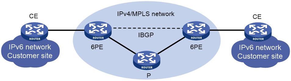
6PE mainly performs the following operations:
· 6PE assigns a label to IPv6 routing information received from a CE router, and sends the labeled IPv6 routing information to the peer 6PE device through an MP-BGP session. The peer 6PE device then forwards the IPv6 routing information to the attached customer site.
· 6PE provides tunnels over the IPv4 backbone so the IPv4 backbone can forward packets for IPv6 networks. The tunnels can be GRE tunnels, MPLS LSPs, or MPLS TE tunnels.
· Upon receiving an IPv6 packet, 6PE adds an inner tag (corresponding to the IPv6 packet) and then an outer tag (corresponding to the public network tunnel) to the IPv6 packet. Devices in the IPv4 backbone network forwards the packet based on the outer tag. When the peer 6PE device receives the packet, it removes the outer and inner tags and forwards the original IPv6 packet to the attached customer site.
To implement exchange of IPv6 routing information, you can configure IPv6 static routing, an IPv6 IGP protocol, or IPv6 BGP between CE and 6PE devices.
For more information about MPLS, MPLS TE, CE, and P, see MPLS Configuration Guide. For more information about GRE, see Layer 3—IP Services Configuration Guide.
Configuring basic 6PE
Before you configure 6PE, perform the following tasks:
· Establish tunnels in the IPv4 backbone network (see Layer 3—IP Services Configuration Guide).
· Configure basic MPLS on 6PE devices (see MPLS Configuration Guide).
· Configure BGP on 6PE devices so that they can advertise tagged IPv6 routing information through BGP sessions. The following describes only BGP configurations on 6PE devices.
To configure basic 6PE:
|
Step |
Command |
Remarks |
|
1. Enter system view. |
system-view |
N/A |
|
2. Enter BGP instance view. |
bgp as-number [ instance instance-name ] |
N/A |
|
3. Specify a 6PE peer or peer group and its AS number. |
peer { group-name | ipv4-address [ mask-length ] } as-number as-number |
No 6PE peer is specified by default. |
|
4. Enter BGP IPv6 unicast address family view. |
address-family ipv6 [ unicast ] |
N/A |
|
5. Enable BGP to exchange IPv6 unicast routing information with the 6PE peer or peer group. |
peer { group-name | ipv4-address [ mask-length ] } enable |
This feature is disabled by default. |
|
6. Enable BGP to exchange labeled IPv6 routes with the 6PE peer or peer group. |
peer { group-name | ipv4-address [ mask-length ] } label-route-capability |
This feature is disabled by default. |
Configuring optional 6PE capabilities
|
Step |
Command |
Remarks |
|
1. Enter system view. |
system-view |
N/A |
|
2. Enter BGP instance view. |
bgp as-number [ instance instance-name ] |
N/A |
|
3. Enter BGP IPv6 unicast address family view. |
address-family ipv6 [ unicast ] |
N/A |
|
4. Advertise COMMUNITY attribute to the 6PE peer or peer group. |
peer { group-name | ipv4-address [ mask-length ] } advertise-community |
By default, the COMMUNITY attribute is not advertised. |
|
5. Advertise extended community attribute to the 6PE peer or peer group. |
peer { group-name | ipv4-address [ mask-length ] } advertise-ext-community |
By default, the extended community attribute is not advertised. |
|
6. Allow the local AS number to appear in routes from the 6PE peer or peer group and specify the repeat times. |
peer { group-name | ipv4-address [ mask-length ] } allow-as-loop [ number ] |
By default, the local AS number is not allowed to appear in routes from the 6PE peer or peer group. |
|
7. Specify an AS path list to filter routes advertised to or received from the 6PE peer or peer group. |
peer { group-name | ipv4-address [ mask-length ] } as-path-acl as-path-acl-number { export | import } |
By default, no AS path list is specified. |
|
8. Specify an IPv6 ACL to filter routes advertised to or received from the 6PE peer or peer group. |
peer { group-name | ipv4-address [ mask-length ] } filter-policy ipv6-acl-number { export | import } |
By default, no ACL is specified. |
|
9. Specify an IPv6 prefix list to filter routes advertised to or received from the 6PE peer or peer group. |
peer { group-name | ipv4-address [ mask-length ] } prefix-list ipv6-prefix-list-name { export | import } |
By default, no IPv6 prefix list is specified. |
|
10. Specify a routing policy to filter routes advertised to or received from the 6PE peer or peer group. |
peer { group-name | ipv4-address [ mask-length ] } route-policy route-policy-name { export | import } |
By default, no routing policy is specified. |
|
11. Advertise a default route to the 6PE peer or peer group. |
peer { group-name | ipv4-address [ mask-length ] } default-route-advertise [ route-policy route-policy-name ] |
By default, no default route is advertised. |
|
12. Save all routes from the 6PE peer or peer group. |
peer { group-name | ipv4-address [ mask-length ] } keep-all-routes |
By default, routes from a peer or peer group are not saved. |
|
13. Configure BGP updates sent to the 6PE peer or peer group to carry only public AS numbers. |
peer { group-name | ipv4-address [ mask-length ] } public-as-only |
By default, BGP updates sent to a 6PE peer or peer group can carry both public and private AS numbers. |
|
14. Specify the maximum number of routes that BGP can receive from the 6PE peer or peer group. |
peer { group-name | ipv4-address [ mask-length ] } route-limit prefix-number [ { alert-only discard | reconnect reconnect-time } | percentage-value ] * |
By default, the number of routes that a router can receive from the 6PE peer or peer group is not limited. |
|
15. Specify a preferred value for routes received from the 6PE peer or peer group. |
peer { group-name | ipv4-address [ mask-length ] } preferred-value value |
By default, the preferred value is 0. |
|
16. Configure the device as a route reflector and the 6PE peer or peer group as a client. |
peer { group-name | ipv4-address [ mask-length ] } reflect-client |
By default, no route reflector or client is configured. |
|
17. Configure the SoO attribute for a peer or peer group. |
peer { group-name | ipv4-address [ mask-length ] } soo site-of-origin |
By default, no SoO attribute is configured for a peer or peer group. |
|
18. Return to user view. |
return |
N/A |
|
19. Display information about the 6PE peer or peer group. |
display bgp [ instance instance-name ] peer ipv6 [ unicast ] [ ipv4-address mask-length | { ipv4-address | group-name group-name } log-info | [ ipv4-address ] verbose ] |
Available in any view. |
|
20. Display routing information advertised to or received from the 6PE peer or peer group. |
display bgp [ instance instance-name ] routing-table ipv6 [ unicast ] peer ipv4-address { advertised-routes | received-routes } [ ipv6-address prefix-length | statistics ] |
Available in any view. |
|
21. Soft-reset a BGP 6PE connection. |
refresh bgp [ instance instance-name ] ipv4-address [ mask-length ] { export | import } ipv6 [ unicast ] |
Available in user view. |
|
22. Reset a BGP 6PE connection. |
reset bgp [ instance instance-name ] ipv4-address [ mask-length ] ipv6 [ unicast ] |
Available in user view. |
Configuring BGP LS
The BGP Link State (LS) feature implements inter-domain and inter-AS advertisement of link state database (LSDB) and TE database (TEDB) information.
The device sends the collected link state information to the controller, which implements end-to-end traffic management and scheduling, and meets the requirements of intended applications.
Configuring basic BGP LS
|
Step |
Command |
Remarks |
|
1. Enter system view. |
system-view |
N/A |
|
2. Enter BGP instance view. |
bgp as-number [ instance instance-name ] |
N/A |
|
3. Specify an AS number for an LS peer or peer group. |
peer { ipv4-address [ mask-length ] | ipv6-address [ prefix-length ] } as-number as-number peer group-name as-number as-number |
By default, no AS number is specified. |
|
4. Create the BGP LS address family and enter its view. |
address-family link-state |
N/A |
|
5. Enable the device to exchange LS information with the peer or peer group. |
peer { group-name | ipv4-address [ mask-length ] | ipv6-address [ prefix-length ] } enable |
By default, the device cannot exchange LS information with the peer or peer group. |
Configuring BGP LS route reflection
Perform this task to configure a BGP route reflector and its clients. The route reflector and its clients automatically form a cluster identified by the router ID of the route reflector. The route reflector forwards route updates among its clients.
To configure BGP LS route reflection:
|
Step |
Command |
Remarks |
|
1. Enter system view. |
system-view |
N/A |
|
2. Enter BGP instance view. |
bgp as-number [ instance instance-name ] |
N/A |
|
3. Enter BGP LS address family view. |
address-family link-state |
N/A |
|
4. Configure the device as a route reflector and specify a peer or peer group as its client. |
peer { group-name | ipv4-address [ mask-length ] | ipv6-address [ prefix-length ] } reflect-client |
By default, no route reflector or client is configured. |
|
5. Enable route reflection between clients. |
reflect between-clients |
By default, route reflection between clients is enabled. |
|
6. (Optional.) Configure the cluster ID of the route reflector. |
reflector cluster-id { cluster-id | ipv4-address } |
By default, a route reflector uses its own router ID as the cluster ID. |
Specifying an AS number and a router ID for BGP LS messages
Perform this task to ensure that LS messages sent by devices in the same AS have the same AS number and router ID.
To specify an AS number and a router ID for BGP LS messages:
|
Step |
Command |
Remarks |
|
1. Enter system view. |
system-view |
N/A |
|
2. Enter BGP instance view. |
bgp as-number [ instance instance-name ] |
N/A |
|
3. Enter BGP LS address family view. |
address-family link-state |
N/A |
|
4. Specify an AS number and a router ID for BGP LS messages. |
domain-distinguisher as-number:router-id |
By default, the AS number and router ID of the current BGP process are used. |
Configuring BMP
The BGP monitoring protocol (BMP) enables a BGP router (BMP client) to send session status information of the specified peers to BMP servers for monitoring. The session status information includes peer relationship establishment and termination as well as routing information. The BMP client communicates with the BMP servers through TCP connections.
To configure BMP:
|
Step |
Command |
Remarks |
|
1. Enter system view. |
system-view |
N/A |
|
2. Create a BMP server and enter BMP server view. |
bmp server server-number |
By default, no BMP servers exist. |
|
3. Configure an IP address and port number for the BMP server. |
server address ipv4-address port port-number |
By default, no IP address and port number are configured for the BMP server. |
|
4. Set the interval at which BGP sends statistics information to the BMP server. |
statistics-interval value |
By default, BGP does not send statistics information to the BMP server. |
|
5. Return to system view. |
quit |
N/A |
|
6. Enter BGP instance view or BGP-VPN instance view. |
· Enter BGP instance view: · Enter BGP-VPN instance view: a. bgp as-number [ instance instance-name ] b. ip vpn-instance vpn-instance-name |
N/A |
|
7. Specify a peer or peer group to be monitored. |
peer { group-name | ipv4-address [ mask-length ] | ipv6-address [ prefix-length ] } bmp server server-number-list |
By default, no peer or peer group is specified. |
Displaying and maintaining BGP
Displaying BGP
Execute display commands in any view (IPv4 unicast address family).
|
Task |
Command |
|
|
Display BGP NSR status information. |
display bgp [ instance instance-name ] non-stop-routing status |
|
|
Display BGP IPv4 unicast peer group information. |
display bgp [ instance instance-name ] group ipv4 [ unicast ] [ vpn-instance vpn-instance-name ] [ group-name group-name ] |
|
|
Display BGP IPv4 unicast peer or peer group information. |
display bgp [ instance instance-name ] peer ipv4 [ unicast ] [ vpn-instance vpn-instance-name ] [ ipv4-address mask-length | { ipv4-address | group-name group-name } log-info | [ ipv4-address ] verbose ] display bgp [ instance instance-name ] peer ipv4 [ unicast ] vpn-instance-all [ verbose ] |
|
|
Display BGP IPv4 unicast routing information. |
display bgp [ instance instance-name ] routing-table ipv4 [ unicast ] [ vpn-instance vpn-instance-name ] [ ipv4-address [ { mask-length | mask } [ longest-match ] ] | ipv4-address [ mask-length | mask ] advertise-info | as-path-acl as-path-acl-number | community-list { { basic-community-list-number | comm-list-name } [ whole-match ] | adv-community-list-number } | peer ipv4-address { advertised-routes | received-routes } [ ipv4-address [ mask-length | mask ] | statistics ] | statistics ] |
|
|
Display dampened BGP IPv4 unicast routing information. |
display bgp [ instance instance-name ] routing-table dampened ipv4 [ unicast ] [ vpn-instance vpn-instance-name ] |
|
|
Display BGP dampening parameter information. |
display bgp [ instance instance-name ] dampening parameter ipv4 [ unicast ] [ vpn-instance vpn-instance-name ] |
|
|
Display BGP IPv4 unicast routing flap statistics. |
display bgp [ instance instance-name ] routing-table flap-info ipv4 [ unicast ] [ vpn-instance vpn-instance-name ] [ ipv4-address [ { mask-length | mask } [ longest-match ] ] | as-path-acl as-path-acl-number ] |
|
|
Display information about routes advertised by the network command and shortcut routes configured by the network short-cut command. |
display bgp [ instance instance-name ] network ipv4 [ unicast ] [ vpn-instance vpn-instance-name ] |
|
|
Display BGP path attribute information. |
display bgp [ instance instance-name ] paths [ as-regular-expression ] |
|
|
Display BGP IPv4 unicast address family update group information. |
display bgp [ instance instance-name ] update-group ipv4 [ unicast ] [ vpn-instance vpn-instance-name ] [ ipv4-address ] |
|
|
Display information about all BGP instances. |
display bgp instance-info |
|
|
Display BMP server information. |
display bgp [ instance instance-name ] bmp server server-number |
|
|
Display ORF prefix information received by a peer. |
display bgp [ instance instance-name ] peer ipv4 [ unicast ] [ vpn-instance vpn-instance-name ] ipv4-address received prefix-list |
|
Execute display commands in any view (IPv6 unicast address family).
|
Task |
Command |
|
|
Display BGP NSR status information. |
display bgp [ instance instance-name ] non-stop-routing status |
|
|
Display BGP IPv6 unicast peer group information. |
display bgp [ instance instance-name ] group ipv6 [ unicast ] [ vpn-instance vpn-instance-name ] [ group-name group-name ] |
|
|
Display BGP IPv6 unicast peer or peer group information. |
display bgp [ instance instance-name ] peer ipv6 [ unicast ] [ vpn-instance vpn-instance-name ] [ ipv6-address prefix-length | { ipv6-address | group-name group-name } log-info | [ ipv6-address ] verbose ] display bgp [ instance instance-name ] peer ipv6 [ unicast ] [ ipv4-address mask-length | ipv4-address log-info | [ ipv4-address ] verbose ] display bgp [ instance instance-name ] peer ipv6 [ unicast ] vpn-instance-all [ verbose ] |
|
|
Display BGP IPv6 unicast routing information. |
display bgp [ instance instance-name ] routing-table ipv6 [ unicast ] [ vpn-instance vpn-instance-name ] [ ipv6-address prefix-length [ advertise-info ] | as-path-acl as-path-acl-number | community-list { { basic-community-list-number | comm-list-name } [ whole-match ] | adv-community-list-number } | peer ipv6-address { advertised-routes | received-routes } [ ipv6-address prefix-length | statistics ] | statistics ] display bgp [ instance instance-name ] routing-table ipv6 [ unicast ] peer ipv4-address { advertised-routes | received-routes } [ ipv6-address prefix-length | statistics ] |
|
|
Display dampened BGP IPv6 unicast routing information. |
display bgp [ instance instance-name ] routing-table dampened ipv6 [ unicast ] [ vpn-instance vpn-instance-name ] |
|
|
Display BGP dampening parameter information. |
display bgp [ instance instance-name ] dampening parameter ipv6 [ unicast ] [ vpn-instance vpn-instance-name ] |
|
|
Display BGP IPv6 unicast routing flap statistics. |
display bgp [ instance instance-name ] routing-table flap-info ipv6 [ unicast ] [ vpn-instance vpn-instance-name ] [ ipv6-address prefix-length | as-path-acl as-path-acl-number ] |
|
|
Display incoming labels for BGP IPv6 unicast routes. |
display bgp [ instance instance-name ] routing-table ipv6 [ unicast ] inlabel |
|
|
Display outgoing labels of BGP IPv6 unicast routes. |
display bgp [ instance instance-name ] routing-table ipv6 [ unicast ] outlabel |
|
|
Display information about routes advertised by the network command and shortcut routes configured by the network short-cut command. |
display bgp [ instance instance-name ] network ipv6 [ unicast ] [ vpn-instance vpn-instance-name ] |
|
|
Display BGP path attribute information. |
display bgp [ instance instance-name ] paths [ as-regular-expression ] |
|
|
Display BGP IPv6 unicast address family update group information. |
display bgp [ instance instance-name ] update-group ipv6 [ unicast ] [ ipv4-address | ipv6-address ] display bgp [ instance instance-name ] update-group ipv6 [ unicast ] vpn-instance vpn-instance-name [ ipv6-address ] |
|
|
Display information about all BGP instances. |
display bgp instance-info |
|
|
Display ORF prefix information received by a peer. |
display bgp [ instance instance-name ] peer ipv6 [ unicast ] [ vpn-instance vpn-instance-name ] ipv6-address received prefix-list display bgp [ instance instance-name ] peer ipv6 [ unicast ] ipv4-address received prefix-list |
|
Execute display commands in any view (IPv4 multicast address family).
|
Task |
Command |
|
|
Display BGP NSR status information. |
display bgp [ instance instance-name ] non-stop-routing status |
|
|
Display BGP IPv4 multicast peer group information. |
display bgp [ instance instance-name ] group ipv4 multicast [ group-name group-name ] |
|
|
Display BGP IPv4 multicast peer or peer group information. |
display bgp [ instance instance-name ] peer ipv4 multicast [ ipv4-address mask-length | { ipv4-address | group-name group-name } log-info | [ ipv4-address ] verbose ] |
|
|
Display BGP IPv4 multicast routing information. |
display bgp [ instance instance-name ] routing-table ipv4 multicast [ ipv4-address [ { mask-length | mask } [ longest-match ] ] | ipv4-address [ mask-length | mask ] advertise-info | as-path-acl as-path-acl-number | community-list { { basic-community-list-number | comm-list-name } [ whole-match ] | adv-community-list-number } | peer ipv4-address { advertised-routes | received-routes } [ ipv4-address [ mask-length | mask ] | statistics ] | statistics ] |
|
|
Display dampened BGP IPv4 multicast routing information. |
display bgp [ instance instance-name ] routing-table dampened ipv4 multicast |
|
|
Display BGP dampening parameter information. |
display bgp [ instance instance-name ] dampening parameter ipv4 multicast |
|
|
Display BGP IPv4 multicast routing flap statistics. |
display bgp [ instance instance-name ] routing-table flap-info ipv4 multicast [ ipv4-address [ { mask-length | mask } [ longest-match ] ] | as-path-acl as-path-acl-number ] |
|
|
Display information about routes advertised by the network command and shortcut routes configured by the network short-cut command. |
display bgp [ instance instance-name ] network ipv4 multicast |
|
|
Display BGP path attribute information. |
display bgp [ instance instance-name ] paths [ as-regular-expression ] |
|
|
Display BGP IPv4 multicast address family update group information. |
display bgp [ instance instance-name ] update-group ipv4 multicast [ ipv4-address ] |
|
|
Display information about all BGP instances. |
display bgp instance-info |
|
|
Display BMP server information. |
display bgp [ instance instance-name ] bmp server server-number |
|
|
Display ORF prefix information received by a peer. |
display bgp [ instance instance-name ] peer ipv4 multicast ipv4-address received prefix-list |
|
Execute display commands in any view (IPv6 multicast address family).
|
Task |
Command |
|
Display BGP NSR status information. |
display bgp [ instance instance-name ] non-stop-routing status |
|
Display BGP IPv6 multicast peer group information. |
display bgp [ instance instance-name ] group ipv6 multicast [ group-name group-name ] |
|
Display BGP IPv6 multicast peer or peer group information. |
display bgp [ instance instance-name ] peer ipv6 multicast [ ipv6-address prefix-length | { ipv6-address | group-name group-name } log-info | [ ipv6-address ] verbose ] |
|
Display BGP IPv6 multicast routing information. |
display bgp [ instance instance-name ] routing-table ipv6 multicast [ ipv6-address prefix-length [ advertise-info ] | as-path-acl as-path-acl-number | community-list { { basic-community-list-number | comm-list-name } [ whole-match ] | adv-community-list-number } | peer ipv6-address { advertised-routes | received-routes } [ ipv6-address prefix-length | statistics ] | statistics ] |
|
Display dampened BGP IPv6 multicast routing information. |
display bgp [ instance instance-name ] routing-table dampened ipv6 multicast |
|
Display BGP dampening parameter information. |
display bgp [ instance instance-name ] dampening parameter ipv6 multicast |
|
Display BGP IPv6 multicast routing flap statistics. |
display bgp [ instance instance-name ] routing-table flap-info ipv6 multicast [ ipv6-address prefix-length | as-path-acl as-path-acl-number ] |
|
Display information about routes advertised by the network command and shortcut routes configured by the network short-cut command. |
display bgp [ instance instance-name ] network ipv6 multicast |
|
Display BGP path attribute information. |
display bgp [ instance instance-name ] paths [ as-regular-expression ] |
|
Display BGP IPv6 multicast address family update group information. |
display bgp [ instance instance-name ] update-group ipv6 multicast [ ipv6-address ] |
|
Display information about all BGP instances. |
display bgp instance-info |
|
Display ORF prefix information received by a peer. |
display bgp [ instance instance-name ] peer ipv6 multicast ipv6-address received prefix-list |
Execute display commands in any view (LS address family).
|
Task |
Command |
|
Display BGP LS peer group information. |
display bgp [ instance instance-name ] group link-state [ group-name group-name ] |
|
Display BGP LS information. |
display bgp [ instance instance-name ] link-state [ ls-prefix | peer { ipv4-address | ipv6-address } { advertised | received } [ statistics ] | statistics ] |
|
Display BGP LS peer or peer group information. |
display bgp [ instance instance-name ] peer link-state [ ipv4-address mask-length | ipv6-address prefix-length | { ipv4-address | ipv6-address | group-name group-name } log-info | [ ipv4-address | ipv6-address ] verbose ] |
|
Display BGP LS address family update group information. |
display bgp [ instance instance-name ] update-group link-state [ ipv4-address | ipv6-address ] |
Execute display commands in any view (IPv4 RT filter address family).
|
Task |
Command |
|
Display BGP IPv4 RT filter information. |
display bgp [ instance instance-name ] ipv4 rtfilter [ peer ipv4-address [ statistics ] | statistics ] |
|
Display BGP IPv4 RT filter routing information. |
display bgp [ instance instance-name ] routing-table ipv4 rtfilter [ default-rt [ advertise-info ] | [ origin-as as-number ] [ route-target [ advertise-info ] ] | peer ipv4-address { advertised-routes | received-routes } [ default-rt | [ origin-as as-number ] [ route-target ] | statistics ] | statistics ] |
Resetting BGP sessions
Execute reset commands in user view.
|
Task |
Command |
|
Reset all BGP sessions. |
reset bgp [ instance instance-name ] all |
|
Reset BGP sessions for IPv4 unicast address family. |
reset bgp [ instance instance-name ] { as-number | ipv4-address [ mask-length ] | all | external | group group-name | internal } ipv4 [ unicast ] [ vpn-instance vpn-instance-name ] |
|
Reset BGP sessions for IPv6 unicast address family. |
reset bgp [ instance instance-name ] { as-number | ipv6-address [ prefix-length ] | all | external | group group-name | internal } ipv6 [ unicast ] [ vpn-instance vpn-instance-name ] reset bgp [ instance instance-name ] ipv4-address [ mask-length ] ipv6 [ unicast ] |
|
Reset BGP sessions for LS address family. |
reset bgp [ instance instance-name ] { as-number | ipv4-address [ mask-length ] | ipv6-address [ prefix-length ] | all | external | group group-name | internal } link-state |
|
Reset BGP sessions for IPv4 multicast address family. |
reset bgp [ instance instance-name ] { as-number | ipv4-address [ mask-length ] | all | external | group group-name | internal } ipv4 multicast |
|
Reset BGP sessions for IPv6 multicast address family. |
reset bgp [ instance instance-name ] { as-number | ipv6-address [ prefix-length ] | all | external | group group-name | internal } ipv6 multicast |
Clearing BGP information
Execute reset commands in user view.
|
Task |
Command |
|
Clear dampening information for BGP IPv4 unicast routes and release suppressed BGP IPv4 unicast routes. |
reset bgp [ instance instance-name ] dampening ipv4 [ unicast ] [ vpn-instance vpn-instance-name ] [ ipv4-address [ mask-length | mask ] ] |
|
Clear flap information for BGP IPv4 unicast routes. |
reset bgp [ instance instance-name ] flap-info ipv4 [ unicast ] [ vpn-instance vpn-instance-name ] [ ipv4-address [ mask-length | mask ] | as-path-acl as-path-acl-number | peer ipv4-address [ mask-length ] ] |
|
Clear dampening information for BGP IPv6 unicast routes and release suppressed BGP IPv6 unicast routes. |
reset bgp [ instance instance-name ] dampening ipv6 [ unicast ] [ vpn-instance vpn-instance-name ] [ ipv6-address prefix-length ] |
|
Clear flap information for BGP IPv6 unicast routes. |
reset bgp [ instance instance-name ] flap-info ipv6 [ unicast ] [ vpn-instance vpn-instance-name ] [ ipv6-address prefix-length | as-path-acl as-path-acl-number | peer ipv6-address [ prefix-length ] ] |
|
Clear dampening information for BGP IPv4 multicast routes and release suppressed BGP IPv4 multicast routes. |
reset bgp [ instance instance-name ] dampening ipv4 multicast [ ipv4-address [ mask-length | mask] ] |
|
Clear flap information for BGP IPv4 multicast routes. |
reset bgp [ instance instance-name ] flap-info ipv4 multicast [ ipv4-address [ mask-length | mask ] | as-path-acl as-path-acl-number | peer ipv4-address [ mask-length ] ] |
|
Clear dampening information for BGP IPv6 multicast routes and release suppressed BGP IPv6 multicast routes. |
reset bgp [ instance instance-name ] dampening ipv6 multicast [ ipv6-address prefix-length ] |
|
Clear flap information for BGP IPv6 multicast routes. |
reset bgp [ instance instance-name ] flap-info ipv6 multicast [ ipv6-address prefix-length | as-path-acl as-path-acl-number | peer ipv6-address [ prefix-length ] ] |
|
Clear BMP server statistics. |
reset bgp [ instance instance-name ] bmp server server-number statistics |
IPv4 BGP configuration examples
Basic BGP configuration example
Network requirements
As shown in Figure 18, all switches run BGP. Run EBGP between Switch A and Switch B, and run IBGP between Switch B and Switch C to allow Switch C to access network 8.1.1.0/24 connected to Switch A.
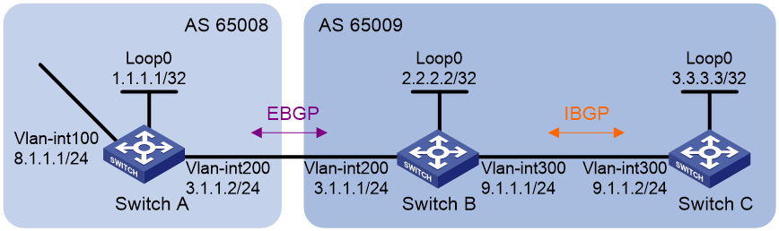
Requirements analysis
To prevent route flapping caused by port state changes, this example uses loopback interfaces to establish IBGP connections. Loopback interfaces are virtual interfaces. Therefore, use the peer connect-interface command to specify the loopback interface as the source interface for establishing BGP connections. Enable OSPF in AS 65009 to ensure that Switch B can communicate with Switch C through loopback interfaces.
The EBGP peers, Switch A and Switch B (usually belong to different carriers), are located in different ASs. Typically, their loopback interfaces are not reachable to each other, so directly connected interfaces are used for establishing EBGP sessions. To enable Switch C to access the network 8.1.1.0/24 connected directly to Switch A, inject network 8.1.1.0/24 to the BGP routing table of Switch A.
Configuration procedure
1. Configure IP addresses for interfaces. (Details not shown.)
2. Configure IBGP:
# Configure Switch B.
<SwitchB> system-view
[SwitchB] bgp 65009
[SwitchB-bgp-default] router-id 2.2.2.2
[SwitchB-bgp-default] peer 3.3.3.3 as-number 65009
[SwitchB-bgp-default] peer 3.3.3.3 connect-interface loopback 0
[SwitchB-bgp-default] address-family ipv4 unicast
[SwitchB-bgp-default-ipv4] peer 3.3.3.3 enable
[SwitchB-bgp-default-ipv4] quit
[SwitchB-bgp-default] quit
[SwitchB] ospf 1
[SwitchB-ospf-1] area 0
[SwitchB-ospf-1-area-0.0.0.0] network 2.2.2.2 0.0.0.0
[SwitchB-ospf-1-area-0.0.0.0] network 9.1.1.0 0.0.0.255
[SwitchB-ospf-1-area-0.0.0.0] quit
[SwitchB-ospf-1] quit
# Configure Switch C.
<SwitchC> system-view
[SwitchC] bgp 65009
[SwitchC-bgp-default] router-id 3.3.3.3
[SwitchC-bgp-default] peer 2.2.2.2 as-number 65009
[SwitchC-bgp-default] peer 2.2.2.2 connect-interface loopback 0
[SwitchC-bgp-default] address-family ipv4 unicast
[SwitchC-bgp-default-ipv4] peer 2.2.2.2 enable
[SwitchC-bgp-default-ipv4] quit
[SwitchC-bgp-default] quit
[SwitchC] ospf 1
[SwitchC-ospf-1] area 0
[SwitchC-ospf-1-area-0.0.0.0] network 3.3.3.3 0.0.0.0
[SwitchC-ospf-1-area-0.0.0.0] network 9.1.1.0 0.0.0.255
[SwitchC-ospf-1-area-0.0.0.0] quit
[SwitchC-ospf-1] quit
[SwitchC] display bgp peer ipv4
BGP local router ID : 3.3.3.3
Local AS number : 65009
Total number of peers : 1 Peers in established state : 1
* - Dynamically created peer
Peer AS MsgRcvd MsgSent OutQ PrefRcv Up/Down State
2.2.2.2 65009 2 2 0 0 00:00:13 Established
The output shows that Switch C has established an IBGP peer relationship with Switch B.
3. Configure EBGP:
# Configure Switch A.
<SwitchA> system-view
[SwitchA] bgp 65008
[SwitchA-bgp-default] router-id 1.1.1.1
[SwitchA-bgp-default] peer 3.1.1.1 as-number 65009
[SwitchA-bgp-default] address-family ipv4 unicast
[SwitchA-bgp-default-ipv4] peer 3.1.1.1 enable
[SwitchA-bgp-default-ipv4] network 8.1.1.0 24
[SwitchA-bgp-default-ipv4] quit
[SwitchA-bgp-default] quit
# Configure Switch B.
[SwitchB] bgp 65009
[SwitchB-bgp-default] peer 3.1.1.2 as-number 65008
[SwitchB-bgp-default] address-family ipv4 unicast
[SwitchB-bgp-default-ipv4] peer 3.1.1.2 enable
[SwitchB-bgp-default-ipv4] quit
[SwitchB-bgp-default] quit
# Display BGP peer information on Switch B.
[SwitchB] display bgp peer ipv4
BGP local router ID : 2.2.2.2
Local AS number : 65009
Total number of peers : 2 Peers in established state : 2
* - Dynamically created peer
Peer AS MsgRcvd MsgSent OutQ PrefRcv Up/Down State
3.3.3.3 65009 4 4 0 0 00:02:49 Established
3.1.1.2 65008 2 2 0 0 00:00:05 Established
The output shows that Switch B has established an IBGP peer relationship with Switch C and an EBGP peer relationship with Switch A.
# Display the BGP routing table on Switch A.
[SwitchA] display bgp routing-table ipv4
Total number of routes: 1
BGP local router ID is 1.1.1.1
Status codes: * - valid, > - best, d - dampened, h - history,
s - suppressed, S - stale, i - internal, e - external
a – additional-path
Origin: i - IGP, e - EGP, ? - incomplete
Network NextHop MED LocPrf PrefVal Path/Ogn
* > 8.1.1.0/24 8.1.1.1 0 32768 i
# Display the BGP routing table on Switch B.
[SwitchB] display bgp routing-table ipv4
Total number of routes: 1
BGP local router ID is 2.2.2.2
Status codes: * - valid, > - best, d - dampened, h - history,
s - suppressed, S - stale, i - internal, e - external
a – additional-path
Origin: i - IGP, e - EGP, ? - incomplete
Network NextHop MED LocPrf PrefVal Path/Ogn
* >e 8.1.1.0/24 3.1.1.2 0 0 65008i
# Display the BGP routing table on Switch C.
[SwitchC] display bgp routing-table ipv4
Total number of routes: 1
BGP local router ID is 3.3.3.3
Status codes: * - valid, > - best, d - dampened, h - history,
s - suppressed, S - stale, i - internal, e - external
a – additional-path
Origin: i - IGP, e - EGP, ? - incomplete
Network NextHop MED LocPrf PrefVal Path/Ogn
i 8.1.1.0/24 3.1.1.2 0 100 0 65008i
The outputs show that Switch A has learned no route to AS 65009, and Switch C has learned network 8.1.1.0, but the next hop 3.1.1.2 is unreachable. As a result, the route is invalid.
4. Redistribute direct routes:
Configure BGP to redistribute direct routes on Switch B, so that Switch A can obtain the route to 9.1.1.0/24, and Switch C can obtain the route to 3.1.1.0/24.
# Configure Switch B.
[SwitchB] bgp 65009
[SwitchB-bgp-default] address-family ipv4 unicast
[SwitchB-bgp-default-ipv4] import-route direct
[SwitchB-bgp-default-ipv4] quit
[SwitchB-bgp-default] quit
# Display the BGP routing table on Switch A.
[SwitchA] display bgp routing-table ipv4
Total number of routes: 4
BGP local router ID is 1.1.1.1
Status codes: * - valid, > - best, d - dampened, h - history,
s - suppressed, S - stale, i - internal, e - external
a – additional-path
Origin: i - IGP, e - EGP, ? - incomplete
Network NextHop MED LocPrf PrefVal Path/Ogn
* >e 2.2.2.2/32 3.1.1.1 0 0 65009?
* >e 3.1.1.0/24 3.1.1.1 0 0 65009?
* > 8.1.1.0/24 8.1.1.1 0 32768 i
* >e 9.1.1.0/24 3.1.1.1 0 0 65009?
Two routes, 2.2.2.2/32 and 9.1.1.0/24, have been added in Switch A's routing table.
# Display the BGP routing table on Switch C.
[SwitchC] display bgp routing-table ipv4
Total number of routes: 4
BGP local router ID is 3.3.3.3
Status codes: * - valid, > - best, d - dampened, h - history,
s - suppressed, S - stale, i - internal, e - external
a – additional-path
Origin: i - IGP, e - EGP, ? - incomplete
Network NextHop MED LocPrf PrefVal Path/Ogn
* >i 2.2.2.2/32 2.2.2.2 0 100 0 ?
* >i 3.1.1.0/24 2.2.2.2 0 100 0 ?
* >i 8.1.1.0/24 3.1.1.2 0 100 0 65008i
* >i 9.1.1.0/24 2.2.2.2 0 100 0 ?
The output shows that the route 8.1.1.0 becomes valid with the next hop as Switch A.
Verifying the configuration
# Verify that Switch C can ping 8.1.1.1.
[SwitchC] ping 8.1.1.1
Ping 8.1.1.1 (8.1.1.1): 56 data bytes, press CTRL_C to break
56 bytes from 8.1.1.1: icmp_seq=0 ttl=254 time=10.000 ms
56 bytes from 8.1.1.1: icmp_seq=1 ttl=254 time=4.000 ms
56 bytes from 8.1.1.1: icmp_seq=2 ttl=254 time=4.000 ms
56 bytes from 8.1.1.1: icmp_seq=3 ttl=254 time=3.000 ms
56 bytes from 8.1.1.1: icmp_seq=4 ttl=254 time=3.000 ms
--- Ping statistics for 8.1.1.1 ---
5 packet(s) transmitted, 5 packet(s) received, 0.0% packet loss
round-trip min/avg/max/std-dev = 3.000/4.800/10.000/2.638 ms
BGP and IGP route redistribution configuration example
Network requirements
As shown in Figure 19, all devices of company A belong to AS 65008, and all devices of company B belong to AS 65009.
Configure BGP and IGP route redistribution to allow Switch A to access network 9.1.2.0/24 in AS 65009, and Switch C to access network 8.1.1.0/24 in AS 65008.
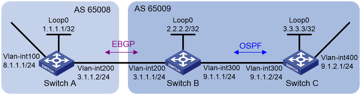
Configuration considerations
Configure BGP to redistribute routes from OSPF on Switch B, so Switch A can obtain the route to 9.1.2.0/24. Configure OSPF to redistribute routes from BGP on Switch B, so Switch C can obtain the route to 8.1.1.0/24.
Configuration procedure
1. Configure IP addresses for interfaces. (Details not shown.)
2. Configure OSPF:
Enable OSPF in AS 65009, so Switch B can obtain the route to 9.1.2.0/24.
# Configure Switch B.
<SwitchB> system-view
[SwitchB] ospf 1
[SwitchB-ospf-1] area 0
[SwitchB-ospf-1-area-0.0.0.0] network 2.2.2.2 0.0.0.0
[SwitchB-ospf-1-area-0.0.0.0] network 9.1.1.0 0.0.0.255
[SwitchB-ospf-1-area-0.0.0.0] quit
[SwitchB-ospf-1] quit
# Configure Switch C.
<SwitchC> system-view
[SwitchC] ospf 1
[SwitchC-ospf-1] import-route direct
[SwitchC-ospf-1] area 0
[SwitchC-ospf-1-area-0.0.0.0] network 9.1.1.0 0.0.0.255
[SwitchC-ospf-1-area-0.0.0.0] quit
[SwitchC-ospf-1] quit
3. Configure the EBGP connection:
Configure the EBGP connection and inject network 8.1.1.0/24 to the BGP routing table of Switch A, so that Switch B can obtain the route to 8.1.1.0/24.
# Configure Switch A.
<SwitchA> system-view
[SwitchA] bgp 65008
[SwitchA-bgp-default] router-id 1.1.1.1
[SwitchA-bgp-default] peer 3.1.1.1 as-number 65009
[SwitchA-bgp-default] address-family ipv4 unicast
[SwitchA-bgp-default-ipv4] peer 3.1.1.1 enable
[SwitchA-bgp-default-ipv4] network 8.1.1.0 24
[SwitchA-bgp-default-ipv4] quit
[SwitchA-bgp-default] quit
# Configure Switch B.
[SwitchB] bgp 65009
[SwitchB-bgp-default] router-id 2.2.2.2
[SwitchB-bgp-default] peer 3.1.1.2 as-number 65008
[SwitchB-bgp-default] address-family ipv4 unicast
[SwitchB-bgp-default-ipv4] peer 3.1.1.2 enable
4. Configure BGP and IGP route redistribution:
# Configure route redistribution between BGP and OSPF on Switch B.
[SwitchB-bgp-default-ipv4] import-route ospf 1
[SwitchB-bgp-default-ipv4] quit
[SwitchB-bgp-default] quit
[SwitchB] ospf 1
[SwitchB-ospf-1] import-route bgp
[SwitchB-ospf-1] quit
# Display the BGP routing table on Switch A.
[SwitchA] display bgp routing-table ipv4
Total number of routes: 3
BGP local router ID is 1.1.1.1
Status codes: * - valid, > - best, d - dampened, h - history,
s - suppressed, S - stale, i - internal, e - external
a – additional-path
Origin: i - IGP, e - EGP, ? - incomplete
Network NextHop MED LocPrf PrefVal Path/Ogn
* >e 3.3.3.3/32 3.1.1.1 1 0 65009?
* > 8.1.1.0/24 8.1.1.1 0 32768 i
* >e 9.1.2.0/24 3.1.1.1 1 0 65009?
# Display the OSPF routing table on Switch C.
[SwitchC] display ospf routing
OSPF Process 1 with Router ID 3.3.3.3
Routing Tables
Routing for Network
Destination Cost Type NextHop AdvRouter Area
9.1.1.0/24 1 Transit 9.1.1.2 3.3.3.3 0.0.0.0
2.2.2.2/32 1 Stub 9.1.1.1 2.2.2.2 0.0.0.0
Routing for ASEs
Destination Cost Type Tag NextHop AdvRouter
8.1.1.0/24 1 Type2 1 9.1.1.1 2.2.2.2
Total Nets: 3
Intra Area: 2 Inter Area: 0 ASE: 1 NSSA: 0
Verifying the configuration
# Use ping for verification.
[SwitchA] ping -a 8.1.1.1 9.1.2.1
Ping 9.1.2.1 (9.1.2.1) from 8.1.1.1: 56 data bytes, press CTRL_C to break
56 bytes from 9.1.2.1: icmp_seq=0 ttl=254 time=10.000 ms
56 bytes from 9.1.2.1: icmp_seq=1 ttl=254 time=12.000 ms
56 bytes from 9.1.2.1: icmp_seq=2 ttl=254 time=2.000 ms
56 bytes from 9.1.2.1: icmp_seq=3 ttl=254 time=7.000 ms
56 bytes from 9.1.2.1: icmp_seq=4 ttl=254 time=9.000 ms
--- Ping statistics for 9.1.2.1 ---
5 packet(s) transmitted, 5 packet(s) received, 0.0% packet loss
round-trip min/avg/max/std-dev = 2.000/8.000/12.000/3.406 ms
[SwitchC] ping -a 9.1.2.1 8.1.1.1
Ping 8.1.1.1 (8.1.1.1) from 9.1.2.1: 56 data bytes, press CTRL_C to break
56 bytes from 8.1.1.1: icmp_seq=0 ttl=254 time=9.000 ms
56 bytes from 8.1.1.1: icmp_seq=1 ttl=254 time=4.000 ms
56 bytes from 8.1.1.1: icmp_seq=2 ttl=254 time=3.000 ms
56 bytes from 8.1.1.1: icmp_seq=3 ttl=254 time=3.000 ms
56 bytes from 8.1.1.1: icmp_seq=4 ttl=254 time=3.000 ms
--- Ping statistics for 8.1.1.1 ---
5 packet(s) transmitted, 5 packet(s) received, 0.0% packet loss
round-trip min/avg/max/std-dev = 3.000/4.400/9.000/2.332 ms
BGP route summarization configuration example
Network requirements
As shown in Figure 20, run EBGP between Switch C and Switch D, so the internal network and external network can communicate with each other.
· In AS 65106, perform the following configurations so the devices in the internal network can communicate:
¡ Configure static routing between Switch A and Switch B.
¡ Configure OSPF between Switch B and Switch C.
¡ Configure OSPF to redistribute static routes.
· Configure route summarization on Switch C so BGP advertises a summary route instead of advertising routes to the 192.168.64.0/24, 192.168.74.0/24, and 192.168.99.0/24 networks to Switch D.
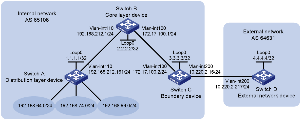
Configuration procedure
1. Configure IP addresses for interfaces. (Details not shown.)
2. Configure static routing between Switch A and Switch B:
# Configure a default route with the next hop 192.168.212.1 on Switch A.
<SwitchA> system-view
[SwitchA] ip route-static 0.0.0.0 0 192.168.212.1
# Configure static routes to 192.168.64.0/24, 192.168.74.0/24, and 192.168.99.0/24 with the same next hop 192.168.212.161 on Switch B.
<SwitchB> system-view
[SwitchB] ip route-static 192.168.64.0 24 192.168.212.161
[SwitchB] ip route-static 192.168.74.0 24 192.168.212.161
[SwitchB] ip route-static 192.168.99.0 24 192.168.212.161
3. Configure OSPF between Switch B and Switch C and configure OSPF on Switch B to redistribute static routes:
# Configure OSPF to advertise the local network and enable OSPF to redistribute static routes on Switch B.
[SwitchB] ospf
[SwitchB-ospf-1] area 0
[SwitchB-ospf-1-area-0.0.0.0] network 172.17.100.0 0.0.0.255
[SwitchB-ospf-1-area-0.0.0.0] quit
[SwitchB-ospf-1] import-route static
[SwitchB-ospf-1] quit
# Configure OSPF to advertise the local networks on Switch C.
[SwitchC] ospf
[SwitchC-ospf-1] area 0
[SwitchC-ospf-1-area-0.0.0.0] network 172.17.100.0 0.0.0.255
[SwitchC-ospf-1-area-0.0.0.0] network 10.220.2.0 0.0.0.255
[SwitchC-ospf-1-area-0.0.0.0] quit
[SwitchC-ospf-1] quit
# Display the IP routing table on Switch C.
[SwitchC] display ip routing-table protocol ospf
Summary count : 5
OSPF Routing table Status : <Active>
Summary count : 3
Destination/Mask Proto Pre Cost NextHop Interface
192.168.64.0/24 OSPF 150 1 172.17.100.1 Vlan100
192.168.74.0/24 OSPF 150 1 172.17.100.1 Vlan100
192.168.99.0/24 OSPF 150 1 172.17.100.1 Vlan100
OSPF Routing table Status : <Inactive>
Summary count : 2
Destination/Mask Proto Pre Cost NextHop Interface
10.220.2.0/24 OSPF 10 1 10.220.2.16 Vlan200
172.17.100.0/24 OSPF 10 1 172.17.100.2 Vlan100
The output shows that Switch C has learned routes to 192.168.64.0/24, 192.168.99.0/24, and 192.168.64.0/18 through OSPF.
4. Configure BGP between Switch C and Switch D and configure BGP on Switch C to redistribute OSPF routes:
# On Switch C, enable BGP, specify Switch D as an EBGP peer, and configure BGP to redistribute OSPF routes.
[SwitchC] bgp 65106
[SwitchC-bgp-default] router-id 3.3.3.3
[SwitchC-bgp-default] peer 10.220.2.217 as-number 64631
[SwitchC-bgp-default] address-family ipv4 unicast
[SwitchC-bgp-default-ipv4] peer 10.220.2.217 enable
[SwitchC-bgp-default-ipv4] import-route ospf
# Enable BGP, and configure Switch C as an EBGP peer on Switch D.
[SwitchD] bgp 64631
[SwitchD-bgp-default] router-id 4.4.4.4
[SwitchD-bgp-default] peer 10.220.2.16 as-number 65106
[SwitchD-bgp-default] address-family ipv4 unicast
[SwitchD-bgp-default-ipv4] peer 10.220.2.16 enable
[SwitchD-bgp-default-ipv4] quit
[SwitchD-bgp-default] quit
# Display the IP routing table on Switch D.
[SwitchD] display ip routing-table protocol bgp
Summary count : 3
BGP Routing table Status : <Active>
Summary count : 3
Destination/Mask Proto Pre Cost NextHop Interface
192.168.64.0/24 BGP 255 1 10.220.2.16 Vlan200
192.168.74.0/24 BGP 255 1 10.220.2.16 Vlan200
192.168.99.0/24 BGP 255 1 10.220.2.16 Vlan200
BGP Routing table Status : <Inactive>
Summary count : 0
The output shows that Switch D has learned routes to 192.168.64.0/24, 192.168.74.0/24, and 192.168.99.0/24 through BGP.
# Verify that Switch D can ping hosts on networks 192.168.74.0/24, 192.168.99.0/24, and 192.168.64.0/18. (Details not shown.)
5. Configure route summarization on Switch C to summarize 192.168.64.0/24, 192.168.74.0/24, and 192.168.99.0/24 into a single route 192.168.64.0/18, and disable advertisement of specific routes.
[SwitchC-bgp-default-ipv4] aggregate 192.168.64.0 18 detail-suppressed
[SwitchC-bgp-default-ipv4] quit
[SwitchC-bgp-default] quit
Verifying the configuration
# Display IP routing table on Switch C.
[SwitchC] display ip routing-table | include 192.168
192.168.64.0/18 BGP 130 0 127.0.0.1 NULL0
192.168.64.0/24 OSPF 150 1 172.17.100.1 Vlan100
192.168.74.0/24 OSPF 150 1 172.17.100.1 Vlan100
192.168.99.0/24 OSPF 150 1 172.17.100.1 Vlan100
The output shows that Switch C has a summary route 192.168.64.0/18 with the output interface Null0.
# Display IP routing table on Switch D.
[SwitchD] display ip routing-table protocol bgp
Summary count : 1
BGP Routing table Status : <Active>
Summary count : 1
Destination/Mask Proto Pre Cost NextHop Interface
192.168.64.0/18 BGP 255 0 10.220.2.16 Vlan200
BGP Routing table Status : <Inactive>
Summary count : 0
The output shows that Switch D has only one route 192.168.64.0/18 to AS 65106.
# Verify that Switch D can ping the hosts on networks 192.168.64.0/24, 192.168.74.0/24, and 192.168.99.0/24. (Details not shown.)
BGP load balancing configuration example
Network requirements
As shown in Figure 21, run EBGP between Switch A and Switch B, and between Switch A and Switch C. Run IBGP between Switch B and Switch C. Configure load balancing over the two EBGP links on Switch A.
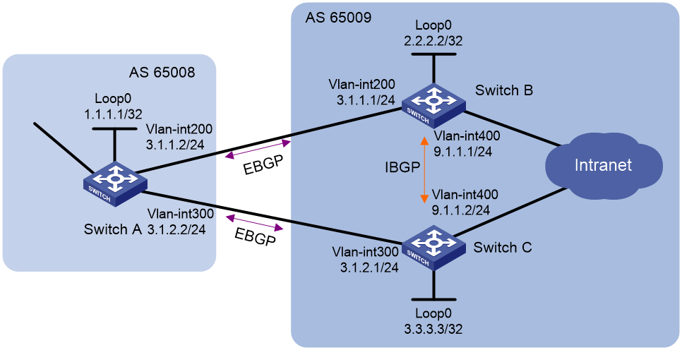
Configuration considerations
On Switch A:
· Establish EBGP connections with Switch B and Switch C.
· Configure BGP to advertise network 8.1.1.0/24 to Switch B and Switch C, so that Switch B and Switch C can access the internal network connected to Switch A.
On Switch B:
· Establish an EBGP connection with Switch A and an IBGP connection with Switch C.
· Configure BGP to advertise network 9.1.1.0/24 to Switch A, so that Switch A can access the intranet through Switch B.
· Configure a static route to interface loopback 0 on Switch C (or use a routing protocol like OSPF) to establish the IBGP connection.
On Switch C:
· Establish an EBGP connection with Switch A and an IBGP connection with Switch B.
· Configure BGP to advertise network 9.1.1.0/24 to Switch A, so that Switch A can access the intranet through Switch C.
· Configure a static route to interface loopback 0 on Switch B (or use another protocol like OSPF) to establish the IBGP connection.
Configure load balancing on Switch A.
Configuration procedure
1. Configure IP addresses for interfaces. (Details not shown.)
2. Configure BGP connections:
# Configure Switch A.
<SwitchA> system-view
[SwitchA] bgp 65008
[SwitchA-bgp-default] router-id 1.1.1.1
[SwitchA-bgp-default] peer 3.1.1.1 as-number 65009
[SwitchA-bgp-default] peer 3.1.2.1 as-number 65009
[SwitchA-bgp-default] address-family ipv4 unicast
[SwitchA-bgp-default-ipv4] peer 3.1.1.1 enable
[SwitchA-bgp-default-ipv4] peer 3.1.2.1 enable
[SwitchA-bgp-default-ipv4] network 8.1.1.0 24
[SwitchA-bgp-default-ipv4] quit
[SwitchA-bgp-default] quit
# Configure Switch B.
<SwitchB> system-view
[SwitchB] bgp 65009
[SwitchB-bgp-default] router-id 2.2.2.2
[SwitchB-bgp-default] peer 3.1.1.2 as-number 65008
[SwitchB-bgp-default] peer 3.3.3.3 as-number 65009
[SwitchB-bgp-default] peer 3.3.3.3 connect-interface loopback 0
[SwitchB-bgp-default] address-family ipv4 unicast
[SwitchB-bgp-default-ipv4] peer 3.1.1.2 enable
[SwitchB-bgp-default-ipv4] peer 3.3.3.3 enable
[SwitchB-bgp-default-ipv4] network 9.1.1.0 24
[SwitchB-bgp-default-ipv4] quit
[SwitchB-bgp-default] quit
[SwitchB] ip route-static 3.3.3.3 32 9.1.1.2
# Configure Switch C.
<SwitchC> system-view
[SwitchC] bgp 65009
[SwitchC-bgp-default] router-id 3.3.3.3
[SwitchC-bgp-default] peer 3.1.2.2 as-number 65008
[SwitchC-bgp-default] peer 2.2.2.2 as-number 65009
[SwitchC-bgp-default] peer 2.2.2.2 connect-interface loopback 0
[SwitchC-bgp-default] address-family ipv4 unicast
[SwitchC-bgp-default-ipv4] peer 3.1.2.2 enable
[SwitchC-bgp-default-ipv4] peer 2.2.2.2 enable
[SwitchC-bgp-default-ipv4] network 9.1.1.0 24
[SwitchC-bgp-default-ipv4] quit
[SwitchC-bgp-default] quit
[SwitchC] ip route-static 2.2.2.2 32 9.1.1.1
# Display the BGP routing table on Switch A.
[SwitchA] display bgp routing-table ipv4
Total number of routes: 3
BGP local router ID is 1.1.1.1
Status codes: * - valid, > - best, d - dampened, h - history,
s - suppressed, S - stale, i - internal, e - external
a – additional-path
Origin: i - IGP, e - EGP, ? - incomplete
Network NextHop MED LocPrf PrefVal Path/Ogn
* > 8.1.1.0/24 8.1.1.1 0 32768 i
* >e 9.1.1.0/24 3.1.1.1 0 0 65009i
* e 3.1.2.1 0 0 65009i
¡ The output shows two valid routes to destination 9.1.1.0/24. The route with next hop 3.1.1.1 is marked with a greater-than sign (>), indicating that it is the optimal route (because the ID of Switch B is smaller). The route with next hop 3.1.2.1 is marked with an asterisk (*), indicating that it is a valid route, but not the optimal route.
¡ By using the display ip routing-table command, you can find only one route to 9.1.1.0/24 with next hop 3.1.1.1 and output interface VLAN-interface 200.
3. Configure loading balancing:
Because Switch A has two routes to reach AS 65009, configuring load balancing over the two BGP routes on Switch A can improve link usage.
# Configure Switch A.
[SwitchA] bgp 65008
[SwitchA-bgp-default] address-family ipv4 unicast
[SwitchA-bgp-default-ipv4] balance 2
[SwitchA-bgp-default-ipv4] quit
[SwitchA-bgp-default] quit
Verifying the configuration
# Display the BGP routing table on Switch A.
[SwitchA] display bgp routing-table ipv4
Total number of routes: 3
BGP local router ID is 1.1.1.1
Status codes: * - valid, > - best, d - dampened, h - history,
s - suppressed, S - stale, i - internal, e - external
a – additional-path
Origin: i - IGP, e - EGP, ? - incomplete
Network NextHop MED LocPrf PrefVal Path/Ogn
* > 8.1.1.0/24 8.1.1.1 0 32768 i
* >e 9.1.1.0/24 3.1.1.1 0 0 65009i
* >e 3.1.2.1 0 0 65009i
· The route 9.1.1.0/24 has two next hops, 3.1.1.1 and 3.1.2.1, both of which are marked with a greater-than sign (>), indicating that they are the optimal routes.
· By using the display ip routing-table command, you can find two routes to 9.1.1.0/24. One has next hop 3.1.1.1 and output interface VLAN-interface 200, and the other has next hop 3.1.2.1 and output interface VLAN-interface 300.
BGP additional path configuration example
Network requirements
As shown in Figure 22, all switches run BGP. EBGP runs between Switch A and Switch B, and between Switch A and Switch C. IBGP runs between Switch B and Switch D, between Switch C and Switch D, and between Switch D and Switch E. Switch D is a route reflector and Switch E is its client.
Configure the BGP additional path feature to enable Switch E to learn routes with the same prefix and different next hops from Switch B and Switch C.
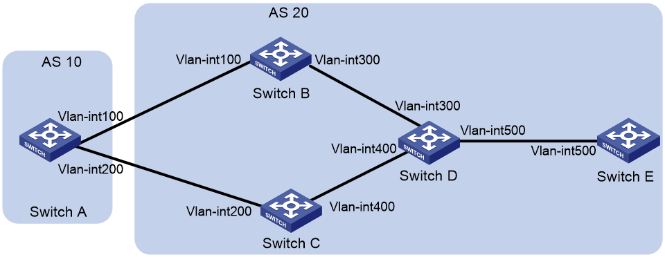
Table 2 Interface and IP address assignment
|
Device |
Interface |
IP address |
Device |
Interface |
IP address |
|
Switch A |
Vlan-int100 |
10.1.1.1/24 |
Switch D |
Vlan-int300 |
30.1.1.1/24 |
|
|
Vlan-int200 |
20.1.1.1/24 |
|
Vlan-int400 |
40.1.1.1/24 |
|
Switch B |
Vlan-int100 |
10.1.1.2/24 |
|
Vlan-int500 |
50.1.1.1/24 |
|
|
Vlan-int300 |
30.1.1.2/24 |
Switch E |
Vlan-int500 |
50.1.1.2/24 |
|
Switch C |
Vlan-int200 |
20.1.1.2/24 |
|
|
|
|
|
Vlan-int400 |
40.1.1.2/24 |
|
|
|
Configuration procedure
1. Configure IP addresses for interfaces. (Details not shown.)
2. Configure BGP connections:
# Configure Switch A.
<SwitchA> system-view
[SwitchA] bgp 10
[SwitchA-bgp-default] peer 10.1.1.2 as-number 20
[SwitchA-bgp-default] peer 20.1.1.2 as-number 20
[SwitchA-bgp-default] address-family ipv4 unicast
[SwitchA-bgp-default-ipv4] peer 10.1.1.2 enable
[SwitchA-bgp-default-ipv4] peer 20.1.1.2 enable
# Configure Switch B.
<SwitchB> system-view
[SwitchB] bgp 20
[SwitchB-bgp-default] peer 10.1.1.1 as-number 10
[SwitchB-bgp-default] peer 30.1.1.1 as-number 20
[SwitchB-bgp-default] address-family ipv4 unicast
[SwitchB-bgp-default-ipv4] peer 10.1.1.1 enable
[SwitchB-bgp-default-ipv4] peer 30.1.1.1 enable
# Configure Switch C.
<SwitchC> system-view
[SwitchC] bgp 20
[SwitchC-bgp-default] peer 20.1.1.1 as-number 10
[SwitchC-bgp-default] peer 40.1.1.1 as-number 20
[SwitchC-bgp-default] address-family ipv4 unicast
[SwitchC-bgp-default-ipv4] peer 10.1.1.1 enable
[SwitchC-bgp-default-ipv4] peer 30.1.1.1 enable
# Configure Switch D.
<SwitchD> system-view
[SwitchD] bgp 20
[SwitchD-bgp-default] peer 30.1.1.2 as-number 20
[SwitchD-bgp-default] peer 40.1.1.2 as-number 20
[SwitchD-bgp-default] peer 50.1.1.2 as-number 20
[SwitchD-bgp-default] address-family ipv4 unicast
[SwitchD-bgp-default-ipv4] peer 30.1.1.2 enable
[SwitchD-bgp-default-ipv4] peer 40.1.1.2 enable
[SwitchD-bgp-default-ipv4] peer 50.1.1.2 enable
# Configure Switch E.
<SwitchE> system-view
[SwitchE] bgp 20
[SwitchE-bgp-default] peer 50.1.1.1 as-number 20
[SwitchE-bgp-default] address-family ipv4 unicast
[SwitchE-bgp-default-ipv4] peer 50.1.1.1 enable
3. Configure Switch A to advertise network 10.1.1.0/24.
[SwitchA-bgp-default-ipv4] network 10.1.1.0 24
4. Set the local switch as the next hop for routes sent to a peer:
# Configure Switch B.
[SwitchB-bgp-default-ipv4] peer 30.1.1.1 next-hop-local
# Configure Switch C.
[SwitchC-bgp-default-ipv4] peer 40.1.1.1 next-hop-local
5. Configure Switch D as a route reflector.
[SwitchD-bgp-default-ipv4] peer 50.1.1.2 reflect-client
6. Configure the additional path feature:
# Enable the additional path sending capability on Switch D.
[SwitchD-bgp-default-ipv4] peer 50.1.1.2 additional-paths send
# Set the maximum number to 2 for Add-Path optimal routes that can be advertised.
[SwitchD-bgp-default-ipv4] additional-paths select-best 2
# Set the maximum number to 2 for Add-Path optimal routes that can be advertised to peer 50.1.1.2.
[SwitchD-bgp-default-ipv4] peer 50.1.1.2 advertise additional-paths best 2
# Enable the additional path receiving capability on Switch E.
[SwitchE-bgp-default-ipv4] peer 50.1.1.1 additional-paths receive
Verifying the configuration
# Display BGP routing information on Switch E.
[Switch E] display bgp routing-table ipv4
Total number of routes: 2
BGP local Switch ID is 50.1.1.2
Status codes: * - valid, > - best, d - dampened, h - history
s - suppressed, S - stale, i - internal, e - external
a - additional-path
Origin: i - IGP, e - EGP, ? - incomplete
Network NextHop MED LocPrf PrefVal Path/Ogn
i 10.1.1.0/24 30.1.1.2 0 100 0 10i
i 40.1.1.2 0 100 0 10i
The output shows that Switch D has learned two routes with the same prefix and different next hops.
BGP community configuration example
Network requirements
As shown in Figure 23, Switch B establishes EBGP connections with Switch A and Switch C. Configure NO_EXPORT community attribute on Switch A to make routes from AS 10 not advertised by AS 20 to any other AS.
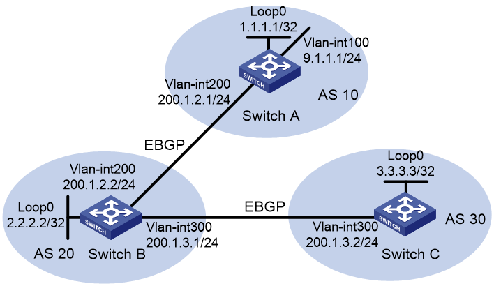
Configuration procedure
1. Configure IP addresses for interfaces. (Details not shown.)
2. Configure EBGP connections:
# Configure Switch A.
<SwitchA> system-view
[SwitchA] bgp 10
[SwitchA-bgp-default] router-id 1.1.1.1
[SwitchA-bgp-default] peer 200.1.2.2 as-number 20
[SwitchA-bgp-default] address-family ipv4 unicast
[SwitchA-bgp-default-ipv4] peer 200.1.2.2 enable
[SwitchA-bgp-default-ipv4] network 9.1.1.0 255.255.255.0
[SwitchA-bgp-default] quit
# Configure Switch B.
<SwitchB> system-view
[SwitchB] bgp 20
[SwitchB-bgp-default] router-id 2.2.2.2
[SwitchB-bgp-default] peer 200.1.2.1 as-number 10
[SwitchB-bgp-default] peer 200.1.3.2 as-number 30
[SwitchB-bgp-default] address-family ipv4 unicast
[SwitchB-bgp-default-ipv4] peer 200.1.2.1 enable
[SwitchB-bgp-default-ipv4] peer 200.1.3.2 enable
[SwitchB-bgp-default-ipv4] quit
[SwitchB-bgp-default] quit
# Configure Switch C.
<SwitchC> system-view
[SwitchC] bgp 30
[SwitchC-bgp-default] router-id 3.3.3.3
[SwitchC-bgp-default] peer 200.1.3.1 as-number 20
[SwitchC-bgp-default] address-family ipv4 unicast
[SwitchC-bgp-default-ipv4] peer 200.1.3.1 enable
[SwitchC-bgp-default-ipv4] quit
[SwitchC-bgp-default] quit
# Display the BGP routing table on Switch B.
[SwitchB] display bgp routing-table ipv4 9.1.1.0
BGP local router ID: 2.2.2.2
Local AS number: 20
Paths: 1 available, 1 best
BGP routing table information of 9.1.1.0/24:
From : 200.1.2.1 (1.1.1.1)
Rely nexthop : 200.1.2.1
Original nexthop: 200.1.2.1
OutLabel : NULL
RxPathID : 0x0
TxPathID : 0x0
AS-path : 10
Origin : igp
Attribute value : pref-val 0
State : valid, external, best
IP precedence : N/A
QoS local ID : N/A
Traffic index : N/A
# Display advertisement information of network 9.1.1.0 on Switch B.
[SwitchB] display bgp routing-table ipv4 9.1.1.0 advertise-info
BGP local router ID: 2.2.2.2
Local AS number: 20
Paths: 1 best
BGP routing table information of 9.1.1.0/24:
Advertised to peers (1 in total):
200.1.3.2
The output shows that Switch B can advertise the route with the destination 9.1.1.0/24 to other ASs through BGP.
# Display the BGP routing table on Switch C.
[SwitchC] display bgp routing-table ipv4
Total number of routes: 1
BGP local router ID is 3.3.3.3
Status codes: * - valid, > - best, d - dampened, h - history,
s - suppressed, S - stale, i - internal, e - external
a – additional-path
Origin: i - IGP, e - EGP, ? - incomplete
Network NextHop MED LocPrf PrefVal Path/Ogn
* >e 9.1.1.0/24 200.1.3.1 0 20 10i
The output shows that Switch C has learned route 9.1.1.0/24 from Switch B.
3. Configure a BGP community:
# Configure a routing policy.
[SwitchA] route-policy comm_policy permit node 0
[SwitchA-route-policy-comm_policy-0] apply community no-export
[SwitchA-route-policy-comm_policy-0] quit
# Apply the routing policy.
[SwitchA] bgp 10
[SwitchA-bgp-default] address-family ipv4 unicast
[SwitchA-bgp-default-ipv4] peer 200.1.2.2 route-policy comm_policy export
[SwitchA-bgp-default-ipv4] peer 200.1.2.2 advertise-community
Verifying the configuration
# Display the routing table on Switch B.
[SwitchB] display bgp routing-table ipv4 9.1.1.0
BGP local router ID: 2.2.2.2
Local AS number: 20
Paths: 1 available, 1 best
BGP routing table information of 9.1.1.0/24:
From : 200.1.2.1 (1.1.1.1)
Rely nexthop : 200.1.2.1
Original nexthop: 200.1.2.1
OutLabel : NULL
RxPathID : 0x0
TxPathID : 0x0
Community : No-Export
AS-path : 10
Origin : igp
Attribute value : pref-val 0
State : valid, external, best
IP precedence : N/A
QoS local ID : N/A
Traffic index : N/A
# Display advertisement information for the route 9.1.1.0 on Switch B.
[SwitchB] display bgp routing-table ipv4 9.1.1.0 advertise-info
BGP local router ID: 2.2.2.2
Local AS number: 20
Paths: 1 best
BGP routing table information of 9.1.1.0/24:
Not advertised to any peers yet
# Display the BGP routing table on Switch C.
[SwitchC] display bgp routing-table ipv4
Total number of routes: 0
The output shows that BGP has not learned any route.
BGP route reflector configuration example
Network requirements
As shown in Figure 24, all switches run BGP. Run EBGP between Switch A and Switch B, and run IBGP between Switch C and Switch B, and between Switch C and Switch D.
Configure Switch C as a route reflector with clients Switch B and Switch D to allow Switch D to learn route 20.0.0.0/8 from Switch C.
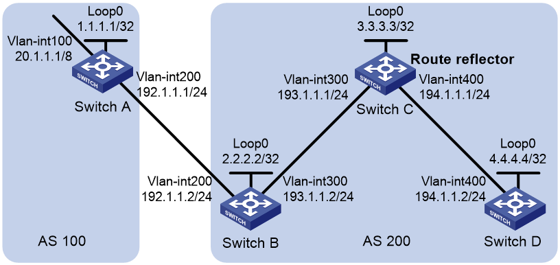
Configuration procedure
1. Configure IP addresses for interfaces and configure OSPF in AS 200. (Details not shown.)
2. Configure BGP connections:
# Configure Switch A.
<SwitchA> system-view
[SwitchA] bgp 100
[SwitchA-bgp-default] router-id 1.1.1.1
[SwitchA-bgp-default] peer 192.1.1.2 as-number 200
[SwitchA-bgp-default] address-family ipv4 unicast
[SwitchA-bgp-default-ipv4] peer 192.1.1.2 enable
# Inject network 20.0.0.0/8 to the BGP routing table.
[SwitchA-bgp-default-ipv4] network 20.0.0.0
[SwitchA-bgp-default-ipv4] quit
[SwitchA-bgp-default] quit
# Configure Switch B.
<SwitchB> system-view
[SwitchB] bgp 200
[SwitchB-bgp-default] router-id 2.2.2.2
[SwitchB-bgp-default] peer 192.1.1.1 as-number 100
[SwitchB-bgp-default] peer 193.1.1.1 as-number 200
[SwitchB-bgp-default] address-family ipv4 unicast
[SwitchB-bgp-default-ipv4] peer 192.1.1.1 enable
[SwitchB-bgp-default-ipv4] peer 193.1.1.1 enable
[SwitchB-bgp-default-ipv4] peer 193.1.1.1 next-hop-local
[SwitchB-bgp-default-ipv4] quit
[SwitchB-bgp-default] quit
# Configure Switch C.
<SwitchC> system-view
[SwitchC] bgp 200
[SwitchC-bgp-default] router-id 3.3.3.3
[SwitchC-bgp-default] peer 193.1.1.2 as-number 200
[SwitchC-bgp-default] peer 194.1.1.2 as-number 200
[SwitchC-bgp-default] address-family ipv4 unicast
[SwitchC-bgp-default-ipv4] peer 193.1.1.2 enable
[SwitchC-bgp-default-ipv4] peer 194.1.1.2 enable
[SwitchC-bgp-default-ipv4] quit
[SwitchC-bgp-default] quit
# Configure Switch D.
<SwitchD> system-view
[SwitchD] bgp 200
[SwitchD-bgp-default] router-id 4.4.4.4
[SwitchD-bgp-default] peer 194.1.1.1 as-number 200
[SwitchD-bgp-default] address-family ipv4 unicast
[SwitchD-bgp-default-ipv4] peer 194.1.1.1 enable
[SwitchD-bgp-default-ipv4] quit
[SwitchD-bgp-default] quit
3. Configure Switch C as the route reflector.
[SwitchC] bgp 200
[SwitchC-bgp-default] address-family ipv4 unicast
[SwitchC-bgp-default-ipv4] peer 193.1.1.2 reflect-client
[SwitchC-bgp-default-ipv4] peer 194.1.1.2 reflect-client
[SwitchC-bgp-default-ipv4] quit
[SwitchC-bgp-default] quit
Verifying the configuration
# Display the BGP routing table on Switch B.
[SwitchB] display bgp routing-table ipv4
Total number of routes: 1
BGP local router ID is 2.2.2.2
Status codes: * - valid, > - best, d - dampened, h - history,
s - suppressed, S - stale, i - internal, e - external
a – additional-path
Origin: i - IGP, e - EGP, ? - incomplete
Network NextHop MED LocPrf PrefVal Path/Ogn
* >e 20.0.0.0 192.1.1.1 0 0 100i
# Display the BGP routing table on Switch D.
[SwitchD] display bgp routing-table ipv4
Total number of routes: 1
BGP local router ID is 4.4.4.4
Status codes: * - valid, > - best, d - dampened, h - history,
s - suppressed, S - stale, i - internal, e - external
a – additional-path
Origin: i - IGP, e - EGP, ? - incomplete
Network NextHop MED LocPrf PrefVal Path/Ogn
* >i 20.0.0.0 193.1.1.2 0 100 0 100i
The output shows that Switch D has learned route 20.0.0.0/8 from Switch C.
BGP confederation configuration example
Network requirements
As shown in Figure 25, split AS 200 into three sub-ASs (AS 65001, AS 65002, and AS 65003) to reduce IBGP connections. Switches in AS 65001 are fully meshed.
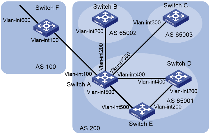
Table 3 Interface and IP address assignment
|
Device |
Interface |
IP address |
Device |
Interface |
IP address |
|
Switch A |
Vlan-int100 |
200.1.1.1/24 |
Switch D |
Vlan-int200 |
10.1.5.1/24 |
|
|
Vlan-int200 |
10.1.1.1/24 |
|
Vlan-int400 |
10.1.3.2/24 |
|
|
Vlan-int300 |
10.1.2.1/24 |
Switch E |
Vlan-int200 |
10.1.5.2/24 |
|
|
Vlan-int400 |
10.1.3.1/24 |
|
Vlan-int500 |
10.1.4.2/24 |
|
|
Vlan-int500 |
10.1.4.1/24 |
Switch F |
Vlan-int100 |
200.1.1.2/24 |
|
Switch B |
Vlan-int200 |
10.1.1.2/24 |
|
Vlan-int600 |
9.1.1.1/24 |
|
Switch C |
Vlan-int300 |
10.1.2.2/24 |
|
|
|
Configuration procedure
1. Configure IP addresses for interfaces. (Details not shown.)
2. Configure BGP confederation:
# Configure Switch A.
<SwitchA> system-view
[SwitchA] bgp 65001
[SwitchA-bgp-default] router-id 1.1.1.1
[SwitchA-bgp-default] confederation id 200
[SwitchA-bgp-default] confederation peer-as 65002 65003
[SwitchA-bgp-default] peer 10.1.1.2 as-number 65002
[SwitchA-bgp-default] peer 10.1.2.2 as-number 65003
[SwitchA-bgp-default] address-family ipv4 unicast
[SwitchA-bgp-default-ipv4] peer 10.1.1.2 enable
[SwitchA-bgp-default-ipv4] peer 10.1.2.2 enable
[SwitchA-bgp-default-ipv4] peer 10.1.1.2 next-hop-local
[SwitchA-bgp-default-ipv4] peer 10.1.2.2 next-hop-local
[SwitchA-bgp-default-ipv4] quit
[SwitchA-bgp-default] quit
# Configure Switch B.
<SwitchB> system-view
[SwitchB] bgp 65002
[SwitchB-bgp-default] router-id 2.2.2.2
[SwitchB-bgp-default] confederation id 200
[SwitchB-bgp-default] confederation peer-as 65001 65003
[SwitchB-bgp-default] peer 10.1.1.1 as-number 65001
[SwitchB-bgp-default] address-family ipv4 unicast
[SwitchB-bgp-default-ipv4] peer 10.1.1.1 enable
[SwitchB-bgp-default-ipv4] quit
[SwitchB-bgp-default] quit
# Configure Switch C.
<SwitchC> system-view
[SwitchC] bgp 65003
[SwitchC-bgp-default] router-id 3.3.3.3
[SwitchC-bgp-default] confederation id 200
[SwitchC-bgp-default] confederation peer-as 65001 65002
[SwitchC-bgp-default] peer 10.1.2.1 as-number 65001
[SwitchC-bgp-default] address-family ipv4 unicast
[SwitchC-bgp-default-ipv4] peer 10.1.2.1 enable
[SwitchC-bgp-default-ipv4] quit
[SwitchC-bgp-default] quit
3. Configure IBGP connections in AS 65001:
# Configure Switch A.
[SwitchA] bgp 65001
[SwitchA-bgp-default] peer 10.1.3.2 as-number 65001
[SwitchA-bgp-default] peer 10.1.4.2 as-number 65001
[SwitchA-bgp-default] address-family ipv4 unicast
[SwitchA-bgp-default-ipv4] peer 10.1.3.2 enable
[SwitchA-bgp-default-ipv4] peer 10.1.4.2 enable
[SwitchA-bgp-default-ipv4] peer 10.1.3.2 next-hop-local
[SwitchA-bgp-default-ipv4] peer 10.1.4.2 next-hop-local
[SwitchA-bgp-default-ipv4] quit
[SwitchA-bgp-default] quit
# Configure Switch D.
<SwitchD> system-view
[SwitchD] bgp 65001
[SwitchD-bgp-default] router-id 4.4.4.4
[SwitchD-bgp-default] confederation id 200
[SwitchD-bgp-default] peer 10.1.3.1 as-number 65001
[SwitchD-bgp-default] peer 10.1.5.2 as-number 65001
[SwitchD-bgp-default] address-family ipv4 unicast
[SwitchD-bgp-default-ipv4] peer 10.1.3.1 enable
[SwitchD-bgp-default-ipv4] peer 10.1.5.2 enable
[SwitchD-bgp-default-ipv4] quit
[SwitchD-bgp-default] quit
# Configure Switch E.
<SwitchE> system-view
[SwitchE] bgp 65001
[SwitchE-bgp-default] router-id 5.5.5.5
[SwitchE-bgp-default] confederation id 200
[SwitchE-bgp-default] peer 10.1.4.1 as-number 65001
[SwitchE-bgp-default] peer 10.1.5.1 as-number 65001
[SwitchE-bgp-default] address-family ipv4 unicast
[SwitchE-bgp-default-ipv4] peer 10.1.4.1 enable
[SwitchE-bgp-default-ipv4] peer 10.1.5.1 enable
[SwitchE-bgp-default-ipv4] quit
[SwitchE-bgp-default] quit
4. Configure the EBGP connection between AS 100 and AS 200:
# Configure Switch A.
[SwitchA] bgp 65001
[SwitchA-bgp-default] peer 200.1.1.2 as-number 100
[SwitchA-bgp-default] address-family ipv4 unicast
[SwitchA-bgp-default-ipv4] peer 200.1.1.2 enable
[SwitchA-bgp-default-ipv4] quit
[SwitchA-bgp-default] quit
# Configure Switch F.
<SwitchF> system-view
[SwitchF] bgp 100
[SwitchF-bgp-default] router-id 6.6.6.6
[SwitchF-bgp-default] peer 200.1.1.1 as-number 200
[SwitchF-bgp-default] address-family ipv4 unicast
[SwitchF-bgp-default-ipv4] peer 200.1.1.1 enable
[SwitchF-bgp-default-ipv4] network 9.1.1.0 255.255.255.0
[SwitchF-bgp-default-ipv4] quit
[SwitchF-bgp-default] quit
Verifying the configuration
# Display the routing table on Switch B.
[SwitchB] display bgp routing-table ipv4
Total number of routes: 1
BGP local router ID is 2.2.2.2
Status codes: * - valid, > - best, d - dampened, h - history,
s - suppressed, S - stale, i - internal, e - external
a – additional-path
Origin: i - IGP, e - EGP, ? - incomplete
Network NextHop MED LocPrf PrefVal Path/Ogn
* >i 9.1.1.0/24 10.1.1.1 0 100 0 (65001)
100i
[SwitchB] display bgp routing-table ipv4 9.1.1.0
BGP local router ID: 2.2.2.2
Local AS number: 65002
Paths: 1 available, 1 best
BGP routing table information of 9.1.1.0/24:
From : 10.1.1.1 (1.1.1.1)
Rely nexthop : 10.1.1.1
Original nexthop: 10.1.1.1
OutLabel : NULL
RxPathID : 0x0
TxPathID : 0x0
AS-path : (65001) 100
Origin : igp
Attribute value : MED 0, localpref 100, pref-val 0, pre 255
State : valid, external-confed, best
IP precedence : N/A
QoS local ID : N/A
Traffic index : N/A
# Display the BGP routing table on Switch D.
[SwitchD] display bgp routing-table ipv4
Total number of routes: 1
BGP local router ID is 4.4.4.4
Status codes: * - valid, > - best, d - dampened, h - history,
s - suppressed, S - stale, i - internal, e - external
a – additional-path
Origin: i - IGP, e - EGP, ? - incomplete
Network NextHop MED LocPrf PrefVal Path/Ogn
* >i 9.1.1.0/24 10.1.3.1 0 100 0 100i
[SwitchD] display bgp routing-table ipv4 9.1.1.0
BGP local router ID: 4.4.4.4
Local AS number: 65001
Paths: 1 available, 1 best
BGP routing table information of 9.1.1.0/24:
From : 10.1.3.1 (1.1.1.1)
Rely nexthop : 10.1.3.1
Original nexthop: 10.1.3.1
OutLabel : NULL
RxPathID : 0x0
TxPathID : 0x0
AS-path : 100
Origin : igp
Attribute value : MED 0, localpref 100, pref-val 0, pre 255
State : valid, internal-confed, best
IP precedence : N/A
QoS local ID : N/A
Traffic index : N/A
The output shows the following:
· Switch F can send route information to Switch B and Switch C through the confederation by establishing only an EBGP connection with Switch A.
· Switch B and Switch D are in the same confederation, but belong to different sub-ASs. They obtain external route information from Switch A, and generate identical BGP route entries although they have no direct connection in between.
BGP path selection configuration example
Network requirements
As shown in Figure 26, all switches run BGP.
· EBGP runs between Switch A and Switch B, and between Switch A and Switch C.
· IBGP runs between Switch B and Switch D, and between Switch D and Switch C. OSPF is the IGP protocol in AS 200.
Configure routing policies, making Switch D use the route 1.0.0.0/8 from Switch C as the optimal.
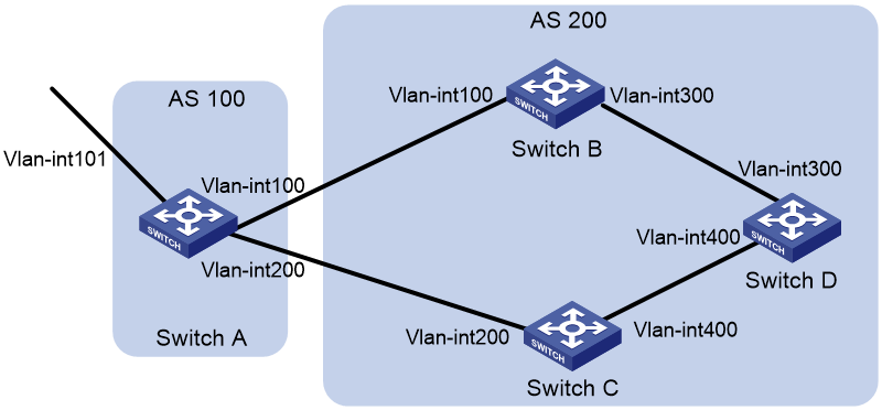
Table 4 Interface and IP address assignment
|
Device |
Interface |
IP address |
Device |
Interface |
IP address |
|
Switch A |
Vlan-int101 |
1.0.0.1/8 |
Switch D |
Vlan-int400 |
195.1.1.1/24 |
|
|
Vlan-int100 |
192.1.1.1/24 |
|
Vlan-int300 |
194.1.1.1/24 |
|
|
Vlan-int200 |
193.1.1.1/24 |
Switch C |
Vlan-int400 |
195.1.1.2/24 |
|
Switch B |
Vlan-int100 |
192.1.1.2/24 |
|
Vlan-int200 |
193.1.1.2/24 |
|
|
Vlan-int300 |
194.1.1.2/24 |
|
|
|
Configuration procedure
1. Configure IP addresses for interfaces. (Details not shown.)
2. Configure OSPF on Switch B, Switch C, and Switch D:
# Configure Switch B.
<SwitchB> system-view
[SwitchB] ospf
[SwitchB-ospf] area 0
[SwitchB-ospf-1-area-0.0.0.0] network 192.1.1.0 0.0.0.255
[SwitchB-ospf-1-area-0.0.0.0] network 194.1.1.0 0.0.0.255
[SwitchB-ospf-1-area-0.0.0.0] quit
[SwitchB-ospf-1] quit
# Configure Switch C.
<SwitchC> system-view
[SwitchC] ospf
[SwitchC-ospf] area 0
[SwitchC-ospf-1-area-0.0.0.0] network 193.1.1.0 0.0.0.255
[SwitchC-ospf-1-area-0.0.0.0] network 195.1.1.0 0.0.0.255
[SwitchC-ospf-1-area-0.0.0.0] quit
[SwitchC-ospf-1] quit
# Configure Switch D.
<SwitchD> system-view
[SwitchD] ospf
[SwitchD-ospf] area 0
[SwitchD-ospf-1-area-0.0.0.0] network 194.1.1.0 0.0.0.255
[SwitchD-ospf-1-area-0.0.0.0] network 195.1.1.0 0.0.0.255
[SwitchD-ospf-1-area-0.0.0.0] quit
[SwitchD-ospf-1] quit
3. Configure BGP connections:
# Configure Switch A.
<SwitchA> system-view
[SwitchA] bgp 100
[SwitchA-bgp-default] peer 192.1.1.2 as-number 200
[SwitchA-bgp-default] peer 193.1.1.2 as-number 200
[SwitchA-bgp-default] address-family ipv4 unicast
[SwitchA-bgp-default-ipv4] peer 192.1.1.2 enable
[SwitchA-bgp-default-ipv4] peer 193.1.1.2 enable
# Inject network 1.0.0.0/8 to the BGP routing table on Switch A.
[SwitchA-bgp-default-ipv4] network 1.0.0.0 8
[SwitchA-bgp-default-ipv4] quit
[SwitchA-bgp-default] quit
# Configure Switch B.
[SwitchB] bgp 200
[SwitchB-bgp-default] peer 192.1.1.1 as-number 100
[SwitchB-bgp-default] peer 194.1.1.1 as-number 200
[SwitchB-bgp-default] address-family ipv4 unicast
[SwitchB-bgp-default-ipv4] peer 192.1.1.1 enable
[SwitchB-bgp-default-ipv4] peer 194.1.1.1 enable
[SwitchB-bgp-default-ipv4] quit
[SwitchB-bgp-default] quit
# Configure Switch C.
[SwitchC] bgp 200
[SwitchC-bgp-default] peer 193.1.1.1 as-number 100
[SwitchC-bgp-default] peer 195.1.1.1 as-number 200
[SwitchC-bgp-default] address-family ipv4 unicast
[SwitchC-bgp-default-ipv4] peer 193.1.1.1 enable
[SwitchC-bgp-default-ipv4] peer 195.1.1.1 enable
[SwitchC-bgp-default-ipv4] quit
[SwitchC-bgp-default] quit
# Configure Switch D.
[SwitchD] bgp 200
[SwitchD-bgp-default] peer 194.1.1.2 as-number 200
[SwitchD-bgp-default] peer 195.1.1.2 as-number 200
[SwitchD-bgp-default] address-family ipv4 unicast
[SwitchD-bgp-default-ipv4] peer 194.1.1.2 enable
[SwitchD-bgp-default-ipv4] peer 195.1.1.2 enable
[SwitchD-bgp-default-ipv4] quit
[SwitchD-bgp-default] quit
4. Configure local preference for route 1.0.0.0/8, making Switch D give priority to the route learned from Switch C:
# Define IPv4 basic ACL 2000 on Switch C to permit route 1.0.0.0/8.
[SwitchC] acl basic 2000
[SwitchC-acl-ipv4-basic-2000] rule permit source 1.0.0.0 0.255.255.255
[SwitchC-acl-ipv4-basic-2000] quit
# Configure a routing policy named localpref on Switch C, setting the local preference of route 1.0.0.0/8 to 200 (the default is 100).
[SwitchC] route-policy localpref permit node 10
[SwitchC-route-policy-localpref-10] if-match ip address acl 2000
[SwitchC-route-policy-localpref-10] apply local-preference 200
[SwitchC-route-policy-localpref-10] quit
# Apply routing policy localpref to routes from peer 193.1.1.1.
[SwitchC] bgp 200
[SwitchC-bgp-default] address-family ipv4 unicast
[SwitchC-bgp-default-ipv4] peer 193.1.1.1 route-policy localpref import
[SwitchC-bgp-default-ipv4] quit
[SwitchC-bgp-default] quit
# Display the BGP routing table on Switch D.
[SwitchD] display bgp routing-table ipv4
Total number of routes: 2
BGP local router ID is 195.1.1.1
Status codes: * - valid, > - best, d - dampened, h - history,
s - suppressed, S - stale, i - internal, e - external
a – additional-path
Origin: i - IGP, e - EGP, ? - incomplete
Network NextHop MED LocPrf PrefVal Path/Ogn
* >i 1.0.0.0 193.1.1.1 200 0 100i
* i 192.1.1.1 100 0 100i
Route 1.0.0.0/8 learned from Switch C is the optimal.
BGP GR configuration example
Network requirements
As shown in Figure 27, all switches run BGP. EBGP runs between Switch A and Switch B. IBGP runs between Switch B and Switch C.
Enable GR capability for BGP so that the communication between Switch A and Switch C is not affected when an active/standby switchover occurs on Switch B.
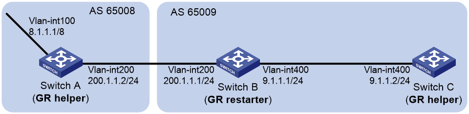
Configuration procedure
1. Configure Switch A:
# Configure IP addresses for interfaces. (Details not shown.)
# Configure the EBGP connection.
<SwitchA> system-view
[SwitchA] bgp 65008
[SwitchA-bgp-default] router-id 1.1.1.1
[SwitchA-bgp-default] peer 200.1.1.1 as-number 65009
# Enable GR capability for BGP.
[SwitchA-bgp-default] graceful-restart
# Inject network 8.0.0.0/8 to the BGP routing table.
[SwitchA-bgp-default] address-family ipv4
[SwitchA-bgp-default-ipv4] network 8.0.0.0
# Enable Switch A to exchange IPv4 unicast routing information with Switch B.
[SwitchA-bgp-default-ipv4] peer 200.1.1.1 enable
2. Configure Switch B:
# Configure IP addresses for interfaces. (Details not shown.)
# Configure the EBGP connection.
<SwitchB> system-view
[SwitchB] bgp 65009
[SwitchB-bgp-default] router-id 2.2.2.2
[SwitchB-bgp-default] peer 200.1.1.2 as-number 65008
# Configure the IBGP connection.
[SwitchB-bgp-default] peer 9.1.1.2 as-number 65009
# Enable GR capability for BGP.
[SwitchB-bgp-default] graceful-restart
# Inject networks 200.1.1.0/24 and 9.1.1.0/24 to the BGP routing table.
[SwitchB-bgp-default] address-family ipv4
[SwitchB-bgp-default-ipv4] network 200.1.1.0 24
[SwitchB-bgp-default-ipv4] network 9.1.1.0 24
# Enable Switch B to exchange IPv4 unicast routing information with Switch A and Switch C.
[SwitchB-bgp-default-ipv4] peer 200.1.1.2 enable
[SwitchB-bgp-default-ipv4] peer 9.1.1.2 enable
3. Configure Switch C:
# Configure IP addresses for interfaces. (Details not shown.)
# Configure the IBGP connection.
<SwitchC> system-view
[SwitchC] bgp 65009
[SwitchC-bgp-default] router-id 3.3.3.3
[SwitchC-bgp-default] peer 9.1.1.1 as-number 65009
# Enable GR capability for BGP.
[SwitchC-bgp-default] graceful-restart
# Enable Switch C to exchange IPv4 unicast routing information with Switch B.
[SwitchC-bgp-default-ipv4] peer 9.1.1.1 enable
Verifying the configuration
Ping Switch C on Switch A. Meanwhile, perform an active/standby switchover on Switch B. The ping operation is successful during the whole switchover process. (Details not shown.)
BFD for BGP configuration example
Network requirements
As shown in Figure 28, configure OSPF as the IGP in AS 200.
· Establish two IBGP connections between Switch A and Switch C. When both paths operate correctly, Switch C uses the path Switch A<—>Switch B<—>Switch C to exchange packets with network 1.1.1.0/24.
· Configure BFD over the path. When the path fails, BFD can quickly detect the failure and notify it to BGP. Then, the path Switch A<—>Switch D<—>Switch C takes effect immediately.

Table 5 Interface and IP address assignment
|
Device |
Interface |
IP address |
Device |
Interface |
IP address |
|
Switch A |
Vlan-int100 |
3.0.1.1/24 |
Switch C |
Vlan-int101 |
3.0.2.2/24 |
|
|
Vlan-int200 |
2.0.1.1/24 |
|
Vlan-int201 |
2.0.2.2/24 |
|
Switch B |
Vlan-int100 |
3.0.1.2/24 |
Switch D |
Vlan-int200 |
2.0.1.2/24 |
|
|
Vlan-int101 |
3.0.2.1/24 |
|
Vlan-int201 |
2.0.2.1/24 |
Configuration procedure
1. Configure IP addresses for interfaces. (Details not shown.)
2. Configure OSPF to ensure that Switch A and Switch C are reachable to each other. (Details not shown.)
3. Configure BGP on Switch A:
# Establish two IBGP connections to Switch C.
<SwitchA> system-view
[SwitchA] bgp 200
[SwitchA-bgp-default] peer 3.0.2.2 as-number 200
[SwitchA-bgp-default] peer 2.0.2.2 as-number 200
[SwitchA-bgp-default] address-family ipv4 unicast
[SwitchA-bgp-default-ipv4] peer 3.0.2.2 enable
[SwitchA-bgp-default-ipv4] peer 2.0.2.2 enable
[SwitchA-bgp-default-ipv4] quit
[SwitchA-bgp-default] quit
# Create IPv4 basic ACL 2000 to permit 1.1.1.0/24 to pass.
[SwitchA] acl basic 2000
[SwitchA-acl-ipv4-basic-2000] rule permit source 1.1.1.0 0.0.0.255
[SwitchA-acl-ipv4-basic-2000] quit
# Create two routing policies to set the MED for route 1.1.1.0/24. The policy apply_med_50 sets the MED to 50, and the policy apply_med_100 sets the MED to 100.
[SwitchA] route-policy apply_med_50 permit node 10
[SwitchA-route-policy-apply_med_50-10] if-match ip address acl 2000
[SwitchA-route-policy-apply_med_50-10] apply cost 50
[SwitchA-route-policy-apply_med_50-10] quit
[SwitchA] route-policy apply_med_100 permit node 10
[SwitchA-route-policy-apply_med_100-10] if-match ip address acl 2000
[SwitchA-route-policy-apply_med_100-10] apply cost 100
[SwitchA-route-policy-apply_med_100-10] quit
# Apply routing policy apply_med_50 to routes outgoing to peer 3.0.2.2, and apply routing policy apply_med_100 to routes outgoing to peer 2.0.2.2.
[SwitchA] bgp 200
[SwitchA-bgp-default] address-family ipv4 unicast
[SwitchA-bgp-default-ipv4] peer 3.0.2.2 route-policy apply_med_50 export
[SwitchA-bgp-default-ipv4] peer 2.0.2.2 route-policy apply_med_100 export
[SwitchA-bgp-default-ipv4] quit
# Enable BFD for peer 3.0.2.2.
[SwitchA-bgp-default] peer 3.0.2.2 bfd
[SwitchA-bgp-default] quit
4. Configure BGP on Switch C:
# Establish two IBGP connections to Switch A.
<SwitchC> system-view
[SwitchC] bgp 200
[SwitchC-bgp-default] peer 3.0.1.1 as-number 200
[SwitchC-bgp-default] peer 2.0.1.1 as-number 200
[SwitchC-bgp-default] address-family ipv4 unicast
[SwitchC-bgp-default-ipv4] peer 3.0.1.1 enable
[SwitchC-bgp-default-ipv4] peer 2.0.1.1 enable
[SwitchC-bgp-default-ipv4] quit
# Enable BFD for peer 3.0.1.1.
[SwitchC-bgp-default] peer 3.0.1.1 bfd
[SwitchC-bgp-default] quit
[SwitchC] quit
Verifying the configuration
# Display detailed BFD session information on Switch C.
<SwitchC> display bfd session verbose
Total Session Num: 1 Up Session Num: 1 Init Mode: Active
IPv4 Session Working Under Ctrl Mode:
Local Discr: 513 Remote Discr: 513
Source IP: 3.0.2.2 Destination IP: 3.0.1.1
Session State: Up Interface: N/A
Min Tx Inter: 500ms Act Tx Inter: 500ms
Min Rx Inter: 500ms Detect Inter: 2500ms
Rx Count: 135 Tx Count: 135
Connect Type: Indirect Running Up for: 00:00:58
Hold Time: 2457ms Auth mode: None
Detect Mode: Async Slot: 0
Protocol: BGP
Version: 1
Diag Info: No Diagnostic
The output shows that a BFD session has been established between Switch A and Switch C.
# Display BGP peer information on Switch C.
<SwitchC> display bgp peer ipv4
BGP local router ID: 3.3.3.3
Local AS number: 200
Total number of peers: 2 Peers in established state: 2
* - Dynamically created peer
Peer AS MsgRcvd MsgSent OutQ PrefRcv Up/Down State
2.0.1.1 200 4 5 0 0 00:01:55 Established
3.0.1.1 200 4 5 0 0 00:01:52 Established
The output shows that Switch C has established two BGP connections with Switch A, and both connections are in Established state.
# Display route 1.1.1.0/24 on Switch C.
<SwitchC> display ip routing-table 1.1.1.0 24 verbose
Summary count : 1
Destination: 1.1.1.0/24
Protocol: BGP Process ID: 0
SubProtID: 0x1 Age: 00h00m09s
Cost: 50 Preference: 255
IpPre: N/A QosLocalID: N/A
Tag: 0 State: Active Adv
OrigTblID: 0x1 OrigVrf: default-vrf
TableID: 0x2 OrigAs: 0
NibID: 0x15000001 LastAs: 0
AttrID: 0x1 Neighbor: 3.0.1.1
Flags: 0x10060 OrigNextHop: 3.0.1.1
Label: NULL RealNextHop: 3.0.2.1
BkLabel: NULL BkNextHop: N/A
Tunnel ID: Invalid Interface: Vlan-interface101
BkTunnel ID: Invalid BkInterface: N/A
FtnIndex: 0x0 TrafficIndex: N/A
Connector: N/A
The output shows that Switch C communicates with network 1.1.1.0/24 through the path Switch C<—>Switch B<—>Switch A.
# Break down the path Switch C<—>Switch B<—>Switch A and then display route 1.1.1.0/24 on Switch C.
<SwitchC> display ip routing-table 1.1.1.0 24 verbose
Summary count : 1
Destination: 1.1.1.0/24
Protocol: BGP Process ID: 0
SubProtID: 0x1 Age: 00h03m08s
Cost: 100 Preference: 255
IpPre: N/A QosLocalID: N/A
Tag: 0 State: Active Adv
OrigTblID: 0x1 OrigVrf: default-vrf
TableID: 0x2 OrigAs: 0
NibID: 0x15000000 LastAs: 0
AttrID: 0x0 Neighbor: 2.0.1.1
Flags: 0x10060 OrigNextHop: 2.0.1.1
Label: NULL RealNextHop: 2.0.2.1
BkLabel: NULL BkNextHop: N/A
Tunnel ID: Invalid Interface: Vlan-interface201
BkTunnel ID: Invalid BkInterface: N/A
FtnIndex: 0x0 TrafficIndex: N/A
Connector: N/A
The output shows that Switch C communicates with network 1.1.1.0/24 through the path Switch C<—>Switch D<—>Switch A.
BGP FRR configuration example
Network requirements
As shown in Figure 29, configure BGP FRR so that when Link B fails, BGP uses Link A to forward traffic.
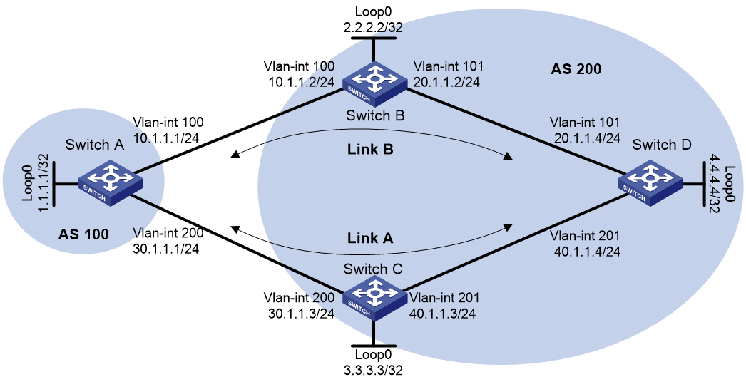
Configuration procedure
1. Configure IP addresses for interfaces. (Details not shown.)
2. Configure OSPF in AS 200 to ensure connectivity among Switch B, Switch C, and Switch D. (Details not shown.)
3. Configure BGP connections:
# Configure Switch A to establish EBGP sessions to Switch B and Switch C, and advertise network 1.1.1.1/32.
<SwitchA> system-view
[SwitchA] bgp 100
[SwitchA-bgp-default] router-id 1.1.1.1
[SwitchA-bgp-default] peer 10.1.1.2 as-number 200
[SwitchA-bgp-default] peer 30.1.1.3 as-number 200
[SwitchA-bgp-default] address-family ipv4 unicast
[SwitchA-bgp-default-ipv4] peer 10.1.1.2 enable
[SwitchA-bgp-default-ipv4] peer 30.1.1.3 enable
[SwitchA-bgp-default-ipv4] network 1.1.1.1 32
# Configure Switch B to establish an EBGP session to Switch A, and an IBGP session to Switch D.
<SwitchB> system-view
[SwitchB] bgp 200
[SwitchB-bgp-default] router-id 2.2.2.2
[SwitchB-bgp-default] peer 10.1.1.1 as-number 100
[SwitchB-bgp-default] peer 4.4.4.4 as-number 200
[SwitchB-bgp-default] peer 4.4.4.4 connect-interface loopback 0
[SwitchB-bgp-default] address-family ipv4 unicast
[SwitchB-bgp-default-ipv4] peer 10.1.1.1 enable
[SwitchB-bgp-default-ipv4] peer 4.4.4.4 enable
[SwitchB-bgp-default-ipv4] peer 4.4.4.4 next-hop-local
[SwitchB-bgp-default-ipv4] quit
[SwitchB-bgp-default] quit
# Configure Switch C to establish an EBGP session to Switch A, and an IBGP session to Switch D.
<SwitchC> system-view
[SwitchC] bgp 200
[SwitchC-bgp-default] router-id 3.3.3.3
[SwitchC-bgp-default] peer 30.1.1.1 as-number 100
[SwitchC-bgp-default] peer 4.4.4.4 as-number 200
[SwitchC-bgp-default] peer 4.4.4.4 connect-interface loopback 0
[SwitchC-bgp-default] address-family ipv4 unicast
[SwitchC-bgp-default-ipv4] peer 30.1.1.1 enable
[SwitchC-bgp-default-ipv4] peer 4.4.4.4 enable
[SwitchC-bgp-default-ipv4] peer 4.4.4.4 next-hop-local
[SwitchC-bgp-default-ipv4] quit
[SwitchC-bgp-default] quit
# Configure Switch D to establish IBGP sessions to Switch B and Switch C, and advertise network 4.4.4.4/32.
<SwitchD> system-view
[SwitchD] bgp 200
[SwitchD-bgp-default] router-id 4.4.4.4
[SwitchD-bgp-default] peer 2.2.2.2 as-number 200
[SwitchD-bgp-default] peer 2.2.2.2 connect-interface loopback 0
[SwitchD-bgp-default] peer 3.3.3.3 as-number 200
[SwitchD-bgp-default] peer 3.3.3.3 connect-interface loopback 0
[SwitchD-bgp-default] address-family ipv4 unicast
[SwitchD-bgp-default-ipv4] peer 2.2.2.2 enable
[SwitchD-bgp-default-ipv4] peer 3.3.3.3 enable
[SwitchD-bgp-default-ipv4] network 4.4.4.4 32
4. Configure preferred values so Link B is used to forward traffic between Switch A and Switch D:
# Configure Switch A to set the preferred value to 100 for routes received from Switch B.
[SwitchA-bgp-default-ipv4] peer 10.1.1.2 preferred-value 100
[SwitchA-bgp-default-ipv4] quit
[SwitchA-bgp-default] quit
# Configure Switch D to set the preferred value to 100 for routes received from Switch B.
[SwitchD-bgp-default-ipv4] peer 2.2.2.2 preferred-value 100
[SwitchD-bgp-default-ipv4] quit
[SwitchD-bgp-default] quit
5. Configure BGP FRR:
# On Switch A, set the source address of BFD echo packets to 11.1.1.1.
[SwitchA] bfd echo-source-ip 11.1.1.1
# Create routing policy frr to set a backup next hop 30.1.1.3 (Switch C) for the route destined for 4.4.4.4/32.
[SwitchA] ip prefix-list abc index 10 permit 4.4.4.4 32
[SwitchA] route-policy frr permit node 10
[SwitchA-route-policy] if-match ip address prefix-list abc
[SwitchA-route-policy] apply fast-reroute backup-nexthop 30.1.1.3
[SwitchA-route-policy] quit
# Use echo-mode BFD to detect the connectivity to Switch D.
[SwitchA] bgp 100
[SwitchA-bgp-default] primary-path-detect bfd echo
# Apply the routing policy to BGP FRR for BGP IPv4 unicast address family.
[SwitchA-bgp-default] address-family ipv4 unicast
[SwitchA-bgp-default-ipv4] fast-reroute route-policy frr
[SwitchA-bgp-default-ipv4] quit
[SwitchA-bgp-default] quit
# On Switch D, set the source address of BFD echo packets to 44.1.1.1.
[SwitchD] bfd echo-source-ip 44.1.1.1
# Create routing policy frr to set a backup next hop 3.3.3.3 (Switch C) for the route destined for 1.1.1.1/32.
[SwitchD] ip prefix-list abc index 10 permit 1.1.1.1 32
[SwitchD] route-policy frr permit node 10
[SwitchD-route-policy] if-match ip address prefix-list abc
[SwitchD-route-policy] apply fast-reroute backup-nexthop 3.3.3.3
[SwitchD-route-policy] quit
# Use echo-mode BFD to detect the connectivity to Switch A.
[SwitchD] bgp 200
[SwitchD-bgp-default] primary-path-detect bfd echo
# Apply the routing policy to BGP FRR for BGP IPv4 unicast address family.
[SwitchD-bgp-default] address-family ipv4 unicast
[SwitchD-bgp-default-ipv4] fast-reroute route-policy frr
[SwitchD-bgp-default-ipv4] quit
[SwitchD-bgp-default] quit
Verifying the configuration
# Display detailed information about the route to 4.4.4.4/32 on Switch A. The output shows the backup next hop for the route.
[SwitchA] display ip routing-table 4.4.4.4 32 verbose
Summary count : 1
Destination: 4.4.4.4/32
Protocol: BGP Process ID: 0
SubProtID: 0x2 Age: 00h01m52s
Cost: 0 Preference: 255
IpPre: N/A QosLocalID: N/A
Tag: 0 State: Active Adv
OrigTblID: 0x0 OrigVrf: default-vrf
TableID: 0x2 OrigAs: 200
NibID: 0x15000003 LastAs: 200
AttrID: 0x5 Neighbor: 10.1.1.2
Flags: 0x10060 OrigNextHop: 10.1.1.2
Label: NULL RealNextHop: 10.1.1.2
BkLabel: NULL BkNextHop: 30.1.1.3
Tunnel ID: Invalid Interface: Vlan-interface 100
BkTunnel ID: Invalid BkInterface: Vlan-interface 200
FtnIndex: 0x0 TrafficIndex: N/A
Connector: N/A
# Display detailed information about the route to 1.1.1.1/32 on Switch D. The output shows the backup next hop for the route.
[SwitchD] display ip routing-table 1.1.1.1 32 verbose
Summary count : 1
Destination: 1.1.1.1/32
Protocol: BGP Process ID: 0
SubProtID: 0x1 Age: 00h00m36s
Cost: 0 Preference: 255
IpPre: N/A QosLocalID: N/A
Tag: 0 State: Active Adv
OrigTblID: 0x0 OrigVrf: default-vrf
TableID: 0x2 OrigAs: 100
NibID: 0x15000003 LastAs: 100
AttrID: 0x1 Neighbor: 2.2.2.2
Flags: 0x10060 OrigNextHop: 2.2.2.2
Label: NULL RealNextHop: 20.1.1.2
BkLabel: NULL BkNextHop: 40.1.1.3
Tunnel ID: Invalid Interface: Vlan-interface 101
BkTunnel ID: Invalid BkInterface: Vlan-interface 201
FtnIndex: 0x0 TrafficIndex: N/A
Connector: N/A
Multicast BGP configuration example
Network requirements
As shown in Figure 30, OSPF runs within AS 100 and AS 200 to ensure intra-AS connectivity. MBGP runs between the two ASs to exchange IPv4 unicast routes used for RPF check.
· Configure the Loopback 0 interface of Switch A and Switch B as the C-BSR and C-RP.
· Configure Switch A and Switch B to establish a Multicast Source Discovery Protocol (MSDP) peer relationship through MBGP, so that the receiver can receive multicast traffic from the source.
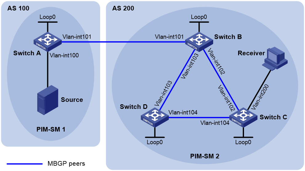
Table 6 Interface and IP address assignment
|
Device |
Interface |
IP address |
Device |
Interface |
IP address |
|
Source |
N/A |
10.110.1.100/24 |
Switch C |
Vlan-int200 |
10.110.2.1/24 |
|
Switch A |
Vlan-int100 |
10.110.1.1/24 |
|
Vlan-int102 |
192.168.2.2/24 |
|
|
Vlan-int101 |
192.168.1.1/24 |
|
Vlan-int104 |
192.168.4.1/24 |
|
|
Loop0 |
1.1.1.1/32 |
|
Loop0 |
3.3.3.3/32 |
|
Switch B |
Vlan-int101 |
192.168.1.2/24 |
Switch D |
Vlan-int103 |
192.168.3.2/24 |
|
|
Vlan-int102 |
192.168.2.1/24 |
|
Vlan-int104 |
192.168.4.2/24 |
|
|
Vlan-int103 |
192.168.3.1/24 |
|
Loop0 |
4.4.4.4/32 |
|
|
Loop0 |
2.2.2.2/32 |
|
|
|
Configuration procedure
1. Configure IP addresses for interfaces and configure OSPF (this example uses OSPF process 1) in AS 200 to ensure intra-AS connectivity. (Details not shown.)
2. Enable IP multicast routing, PIM-SM, and IGMP, and configure BSR boundaries:
# On Switch A, enable multicast routing globally, and enable PIM-SM on interfaces.
<SwitchA> system-view
[SwitchA] multicast routing
[SwitchA-mrib] quit
[SwitchA] interface vlan-interface 100
[SwitchA-Vlan-interface100] pim sm
[SwitchA-Vlan-interface100] quit
[SwitchA] interface vlan-interface 101
[SwitchA-Vlan-interface101] pim sm
[SwitchA-Vlan-interface101] quit
# Configure Switch B and Switch D in the same way that Switch A was configured.
# On Switch C, enable multicast routing globally.
<SwitchC> system-view
[SwitchC] multicast routing
[SwitchA-mrib] quit
# Enable PIM-SM on interfaces, and enable IGMP on VLAN-interface 200.
[SwitchC] interface vlan-interface 102
[SwitchC-Vlan-interface102] pim sm
[SwitchC-Vlan-interface102] quit
[SwitchC] interface vlan-interface 104
[SwitchC-Vlan-interface104] pim sm
[SwitchC-Vlan-interface104] quit
[SwitchC] interface vlan-interface 200
[SwitchC-Vlan-interface200] pim sm
[SwitchC-Vlan-interface200] igmp enable
[SwitchC-Vlan-interface200] quit
# Configure the BSR boundary on Switch A.
[SwitchA] interface vlan-interface 101
[SwitchA-Vlan-interface101] pim bsr-boundary
[SwitchA-Vlan-interface101] quit
# Configure the BSR boundary on Switch B.
[SwitchB] interface vlan-interface 101
[SwitchB-Vlan-interface101] pim bsr-boundary
[SwitchB-Vlan-interface101] quit
3. Configure Loopback 0, C-BSR, and C-RP:
# Configure the Loopback 0 interface and specify it as the C-BSR and C-RP on Switch A.
[SwitchA] interface loopback 0
[SwitchA-LoopBack0] ip address 1.1.1.1 32
[SwitchA-LoopBack0] pim sm
[SwitchA-LoopBack0] quit
[SwitchA] pim
[SwitchA-pim] c-bsr 1.1.1.1
[SwitchA-pim] c-rp 1.1.1.1
[SwitchA-pim] quit
# Configure the Loopback 0 interface and specify it as the C-BSR and C-RP on Switch B.
[SwitchB] interface loopback 0
[SwitchB-LoopBack0] ip address 2.2.2.2 32
[SwitchB-LoopBack0] pim sm
[SwitchB-LoopBack0] quit
[SwitchB] pim
[SwitchB-pim] c-bsr 2.2.2.2
[SwitchB-pim] c-rp 2.2.2.2
[SwitchB-pim] quit
4. Configure BGP to establish BGP IPv4 multicast peers and redistribute routes:
# On Switch A, establish an EBGP session to Switch B.
[SwitchA] bgp 100
[SwitchA-bgp-default] router-id 1.1.1.1
[SwitchA-bgp-default] peer 192.168.1.2 as-number 200
# Enable exchange of IPv4 unicast routes used for RPF check with Switch B.
[SwitchA-bgp-default] address-family ipv4 multicast
[SwitchA-bgp-default-mul-ipv4] peer 192.168.1.2 enable
# Redistribute direct routes into BGP.
[SwitchA-bgp-default-mul-ipv4] import-route direct
[SwitchA-bgp-default-mul-ipv4] quit
[SwitchA-bgp-default] quit
# On Switch B, establish an EBGP session to Switch A.
[SwitchB] bgp 200
[SwitchB-bgp-default] router-id 2.2.2.2
[SwitchB-bgp-default] peer 192.168.1.1 as-number 100
# Enable exchange of IPv4 unicast routes used for RPF check with Switch B.
[SwitchB-bgp-default] address-family ipv4 multicast
[SwitchB-bgp-default-mul-ipv4] peer 192.168.1.1 enable
# Redistribute OSPF routes into BGP.
[SwitchB-bgp-default-mul-ipv4] import-route ospf 1
[SwitchB-bgp-default-mul-ipv4] quit
[SwitchB-bgp-default] quit
5. Configure MSDP peers:
# Configure an MSDP peer on Switch A.
[SwitchA] msdp
[SwitchA-msdp] peer 192.168.1.2 connect-interface vlan-interface 101
[SwitchA-msdp] quit
# Configure an MSDP peer on Switch B.
[SwitchB] msdp
[SwitchB-msdp] peer 192.168.1.1 connect-interface vlan-interface 101
[SwitchB-msdp] quit
Verifying the configuration
# Verify the BGP IPv4 multicast peer information on Switch B.
[SwitchB] display bgp peer ipv4 multicast
BGP local router ID : 2.2.2.2
Local AS number : 200
Total number of peers : 3 Peers in established state : 3
Peer AS MsgRcvd MsgSent OutQ PrefRcv Up/Down State
192.168.1.1 100 56 56 0 0 00:40:54 Established
# Verify the MSDP peer information on Switch B.
[SwitchB] display msdp brief
Configured Established Listen Connect Shutdown Disabled
1 1 0 0 0 0
Peer address State Up/Down time AS SA count Reset count
192.168.1.1 Established 00:07:17 100 1 0
Dynamic BGP peer configuration example
Network requirements
As shown in Figure 31, Switch A needs to establish IBGP peer relationships with Switch B, Switch C, and Switch D in network 10.1.0.0/16. Configure dynamic BGP peers to simplify the configuration.
Configure Switch A as the route reflector, and configure Switch B, Switch C, and Switch D as its clients.
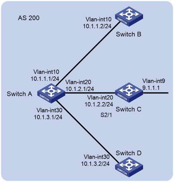
Configuration procedure
1. Configure IP addresses for interfaces. (Details not shown.)
2. Configure IBGP peer relationship:
# Configure Switch A to establish dynamic BGP peer relationships with switches in network 10.1.0.0/16.
<SwitchA> system-view
[SwitchA] bgp 200
[SwitchA-bgp-default] router-id 1.1.1.1
[SwitchA-bgp-default] peer 10.1.0.0 16 as-number 200
[SwitchA-bgp-default] address-family ipv4
[SwitchA-bgp-default-ipv4] peer 10.1.0.0 16 enable
# Configure Switch B to establish an IBGP peer relationship with Switch A.
<SwitchB> system-view
[SwitchB] bgp 200
[SwitchB-bgp-default] router-id 2.2.2.2
[SwitchB-bgp-default] peer 10.1.1.1 as-number 200
[SwitchB-bgp-default] address-family ipv4
[SwitchB-bgp-default-ipv4] peer 10.1.1.1 enable
# Configure Switch C to establish an IBGP peer relationship with Switch A.
<SwitchC> system-view
[SwitchC] bgp 200
[SwitchC-bgp-default] router-id 3.3.3.3
[SwitchC-bgp-default] peer 10.1.2.1 as-number 200
[SwitchC-bgp-default] address-family ipv4
[SwitchC-bgp-default-ipv4] peer 10.1.2.1 enable
# Configure Switch D to establish an IBGP peer relationship with Switch A.
<SwitchD> system-view
[SwitchD] bgp 200
[SwitchD-bgp-default] router-id 4.4.4.4
[SwitchD-bgp-default] peer 10.1.3.1 as-number 200
[SwitchD-bgp-default] address-family ipv4
[SwitchD-bgp-default-ipv4] peer 10.1.3.1 enable
# Display BGP peer information on Switch A. The output shows that Switch A has established IBGP peer relationships with Switch B, Switch C, and Switch D.
[SwitchA] display bgp peer ipv4
BGP local router ID : 1.1.1.1
Local AS number : 200
Total number of peers : 3 Peers in established state : 3
* - Dynamically created peer
Peer AS MsgRcvd MsgSent OutQ PrefRcv Up/Down State
*10.1.1.2 200 7 10 0 0 00:06:09 Established
*10.1.2.2 200 7 10 0 0 00:06:09 Established
*10.1.3.2 200 7 10 0 0 00:06:09 Established
3. Configure Switch A as the route reflector, and configure peers in network 10.1.0.0/16 as its clients.
[SwitchA-bgp-default-ipv4] peer 10.1.0.0 16 reflect-client
4. Configure Switch C to advertise network 9.1.1.0/24.
[SwitchC-bgp-default-ipv4] network 9.1.1.0 24
Verifying the configuration
# Verify that route 9.1.1.0/24 exists in the BGP routing table on Switch A, Switch B, and Switch D. This example uses Switch A.
[SwitchA-bgp-default] display bgp routing-table ipv4
Total Number of Routes: 1
BGP Local router ID is 1.1.1.1
Status codes: * - valid, > - best, d - dampened, h - history,
s - suppressed, S - stale, i - internal, e - external
a – additional-path
Origin: i - IGP, e - EGP, ? - incomplete
Network NextHop MED LocPrf PrefVal Path/Ogn
* i 9.1.1.0/24 10.1.2.2 0 100 0 ?
BGP LS configuration example
Network requirements
As shown in Figure 32, all switches run BGP. Run IBGP between Switch A and Switch B, between Switch B and Switch C, and between Switch B and Switch D.
Configure Switch B as a route reflector with client Switch A to allow Switch A to learn LS information advertised by Switch C and Switch D.
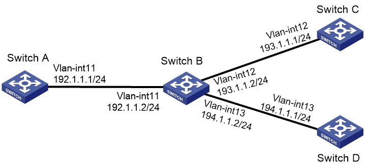
Configuration procedure
1. Configure IP addresses for interfaces and configure OSPF on Switch C and Switch D. (Details not shown.)
2. Configure BGP connections:
# Configure Switch A.
<SwitchA> system-view
[SwitchA] bgp 100
[SwitchA-bgp-default] peer 192.1.1.2 as-number 100
[SwitchA-bgp-default] address-family link-state
[SwitchA-bgp-default-ls] peer 192.1.1.2 enable
[SwitchA-bgp-default-ls] quit
[SwitchA-bgp-default] quit
# Configure Switch B.
<SwitchB> system-view
[SwitchB] bgp 100
[SwitchB-bgp-default] peer 192.1.1.1 as-number 100
[SwitchB-bgp-default] peer 193.1.1.1 as-number 100
[SwitchB-bgp-default] peer 194.1.1.1 as-number 100
[SwitchB-bgp-default] address-family link-state
[SwitchB-bgp-default-ls] peer 192.1.1.1 enable
[SwitchB-bgp-default-ls] peer 193.1.1.1 enable
[SwitchB-bgp-default-ls] peer 194.1.1.1 enable
[SwitchB-bgp-default-ls] quit
[SwitchB-bgp-default] quit
# Configure Switch C.
<SwitchC> system-view
[SwitchC] bgp 100
[SwitchC-bgp-default] peer 193.1.1.2 as-number 100
[SwitchC-bgp-default] address-family link-state
[SwitchC-bgp-default-ls] peer 193.1.1.2 enable
[SwitchC-bgp-default-ls] quit
[SwitchC-bgp-default] quit
[SwitchC] ospf
[SwitchC-ospf-1] distribute bgp-ls
[SwitchC-ospf-1] area 0
[SwitchC-ospf-1-area-0.0.0.0] network 0.0.0.0 0.0.0.0
[SwitchC-ospf-1-area-0.0.0.0] quit
[SwitchC-ospf-1] quit
# Configure Switch D.
<SwitchD> system-view
[SwitchD] bgp 100
[SwitchD-bgp-default] peer 194.1.1.2 as-number 100
[SwitchD-bgp-default] address-family link-state
[SwitchD-bgp-default-ls] peer 194.1.1.2 enable
[SwitchD-bgp-default-ls] quit
[SwitchD-bgp-default] quit
[SwitchD] ospf
[SwitchD-ospf-1] distribute bgp-ls
[SwitchD-ospf-1] area 0
[SwitchD-ospf-1-area-0.0.0.0] network 0.0.0.0 0.0.0.0
[SwitchD-ospf-1-area-0.0.0.0] quit
[SwitchD-ospf-1] quit
3. Configure Switch B as the route reflector.
[SwitchB] bgp 100
[SwitchB-bgp-default] address-family link-state
[SwitchB-bgp-default-ls] peer 192.1.1.1 reflect-client
[SwitchB-bgp-default-ls] quit
[SwitchB-bgp-default] quit
Verifying the configuration
# Verify that Switch A has learned LS information advertised by Switch C and Switch D.
[SwitchA] display bgp link-state
Total number of routes: 4
BGP local Switch ID is 192.1.1.1
Status codes: * - valid, > - best, d - dampened, h - history,
s - suppressed, S - stale, i - internal, e - external
a – additional-path
Origin: i - IGP, e - EGP, ? - incomplete
Prefix codes: E link, V node, T IP reachable route, u/U unknown,
I Identifier, N local node, R remote node, L link, P prefix,
L1/L2 ISIS level-1/level-2, O OSPF, D direct, S static,
a area-ID, , l link-ID, t topology-ID, s ISO-ID,
c confed-ID/ASN, b bgp-identifier, r Switch-ID,
i if-address, n nbr-address, o OSPF Route-type, p IP-prefix
d designated Switch address
i Network : [V][O][I0x0][N[c100][b193.1.1.1][a0.0.0.0][r193.1.1.1]]/376
NextHop : 193.1.1.1 LocPrf : 100
PrefVal : 0 OutLabel : NULL
MED :
Path/Ogn: i
i Network : [V][O][I0x0][N[c100][b194.1.1.1][a0.0.0.0][r194.1.1.1]]/376
NextHop : 194.1.1.1 LocPrf : 100
PrefVal : 0 OutLabel : NULL
MED :
Path/Ogn: i
i Network : [T][O][I0x0][N[c100][b193.1.1.1][a0.0.0.0][r193.1.1.1]][P[o0x1][p193.1.1.0/24]]/480
NextHop : 193.1.1.1 LocPrf : 100
PrefVal : 0 OutLabel : NULL
MED :
Path/Ogn: i
i Network : [T][O][I0x0][N[c100][b194.1.1.1][a0.0.0.0][r194.1.1.1]][P[o0x1][p194.1.1.0/24]]/480
NextHop : 194.1.1.1 LocPrf : 100
PrefVal : 0 OutLabel : NULL
MED :
Path/Ogn: i
IPv6 BGP configuration examples
IPv6 BGP basic configuration example
Network requirements
As shown in Figure 33, all switches run BGP. Run EBGP between Switch A and Switch B, and run IBGP between Switch B and Switch C to allow Switch C to access network 50::/64 connected to Switch A.
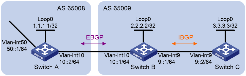
Configuration procedure
1. Configure IP addresses for interfaces. (Details not shown.)
2. Configure IBGP:
# Configure Switch B.
<SwitchB> system-view
[SwitchB] bgp 65009
[SwitchB-bgp-default] router-id 2.2.2.2
[SwitchB-bgp-default] peer 9::2 as-number 65009
[SwitchB-bgp-default] address-family ipv6
[SwitchB-bgp-default-ipv6] peer 9::2 enable
[SwitchB-bgp-default-ipv6] quit
# Configure Switch C.
<SwitchC> system-view
[SwitchC] bgp 65009
[SwitchC-bgp-default] router-id 3.3.3.3
[SwitchC-bgp-default] peer 9::1 as-number 65009
[SwitchC-bgp-default] address-family ipv6
[SwitchC-bgp-default-ipv6] peer 9::1 enable
3. Configure EBGP:
# Configure Switch A.
<SwitchA> system-view
[SwitchA] bgp 65008
[SwitchA-bgp-default] router-id 1.1.1.1
[SwitchA-bgp-default] peer 10::1 as-number 65009
[SwitchA-bgp-default] address-family ipv6
[SwitchA-bgp-default-ipv6] peer 10::1 enable
# Configure Switch B.
[SwitchB-bgp-default] peer 10::2 as-number 65008
[SwitchB-bgp-default] address-family ipv6
[SwitchB-bgp-default-ipv6] peer 10::2 enable
4. Inject network routes to the BGP routing table:
# Configure Switch A.
[SwitchA-bgp-default-ipv6] network 10:: 64
[SwitchA-bgp-default-ipv6] network 50:: 64
[SwitchA-bgp-default-ipv6] quit
[SwitchA-bgp-default] quit
# Configure Switch B.
[SwitchB-bgp-default-ipv6] network 10:: 64
[SwitchB-bgp-default-ipv6] network 9:: 64
[SwitchB-bgp-default-ipv6] quit
[SwitchB-bgp-default] quit
# Configure Switch C.
[SwitchC-bgp-default-ipv6] network 9:: 64
[SwitchC-bgp-default-ipv6] quit
[SwitchC-bgp-default] quit
Verifying the configuration
# Display IPv6 BGP peer information on Switch B.
[SwitchB] display bgp peer ipv6
BGP local router ID: 2.2.2.2
Local AS number: 65009
Total number of peers: 2 Peers in established state: 2
* - Dynamically created peer
Peer AS MsgRcvd MsgSent OutQ PrefRcv Up/Down State
9::2 65009 41 43 0 1 00:29:00 Established
10::2 65008 38 38 0 2 00:27:20 Established
The output shows that Switch A and Switch B have established an EBGP connection, and Switch B and Switch C have established an IBGP connection.
# Display IPv6 BGP routing table information on Switch A.
[SwitchA] display bgp routing-table ipv6
Total number of routes: 4
BGP local router ID is 1.1.1.1
Status codes: * - valid, > - best, d - dampened, h - history,
s - suppressed, S - stale, i - internal, e - external
a – additional-path
Origin: i - IGP, e - EGP, ? - incomplete
* >e Network : 9:: PrefixLen : 64
NextHop : 10::1 LocPrf :
PrefVal : 0 OutLabel : NULL
MED : 0
Path/Ogn: 65009i
* > Network : 10:: PrefixLen : 64
NextHop : :: LocPrf :
PrefVal : 32768 OutLabel : NULL
MED : 0
Path/Ogn: i
* e Network : 10:: PrefixLen : 64
NextHop : 10::1 LocPrf :
PrefVal : 0 OutLabel : NULL
MED : 0
Path/Ogn: 65009i
* > Network : 50:: PrefixLen : 64
NextHop : :: LocPrf :
PrefVal : 32768 OutLabel : NULL
MED : 0
Path/Ogn: i
The output shows that Switch A has learned routing information of AS 65009.
# Display IPv6 BGP routing table information on Switch C.
[SwitchC] display bgp routing-table ipv6
Total number of routes: 4
BGP local router ID is 3.3.3.3
Status codes: * - valid, > - best, d - dampened, h - history,
s - suppressed, S - stale, i - internal, e - external
a – additional-path
Origin: i - IGP, e - EGP, ? - incomplete
* > Network : 9:: PrefixLen : 64
NextHop : :: LocPrf :
PrefVal : 32768 OutLabel : NULL
MED : 0
Path/Ogn: i
* i Network : 9:: PrefixLen : 64
NextHop : 9::1 LocPrf : 100
PrefVal : 0 OutLabel : NULL
MED : 0
Path/Ogn: i
* >i Network : 10:: PrefixLen : 64
NextHop : 9::1 LocPrf : 100
PrefVal : 0 OutLabel : NULL
MED : 0
Path/Ogn: i
* >i Network : 50:: PrefixLen : 64
NextHop : 10::2 LocPrf : 100
PrefVal : 0 OutLabel : NULL
MED : 0
Path/Ogn: 65008i
The output shows that Switch C has learned the route 50::/64.
# Verify that Switch C can ping hosts on network 50::/64. (Details not shown.)
IPv6 BGP route reflector configuration example
Network requirements
As shown in Figure 34, run EBGP between Switch A and Switch B, run IBGP between Switch C and Switch B, and between Switch C and Switch D.
Configure Switch C as a route reflector with clients Switch B and Switch D.
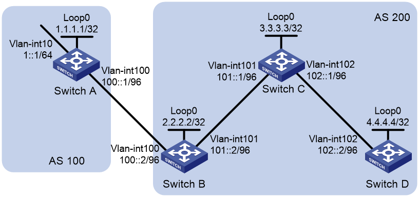
Configuration procedure
1. Configure IPv6 addresses for interfaces and IPv4 addresses for loopback interfaces. (Details not shown.)
2. Configure IBGP and EBGP connections and advertise network routes through IPv6 BGP:
# Configure Switch A.
<SwitchA> system-view
[SwitchA] bgp 100
[SwitchA-bgp-default] router-id 1.1.1.1
[SwitchA-bgp-default] peer 100::2 as-number 200
[SwitchA-bgp-default] address-family ipv6
[SwitchA-bgp-default-ipv6] peer 100::2 enable
[SwitchA-bgp-default-ipv6] network 1:: 64
[SwitchA-bgp-default-ipv6] network 100:: 96
[SwitchA-bgp-default-ipv6] quit
[SwitchA-bgp-default] quit
# Configure Switch B.
<SwitchB> system-view
[SwitchB] bgp 200
[SwitchB-bgp-default] router-id 2.2.2.2
[SwitchB-bgp-default] peer 100::1 as-number 100
[SwitchB-bgp-default] peer 101::1 as-number 200
[SwitchB-bgp-default] address-family ipv6
[SwitchB-bgp-default-ipv6] peer 100::1 enable
[SwitchB-bgp-default-ipv6] peer 101::1 enable
[SwitchB-bgp-default-ipv6] peer 101::1 next-hop-local
[SwitchB-bgp-default-ipv6] network 100:: 96
[SwitchB-bgp-default-ipv6] network 101:: 96
[SwitchB-bgp-default-ipv6] quit
[SwitchB-bgp-default] quit
# Configure Switch C.
<SwitchC> system-view
[SwitchC] bgp 200
[SwitchC-bgp-default] router-id 3.3.3.3
[SwitchC-bgp-default] peer 101::2 as-number 200
[SwitchC-bgp-default] peer 102::2 as-number 200
[SwitchC-bgp-default] address-family ipv6
[SwitchC-bgp-default-ipv6] peer 101::2 enable
[SwitchC-bgp-default-ipv6] peer 102::2 enable
[SwitchC-bgp-default-ipv6] network 101:: 96
[SwitchC-bgp-default-ipv6] network 102:: 96
# Configure Switch D.
<SwitchD> system-view
[SwitchD] bgp 200
[SwitchD-bgp-default] router-id 4.4.4.4
[SwitchD-bgp-default] peer 102::1 as-number 200
[SwitchD-bgp-default] address-family ipv6
[SwitchD-bgp-default-ipv6] peer 102::1 enable
[SwitchD-bgp-default-ipv6] network 102:: 96
3. Configure Switch C as a route reflector, and configure Switch B and Switch D as its clients.
[SwitchC-bgp-default-ipv6] peer 101::2 reflect-client
[SwitchC-bgp-default-ipv6] peer 102::2 reflect-client
[SwitchC-bgp-default-ipv6] quit
[SwitchC-bgp-default] quit
Verifying the configuration
# Execute the display bgp routing-table ipv6 command on Switch D.
[SwitchD] display bgp routing-table ipv6
Total number of routes: 5
BGP local router ID is 4.4.4.4
Status codes: * - valid, > - best, d - dampened, h - history,
s - suppressed, S - stale, i - internal, e - external
a – additional-path
Origin: i - IGP, e - EGP, ? - incomplete
* >i Network : 1:: PrefixLen : 64
NextHop : 101::2 LocPrf : 100
PrefVal : 0 OutLabel : NULL
MED : 0
Path/Ogn: 100i
* >i Network : 100:: PrefixLen : 96
NextHop : 101::2 LocPrf : 100
PrefVal : 0 OutLabel : NULL
MED : 0
Path/Ogn: i
* >i Network : 101:: PrefixLen : 96
NextHop : 102::1 LocPrf : 100
PrefVal : 0 OutLabel : NULL
MED : 0
Path/Ogn: i
* > Network : 102:: PrefixLen : 96
NextHop : :: LocPrf :
PrefVal : 32768 OutLabel : NULL
MED : 0
Path/Ogn: i
* i Network : 102:: PrefixLen : 96
NextHop : 102::1 LocPrf : 100
PrefVal : 0 OutLabel : NULL
MED : 0
Path/Ogn: i
The output shows that Switch D has learned the network 1::/64 from Switch C through route reflection.
6PE configuration example
Network requirements
As shown in Figure 35, use 6PE to connect two isolated IPv6 networks over an IPv4/MPLS network.
· The ISP uses OSPF as the IGP.
· PE 1 and PE 2 are edge devices of the ISP, and establish an IPv4 IBGP connection between them.
· CE 1 and CE 2 are edge devices of the IPv6 networks, and they connect the IPv6 networks to the ISP.
· A CE and a PE exchange IPv6 packets through IPv6 static routing.
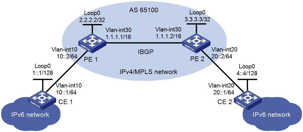
Configuration procedure
1. Configure IPv6 addresses and IPv4 addresses for interfaces. (Details not shown.)
2. Configure PE 1:
# Enable LDP globally, and configure the LSP generation policy.
<PE1> system-view
[PE1] mpls lsr-id 2.2.2.2
[PE1] mpls ldp
[PE1-ldp] lsp-trigger all
[PE1-ldp] quit
# Enable MPLS and LDP on VLAN-interface 30.
[PE1] interface vlan-interface 30
[PE1-Vlan-interface30] mpls enable
[PE1-Vlan-interface30] mpls ldp enable
[PE1-Vlan-interface30] quit
# Configure IBGP, enable the peer's 6PE capabilities, and redistribute IPv6 direct and static routes.
[PE1] bgp 65100
[PE1-bgp-default] router-id 2.2.2.2
[PE1-bgp-default] peer 3.3.3.3 as-number 65100
[PE1-bgp-default] peer 3.3.3.3 connect-interface loopback 0
[PE1-bgp-default] address-family ipv6
[PE1-bgp-default-ipv6] import-route direct
[PE1-bgp-default-ipv6] import-route static
[PE1-bgp-default-ipv6] peer 3.3.3.3 enable
[PE1-bgp-default-ipv6] peer 3.3.3.3 label-route-capability
[PE1-bgp-default-ipv6] quit
[PE1-bgp-default] quit
# Configure a static route to CE 1.
[PE1] ipv6 route-static 1::1 128 10::1
# Configure OSPF for the ISP.
[PE1] ospf
[PE1-ospf-1] area 0
[PE1-ospf-1-area-0.0.0.0] network 2.2.2.2 0.0.0.0
[PE1-ospf-1-area-0.0.0.0] network 1.1.0.0 0.0.255.255
[PE1-ospf-1-area-0.0.0.0] quit
[PE1-ospf-1] quit
3. Configure PE 2:
# Enable LDP globally, and configure the LSP generation policy.
<PE2> system-view
[PE2] mpls lsr-id 3.3.3.3
[PE2] mpls ldp
[PE2-mpls-ldp] lsp-trigger all
[PE2-mpls-ldp] quit
# Enable MPLS and LDP on VLAN-interface 30.
[PE2] interface vlan-interface 30
[PE2-Vlan-interface30] mpls enable
[PE2-Vlan-interface30] mpls ldp enable
[PE2-Vlan-interface30] quit
# Configure IBGP, enable the peer's 6PE capabilities, and redistribute IPv6 direct and static routes.
[PE2] bgp 65100
[PE2-bgp-default] router-id 3.3.3.3
[PE2-bgp-default] peer 2.2.2.2 as-number 65100
[PE2-bgp-default] peer 2.2.2.2 connect-interface loopback 0
[PE2-bgp-default] address-family ipv6
[PE2-bgp-default-ipv6] import-route direct
[PE2-bgp-default-ipv6] import-route static
[PE2-bgp-default-ipv6] peer 2.2.2.2 enable
[PE2-bgp-default-ipv6] peer 2.2.2.2 label-route-capability
[PE2-bgp-default-ipv6] quit
[PE2-bgp-default] quit
# Configure the static route to CE 2.
[PE2] ipv6 route-static 4::4 128 20::1
# Configure OSPF for the ISP.
[PE2] ospf
[PE2-ospf-1] area 0
[PE2-ospf-1-area-0.0.0.0] network 3.3.3.3 0.0.0.0
[PE2-ospf-1-area-0.0.0.0] network 1.1.0.0 0.0.255.255
[PE2-ospf-1-area-0.0.0.0] quit
[PE2-ospf-1] quit
4. Configure a static route on CE 1, with PE 1 as the default next hop.
<CE1> system-view
[CE1] ipv6 route-static :: 0 10::2
5. Configure a static route on CE 2, with PE 2 as the default next hop.
<CE2> system-view
[CE2] ipv6 route-static :: 0 20::2
Verifying the configuration
# Display the IPv6 BGP routing tables on PE 1 and PE 2. The output shows that each of them has two IPv6 network routes. The following shows the output on PE 1:
[PE1] display bgp routing-table ipv6
Total number of routes: 5
BGP local router ID is 2.2.2.2
Status codes: * - valid, > - best, d - dampened, h - history,
s - suppressed, S - stale, i - internal, e - external
a – additional-path
Origin: i - IGP, e - EGP, ? - incomplete
* > Network : 1::1 PrefixLen : 128
NextHop : 10::1 LocPrf :
PrefVal : 32768 OutLabel : NULL
MED : 0
Path/Ogn: ?
* >i Network : 4::4 PrefixLen : 128
NextHop : ::FFFF:3.3.3.3 LocPrf : 100
PrefVal : 0 OutLabel : 1279
MED : 0
Path/Ogn: ?
* > Network : 10:: PrefixLen : 64
NextHop : :: LocPrf :
PrefVal : 32768 OutLabel : NULL
MED : 0
Path/Ogn: ?
* > Network : 10::2 PrefixLen : 128
NextHop : ::1 LocPrf :
PrefVal : 32768 OutLabel : NULL
MED : 0
Path/Ogn: ?
* >i Network : 20:: PrefixLen : 64
NextHop : ::FFFF:3.3.3.3 LocPrf : 100
PrefVal : 0 OutLabel : 1278
MED : 0
Path/Ogn: ?
# Verify that CE 1 can ping the IPv6 address 4::4 (loopback interface address) of CE 2. (Details not shown.)
BFD for IPv6 BGP configuration example
Network requirements
As shown in Figure 36, configure OSPFv3 as the IGP in AS 200.
· Establish two IBGP connections between Switch A and Switch C. When both paths operate correctly, Switch C uses the path Switch A<—>Switch B<—>Switch C to exchange packets with network 1200::0/64.
· Configure BFD over the path. When the path fails, BFD can quickly detect the failure and notify it to IPv6 BGP. Then, the path Switch A<—>Switch D<—>Switch C takes effect immediately.
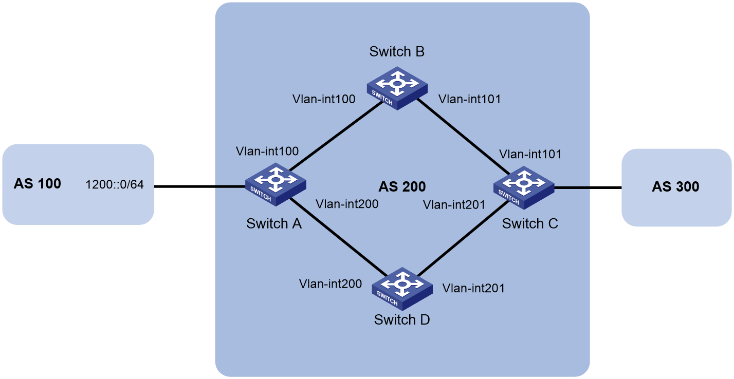
Table 7 Interface and IP address assignment
|
Device |
Interface |
IP address |
Device |
Interface |
IP address |
|
Switch A |
Vlan-int100 |
3000::1/64 |
Switch C |
Vlan-int101 |
3001::3/64 |
|
|
Vlan-int200 |
2000::1/64 |
|
Vlan-int201 |
2001::3/64 |
|
Switch B |
Vlan-int100 |
3000::2/64 |
Switch D |
Vlan-int200 |
2000::2/64 |
|
|
Vlan-int101 |
3001::2/64 |
|
Vlan-int201 |
2001::2/64 |
Configuration procedure
1. Configure IPv6 addresses for interfaces. (Details not shown.)
2. Configure OSPFv3 so that Switch A and Switch C can reach each other. (Details not shown.)
3. Configure IPv6 BGP on Switch A:
# Establish two IBGP connections to Switch C.
<SwitchA> system-view
[SwitchA] bgp 200
[SwitchA-bgp-default] router-id 1.1.1.1
[SwitchA-bgp-default] peer 3001::3 as-number 200
[SwitchA-bgp-default] peer 2001::3 as-number 200
[SwitchA-bgp-default] address-family ipv6
[SwitchA-bgp-default-ipv6] peer 3001::3 enable
[SwitchA-bgp-default-ipv6] peer 2001::3 enable
[SwitchA-bgp-default-ipv6] quit
# Create IPv6 basic ACL 2000 to permit 1200::0/64 to pass.
[SwitchA] acl ipv6 basic 2000
[SwitchA-acl-ipv6-basic-2000] rule permit source 1200:: 64
[SwitchA-acl-ipv6-basic-2000] quit
# Create two routing policies to set the MED for route 1200::0/64. The policy apply_med_50 sets the MED to 50, and the policy apply_med_100 sets the MED to 100.
[SwitchA] route-policy apply_med_50 permit node 10
[SwitchA-route-policy-apply_med_50-10] if-match ipv6 address acl 2000
[SwitchA-route-policy-apply_med_50-10] apply cost 50
[SwitchA-route-policy-apply_med_50-10] quit
[SwitchA] route-policy apply_med_100 permit node 10
[SwitchA-route-policy-apply_med_100-10] if-match ipv6 address acl 2000
[SwitchA-route-policy-apply_med_100-10] apply cost 100
[SwitchA-route-policy-apply_med_100-10] quit
# Apply routing policy apply_med_50 to routes outgoing to peer 3001::3, and apply routing policy apply_med_100 to routes outgoing to peer 2001::3.
[SwitchA] bgp 200
[SwitchA-bgp-default] address-family ipv6 unicast
[SwitchA-bgp-default-ipv6] peer 3001::3 route-policy apply_med_50 export
[SwitchA-bgp-default-ipv6] peer 2001::3 route-policy apply_med_100 export
[SwitchA-bgp-default-ipv6] quit
# Enable BFD for peer 3001::3.
[SwitchA-bgp-default] peer 3001::3 bfd
[SwitchA-bgp-default] quit
4. Configure IPv6 BGP on Switch C:
# Establish two IBGP connections to Switch A.
<SwitchC> system-view
[SwitchC] bgp 200
[SwitchC-bgp-default] router-id 3.3.3.3
[SwitchC-bgp-default] peer 3000::1 as-number 200
[SwitchC-bgp-default] peer 2000::1 as-number 200
[SwitchC-bgp-default] address-family ipv6
[SwitchC-bgp-default-ipv6] peer 3000::1 enable
[SwitchC-bgp-default-ipv6] peer 2000::1 enable
[SwitchC-bgp-default-ipv6] quit
# Enable BFD for peer 3001::1.
[SwitchC-bgp-default] peer 3000::1 bfd
[SwitchC-bgp-default] quit
[SwitchC] quit
Verifying the configuration
# Display detailed BFD session information on Switch C.
<SwitchC> display bfd session verbose
Total Session Num: 1 Up Session Num: 1 Init Mode: Active
IPv6 Session Working Under Ctrl Mode:
Local Discr: 513 Remote Discr: 513
Source IP: 3001::3
Destination IP: 3000::1
Session State: Up Interface: N/A
Min Tx Inter: 500ms Act Tx Inter: 500ms
Min Rx Inter: 500ms Detect Inter: 2500ms
Rx Count: 13 Tx Count: 14
Connect Type: Indirect Running Up for: 00:00:05
Hold Time: 2243ms Auth mode: None
Detect Mode: Async Slot: 0
Protocol: BGP4+
Version:1
Diag Info: No Diagnostic
The output shows that a BFD session has been established between Switch A and Switch C.
# Display BGP peer information on Switch C.
<SwitchC> display bgp peer ipv6
BGP local router ID: 3.3.3.3
Local AS number: 200
Total number of peers: 2 Peers in established state: 2
* - Dynamically created peer
Peer AS MsgRcvd MsgSent OutQ PrefRcv Up/Down State
2000::1 200 8 8 0 0 00:04:45 Established
3000::1 200 5 4 0 0 00:01:53 Established
The output shows that Switch C has established two BGP connections with Switch A, and both connections are in Established state.
# Display route 1200::0/64 on Switch C.
<SwitchC> display ipv6 routing-table 1200::0 64 verbose
Summary count : 1
Destination: 1200::/64
Protocol: BGP4+ Process ID: 0
SubProtID: 0x1 Age: 00h01m07s
Cost: 50 Preference: 255
IpPre: N/A QosLocalID: N/A
Tag: 0 State: Active Adv
OrigTblID: 0x1 OrigVrf: default-vrf
TableID: 0xa OrigAs: 0
NibID: 0x25000001 LastAs: 0
AttrID: 0x1 Neighbor: 3000::1
Flags: 0x10060 OrigNextHop: 3000::1
Label: NULL RealNextHop: FE80::20C:29FF:FE4A:3873
BkLabel: NULL BkNextHop: N/A
Tunnel ID: Invalid Interface: Vlan-interface101
BkTunnel ID: Invalid BkInterface: N/A
The output shows that Switch C communicates with network 1200::0/64 through the path Switch C<—>Switch B<—>Switch A.
# Break down the path Switch C<—>Switch B<—>Switch A and then display route 1200::0/64 on Switch C.
<SwitchC> display ipv6 routing-table 1200::0 64 verbose
Summary count : 1
Destination: 1200::/64
Protocol: BGP4+ Process ID: 0
SubProtID: 0x1 Age: 00h00m57s
Cost: 100 Preference: 255
IpPre: N/A QosLocalID: N/A
Tag: 0 State: Active Adv
OrigTblID: 0x1 OrigVrf: default-vrf
TableID: 0xa OrigAs: 0
NibID: 0x25000000 LastAs: 0
AttrID: 0x0 Neighbor: 2000::1
Flags: 0x10060 OrigNextHop: 2000::1
Label: NULL RealNextHop: FE80::20C:29FF:FE40:715
BkLabel: NULL BkNextHop: N/A
Tunnel ID: Invalid Interface: Vlan-interface201
BkTunnel ID: Invalid BkInterface: N/A
The output shows that Switch C communicates with network 1200::0/64 through the path Switch C<—>Switch D<—>Switch A.
IPsec for IPv6 BGP packets configuration example
Network requirements
As shown in Figure 37, all switches run IPv6 BGP. Establish an IBGP connection between Switch A and Switch B, and establish an EBGP connection between Switch B and Switch C.
To enhance security, configure IPsec to protect IPv6 BGP packets.
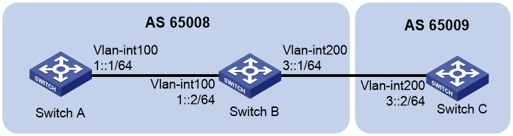
Configuration procedure
1. Configure IPv6 addresses for interfaces. (Details not shown.)
2. Establish an IBGP connection between Switch A and Switch B:
# Configure Switch A.
<SwitchA> system-view
[SwitchA] bgp 65008
[SwitchA-bgp-default] router-id 1.1.1.1
[SwitchA-bgp-default] group ibgp internal
[SwitchA-bgp-default] peer 1::2 group ibgp
[SwitchA-bgp-default] address-family ipv6 unicast
[SwitchA-bgp-default-ipv6] peer ibgp enable
[SwitchA-bgp-default-ipv6] quit
[SwitchA-bgp-default] quit
# Configure Switch B.
<SwitchB> system-view
[SwitchB] bgp 65008
[SwitchB-bgp-default] router-id 2.2.2.2
[SwitchB-bgp-default] group ibgp internal
[SwitchB-bgp-default] peer 1::1 group ibgp
[SwitchB-bgp-default] address-family ipv6 unicast
[SwitchB-bgp-default-ipv6] peer ibgp enable
[SwitchB-bgp-default-ipv6] quit
3. Establish an EBGP connection between Switch B and Switch C:
# Configure Switch C.
<SwitchC> system-view
[SwitchC] bgp 65009
[SwitchC-bgp-default] router-id 3.3.3.3
[SwitchC-bgp-default] group ebgp external
[SwitchC-bgp-default] peer 3::1 as-number 65008
[SwitchC-bgp-default] peer 3::1 group ebgp
[SwitchC-bgp-default] address-family ipv6 unicast
[SwitchC-bgp-default-ipv6] peer ebgp enable
[SwitchC-bgp-default-ipv6] quit
[SwitchC-bgp-default] quit
# Configure Switch B.
[SwitchB-bgp-default] group ebgp external
[SwitchB-bgp-default] peer 3::2 as-number 65009
[SwitchB-bgp-default] peer 3::2 group ebgp
[SwitchB-bgp-default] address-family ipv6 unicast
[SwitchB-bgp-default-ipv6] peer ebgp enable
[SwitchB-bgp-default-ipv6] quit
[SwitchB-bgp-default] quit
4. Configure IPsec transform sets and IPsec profiles:
# On Switch A, create an IPsec transform set named tran1.
[SwitchA] ipsec transform-set tran1
# Set the encapsulation mode to transport mode.
[SwitchA-ipsec-transform-set-tran1] encapsulation-mode transport
# Set the security protocol to ESP, the encryption algorithm to DES, and authentication algorithm to SHA1.
[SwitchA-ipsec-transform-set-tran1] esp encryption-algorithm des
[SwitchA-ipsec-transform-set-tran1] esp authentication-algorithm sha1
[SwitchA-ipsec-transform-set-tran1] quit
# Create an IPsec profile named policy001, and specify the manual mode for it.
[SwitchA] ipsec profile policy001 manual
# Use IPsec transform set tran1.
[SwitchA-ipsec-profile-policy001-manual] transform-set tran1
# Set the SPIs of the inbound and outbound SAs to 12345.
[SwitchA-ipsec-profile-policy001-manual] sa spi outbound esp 12345
[SwitchA-ipsec-profile-policy001-manual] sa spi inbound esp 12345
# Set the keys for the inbound and outbound SAs using ESP to abcdefg.
[SwitchA-ipsec-profile-policy001-manual] sa string-key outbound esp simple abcdefg
[SwitchA-ipsec-profile-policy001-manual] sa string-key inbound esp simple abcdefg
[SwitchA-ipsec-profile-policy001-manual] quit
# On Switch B, create an IPsec transform set named tran1.
[SwitchB] ipsec transform-set tran1
# Set the encapsulation mode to transport mode.
[SwitchB-ipsec-transform-set-tran1] encapsulation-mode transport
# Set the security protocol to ESP, the encryption algorithm to DES, and authentication algorithm to SHA1.
[SwitchB-ipsec-transform-set-tran1] esp encryption-algorithm des
[SwitchB-ipsec-transform-set-tran1] esp authentication-algorithm sha1
[SwitchB-ipsec-transform-set-tran1] quit
# Create IPsec profile named policy001, and specify the manual mode for it.
[SwitchB] ipsec profile policy001 manual
# Use IPsec transform set tran1.
[SwitchB-ipsec-profile-policy001-manual] transform-set tran1
# Set the SPIs of the inbound and outbound SAs to 12345.
[SwitchB-ipsec-profile-policy001-manual] sa spi outbound esp 12345
[SwitchB-ipsec-profile-policy001-manual] sa spi inbound esp 12345
# Set the keys for the inbound and outbound SAs using ESP to abcdefg.
[SwitchB-ipsec-profile-policy001-manual] sa string-key outbound esp simple abcdefg
[SwitchB-ipsec-profile-policy001-manual] sa string-key inbound esp simple abcdefg
[SwitchB-ipsec-profile-policy001-manual] quit
# Create an IPsec transform set named tran2.
[SwitchB] ipsec transform-set tran2
# Set the encapsulation mode to transport mode.
[SwitchB-ipsec-transform-set-tran2] encapsulation-mode transport
# Set the security protocol to ESP, the encryption algorithm to DES, and authentication algorithm to SHA1.
[SwitchB-ipsec-transform-set-tran2] esp encryption-algorithm des
[SwitchB-ipsec-transform-set-tran2] esp authentication-algorithm sha1
[SwitchB-ipsec-transform-set-tran2] quit
# Create IPsec profile named policy002, and specify the manual mode for it.
[SwitchB] ipsec profile policy002 manual
# Use IPsec transform set tran2.
[SwitchB-ipsec-profile-policy002-manual] transform-set tran2
# Set the SPIs of the inbound and outbound SAs to 54321.
[SwitchB-ipsec-profile-policy002-manual] sa spi outbound esp 54321
[SwitchB-ipsec-profile-policy002-manual] sa spi inbound esp 54321
# Set the keys for the inbound and outbound SAs using ESP to gfedcba.
[SwitchB-ipsec-profile-policy002-manual] sa string-key outbound esp simple gfedcba
[SwitchB-ipsec-profile-policy002-manual] sa string-key inbound esp simple gfedcba
[SwitchB-ipsec-profile-policy002-manual] quit
# On Switch C, create an IPsec transform set named tran2.
[SwitchC] ipsec transform-set tran2
# Set the encapsulation mode to transport mode.
[SwitchC-ipsec-transform-set-tran2] encapsulation-mode transport
# Set the security protocol to ESP, the encryption algorithm to DES, and authentication algorithm to SHA1.
[SwitchC-ipsec-transform-set-tran2] esp encryption-algorithm des
[SwitchC-ipsec-transform-set-tran2] esp authentication-algorithm sha1
[SwitchC-ipsec-transform-set-tran2] quit
# Create IPsec profile named policy002, and specify the manual mode for it.
[SwitchC] ipsec profile policy002 manual
# Use IPsec transform set tran2.
[SwitchC-ipsec-profile-policy002-manual] transform-set tran2
# Set the SPIs of the inbound and outbound SAs to 54321.
[SwitchC-ipsec-profile-policy002-manual] sa spi outbound esp 54321
[SwitchC-ipsec-profile-policy002-manual] sa spi inbound esp 54321
# Set the keys for the inbound and outbound SAs using ESP to gfedcba.
[SwitchC-ipsec-profile-policy002-manual] sa string-key outbound esp simple gfedcba
[SwitchC-ipsec-profile-policy002-manual] sa string-key inbound esp simple gfedcba
[SwitchC-ipsec-profile-policy002-manual] quit
5. Configure IPsec to protect IPv6 BGP packets between Switch A and Switch B:
# Configure Switch A.
[SwitchA] bgp 65008
[SwitchA-bgp-default] peer 1::2 ipsec-profile policy001
[SwitchA-bgp-default] quit
# Configure Switch B.
[SwitchB] bgp 65008
[SwitchB-bgp-default] peer 1::1 ipsec-profile policy001
[SwitchB-bgp-default] quit
6. Configure IPsec to protect IPv6 BGP packets between Router B and Switch C:
# Configure Switch C.
[SwitchC] bgp 65009
[SwitchC-bgp-default] peer ebgp ipsec-profile policy002
[SwitchC-bgp-default] quit
# Configure Switch B.
[SwitchB] bgp 65008
[SwitchB-bgp-default] peer ebgp ipsec-profile policy002
[SwitchB-bgp-default] quit
Verifying the configuration
# Display detailed information about IPv6 BGP peers on Switch B.
[SwitchB] display bgp peer ipv6 verbose
Peer: 1::1 Local: 2.2.2.2
Type: IBGP link
BGP version 4, remote router ID 1.1.1.1
BGP current state: Established, Up for 00h05m54s
BGP current event: KATimerExpired
BGP last state: OpenConfirm
Port: Local - 24896 Remote - 179
Configured: Active Hold Time: 180 sec Keepalive Time: 60 sec
Received : Active Hold Time: 180 sec
Negotiated: Active Hold Time: 180 sec Keepalive Time: 60 sec
Peer optional capabilities:
Peer support BGP multi-protocol extended
Peer support BGP route refresh capability
Peer support BGP route AS4 capability
Address family IPv6 Unicast: advertised and received
InQ updates: 0, OutQ updates: 0
NLRI statistics:
Rcvd: UnReach NLRI 0, Reach NLRI 0
Sent: UnReach NLRI 0, Reach NLRI 3
Message statistics:
Msg type Last rcvd time/ Current rcvd count/ History rcvd count/
Last sent time Current sent count History sent count
Open 18:59:15-2013.4.24 1 1
18:59:15-2013.4.24 1 2
Update - 0 0
18:59:16-2013.4.24 1 1
Notification - 0 0
18:59:15-2013.4.24 0 1
Keepalive 18:59:15-2013.4.24 1 1
18:59:15-2013.4.24 1 1
RouteRefresh - 0 0
- 0 0
Total - 2 2
- 3 5
Maximum allowed prefix number: 4294967295
Threshold: 75%
Minimum time between advertisements is 15 seconds
Optional capabilities:
Multi-protocol extended capability has been enabled
Route refresh capability has been enabled
Peer preferred value: 0
IPsec profile name: policy001
Routing policy configured:
No routing policy is configured
Peer: 3::2 Local: 2.2.2.2
Type: EBGP link
BGP version 4, remote router ID 3.3.3.3
BGP current state: Established, Up for 00h05m00s
BGP current event: KATimerExpired
BGP last state: OpenConfirm
Port: Local - 24897 Remote - 179
Configured: Active Hold Time: 180 sec Keepalive Time: 60 sec
Received : Active Hold Time: 180 sec
Negotiated: Active Hold Time: 180 sec Keepalive Time: 60 sec
Peer optional capabilities:
Peer support BGP multi-protocol extended
Peer support BGP route refresh capability
Peer support BGP route AS4 capability
Address family IPv6 Unicast: advertised and received
Received: Total 8 messages, Update messages 1
Sent: Total 8 messages, Update messages 1
Maximum allowed prefix number: 4294967295
Threshold: 75%
Minimum time between advertisements is 30 seconds
Optional capabilities:
Multi-protocol extended capability has been enabled
Route refresh capability has been enabled
Peer preferred value: 0
IPsec profile name: policy002
Routing policy configured:
No routing policy is configured
IPv6 BGP FRR configuration example
Network requirements
As shown in Figure 38, configure BGP FRR so that when Link B fails, BGP uses Link A to forward traffic.
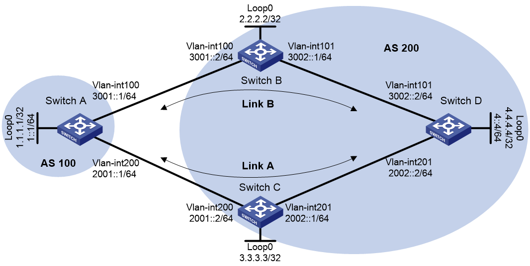
Configuration procedure
1. Configure IPv6 addresses for interfaces. (Details not shown.)
2. Configure OSPFv3 in AS 200 to ensure connectivity among Switch B, Switch C, and Switch D. (Details not shown.)
3. Configure BGP connections:
# Configure Switch A to establish EBGP sessions to Switch B and Switch C, and advertise network 1::/64.
<SwitchA> system-view
[SwitchA] bgp 100
[SwitchA] router-id 1.1.1.1
[SwitchA-bgp-default] peer 3001::2 as-number 200
[SwitchA-bgp-default] peer 2001::2 as-number 200
[SwitchA-bgp-default] address-family ipv6 unicast
[SwitchA-bgp-default-ipv6] peer 3001::2 enable
[SwitchA-bgp-default-ipv6] peer 2001::2 enable
[SwitchA-bgp-default-ipv6] network 1:: 64
[SwitchA-bgp-default-ipv6] quit
[SwitchA-bgp-default] quit
# Configure Switch B to establish an EBGP session to Switch A, and an IBGP session to Switch D.
<SwitchB> system-view
[SwitchB] bgp 200
[SwitchB] router-id 2.2.2.2
[SwitchB-bgp-default] peer 3001::1 as-number 100
[SwitchB-bgp-default] peer 3002::2 as-number 200
[SwitchB-bgp-default] address-family ipv6 unicast
[SwitchB-bgp-default-ipv6] peer 3001::1 enable
[SwitchB-bgp-default-ipv6] peer 3002::2 enable
[SwitchB-bgp-default-ipv6] peer 3002::2 next-hop-local
[SwitchB-bgp-default-ipv6] quit
[SwitchB-bgp-default] quit
# Configure Switch C to establish an EBGP session to Switch A, and an IBGP session to Switch D.
<SwitchC> system-view
[SwitchC] bgp 200
[SwitchC] router-id 3.3.3.3
[SwitchC-bgp-default] peer 2001::1 as-number 100
[SwitchC-bgp-default] peer 2002::2 as-number 200
[SwitchC-bgp-default] address-family ipv6 unicast
[SwitchC-bgp-default-ipv6] peer 2001::1 enable
[SwitchC-bgp-default-ipv6] peer 2002::2 enable
[SwitchC-bgp-default-ipv6] peer 2002::2 next-hop-local
[SwitchC-bgp-default-ipv6] quit
[SwitchC-bgp-default] quit
# Configure Switch D to establish IBGP sessions to Switch B and Switch C, and advertise network 4::/64.
<SwitchD> system-view
[SwitchD] bgp 200
[SwitchD-bgp-default] peer 3002::1 as-number 200
[SwitchD-bgp-default] peer 2002::1 as-number 200
[SwitchD-bgp-default] address-family ipv6 unicast
[SwitchD-bgp-default-ipv6] peer 3002::1 enable
[SwitchD-bgp-default-ipv6] peer 2002::1 enable
[SwitchD-bgp-default-ipv6] network 4:: 64
[SwitchD-bgp-default-ipv6] quit
[SwitchD-bgp-default] quit
4. Configure preferred values so Link B is used to forward traffic between Switch A and Switch D:
# Configure Switch A to set the preferred value to 100 for routes received from Switch B.
[SwitchA-bgp-default-ipv6] peer 3001::2 preferred-value 100
[SwitchA-bgp-default-ipv6] quit
[SwitchA-bgp-default] quit
# Configure Switch D to set the preferred value to 100 for routes received from Switch B.
[SwitchD-bgp-default-ipv6] peer 3002::1 preferred-value 100
[SwitchD-bgp-default-ipv6] quit
[SwitchD-bgp-default] quit
5. Configure BGP FRR:
# On Switch A, create routing policy frr to set a backup next hop 2001::2 (Switch C) for the route destined for 4::/64.
<SwitchA> system-view
[SwitchA] ipv6 prefix-list abc index 10 permit 4:: 64
[SwitchA] route-policy frr permit node 10
[SwitchA-route-policy] if-match ipv6 address prefix-list abc
[SwitchA-route-policy] apply ipv6 fast-reroute backup-nexthop 2001::2
[SwitchA-route-policy] quit
# Apply the routing policy to BGP FRR for BGP IPv6 unicast address family.
[SwitchA] bgp 100
[SwitchA-bgp-default] address-family ipv6 unicast
[SwitchA-bgp-default-ipv6] fast-reroute route-policy frr
[SwitchA-bgp-default-ipv6] quit
[SwitchA-bgp-default] quit
# On Switch D, create routing policy frr to set a backup next hop 2002::1 (Switch C) for the route destined for 1::/64.
<SwitchD> system-view
[SwitchD] ipv6 prefix-list abc index 10 permit 1:: 64
[SwitchD] route-policy frr permit node 10
[SwitchD-route-policy] if-match ipv6 address prefix-list abc
[SwitchD-route-policy] apply ipv6 fast-reroute backup-nexthop 2002::1
[SwitchD-route-policy] quit
# Apply the routing policy to BGP FRR for BGP IPv6 unicast address family.
[SwitchD] bgp 200
[SwitchD-bgp-default] address-family ipv6 unicast
[SwitchD-bgp-default-ipv6] fast-reroute route-policy frr
[SwitchD-bgp-default-ipv6] quit
[SwitchD-bgp-default] quit
Verifying the configuration
# Display detailed information about the route to 4::/64 on Switch A. The output shows the backup next hop for the route.
[SwitchA] display ipv6 routing-table 4:: 64 verbose
Summary count : 1
Destination: 4::/64
Protocol: BGP4+ Process ID: 0
SubProtID: 0x2 Age: 00h00m58s
Cost: 0 Preference: 255
IpPre: N/A QosLocalID: N/A
Tag: 0 State: Active Adv
OrigTblID: 0x0 OrigVrf: default-vrf
TableID: 0xa OrigAs: 200
NibID: 0x25000003 LastAs: 200
AttrID: 0x3 Neighbor: 3001::2
Flags: 0x10060 OrigNextHop: 3001::2
Label: NULL RealNextHop: 3001::2
BkLabel: NULL BkNextHop: 2001::2
Tunnel ID: Invalid Interface: Vlan-interface 100
BkTunnel ID: Invalid BkInterface: Vlan-interface 200
FtnIndex: 0x0
# Display detailed information about the route to 1::/64 on Switch D. The output shows the backup next hop for the route.
[SwitchD] display ipv6 routing-table 1:: 64 verbose
Summary count : 1
Destination: 1::/64
Protocol: BGP4+ Process ID: 0
SubProtID: 0x1 Age: 00h03m24s
Cost: 0 Preference: 255
IpPre: N/A QosLocalID: N/A
Tag: 0 State: Active Adv
OrigTblID: 0x0 OrigVrf: default-vrf
TableID: 0xa OrigAs: 100
NibID: 0x25000003 LastAs: 100
AttrID: 0x4 Neighbor: 3002::1
Flags: 0x10060 OrigNextHop: 3002::1
Label: NULL RealNextHop: 3002::1
BkLabel: NULL BkNextHop: 2002::1
Tunnel ID: Invalid Interface: Vlan-interface 101
BkTunnel ID: Invalid BkInterface: Vlan-interface 201
FtnIndex: 0x0
IPv6 multicast BGP configuration example
Network requirements
As shown in Figure 39, OSPFv3 runs within AS 100 and AS 200 to ensure intra-AS connectivity. IPv6 MBGP runs between the two ASs to exchange IPv6 unicast routes used for RPF check.
Enable Anycast RP on Switch A and Switch B.
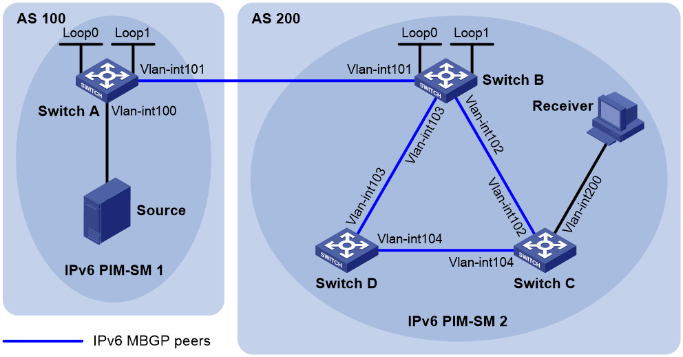
Table 8 Interface and IP address assignment
|
Device |
Interface |
IP address |
Device |
Interface |
IP address |
|
Source |
- |
1002::100/64 |
Switch B |
Vlan-int101 |
1001::2/64 |
|
Switch A |
Vlan-int100 |
1002::1/64 |
|
Vlan-int102 |
2001::1/64 |
|
|
Vlan-int101 |
1001::1/64 |
|
Vlan-int103 |
2002::1/64 |
|
|
Loop0 |
1:1::1/128 |
|
Loop0 |
1:1::1/128 |
|
|
Loop1 |
1:1::2/128 |
|
Loop1 |
2:2::2/128 |
|
Switch C |
Vlan-int200 |
3002::1/64 |
Switch D |
Vlan-int103 |
2002::2/64 |
|
|
Vlan-int102 |
2001::2/64 |
|
Vlan-int104 |
3001::2/64 |
|
|
Vlan-int104 |
3001::1/64 |
|
|
|
Configuration procedure
1. Configure IPv6 addresses for interfaces and configure OSPFv3 (this example uses OSPFv3 process 1) in AS 200 to ensure intra-AS connectivity. (Details not shown.)
2. Enable IPv6 multicast routing, IPv6 PIM-SM, and MLD, and configure BSR boundaries:
# On Switch A, enable IPv6 multicast routing globally, and enable IPv6 PIM-SM on interfaces.
<SwitchA> system-view
[SwitchA] ipv6 multicast routing
[SwitchA-mrib6] quit
[SwitchA] interface vlan-interface 100
[SwitchA-Vlan-interface100] ipv6 pim sm
[SwitchA-Vlan-interface100] quit
[SwitchA] interface vlan-interface 101
[SwitchA-Vlan-interface101] ipv6 pim sm
[SwitchA-Vlan-interface101] quit
[SwitchA] interface loopback 0
[SwitchA-LoopBack0] ipv6 pim sm
[SwitchA-LoopBack0] quit
# Configure Switch B and Switch D in the same way that Switch A was configured.
# On Switch C, enable IPv6 multicast routing globally.
<SwitchC> system-view
[SwitchC] ipv6 multicast routing
[SwitchC-mrib6] quit
# Enable IPv6 PIM-SM on interfaces, and enable MLD on VLAN-interface 200.
[SwitchC] interface vlan-interface 102
[SwitchC-Vlan-interface102] ipv6 pim sm
[SwitchC-Vlan-interface102] quit
[SwitchC] interface vlan-interface 104
[SwitchC-Vlan-interface104] ipv6 pim sm
[SwitchC-Vlan-interface104] quit
[SwitchC] interface vlan-interface 200
[SwitchC-Vlan-interface200] ipv6 pim sm
[SwitchC-Vlan-interface200] mld enable
[SwitchC-Vlan-interface200] quit
# Configure the BSR boundary on Switch A.
[SwitchA] interface vlan-interface 101
[SwitchA-Vlan-interface101] ipv6 pim bsr-boundary
[SwitchA-Vlan-interface101] quit
# Configure the BSR boundary on Switch B.
[SwitchB] interface vlan-interface 101
[SwitchB-Vlan-interface101] ipv6 pim bsr-boundary
[SwitchB-Vlan-interface101] quit
3. Enable Anycast RP, and specify C-BSR and C-RP:
# Configure Switch A.
[SwitchA] ipv6 pim
[SwitchA-pim6] anycast-rp 1:1::1 1:1::2
[SwitchA-pim6] anycast-rp 1:1::1 2:2::2
[SwitchA-pim6] c-bsr 1:1::1
[SwitchA-pim6] c-rp 1:1::1
[SwitchA-pim6] quit
# Configure Switch B.
[SwitchB] ipv6 pim
[SwitchB-pim6] anycast-rp 1:1::1 1:1::2
[SwitchB-pim6] anycast-rp 1:1::1 2:2::2
[SwitchB-pim6] c-bsr 1:1::1
[SwitchB-pim6] c-rp 1:1::1
[SwitchB-pim6] quit
4. Configure BGP to establish BGP IPv6 multicast peers and redistribute routes:
# On Switch A, establish an EBGP session to Switch B.
[SwitchA] bgp 100
[SwitchA-bgp-default] router-id 1.1.1.1
[SwitchA-bgp-default] peer 1001::2 as-number 200
# Enable exchange of IPv6 unicast routes used for RPF check with Switch B.
[SwitchA-bgp-default] address-family ipv6 multicast
[SwitchA-bgp-default-mul-ipv6] peer 1001::2 enable
# Redistribute direct routes into BGP.
[SwitchA-bgp-default-mul-ipv6] import-route direct
[SwitchA-bgp-default-mul-ipv6] quit
# On Switch B, establish an EBGP session to Switch A.
[SwitchB] bgp 200
[SwitchB-bgp-default] router-id 2.2.2.2
[SwitchB-bgp-default] peer 1001::1 as-number 100
# Enable exchange of IPv6 unicast routes used for RPF check with Switch B.
[SwitchB-bgp-default] address-family ipv6 multicast
[SwitchB-bgp-default-mul-ipv6] peer 1001::1 enable
# Redistribute OSPFv3 routes into BGP.
[SwitchB-bgp-default-mul-ipv6] import-route ospfv3 1
[SwitchB-bgp-default-mul-ipv6] quit
5. Establish BGP IPv6 unicast peer relationships between Switch A and Switch B and redistribute routes:
# On Switch A, enable BGP to exchange IPv6 unicast routes with Switch B, and redistribute direct routes into BGP.
[SwitchA-bgp-default] address-family ipv6 unicast
[SwitchA-bgp-default-ipv6] peer 1001::2 enable
[SwitchA-bgp-default-ipv6] import-route direct
[SwitchA-bgp-default-ipv6] quit
[SwitchA-bgp-default] quit
# On Switch B, enable BGP to exchange IPv6 unicast routes with Switch A, and redistribute direct routes into BGP.
[SwitchB-bgp-default] address-family ipv6 unicast
[SwitchB-bgp-default-ipv6] peer 1001::1 enable
[SwitchB-bgp-default-ipv6] import-route direct
[SwitchB-bgp-default-ipv6] quit
[SwitchB-bgp-default] quit
Verifying the configuration
# Verify the BGP IPv6 multicast peer information on Switch B.
[SwitchB] display bgp peer ipv6 multicast
BGP local router ID : 2.2.2.2
Local AS number : 200
Total number of peers : 3 Peers in established state : 3
Peer AS MsgRcvd MsgSent OutQ PrefRcv Up/Down State
1001::1 100 56 56 0 0 00:40:54 Established
# Verify the RPF information for the multicast source on Switch B.
[SwitchB] display ipv6 multicast rpf-info 1002::1
RPF information about source 1002::1:
RPF interface: Vlan-interface101, RPF neighbor: 1001::1
Referenced prefix/prefix length: 1002::/64
Referenced route type: mbgp
Route selection rule: preference-preferred
Load splitting rule: disable
Troubleshooting BGP
Symptom
The display bgp peer ipv4 unicast or display bgp peer ipv6 unicast command output shows that the state of the connection to a peer cannot become established.
Analysis
To become BGP peers, any two routers must establish a TCP connection using port 179 and exchange Open messages successfully.
Solution
1. To resolve the problem:
a. Use the display current-configuration command to verify the current configuration, and verify that the peer's AS number is correct.
b. Use the display bgp peer ipv4 unicast or display bgp peer ipv6 unicast command to verify that the peer's IP/IPv6 address is correct.
c. If a loopback interface is used, verify that the loopback interface is specified with the peer connect-interface command.
d. If the peer is a non-direct EBGP peer, verify that the peer ebgp-max-hop command is configured.
e. If the peer ttl-security hops command is configured, verify that the command is configured on the peer. Verify that the hop-count values configured on them are greater than the number of hops between them.
f. Verify that a valid route to the peer is available.
g. Use the ping command to verify the connectivity to the peer.
h. Use the display tcp verbose or display ipv6 tcp verbose command to verify the TCP connection.
i. Verify that no ACL rule is applied to disable TCP port 179.
2. If the problem persists, contact H3C Support.