- Table of Contents
- Related Documents
-
| Title | Size | Download |
|---|---|---|
| 01-Text | 15.64 MB |
Installation safety recommendations
Installation site requirements
Space and airflow requirements
Temperature and humidity requirements
Equipment room height requirements
Installing or removing the server
(Optional) Installing cable management brackets
Connecting a mouse, keyboard, and monitor
Removing the server from a rack
Powering on and powering off the server
Deploying and registering UIS Manager
Installing riser cards and PCIe modules
Installing an RC-3GPU-R4900-G3, RC-FHHL-2U-G3-1, or RS-3*FHHL-R4900 riser card and a PCIe module
Installing an RC-GPU/FHHL-2U-G3-1 riser card and a PCIe module
Installing an RC-2*FHFL-2U-G3 riser card and a PCIe module
Installing an RC-FHHL-2U-G3-2 riser card and a PCIe module
Installing an RC-2*LP-2U-G3 riser card and a PCIe module
Installing an RC-GPU/FHHL-2U-G3-2 or RC-2GPU-R4900-G3 riser card and a PCIe module
Installing storage controllers and power fail safeguard modules
Installing a Mezzanine storage controller and a power fail safeguard module
Installing a standard storage controller and a power fail safeguard module
Installing a GPU module without a power cord (standard chassis air baffle)
Installing a GPU module with a power cord (standard chassis air baffle)
Installing a GPU module with a power cord (GPU-dedicated chassis air baffle)
Installing an mLOM Ethernet adapter
Installing a PCIe Ethernet adapter
Installing SATA M.2 SSDs at the server front
Installing SATA M.2 SSDs at the server rear
Installing an NVMe SSD expander module
Installing the NVMe VROC module
Installing a front or rear drive cage
Installing the rear 2SFF drive cage
Installing the rear 4SFF drive cage
Installing the rear 2LFF drive cage
Installing the rear 4LFF drive cage
Installing a front 8SFF drive cage
Preparing for the installation
Installing a SATA optical drive
Preparing for the installation
Installing the SD-SFF-A SFF diagnostic panel
Installing the SD-SFF-B SFF diagnostic panel
Installing the SD-LFF-G3-A LFF diagnostic panel
Installing a serial label pull tab module
Installing and setting up a TCM or TPM
Installation and setup flowchart
Enabling the TCM or TPM in the BIOS
Configuring encryption in the operating system
Replacing a riser card and a PCIe module
Replacing an RC-Mezz-Riser-G3 Mezz PCIe riser card
Replacing a storage controller
Replacing the Mezzanine storage controller
Replacing a standard storage controller
Replacing the power fail safeguard module
Replacing the power fail safeguard module for the Mezzanine storage controller
Replacing the power fail safeguard module for a standard storage controller
Replacing a GPU module without a power cord or with a standard chassis air baffle
Replacing a GPU module with a power cord and a GPU-dedicated chassis air baffle
Replacing an mLOM Ethernet adapter
Replacing a PCIe Ethernet adapter
Replacing a M.2 transfer module and a SATA M.2 SSD
Replacing the front M.2 transfer module and a SATA M.2 SSD
Replacing the rear M.2 transfer module and a SATA M.2 SSD
Replacing the dual SD card extended module
Replacing an NVMe SSD expander module
Replacing the drive expander module
Replacing the SATA optical drive
Replacing the diagnostic panel
Replacing the serial label pull tab module
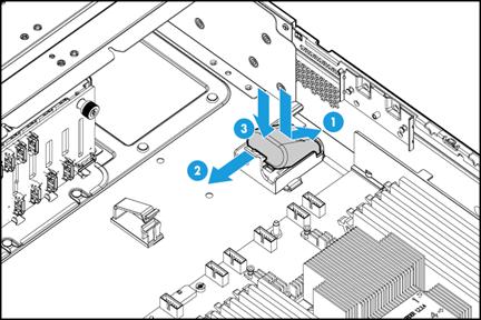
Replacing the chassis-open alarm module
Removing the chassis-open alarm module
Installing the chassis-open alarm module
Replacing the right chassis ear
Replacing the left chassis ear
Connecting the flash card and the supercapacitor of the power fail safeguard module
Connecting the flash card on the Mezzanine storage controller
Connecting the flash card on a standard storage controller
Connecting the power cord of a GPU module
Connecting the NCSI cable for a PCIe Ethernet adapter
Connecting the SATA M.2 SSD cable
Connecting the front SATA M.2 SSD cable
Connecting the rear SATA M.2 SSD cable
Connecting the SATA optical drive cable
Connecting the front I/O component cable assembly
Connecting the cable for the front VGA and USB 2.0 connectors on the left chassis ear
Connecting the diagnostic panel cable
Monitoring the temperature and humidity in the equipment room
Appendix A Server specifications
Appendix B Component specifications
DIMM rank classification label
Drive configurations and numbering
Power fail safeguard module and supercapacitor
Riser cards for riser connector 1 or 2
Riser cards for riser connector 3
Riser cards for Mezzanine storage controller connector
550 W high-efficiency Platinum power supply
800 W 336 V high-voltage power supply
850 W high-efficiency Platinum power supply
Diagnostic panel specifications
Storage options other than HDDs and SDDs
Security bezels, slide rail kits, and cable management brackets
Appendix C Hot removal and managed hot removal of NVMe drives
Operating systems supporting hot removal and managed hot removal of NVMe drives
Performing a managed hot removal in Linux
Appendix D Environment requirements
About environment requirements
General environment requirements
Operating temperature requirements
8SFF server with an 8SFF drive configuration
8SFF server with a 16SFF/24SFF drive configuration
25SFF server with any drive configuration
8LFF server with any drive configuration
12LFF server with any drive configuration
Safety information
Safety sign conventions
To avoid bodily injury or damage to the server or its components, make sure you are familiar with the safety signs on the server chassis or its components.
Table 1 Safety signs
|
Sign |
Description |
|
|
Circuit or electricity hazards are present. Only H3C authorized or professional server engineers are allowed to service, repair, or upgrade the server.
To avoid bodily injury or damage to circuits, do not open any components marked with the electrical hazard sign unless you have authorization to do so. |
|
|
Electrical hazards are present. Field servicing or repair is not allowed.
To avoid bodily injury, do not open any components with the field-servicing forbidden sign in any circumstances. |
|
|
The surface or component might be hot and present burn hazards.
To avoid being burnt, allow hot surfaces or components to cool before touching them. |
|
|
The server or component is heavy and requires more than one people to carry or move.
To avoid bodily injury or damage to hardware, do not move a heavy component alone. In addition, observe local occupational health and safety requirements and guidelines for manual material handling. |
|
|
The server is powered by multiple power supplies.
To avoid bodily injury from electrical shocks, make sure you disconnect all power supplies if you are performing offline servicing. |
Power source recommendations
Power instability or outage might cause data loss, service disruption, or damage to the server in the worst case.
To protect the server from unstable power or power outage, use uninterrupted power supplies (UPSs) to provide power for the server.
Installation safety recommendations
To avoid bodily injury or damage to the server, read the following information carefully before you operate the server.
General operating safety
To avoid bodily injury or damage to the server, follow these guidelines when you operate the server:
· Only H3C authorized or professional server engineers are allowed to install, service, repair, operate, or upgrade the server.
· Make sure all cables are correctly connected before you power on the server.
· Place the server on a clean, stable table or floor for servicing.
· To avoid being burnt, allow the server and its internal modules to cool before touching them.
Electrical safety
|
|
WARNING! If you put the server in standby mode (system power LED in amber) with the power on/standby button on the front panel, the power supplies continue to supply power to some circuits in the server. To remove all power for servicing safety, you must first press the button, wait for the system to enter standby mode, and then remove all power cords from the server. |
To avoid bodily injury or damage to the server, follow these guidelines:
· Always use the power cords that came with the server.
· Do not use the power cords that came with the server for any other devices.
· Power off the server when installing or removing any components that are not hot swappable.
Rack mounting recommendations
To avoid bodily injury or damage to the equipment, follow these guidelines when you rack mount a server:
· Mount the server in a standard 19-inch rack.
· Make sure the leveling jacks are extended to the floor and the full weight of the rack rests on the leveling jacks.
· Couple the racks together in multi-rack installations.
· Load the rack from the bottom to the top, with the heaviest hardware unit at the bottom of the rack.
· Get help to lift and stabilize the server during installation or removal, especially when the server is not fastened to the rails. As a best practice, a minimum of two people are required to safely load or unload a rack. A third person might be required to help align the server if the server is installed higher than check level.
· For rack stability, make sure only one unit is extended at a time. A rack might get unstable if more than one server unit is extended.
· Make sure the rack is stable when you operate a server in the rack.
· To maintain correct airflow and avoid thermal damage to the server, use blanks to fill empty rack units.
ESD prevention
Preventing electrostatic discharge
To prevent electrostatic damage, follow these guidelines:
· Transport or store the server with the components in antistatic bags.
· Keep the electrostatic-sensitive components in the antistatic bags until they arrive at an ESD-protected area.
· Place the components on a grounded surface before removing them from their antistatic bags.
· Avoid touching pins, leads, or circuitry.
· Make sure you are reliably grounded when touching an electrostatic-sensitive component or assembly.
Grounding methods to prevent electrostatic discharge
The following are grounding methods that you can use to prevent electrostatic discharge:
· Wear an ESD wrist strap and make sure it makes good skin contact and is reliably grounded.
· Take adequate personal grounding measures, including wearing antistatic clothing, static dissipative shoes, and antistatic gloves.
· Use conductive field service tools.
· Use a portable field service kit with a folding static-dissipating work mat.
Cooling performance
Poor cooling performance might result from improper airflow and poor ventilation and might cause damage to the server.
To ensure good ventilation and proper airflow, follow these guidelines:
· Install blanks if the following module slots are empty:
¡ Drive bays.
¡ Fan bays.
¡ PCIe slots.
¡ Power supply slots.
· Do not block the ventilation openings in the server chassis.
· To avoid thermal damage to the server, do not operate the server for long periods in any of the following conditions:
¡ Access panel open or uninstalled.
¡ Air baffles uninstalled.
¡ PCIe slots, drive bays, fan bays, or power supply slots empty.
· Install rack blanks to cover unused rack spaces.
Battery safety
The server's system board contains a system battery, which is designed with a lifespan of 5 to 10 years.
If the server no longer automatically displays the correct date and time, you might need to replace the battery. When you replace the battery, follow these safety guidelines:
· Do not attempt to recharge the battery.
· Do not expose the battery to a temperature higher than 60°C (140°F).
· Do not disassemble, crush, puncture, short external contacts, or dispose of the battery in fire or water.
· Dispose of the battery at a designated facility. Do not throw the battery away together with other wastes.
Preparing for installation
Prepare a rack that meets the rack requirements and plan an installation site that meets the requirements of space and airflow, temperature, humidity, equipment room height, cleanliness, and grounding.
Rack requirements
|
|
IMPORTANT: As a best practice to avoid affecting the server chassis, install power distribution units (PDUs) with the outputs facing backwards. If you install PDUs with the outputs facing the inside of the server, please perform an onsite survey to make sure the cables won't affect the server rear. |
The server is 2U high. The rack for installing the server must meet the following requirements:
· A standard 19-inch rack.
· A clearance of more than 50 mm (1.97 in) between the rack front posts and the front rack door.
· A minimum of 1200 mm (47.24 in) in depth as a best practice. For installation limits for different rack depth, see Table 2.
Table 2 Installation limits for different rack depths
|
Rack depth |
Installation limits |
|
1000 mm (39.37 in) |
· The H3C cable management arm (CMA) is not supported. · A clearance of 60 mm (2.36 in) is reserved from the server rear to the rear rack door for cabling. · The slide rails and PDUs might hinder each other. Perform onsite survey to determine the PDU installation location and the proper PDUs. If the PDUs hinder the installation and movement of the slide rails anyway, use other methods to support the server, a tray for example. |
|
1100 mm (43.31 in) |
Make sure the CMA does not hinder PDU installation at the server rear before installing the CMA. If the CMA hinders PDU installation, use a deeper rack or change the installation locations of PDUs. |
|
1200 mm (47.24 in) |
Make sure the CMA does not hinder PDU installation or cabling. If the CMA hinders PDU installation or cabling, change the installation locations of PDUs. For detailed installation suggestions, see Figure 1. |
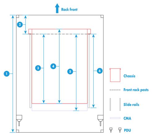
Figure 1 Installation suggestions for a 1200 mm deep rack (top view)
|
(1) 1200 mm (47.24 in) rack depth |
|
(2) A minimum of 50 mm (1.97 in) between the front rack posts and the front rack door |
|
(3) 780 mm (30.71 in) between the front rack posts and the rear of the chassis, including power supply handles at the server rear (not shown in the figure) |
|
(4) 800 mm (31.50 in) server depth, including chassis ears |
|
(5) 960 mm (37.80 in) between the front rack posts and the CMA |
|
(6) 860 mm (33.86 in) between the front rack posts and the rear ends of the slide rails |
Installation site requirements
Space and airflow requirements
For convenient maintenance and heat dissipation, make sure the following requirements are met:
· A minimum clearance of 635 mm (25 in) is reserved in front of the rack.
· A minimum clearance of 762 mm (30 in) is reserved behind the rack.
· A minimum clearance of 1219 mm (47.99 in) is reserved between racks.
· A minimum clearance of 2 mm (0.08 in) is reserved between the server and its adjacent units in the same rack.
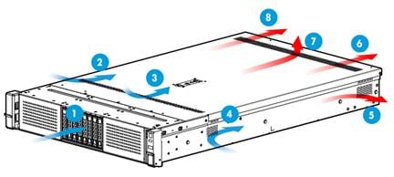
Figure 2 Airflow through the server
|
(1) to (4) Directions of the airflow into the chassis and power supplies |
|
(5) to (7) Directions of the airflow out of the chassis |
|
(8) Direction of the airflow out of the power supplies |
Temperature and humidity requirements
To ensure correct operation of the server, make sure the room temperature and humidity meet the requirements as described in "Appendix A Server specifications."
Equipment room height requirements
To ensure correct operation of the server, make sure the equipment room height meets the requirements as described in "Appendix A Server specifications."
Cleanliness requirements
Mechanically active substances buildup on the chassis might result in electrostatic adsorption, which causes poor contact of metal components and contact points. In the worst case, electrostatic adsorption can cause communication failure.
Table 3 Mechanically active substance concentration limit in the equipment room
|
Substance |
Particle diameter |
Concentration limit |
|
Dust particles |
≥ 5 µm |
≤ 3 x 10⁴ particles/m3 (No visible dust on desk in three days) |
|
Dust (suspension) |
≤ 75 µm |
≤ 0.2 mg/m3 |
|
Dust (sedimentation) |
75 µm to 150 µm |
≤ 1.5 mg/(m2h) |
|
Sand |
≥ 150 µm |
≤ 30 mg/m3 |
The equipment room must also meet limits on salts, acids, and sulfides to eliminate corrosion and premature aging of components, as shown in Table 4.
Table 4 Harmful gas limits in an equipment room
|
Gas |
Maximum concentration (mg/m3) |
|
SO2 |
0.2 |
|
H2S |
0.006 |
|
NO2 |
0.04 |
|
NH3 |
0.05 |
|
Cl2 |
0.01 |
Grounding requirements
Correctly connecting the server grounding cable is crucial to lightning protection, anti-interference, and ESD prevention. The server can be grounded through the grounding wire of the power supply system and no external grounding cable is required.
Installation tools
Table 5 lists the tools that you might use during installation.
|
Picture |
Name |
Description |
|
|
T25 Torx screwdriver |
For captive screws inside chassis ears. |
|
T30 Torx screwdriver |
For captive screws on processor heatsinks. |
|
|
T15 Torx screwdriver (shipped with the server) |
For screws on access panels. |
|
|
T10 Torx screwdriver (shipped with the server) |
For screws on PCIe module blanks or riser card blanks. |
|
|
Flat-head screwdriver |
For captive screws inside chassis ears or for replacing system batteries. |
|
|
Phillips screwdriver |
For screws on SATA M.2 SSDs. |
|
|
|
Cage nut insertion/extraction tool |
For insertion and extraction of cage nuts in rack posts. |
|
|
Diagonal pliers |
For clipping insulating sleeves. |
|
|
Tape measure |
For distance measurement. |
|
|
Multimeter |
For resistance and voltage measurement. |
|
|
ESD wrist strap |
For ESD prevention when you operate the server. |
|
|
Antistatic gloves |
For ESD prevention when you operate the server. |
|
|
Antistatic clothing |
For ESD prevention when you operate the server. |
|
|
Ladder |
For high-place operations. |
|
|
Interface cable (such as an Ethernet cable or optical fiber) |
For connecting the server to an external network. |
|
|
Monitor (such as a PC) |
For displaying the output from the server. |


Installing or removing the server
Installing the server
As a best practice, install hardware options on the server (if needed) before installing the server in the rack. For more information about how to install hardware options, see "Installing hardware options."
Installing rails
Install the inner rails and the middle-outer rails in the rack mounting rail kit on the server and the rack, respectively. For information about installing the rails, see the document shipped with the rails.
Rack-mounting the server
|
|
WARNING! To avoid bodily injury, slide the server into the rack with caution for the sliding rails might squeeze your fingers. |
To rack-mount the server:
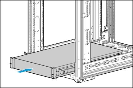
1. Slide the server into the rack. For more information about how to slide the server into the rack, see the document shipped with the rails.
Figure 3 Rack-mounting the server
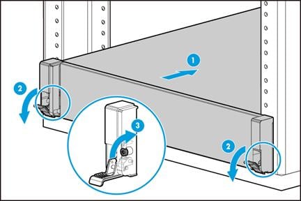
2. Secure the server:
a. Push the server until the chassis ears are flush against the rack front posts, as shown by callout 1 in Figure 4.
b. Unlock the latches of the chassis ears, as shown by callout 2 in Figure 4.
c. Fasten the captive screws inside the chassis ears and lock the latches, as shown by callout 3 in Figure 4.
(Optional) Installing cable management brackets
Install cable management brackets if the server is shipped with cable management brackets. For information about how to install cable management brackets, see the installation guide shipped with the brackets.
Connecting external cables
Cabling guidelines
|
|
WARNING! To avoid electric shock, fire, or damage to the equipment, do not connect communication equipment to RJ-45 Ethernet ports on the server. |
· For heat dissipation, make sure no cables block the inlet or outlet air vents of the server.
· To easily identify ports and connect/disconnect cables, make sure the cables do not cross.
· Label the cables for easy identification of the cables.
· Wrap unused cables onto an appropriate position on the rack.
· To avoid damage to cables when extending the server out of the rack, do not route the cables too tight if you use cable management brackets.
Connecting a mouse, keyboard, and monitor
About this task
The server provides a maximum of two VGA connectors for connecting a monitor.
· One on the rear panel.
· One on the front panel if an installed chassis ear contains a VGA connector and a USB 2.0 port.
The server is not shipped with a standard PS2 mouse and keyboard. To connect a PS2 mouse and keyboard, you must prepare a USB-to-PS2 adapter.
Procedure
1. Connect one plug of a VGA cable to a VGA connector on the server, and fasten the screws on the plug.
Figure 5 Connecting a VGA cable
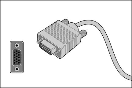
2. Connect the other plug of the VGA cable to the VGA connector on the monitor, and fasten the screws on the plug.
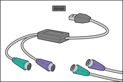
3. Connect the mouse and keyboard.
¡ For a USB mouse and keyboard, directly connect the USB connectors of the mouse and keyboard to the USB connectors on the server.
¡ For a PS2 mouse and keyboard, insert the USB connector of the USB-to-PS2 adapter to a USB connector on the server. Then, insert the PS2 connectors of the mouse and keyboard into the PS2 receptacles of the adapter.
Figure 6 Connecting a PS2 mouse and keyboard by using a USB-to-PS2 adapter
Connecting an Ethernet cable
About this task
Perform this task before you set up a network environment or log in to the HDM management interface through the HDM network port to manage the server.
Procedure
1. Determine the network port on the server.
¡ To connect the server to the external network, use the Ethernet port on the Ethernet adapter.
¡ To log in to the HDM management interface, use the HDM network port on the server. For the position of the HDM network port, see "Rear panel view."
2. Determine the type of the Ethernet cable.
Verify the connectivity of the cable by using a link tester.
If you are replacing the Ethernet cable, make sure the new cable is of the same type with the old cable or compatible with the old cable.
3. Label the Ethernet cable by filling in the names and numbers of the server and the peer device on the label.
As a best practice, use labels of the same kind for all cables.
If you are replacing the Ethernet cable, label the new cable with the same number as the number of the old cable.
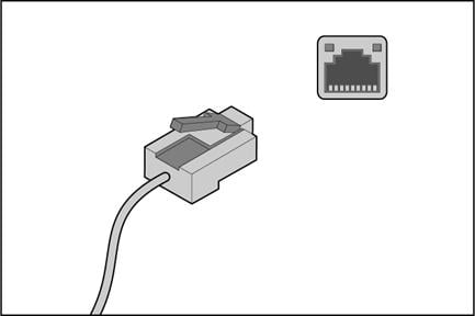
4. Connect one end of the Ethernet cable to the network port on the server and the other end to the peer device.
Figure 7 Connecting an Ethernet cable
5. Verify network connectivity.
After powering on the server, use the ping command to test the network connectivity. If the connection between the server and the peer device fails, make sure the Ethernet cable is correctly connected.
6. Secure the Ethernet cable. For information about how to secure cables, see "Securing cables."
Connecting a USB device
About this task
Perform this task before you install the operating system of the server or transmit data through a USB device.
The server provides a maximum of six USB connectors.
· One USB 2.0 connector and one USB 3.0 connector on the front panel if an installed chassis ear contains a VGA connector, a USB 2.0 connector, and a USB 3.0 connector.
· Two USB 3.0 connectors on the rear panel.
· Two internal USB 2.0 connector for connecting USB devices that are not designed to be installed and removed very often.
Guidelines
Before connecting a USB device, make sure the USB device can operate correctly and then copy data to the USB device.
USB devices are hot swappable.
As a best practice for compatibility, purchase officially certified USB devices.
Procedure
1. (Optional.) Remove the access panel if you need to connect the USB device to an internal USB connector. For information about how to remove the access panel, see "Replacing the access panel."
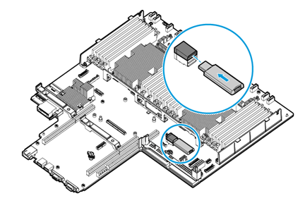
2. Connect the USB device to the USB connector, as shown in Figure 8.
Figure 8 Connecting a USB device to an internal USB connector
3. (Optional.) Install the access panel. For information about how to install the access panel, see "Replacing the access panel."
4. Verify that the server can identify the USB device.
If the server fails to identify the USB device, download and install the driver of the USB device. If the server still fails to identify the USB device after the driver is installed, replace the USB device.
Connecting the power cord
Guidelines
|
|
WARNING! To avoid damage to the equipment or even bodily injury, use the power cord that ships with the server. |
Before connecting the power cord, make sure the server and components are installed correctly.
Connecting the AC power cord for an AC or 240 V high-voltage DC power supply
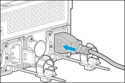
1. Insert the power cord plug into the power receptacle of a power supply at the rear panel, as shown in Figure 9.
Figure 9 Connecting the AC power cord
2. Connect the other end of the power cord to the power source, for example, the power strip on the rack.
3. Secure the power cord to avoid unexpected disconnection of the power cord.
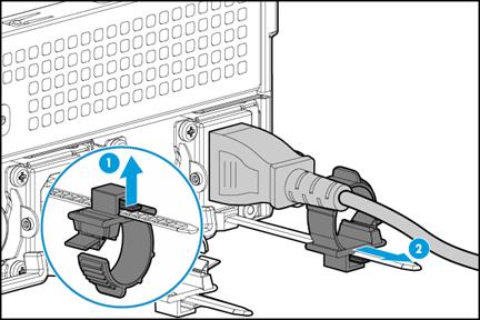
a. (Optional.) If the cable clamp is positioned too near the power cord that it blocks the power cord plug connection, press down the tab on the cable mount and slide the clip backward.
Figure 10 Sliding the cable clamp backward
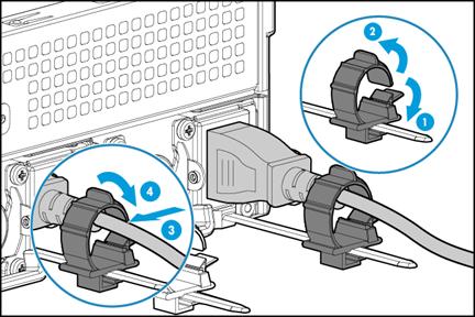
b. Open the cable clamp, place the power cord through the opening in the cable clamp, and then close the cable clamp, as shown by callouts 1, 2, 3, and 4 in Figure 11.
Figure 11 Securing the AC power cord
c. Slide the cable clamp forward until it is flush against the edge of the power cord plug, as shown in Figure 12.
Figure 12 Sliding the cable clamp forward
Connecting the DC power cord for a –48 VDC power supply
|
|
WARNING! Provide a circuit breaker for each power cord. Make sure the circuit breaker is switched off before you connect a DC power cord. |
To connect the DC power cord for a –48 VDC power supply:
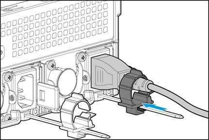
1. Connect the power cord plug to the power receptacle of a –48 VDC power supply at the rear panel, as shown in Figure 13.
Figure 13 Connecting the DC power cord

2. Fasten the screws on the power cord plug to secure it into place, as shown in Figure 14.
Figure 14 Securing the DC power cord

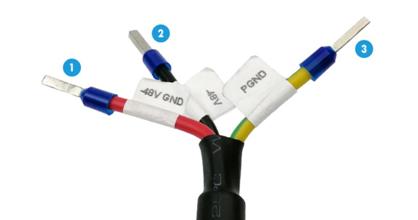
3. Connect the other end of the power cord to the power source, as shown in Figure 15.
The DC power cord contains three wires: –48V GND, –48V, and PGND. Connect the three wires to the corresponding terminals of the power source. The wire tags in the figure are for illustration only.
Figure 15 Three wires at the other end of the DC power cord
Securing cables
Securing cables to cable management brackets
For information about how to secure cables to cable management brackets, see the installation guide shipped with the brackets.
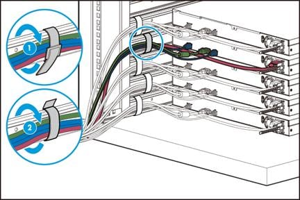
Securing cables to slide rails by using cable straps
You can secure cables to either left slide rails or right slide rails. As a best practice for cable management, secure cables to left slide rails.
When multiple cable straps are used in the same rack, stagger the strap location, so that the straps are adjacent to each other when viewed from top to bottom. This positioning will enable the slide rails to slide easily in and out of the rack.
To secure cables to slide rails by using cable straps:
1. Hold the cables against a slide rail.
2. Wrap the strap around the slide rail and loop the end of the cable strap through the buckle.
3. Dress the cable strap to ensure that the extra length and buckle part of the strap are facing outside of the slide rail.
Figure 16 Securing cables to a slide rail
Removing the server from a rack
1. Power down the server. For more information, see "Powering off the server."
2. Disconnect all peripheral cables from the server.
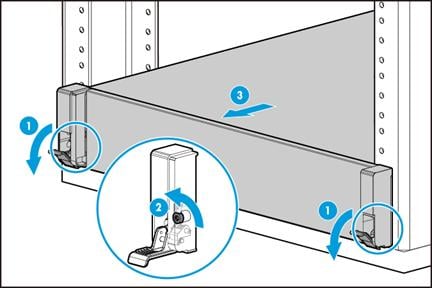
3. Extend the server from the rack, as shown in Figure 17.
a. Open the latches of the chassis ears.
b. Loosen the captive screws.
c. Slide the server out of the rack.
Figure 17 Extending the server from the rack
4. Place the server on a clean, stable surface.
Powering on and powering off the server
Important information
If the server is connected to external storage devices, make sure the server is the first device to power off and then the last device to power on. This restriction prevents the server from mistakenly identifying the external storage devices as faulty devices.
Powering on the server
Prerequisites
Before you power on the server, you must complete the following tasks:
· Install the server and internal components correctly.
· Connect the server to a power source.
Procedure
Powering on the server by pressing the power on/standby button
Press the power on/standby button to power on the server.
The server exits standby mode and supplies power to the system. The system power LED changes from steady amber to flashing green and then to steady green. For information about the position of the system power LED, see "LEDs and buttons."
Powering on the server from the HDM Web interface
1. Log in to the HDM.
For information about how to log in to HDM, see the firmware update guide for the server.
2. Power on the server.
For more information, see HDM online help.
Powering on the server from the remote console interface
1. Log in to HDM.
For information about how to log in to HDM, see the firmware update guide for the server.
2. Log in to a remote console and then power on the server.
For information about how to log in to a remote console, see HDM online help.
Configuring automatic power-on
You can configure automatic power-on from HDM or BIOS.
To configure automatic power-on from HDM:
1. Log in to HDM.
For information about how to log in to HDM, see the firmware update guide for the server.
2. Enable automatic power-on.
For more information, see HDM online help.
To configure automatic power-on from the BIOS, set AC Restore Settings to Always Power On. For more information, see the BIOS user guide for the server.
Powering off the server
Prerequisites
Before powering off the server, you must complete the following tasks:
· Install the server and internal components correctly.
· Backup all critical data.
· Make sure all services have stopped or have been migrated to other servers.
Procedure
Powering off the server from its operating system
1. Connect a monitor, mouse, and keyboard to the server.
2. Shut down the operating system of the server.
3. Disconnect all power cords from the server.
Powering off the server by pressing the power on/standby button
1. Press the power on/standby button and wait for the system power LED to turn into steady amber.
2. Disconnect all power cords from the server.
Powering off the server forcedly by pressing the power on/standby button
|
|
IMPORTANT: This method forces the server to enter standby mode without properly exiting applications and the operating system. Use this method only when the server system crashes. For example, a process gets stuck. |
1. Press and hold the power on/standby button until the system power LED turns into steady amber.
2. Disconnect all power cords from the server.
Powering off the server from the HDM Web interface
1. Log in to HDM.
For information about how to log in to HDM, see the firmware update guide for the server.
2. Power off the server.
For more information, see HDM online help.
3. Disconnect all power cords from the server.
Powering off the server from the remote console interface
1. Log in to HDM.
For information about how to log in to HDM, see the firmware update guide for the server.
2. Log in to a remote console and then power off the server.
For information about how to log in to a remote console, see HDM online help.
3. Disconnect all power cords from the server.
Configuring the server
The following information describes the procedures to configure the server after the server installation is complete.
Powering on the server
1. Power on the server. For information about the procedures, see "Powering on the server."
2. Verify that the health LED on the front panel is steady green, which indicates that the system is operating correctly. For more information about the health LED status, see "LEDs and buttons."
Updating firmware
|
|
IMPORTANT: Verify the hardware and software compatibility before firmware upgrade. For information about the hardware and software compatibility, see the software release notes. |
You can update the following firmware from FIST or HDM:
· HDM.
· BIOS.
· CPLD.
For information about the update procedures, see the firmware update guide for the server
Deploying and registering UIS Manager
For information about deploying UIS Manager, see H3C UIS Manager Installation Guide.
For information about registering the licenses of UIS Manager, see H3C UIS Manager 6.5 License Registration Guide.
Installing hardware options
If you are installing multiple hardware options, read their installation procedures and identify similar steps to streamline the entire installation procedure.
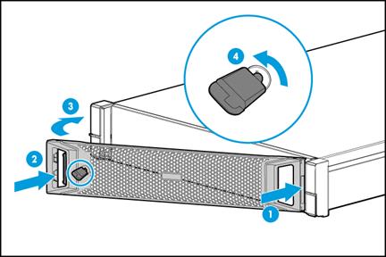
Installing the security bezel
1. Press the right edge of the security bezel into the groove in the right chassis ear on the server, as shown by callout 1 in Figure 18.
2. Press the latch at the other end, close the security bezel, and then release the latch to secure the security bezel into place. See callouts 2 and 3 in Figure 18.
3. Insert the key provided with the bezel into the lock on the bezel and lock the security bezel, as shown by callout 4 in Figure 18. Then, pull out the key and keep it safe.
|
|
CAUTION: To avoid damage to the lock, hold down the key while you are turning the key. |
Figure 18 Installing the security bezel
Installing SAS/SATA drives
Guidelines
The drives are hot swappable. If you hot swap an HDD repeatedly within 30 seconds, the system might fail to identify the drive.
If you are using the drives to create a RAID, follow these restrictions and guidelines:
· To build a RAID (or logical drive) successfully, make sure all drives in the RAID are the same type (HDDs or SSDs) and have the same connector type (SAS or SATA).
· For efficient use of storage, use drives that have the same capacity to build a RAID. If the drives have different capacities, the lowest capacity is used across all drives in the RAID. If one drive is used by several logical drives, RAID performance might be affected and maintenance complexities will increase.
· If the installed drive contains RAID information, you must clear the information before configuring RAIDs. For more information, see the storage controller user guide for the server.
Procedure
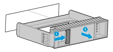
1. Remove the security bezel, if any. For more information, see "Replacing the security bezel."
2. Press the latch on the drive blank inward with one hand, and pull the drive blank out of the slot, as shown in Figure 19.
Figure 19 Removing the drive blank
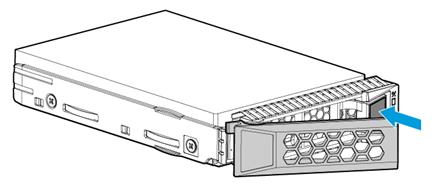
3. Install the drive:
a. Press the button on the drive panel to release the locking lever.
Figure 20 Releasing the locking lever
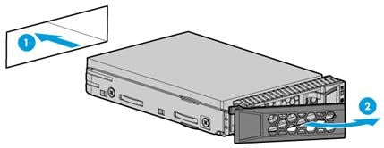
a. Insert the drive into the slot and push it gently until you cannot push it further.
b. Close the locking lever until it snaps into place.
Figure 21 Installing a drive
4. (Optional.) Install the removed security bezel. For more information, see "Installing the security bezel."
Verifying the installation
Use the following methods to verify that the drive is installed correctly:
· Verify the drive properties (including capacity) by using one of the following methods:
¡ Log in to HDM. For more information, see HDM online help.
¡ Access the BIOS. For more information, see the storage controller user guide for the server.
¡ Access the CLI or GUI of the server.
· Observe the drive LEDs to verify that the drive is operating correctly. For more information, see "Drive LEDs."
Installing NVMe drives
Guidelines
NVMe drives support hot insertion and managed hot removal.
Only one drive can be hot inserted at a time. To hot insert multiple NVMe drives, wait a minimum of 60 seconds for the previously installed NVMe drive to be identified before hot inserting another NVMe drive.
If you are using the drives to create a RAID, follow these restrictions and guidelines:
· For efficient use of storage, use drives that have the same capacity to build a RAID. If the drives have different capacities, the lowest capacity is used across all drives in the RAID. A drive with extra capacity cannot be used to build other RAIDs.
· If the installed drive contains RAID information, you must clear the information before configuring RAIDs. For more information, see the storage controller user guide for the server.
Procedure
1. Remove the security bezel, if any. For more information, see "Replacing the security bezel."
2. Push the latch on the drive blank inward, and pull the drive blank out of the slot, as shown in Figure 22.
Figure 22 Removing the drive blank
3. Install the drive:
a. Press the button on the drive panel to release the locking lever.
Figure 23 Releasing the locking lever

b. Insert the drive into the bay and push it gently until you cannot push it further.
c. Close the locking lever until it snaps into place.
Figure 24 Installing a drive
4. (Optional.) Install the security bezel. For more information, see "Installing the security bezel."
Verifying the installation
Use the following methods to verify that the drive is installed correctly:
· Verify the drive properties (including capacity) by using one of the following methods:
¡ Access HDM. For more information, see HDM online help.
¡ Access the BIOS. For more information, see the BIOS user guide for the server.
¡ Access the CLI or GUI of the server.
· Observe the drive LEDs to verify that the drive is operating correctly. For more information, see "Drive LEDs."
Installing power supplies
Guidelines
· The power supplies are hot swappable.
· Make sure the installed power supplies are the same model. HDM will perform power supply consistency check and generate an alarm if the power supply models are different.
· To avoid hardware damage, do not use third-party power supplies.
Procedure
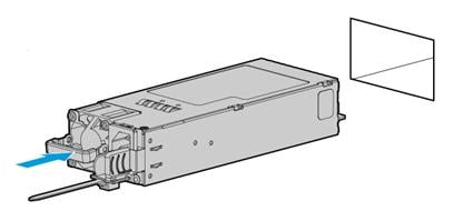
1. As shown in Figure 25, remove the power supply blank from the target power supply slot.
Figure 25 Removing the power supply blank
2. Align the power supply with the slot, making sure its fan is on the left.
3. Push the power supply into the slot until it snaps into place.
Figure 26 Installing a power supply
4. Connect the power cord. For more information, see "Connecting the power cord."
Verifying the installation
Use one of the following methods to verify that the power supply is installed correctly:
· Observe the power supply LED to verify that the power supply is operating correctly. For more information about the power supply LED, see LEDs in "Rear panel."
· Log in to HDM to verify that the power supply is operating correctly. For more information, see HDM online help.
Installing riser cards and PCIe modules
The server provides three PCIe riser connectors on the system board to connect riser cards, which hold PCIe modules. For more information about the connector locations, see "System board components."
Guidelines
· You can install a PCIe module in a PCIe slot for a larger-sized PCIe module. For example, an LP PCIe module can be installed in a slot for an FHFL PCIe module.
· A PCIe slot can supply power to the installed PCIe module if the maximum power consumption of the module does not exceed 75 W. If the maximum power consumption exceeds 75 W, a power cord is required. The following GPU modules require a power cord:
¡ GPU-M4000-1-X.
¡ GPU-K80-1.
¡ GPU-M60-1-X.
¡ GPU-P40-X.
¡ GPU-M10-X.
¡ GPU-P100.
¡ GPU-V100-32G.
¡ GPU-V100.
For more information about connecting the power cord, see "Connecting the power cord of a GPU module."
· For more information about PCIe module and riser card compatibility, see "Riser cards."
· The installation procedure and requirements vary by riser card model. Use Table 6 to identify the installation procedure, requirements, and applicable PCIe riser connectors for each riser card.
Table 6 Riser card installation location
|
Riser card model |
PCIe riser connectors |
Installation procedure |
|
RC-3GPU-R4900-G3 RC-FHHL-2U-G3-1 RS-3*FHHL-R4900 |
1 and 2 |
Installing an RC-3GPU-R4900-G3, RC-FHHL-2U-G3-1, or RS-3*FHHL-R4900 riser card and a PCIe module |
|
RC-GPU/FHHL-2U-G3-1 |
1 and 2 |
Installing an RC-GPU/FHHL-2U-G3-1 riser card and a PCIe module |
|
RC-2*FHFL-2U-G3 |
1 |
Installing an RC-2*FHFL-2U-G3 riser card and a PCIe module NOTE: A RC-Mezz-Riser-G3 Mezz PCIe riser card is required. |
|
RC-FHHL-2U-G3-2 |
Installing an RC-FHHL-2U-G3-2 riser card and a PCIe module A riser card bracket is required. |
|
|
RC-2*LP-2U-G3 |
3 |
Installing an RC-2*LP-2U-G3 riser card and a PCIe module A riser card bracket is required. |
|
RC-2GPU-R4900-G3 RC-GPU/FHHL-2U-G3-2 |
3 |
Installing an RC-GPU/FHHL-2U-G3-2 or RC-2GPU-R4900-G3 riser card and a PCIe module NOTE: A riser card bracket is required. |
Installing an RC-3GPU-R4900-G3, RC-FHHL-2U-G3-1, or RS-3*FHHL-R4900 riser card and a PCIe module
The installation procedure is the same for the RC-3GPU-R4900-G3, RC-FHHL-2U-G3-1, and RS-3*FHHL-R4900. This section installs the RS-3*FHHL-R4900.
To install an RS-3*FHHL-R4900 riser card and a PCIe module:
1. Power off the server. For more information, see "Powering off the server."
2. Remove the server from the rack. For more information, see "Removing the server from a rack."
3. Remove the access panel. For more information, see "Replacing the access panel."
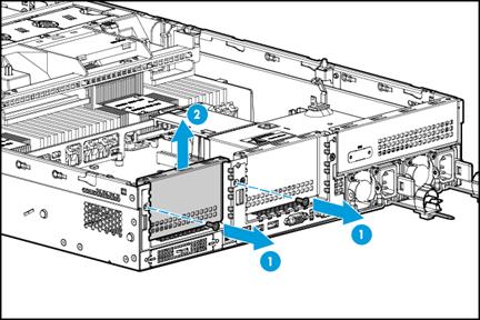
4. Remove the screws from the riser card blank in PCIe riser connector 1 or 2, and then lift the blank to remove it from the connector, as shown in Figure 27. This example uses PCIe riser connector 1 to show the installation procedure.
Figure 27 Removing the riser card blank

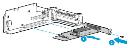
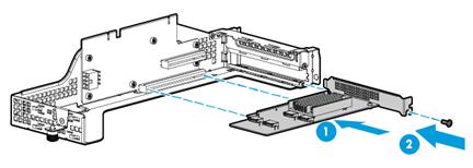
5. Install the PCIe module to the riser card:
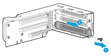
a. Remove the screw on the PCIe module blank in the target PCIe slot, and then pull the blank out of the slot, as shown in Figure 28.
Figure 28 Removing the PCIe module blank
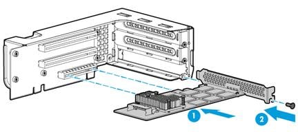
b. Insert the PCIe module into the slot along the guide rails and use the screw to secure it into place, as shown in Figure 29.
Figure 29 Installing the PCIe module
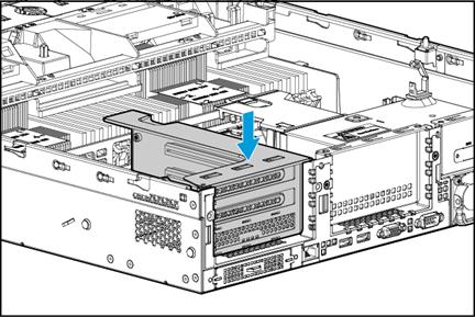
6. Insert the riser card in the PCIe riser connector, as shown in Figure 30.
Figure 30 Installing the riser card
7. Connect PCIe module cables, if any.
8. Install the access panel. For more information, see "Replacing the access panel."
9. Rack-mount the server. For more information, see "Rack-mounting the server."
10. Connect the power cord. For more information, see "Connecting the power cord."
11. Power on the server. For more information, see "Powering on the server."
Installing an RC-GPU/FHHL-2U-G3-1 riser card and a PCIe module
1. Power off the server. For more information, see "Powering off the server."
2. Remove the server from the rack. For more information, see "Removing the server from a rack."
3. Remove the access panel. For more information, see "Replacing the access panel."
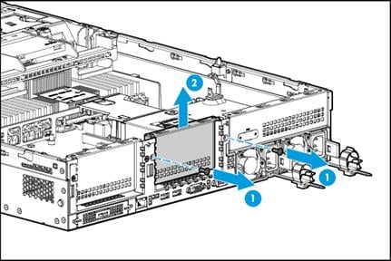
4. Remove the screws from the riser card blank in PCIe riser connector 1 or 2, and then lift the blank until it is unseated from the connector, as shown in Figure 31. This example uses PCIe riser connector 2 to show the installation procedure.
Figure 31 Removing the riser card blank
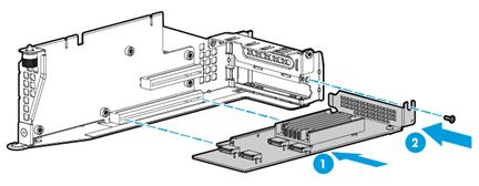
5. Install the PCIe module to the riser card:
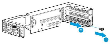
a. Remove the screw on the PCIe module blank in the target PCIe slot, and then pull the blank out of the slot, as shown in Figure 32.
Figure 32 Removing the PCIe module blank
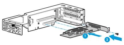
b. Insert the PCIe module into the slot along the guide rails and use the screw to secure it into place, as shown in Figure 33.
Figure 33 Installing the PCIe module
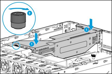
6. Insert the riser card in PCIe riser connector 2, and then fasten the captive screw to the chassis air baffle, as shown in Figure 34.
Figure 34 Installing the riser card
7. Connect PCIe module cables, if any.
8. Install the access panel. For more information, see "Replacing the access panel."
9. Rack-mount the server. For more information, see "Rack-mounting the server."
10. Connect the power cord. For more information, see "Connecting the power cord."
11. Power on the server. For more information, see "Powering on the server."
Installing an RC-2*FHFL-2U-G3 riser card and a PCIe module
The RC-2*FHFL-2U-G3 riser card can only be installed on PCIe riser connector 1.
To install an RC-2*FHFL-2U-G3 riser card and a PCIe module:
1. Power off the server. For more information, see "Powering off the server."
2. Remove the server from the rack. For more information, see "Removing the server from a rack."
3. Remove the access panel. For more information, see "Replacing the access panel."
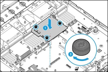
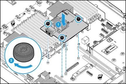
4. Install an RC-Mezz-Riser-G3 Mezz PCIe riser card. As shown in Figure 35, place the module onto the system board, with the pin holes on the module aligned with the guide pins on the system board. Then, fasten the captive screws on the module to secure it into place.
Figure 35 Installing an RC-Mezz-Riser-G3 Mezz PCIe riser card
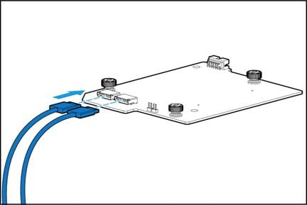
5. Connect two PCIe signal cables to the RC-Mezz-Riser-G3 Mezz PCIe riser card, as shown in Figure 36.
Figure 36 Connecting PCIe signal cables to the RC-Mezz-Riser-G3 Mezz PCIe riser card
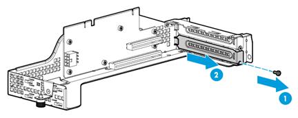
6. Lift the riser card blank to remove it from PCIe riser connector 1, as shown in Figure 37.
Figure 37 Removing the riser card blank from PCIe riser connector 1
7. Install the PCIe module to the riser card:
a. Remove the screw on the PCIe module blank in the target PCIe slot, and then pull the blank out of the slot, as shown in Figure 38.
Figure 38 Removing the PCIe module blank

b. Insert the PCIe module into the slot along the guide rails and use the screw to secure it into place, as shown in Figure 39.
Figure 39 Installing the PCIe module
8. Connect the other end of the PCIe signal cables to the riser card, as shown in Figure 40.
|
|
NOTE: For simplicity, the figure does not show the PCIe module attached to the riser card. |
Figure 40 Connecting PCIe signal cables to the riser card
9. Install the riser card on PCIe riser connector 1. For more information, see "Installing an RC-GPU/FHHL-2U-G3-1 riser card and a PCIe module."
10. Connect PCIe module cables, if any.
11. Install the access panel. For more information, see "Replacing the access panel."
12. Rack-mount the server. For more information, see "Rack-mounting the server."
13. Connect the power cord. For more information, see "Connecting the power cord."
14. Power on the server. For more information, see "Powering on the server."
Installing an RC-FHHL-2U-G3-2 riser card and a PCIe module
1. Power off the server. For more information, see "Powering off the server."
2. Remove the server from the rack. For more information, see "Removing the server from a rack."
3. Remove the access panel. For more information, see "Replacing the access panel."
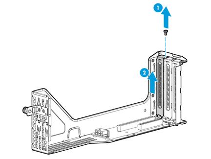
4. Lift the riser card blank to remove it from PCIe riser connector 3, as shown in Figure 41.
Figure 41 Removing the riser card blank
5. Install the PCIe module to the riser card:
a. Remove the screw on the PCIe module blank in the target PCIe slot, and then pull the blank out of the slot, as shown in Figure 42.
Figure 42 Removing the PCIe module blank
b. Insert the PCIe module into the slot along the guide rails and use the screw to secure it into place, as shown in Figure 43.
Figure 43 Installing the PCIe module
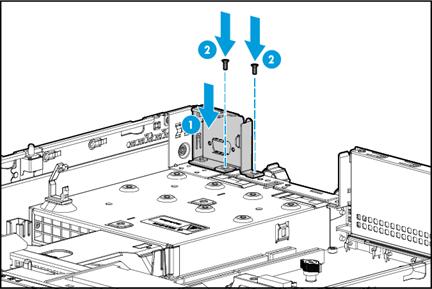
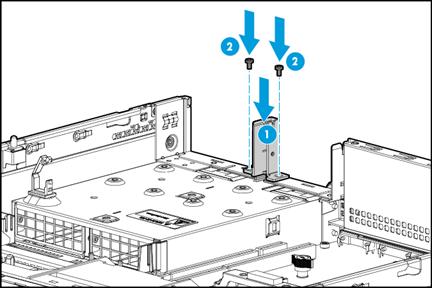
6. Install the riser card bracket and use screws to secure it into place, as shown in Figure 44.
Figure 44 Installing the riser card bracket
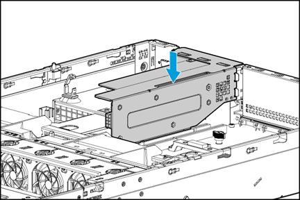
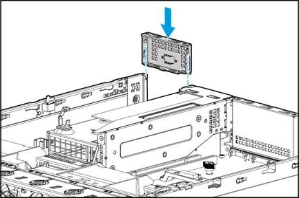
7. Insert the riser card in PCIe riser connector 3, as shown in Figure 45.
Figure 45 Installing the riser card
8. Connect PCIe module cables, if any.
9. Install the access panel. For more information, see "Replacing the access panel."
10. Rack-mount the server. For more information, see "Rack-mounting the server."
11. Connect the power cord. For more information, see "Connecting the power cord."
12. Power on the server. For more information, see "Powering on the server."
Installing an RC-2*LP-2U-G3 riser card and a PCIe module
1. Power off the server. For more information, see "Powering off the server."
2. Remove the server from the rack. For more information, see "Removing the server from a rack."
3. Remove the access panel. For more information, see "Replacing the access panel."
4. Remove the blank from PCIe riser connector 3, as shown in Figure 41.
5. Remove the power supply air baffle. For more information, see "Removing air baffles."
6. Install the PCIe module to the riser card:
a. Remove the screw on the PCIe module blank in the target PCIe slot, and then pull the blank out of the slot, as shown in Figure 46.
Figure 46 Removing the PCIe module blank

b. Insert the PCIe module into the slot along the guide rails and use the screw to secure it into place, as shown in Figure 47.
Figure 47 Installing the PCIe module
7. Install the riser card bracket and use screws to secure it into place, as shown in Figure 48.
Figure 48 Installing the riser card bracket
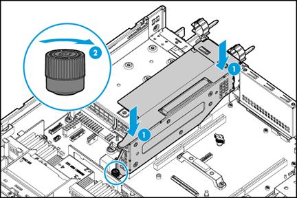
8. Insert the riser card in PCIe riser connector 3 and fasten the captive screw to the system board, as shown in Figure 49.
Figure 49 Installing the riser card
9. Install the PCIe riser card blank, as shown in Figure 50.
Figure 50 Installing the PCIe riser card blank
10. Install the power supply air baffle. For more information, see "Installing air baffles."
11. Connect PCIe module cables, if any.
12. Install the access panel. For more information, see "Replacing the access panel."
13. Rack-mount the server. For more information, see "Rack-mounting the server."
14. Connect the power cord. For more information, see "Connecting the power cord."
15. Power on the server. For more information, see "Powering on the server."
Installing an RC-GPU/FHHL-2U-G3-2 or RC-2GPU-R4900-G3 riser card and a PCIe module
The installation procedure is the same for the RC-GPU/FHHL-2U-G3-2 and RC-2GPU-R4900-G3. This section installs the RC-GPU/FHHL-2U-G3-2.
To install an RC-GPU/FHHL-2U-G3-2:
1. Power off the server. For more information, see "Powering off the server."
2. Remove the server from the rack. For more information, see "Removing the server from a rack."
3. Remove the access panel. For more information, see "Replacing the access panel."
4. Remove the PCIe riser card blank from PCIe riser connector 3, as shown in Figure 41.
5. Install the PCIe module to the riser card:
a. Remove the screw on the PCIe module blank in the target PCIe slot, and then pull the blank out of the slot, as shown in Figure 51.
Figure 51 Removing the PCIe module blank
b. Insert the PCIe module into the slot along the guide rails and use the screw to secure it into place, as shown in Figure 52.
Figure 52 Installing the PCIe module
6. Install the riser card bracket and use its screws to secure it into place, as shown in Figure 44.
7. Insert the riser card in PCIe riser connector 3 and fasten the captive screw to the chassis air baffle, as shown in Figure 53.
Figure 53 Installing the riser card
8. Connect PCIe module cables, if any.
9. Install the access panel. For more information, see "Replacing the access panel."
10. Rack-mount the server. For more information, see "Rack-mounting the server."
11. Connect the power cord. For more information, see "Connecting the power cord."
12. Power on the server. For more information, see "Powering on the server."
Installing storage controllers and power fail safeguard modules
For some storage controllers, you can order a power fail safeguard module to prevent data loss when power outage occurs.
A power fail safeguard module provides a flash card and a supercapacitor. When a system power failure occurs, this supercapacitor can provide power for a minimum of 20 seconds. During this interval, the storage controller transfers data from DDR memory to the flash card, where the data remains indefinitely or until the controller retrieves the data.
Guidelines
To install multiple storage controllers, make sure they are from the same vendor. For the storage controllers available for the server and their vendors, use the component query tool for the server at the H3C official website.
Make sure the power fail safeguard module is compatible with the storage controller. For the compatibility matrix, see "Storage controllers."
The supercapacitor might have a low charge after the power fail safeguard module is installed or after the server is powered up. If the system displays that the supercapacitor has low charge, no action is required. The system will charge the supercapacitor automatically. You can view the status of the supercapacitor from the BIOS.
Each supercapacitor has a short supercapacitor cable attached to it and requires an extension cable for storage controller connection. The required extension cable varies by supercapacitor model and storage controller model. Use Table 7 to determine the extension cable to use.
Table 7 Supercapacitor extension cable selection
|
Storage controller type |
Storage controller model |
Supercapacitor |
Extension cable P/N |
|
Mezzanine |
· RAID-P430-M1 · RAID-P430-M2 |
Supercapacitor of the Flash-PMC-G2 power fail safeguard module |
N/A This cable does not have a P/N. |
|
RAID-P460-M2 |
BAT-PMC-G3 |
0404A0TG |
|
|
RAID-P460-M4 |
BAT-PMC-G3 |
0404A0TG |
|
|
RAID-L460-M4 |
BAT-LSI-G3 |
0404A0XH |
|
|
Standard |
· RAID-LSI-9361-8i(1G)-A1-X · RAID-LSI-9361-8i(2G)-1-X |
Supercapacitor of the Flash-LSI-G2 power fail safeguard module |
0404A0SV |
|
· RAID-LSI-9460-8i(2G) · RAID-LSI-9460-8i(4G) · RAID-LSI-9460-16i(4G) |
BAT-LSI-G3 |
0404A0VC |
|
|
RAID-P460-B2 |
BAT-PMC-G3 |
0404A0TG |
|
|
RAID-P460-B4 |
BAT-PMC-G3 |
0404A0TG |
|
|
IMPORTANT: A supercapacitor has a lifespan of 3 to 5 years. The power fail safeguard module fails when the supercapacitor expires. Replace the supercapacitor immediately upon its expiration. The system outputs an SDS log and displays the flash card status as follows when a supercapacitor expires. For more information, see HDM online help. · For a PMC storage controller, the flash card status is Abnormal_status co. You can identify the reasons that cause the supercapacitor anomaly based on the status code. · For an LSI storage controller, the flash card status is Abnormal. |
|
|
IMPORTANT: After replacing a supercapacitor that has expired, view the logical drive cache status of the storage controller. If the logical drive cache is disabled, you must re-enable the logical disk cache related configurations to start power fail safeguard. For more information, see HDM online help. |
Installing a Mezzanine storage controller and a power fail safeguard module
Procedure
1. Power off the server. For more information, see "Powering off the server."
2. Remove the server from the rack. For more information, see "Removing the server from a rack."
3. Remove the access panel. For more information, see "Replacing the access panel."
4. Remove the air baffles as needed. For more information, see "Removing air baffles."
5. Remove the fan cage. For more information, see "Replacing the fan cage."
6. (Optional.) For the ease of installation, remove the riser cards installed on PCIe riser connectors 1 and 2, if any. For more information, see "Replacing a riser card and a PCIe module."
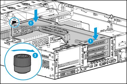
7. Align the pin holes in the Mezzanine storage controller with the guide pins on the system board. Insert the guide pins into the pin holes to place the storage controller on the system board, and then fasten the three captive screws to secure the controller, as shown in Figure 54.
Figure 54 Installing a Mezzanine storage controller
8. (Optional.) Install the flash card of the power fail safeguard module to the storage controller:
|
|
IMPORTANT: Skip this step if no power fail safeguard module is required or the storage controller has a built-in flash card. For information about storage controllers with a built-in flash card, see "Storage controllers." |
a. Install the two internal threaded studs supplied with the power fail safeguard module on the Mezzanine storage controller, as shown in Figure 55.
Figure 55 Installing the internal threaded studs
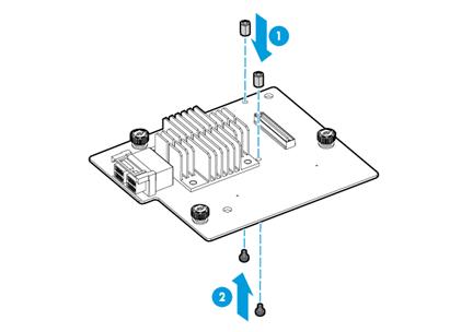
b. Slowly insert the flash card connector into the socket and use screws to secure the flash card on the storage controller, as shown in Figure 56.
Figure 56 Installing the flash card
9. (Optional.) Install the supercapacitor. For more information, see "Installing a supercapacitor."
10. (Optional.) Connect the storage controller to the supercapacitor. Connect one end of the supercapacitor extension cable to the supercapacitor cable and the other to the storage controller. For more information about the connection, see "Connecting the flash card and the supercapacitor of the power fail safeguard module."
|
|
CAUTION: Make sure the extension cable is the correct one. For more information, see Table 7. |
11. Connect drive data cables to the Mezzanine storage controller. For more information, see "Connecting drive cables."
12. Install the removed riser cards in PCIe riser connector 1 and 2. For more information, see "Installing riser cards and PCIe modules."
13. Install the removed fan cage. For more information, see "Installing fans."
14. Install the removed air baffles. For more information, see "Installing air baffles."
15. Install the access panel. For more information, see "Replacing the access panel."
16. Rack-mount the server. For more information, see "Rack-mounting the server."
17. Connect the power cord. For more information, see "Connecting the power cord."
18. Power on the server. For more information, see "Powering on the server."
Verifying the installation
Log in to HDM to verify that the Mezzanine storage controller, flash card, and supercapacitor are operating correctly. For more information, see HDM online help.
Installing a standard storage controller and a power fail safeguard module
Procedure
1. Power off the server. For more information, see "Powering off the server."
2. Remove the server from the rack. For more information, see "Removing the server from a rack."
3. Remove the access panel. For more information, see "Replacing the access panel."
4. Remove the air baffles as needed. For more information, see "Removing air baffles."
5. Remove the fan cage. For more information, see "Replacing the fan cage."
6. (Optional.) Install the flash card of the power fail safeguard module to the standard storage controller:
|
|
IMPORTANT: Skip this step if no power fail safeguard module is required or the storage controller has a built-in flash card. For information about storage controllers with a built-in flash card, see "Storage controllers." |
a. Install the two internal threaded studs supplied with the power fail safeguard module on the standard storage controller, as shown in Figure 57.
Figure 57 Installing the internal threaded studs
a. Slowly insert the flash card connector into the socket and use screws to secure the flash card on the storage controller, as shown in Figure 58.
Figure 58 Installing the flash card

7. Connect one end of the supercapacitor extension cable to the flash card.
|
|
CAUTION: Make sure the extension cable is the correct one. For more information, see Table 7. |
¡ If the storage controller is installed with an external flash card, connect the supercapacitor extension cable to the flash card.
Figure 59 Connecting the supercapacitor extension cable to the flash card
¡ If the storage controller uses a built-in flash card, connect the supercapacitor extension cable to the supercapacitor connector on the storage controller.
8. Install the standard storage controller to the server by using a riser card. For more information, see "Installing riser cards and PCIe modules."
9. (Optional.) Install the supercapacitor. For more information, see "Installing a supercapacitor."
10. (Optional.) Connect the other end of the supercapacitor extension cable to the supercapacitor. For more information about the connection, see "Connecting the flash card and the supercapacitor of the power fail safeguard module."
11. Connect the drive data cables to the standard storage controller. For more information, see "8SFF server."
12. Install the removed fan cage. For more information, see "Installing fans."
13. Install the removed air baffles. For more information, see "Installing air baffles."
14. Install the access panel. For more information, see "Replacing the access panel."
15. Rack-mount the server. For more information, see "Rack-mounting the server."
16. Connect the power cord. For more information, see "Connecting the power cord."
17. Power on the server. For more information, see "Powering on the server."
Verifying the installation
Log in to HDM to verify that the standard storage controller, flash card, and supercapacitor are operating correctly. For more information, see HDM online help.
Installing a supercapacitor
Guidelines
You can install a supercapacitor in the server chassis, on the air baffle, or in a supercapacitor container. The priorities of these installation locations are in descending order. If the location with a high priority is unavailable, use the next available location. Table 8 shows the supercapacitors that can be deployed at each location.
Table 8 Supercapacitors available for each installation location
|
Installation location |
Available supercapacitors |
Remarks |
|
In the server chassis |
· Supercapacitor of the Flash-PMC-G2 power fail safeguard module · Supercapacitor of the Flash-LSI-G2 power fail safeguard module · BAT-PMC-G3 · BAT-LSI-G3 |
The supercapacitor holder provided with the supercapacitor is required. For information about the location, see Figure 62. |
|
On the standard chassis air baffle |
BAT-PMC-G3 |
N/A |
|
In the supercapacitor container |
BAT-LSI-G3 |
Only 8SFF server supports supercapacitor containers. The location of the supercapacitor container is the same as the location of the diagnostic panel and serial label pull tab module. For more information, see "Front panel view." |
Installing a supercapacitor in the server chassis
1. Install the supercapacitor holder in the server chassis, as shown in Figure 60 and Figure 61. Make sure the bottom flanges of the supercapacitor are seated in the grooves.
Figure 60 Installing the supercapacitor holder (small-sized holder)
Figure 61 Installing the supercapacitor holder (large-sized holder)

2. Aligning the supercapacitor cable with the notch on the holder, insert the connector end of the supercapacitor into the holder. Pull the clip on the holder, insert the other end of the supercapacitor into the holder, and then release the clip, as shown in Figure 62.
Figure 62 Installing the supercapacitor
Installing the supercapacitor on the air baffle
The methods for installing a supercapacitor on the air baffle and in the server chassis are similar, except that no supercapacitor holder is required for installation on the air baffle. For more information, see "Installing a supercapacitor in the server chassis."
Installing the supercapacitor in the supercapacitor container
1. Insert the supercapacitor into the supercapacitor container and place the supercapacitor cable into the cable clamp, as shown in Figure 63.
The supercapacitor in the figure is for illustration only.
Figure 63 Inserting the supercapacitor into the supercapacitor container
2. Remove the drive, blank, serial label pull tab module, or diagnostic panel from the slot in which the supercapacitor container will be installed. After removing the drive or diagnostic panel, you must also remove the 1SFF cage.
¡ For information about removing a drive, see "Replacing a SAS/SATA drive."
¡ For information about removing a blank or serial label pull tab module, see Figure 64.
¡ For information about removing the diagnostic panel, see "Replacing the diagnostic panel."
¡ For information about removing the 1SFF cage, see Figure 65.
Figure 64 Removing a blank or serial label pull tab module
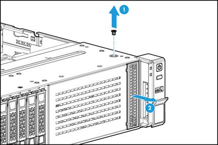
Figure 65 Removing a 1SFF cage

3. Insert the supercapacitor container into the slot, as shown in Figure 66.
Figure 66 Inserting the supercapacitor

Installing GPU modules
Guidelines
A riser card is required when you install a GPU module.
The available GPU modules and installation positions vary by riser card model and position. For more information, see "GPU module and riser card compatibility."
Use Table 9 to determine the installation method based on the GPU module model.
Table 9 GPU module installation methods
|
GPU module |
Installation requirements |
Installation method |
|
GPU-M4-1 GPU-P4-X GPU-T4 GPU-M2000 GPU-MLU100-D3 |
N/A |
Installing a GPU module without a power cord (standard chassis air baffle) |
|
GPU-M4000-1-X |
Requires a power cord (P/N 0404A0M3) and a standard chassis air baffle. |
Installing a GPU module with a power cord (standard chassis air baffle) |
|
GPU-K80-1 GPU-M60-1-X GPU-P40-X |
Requires a power cord (P/N 0404A0UC) and a standard chassis air baffle. |
|
|
GPU-M10-X |
Requires a power cord (P/N 0404A0W1) and a standard chassis air baffle. |
|
|
GPU-P100 GPU-V100 GPU-V100-32G |
Requires a power cord (P/N 0404A0UC) and a GPU-dedicated chassis air baffle |
Installing a GPU module with a power cord (GPU-dedicated chassis air baffle) |
Installing a GPU module without a power cord (standard chassis air baffle)
To install a GPU-M4-1, GPU-P4-X, GPU-T4, or GPU-MLU100-D3, make sure all the six fans are present before you power on the server.
The procedure is the same for installing a GPU module in riser cards on PCIe riser connectors 1, 2, and 3. This section uses the riser card on PCIe riser connector 1 as an example.
Procedure
1. Determine the installation position. For more information, see "GPU module and riser card compatibility."
2. Power off the server. For more information, see "Powering off the server."
3. Remove the server from the rack. For more information, see "Removing the server from a rack."
4. Remove the access panel. For more information, see "Replacing the access panel."
5. Remove the PCIe riser card blank from PCIe riser connector 1, as shown in Figure 27.
6. Attach the GPU module to the riser card.
a. Remove the screw from the target PCIe slot, and then pull the blank out of the slot, as shown in Figure 67.
Figure 67 Removing the PCIe module blank
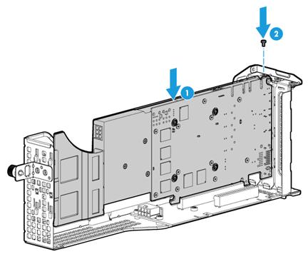
b. Insert the GPU module into PCIe slot 2 along the guide rails and fasten the screw to secure the module into place, as shown in Figure 68.
Figure 68 Installing a GPU module
7. Install the riser card on PCIe riser connector 1, and then fasten the captive screw to the chassis air baffle, as shown in Figure 69.
Figure 69 Installing the riser card

8. Connect cables for the GPU module as needed.
9. Install the access panel. For more information, see "Replacing the access panel."
10. Rack-mount the server. For more information, see "Rack-mounting the server."
11. Connect the power cord. For more information, see "Connecting the power cord."
12. Power on the server. For more information, see "Powering on the server."
Verifying the installation
Log in to HDM to verify that the GPU module is operating correctly. For more information, see HDM online help.
Installing a GPU module with a power cord (standard chassis air baffle)
To install a GPU-K80-1, GPU-M60-1-X, GPU-P40-X, or GPU-M10-X, make sure all the six fans are present before you power on the server.
The procedure is the same for installing a GPU module in riser cards on PCIe riser connectors 1, 2, and 3. This section uses the GPU-M4000-1-X and PCIe riser connector 1 as an example.
Procedure
1. Determine the installation position. For more information, see "GPU module and riser card compatibility."
2. Power off the server. For more information, see "Powering off the server."
3. Remove the server from the rack. For more information, see "Removing the server from a rack."
4. Remove the access panel. For more information, see "Replacing the access panel."
5. Remove the PCIe riser card blank from PCIe riser connector 1, as shown in Figure 27.
6. Remove the screw from the target PCIe slot, and then pull the blank out of the slot, as shown in Figure 67.
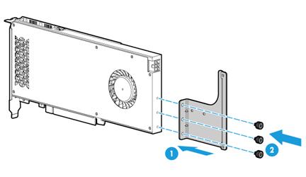
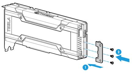
7. Attach the support bracket provided with the GPU module to the GPU module. As shown in Figure 70, align screw holes in the support bracket with the installation holes in the GPU module, and use screws to attach the support bracket to the GPU module.
Figure 70 Installing the GPU module support bracket
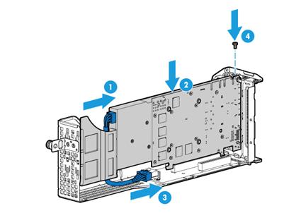
8. Install the GPU module and connect the GPU module power cord, as shown in Figure 71:
a. Connect the GPU power end of power cord to the GPU module, as shown by callout 1.
b. Insert the GPU module into PCIe slot 2 along the guide rails, as shown by callout 2.
c. Connect the other end of the power cord to the riser card and use the screw to secure the GPU module into place, as shown by callouts 3 and 4.
Figure 71 Installing a GPU module
9. Install the riser card on PCIe riser connector 1, and then fasten the captive screw to the chassis air baffle, as shown in Figure 69.
10. Connect cables for the GPU module as needed.
11. Install the access panel. For more information, see "Replacing the access panel."
12. Rack-mount the server. For more information, see "Rack-mounting the server."
13. Connect the power cord. For more information, see "Connecting the power cord."
14. Power on the server. For more information, see "Powering on the server."
Verifying the installation
Log in to HDM to verify that the GPU module is operating correctly. For more information, see HDM online help.
Installing a GPU module with a power cord (GPU-dedicated chassis air baffle)
To install a GPU-P100, GPU-V100-32G, or GPU-V100, make sure all the six fans are present before you power on the server.
The procedure is similar for installing the GPU module in riser cards on PCIe riser connectors 1, 2, and 3. This section uses the GPU-P100 and PCIe riser connector 1 as an example.
Procedure
1. Determine the installation position. For more information, see "GPU module and riser card compatibility."
2. Power off the server. For more information, see "Powering off the server."
3. Remove the server from the rack. For more information, see "Removing the server from a rack."
4. Remove the access panel. For more information, see "Replacing the access panel."
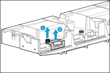
5. Remove the target support bracket from the GPU-dedicated chassis air baffle based on the PCIe riser card position.
To use PCIe riser connector 1, remove the left support bracket as shown in Figure 72. To use PCIe riser connector 2, remove the middle support bracket. To use PCIe riser connector 3, remove the right support bracket (not shown in the following figure).
Figure 72 Removing the support bracket from the GPU-dedicated chassis air baffle
6. Attach the removed support bracket to the GPU module. As shown in Figure 73, align screw holes in the support bracket with the installation holes in the GPU module, and use screws to attach the support bracket to the GPU module.
Figure 73 Installing the GPU module support bracket
7. Install the GPU module and connect the GPU module power cord. For more information, see "Installing a GPU module with a power cord (standard chassis air baffle)."
8. Remove the standard chassis air baffle and the power supply air baffle, and then install the GPU-dedicated chassis air baffle. For more information, see "Replacing air baffles."
9. Install the riser card on PCIe riser connector 1.
a. Remove the PCIe riser card blank from PCIe riser connector 1, as shown in Figure 27.
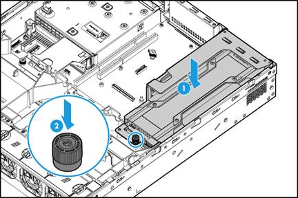
b. Align the installation hole on the GPU support bracket with the guide pin on the GPU-dedicated chassis air baffle, and place the riser card on the system board. Then, fasten the captive screw to the GPU-dedicated chassis air baffle, as shown in Figure 74.
|
|
NOTE: For simplicity, the figure does not show the GPU power cord. |
Figure 74 Installing the riser card
10. Connect cables for the GPU module as needed.
11. Install the access panel. For more information, see "Replacing the access panel."
12. Rack-mount the server. For more information, see "Rack-mounting the server."
13. Connect the power cord. For more information, see "Connecting the power cord."
14. Power on the server. For more information, see "Powering on the server."
Verifying the installation
Log in to HDM to verify that the GPU module is operating correctly. For more information, see HDM online help.
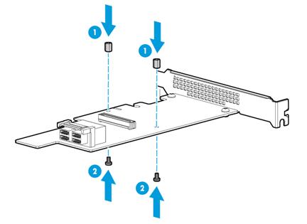
Installing Ethernet adapters
Guidelines
You can install an mLOM Ethernet adapter only in the mLOM Ethernet adapter connector on the system board. For more information about the connector location, see "System board components."
A riser card is required when you install a PCIe Ethernet adapter. For more information about PCIe Ethernet adapter and riser card compatibility, see "Riser cards."
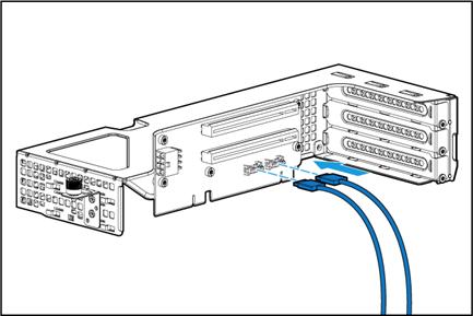
By default, port 1 on the mLOM Ethernet adapter acts as the HDM shared network port. If only a PCIe Ethernet adapter exists and the PCIe Ethernet adapter supports NCSI, port 1 on the PCIe Ethernet adapter acts as the HDM shared network port. You can configure another port on the PCIe Ethernet adapter as the HDM shared network port from the HDM Web interface. For more information, see HDM online help.
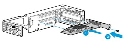
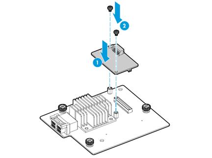
Installing an mLOM Ethernet adapter
Procedure
1. Power off the server. For more information, see "Powering off the server."
2. Install the mLOM Ethernet adapter:
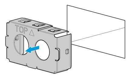
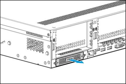
a. Insert the flathead screwdriver supplied with the server into the slot at the end of the handle on the mLOM Ethernet adapter blank and prize the blank to release it from the slot. Then hold the handle and pull the mLOM Ethernet adapter blank out of the slot, as shown in Figure 75.
Figure 75 Removing the mLOM Ethernet adapter blank
b. Insert the mLOM Ethernet adapter into the slot along the guide rails and then fasten the captive screws to secure the Ethernet adapter into place, as shown in Figure 76.
Some mLOM Ethernet adapters have only one captive screw. This example uses an mLOM with two captive screws.
Figure 76 Installing an mLOM Ethernet adapter
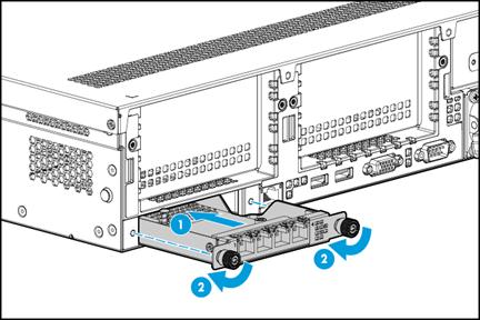
3. Connect network cables to the mLOM Ethernet adapter.
4. Connect the power cord. For more information, see "Connecting the power cord."
5. Power on the server. For more information, see "Powering on the server."
Verifying the installation
Log in to HDM to verify that the mLOM Ethernet adapter is operating correctly. For more information, see HDM online help.
Installing a PCIe Ethernet adapter
Procedure
1. Power off the server. For more information, see "Powering off the server."
2. Remove the server from the rack. For more information, see "Removing the server from a rack."
3. Remove the access panel. For more information, see "Replacing the access panel."
4. Install the PCIe Ethernet adapter. For more information, see "Installing riser cards and PCIe modules."
5. Connect network cables to the PCIe Ethernet adapter.
6. Install the access panel. For more information, see "Replacing the access panel."
7. Rack-mount the server. For more information, see "Rack-mounting the server."
8. Connect the power cord. For more information, see "Connecting the power cord."
9. Power on the server. For more information, see "Powering on the server."
Verifying the installation
Log in to HDM to verify that the PCIe Ethernet adapter is operating correctly. For more information, see HDM online help.
Installing SATA M.2 SSDs
You can use the following methods to install SATA M.2 SSDs:
· Install SATA M.2 SSDs in drive cage bay 1 at the front of an 8SFF server. For more information about the location of drive cage bay 1, see "Front panel view."
· Install SATA M.2 SSDs at the server rear by using an RC-M2-C M.2 transfer module installed in an RC-FHHL-2U-G3-1, RS-3*FHHL-R4900, RC-GPU/FHHL-2U-G3-1, or RC-2*FHFL-2U-G3 riser card.
Guidelines
To install SATA M.2 SSDs at the server rear, make sure the RC-M2-C M.2 transfer module is installed in the correct PCIe slot. Table 10 shows the available PCIe slots for installing an RC-M2-C M.2 transfer module.
Table 10 Available PCIe slots for installing an RC-M2-C M.2 transfer module
|
PCIe riser connector |
Riser card model |
PCIe slot |
|
Connector 1 or 2 |
RC-FHHL-2U-G3-1 |
2/5 |
|
3/6 |
||
|
RS-3*FHHL-R4900 |
1/4 |
|
|
2/5 |
||
|
3/6 |
||
|
RC-GPU/FHHL-2U-G3-1 |
2/5 |
|
|
3/6 |
||
|
Connector 1 |
RC-2*FHFL-2U-G3 |
1 |
|
2 |
Installing SATA M.2 SSDs at the server front
Guidelines
SATA M.2 SSDs and the SATA optical drive have the same installation location. You can install only one of them.
If you are installing two SATA M.2 SSDs, you must install a standard storage controller. In this condition, connect the data cable of the front drive backplane to the standard storage controller.
You can install a maximum of two SATA M.2 SSDs on an M.2 SSD expender module. The installation procedure for the two SSDs is the same. In this example, only one SATA M.2 SSD is installed.
Procedure
1. Power off the server. For more information, see "Powering off the server."
2. Remove the server from the rack. For more information, see "Removing the server from a rack."
3. Remove the access panel. For more information, see "Replacing the access panel."
4. Remove the chassis air baffle. For more information, see "Removing air baffles."
5. Remove the fan cage. For more information, see "Replacing the fan cage."
6. Remove the security bezel, if any. For more information, see "Replacing the security bezel."
7. Remove the blank from drive cage bay 1, as shown in Figure 89.
8. Remove the expander module blank, as shown in Figure 90.
9. Install the M.2 transfer module to drive cage bay 1, as shown in Figure 91.
10. Install the SATA M.2 SSD:
|
|
CAUTION: If you are installing only one SATA M.2 SSD, install it in the socket as shown in Figure 77 . |
a. Insert the connector of the SSD into the socket, and push down the other end of the SSD. Then, fasten the screw provided with the transfer module to secure the SSD into place, as shown in Figure 77.
Figure 77 Installing a SATA M.2 SSD
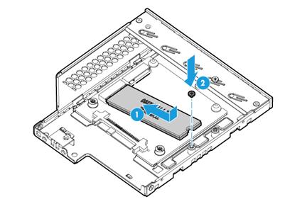
b. Connect the SATA M.2 SSD cable to the M.2 transfer module, as shown in Figure 78.
If you install only one SATA M.2 SSD, use the cable marked with P/N 0404A0ST. If you install two SATA M.2 SSDs, use the cable marked with P/N 0404A0TH.
Figure 78 Connecting the SATA M.2 SSD cable
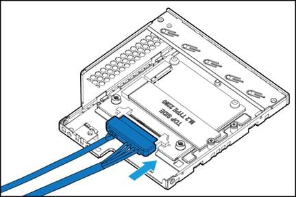
c. Install the M.2 transfer module. The installation procedure is the same for an M.2 transfer module and a SATA optical drive. For more information, see "Installing a SATA optical drive."
d. Connect the SATA M.2 SSD cable to the system board. For more information, see "Connecting the SATA M.2 SSD cable."
11. (Optional.) Install the removed security bezel. For more information, see "Installing the security bezel."
12. Install the removed fan cage. For more information, see "Installing fans."
13. Install the removed chassis air baffle. For more information, see "Installing air baffles."
14. Install the access panel. For more information, see "Replacing the access panel."
15. Rack-mount the server. For more information, see "Rack-mounting the server."
16. Connect the power cord. For more information, see "Connecting the power cord."
17. Power on the server. For more information, see "Powering on the server."
Installing SATA M.2 SSDs at the server rear
Guidelines
You can install a maximum of two SATA M.2 SSDs on an M.2 SSD expender module. The installation procedure for the two SSDs is the same. In this example, two SATA M.2 SSDs are installed.
Procedure
1. Power off the server. For more information, see "Powering off the server."
2. Remove the server from the rack. For more information, see "Removing the server from a rack."
3. Remove the access panel. For more information, see "Replacing the access panel."
4. Install the SATA M.2 SSD to the M.2 transfer module:
a. Insert the connector of the SSD into the socket, and push down the other end of the SSD. Then, fasten the screw supplied with the transfer module to secure the SSD into place, as shown in Figure 79.
|
|
CAUTION: To install only one SATA M.2 SSD, install it in the socket marked with J4. |
b. Connect the SATA M.2 SSD cable to the M.2 transfer module, as shown in Figure 79.
Figure 79 Installing a SATA M.2 SSD to the M.2 transfer module
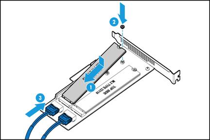
5. Install the transfer module to a riser card and then install the riser card on a PCIe riser connector. For more information, see "Installing riser cards and PCIe modules."
6. Connect the SATA M.2 SSD cable to the system board. For more information, see "Connecting the rear SATA M.2 SSD cable."
7. Install the access panel. For more information, see "Replacing the access panel."
8. Rack-mount the server. For more information, see "Rack-mounting the server."
9. Connect the power cord. For more information, see "Connecting the power cord."
10. Power on the server. For more information, see "Powering on the server."
Installing SD cards
Guidelines
The SD cards are hot swappable.
To achieve 1+1 redundancy and avoid storage space waste, install two SD cards with the same capacity as a best practice.
Procedure
1. Power off the server. For more information, see "Powering off the server."
2. Remove the server from the rack. For more information, see "Removing the server from a rack."
3. Remove the access panel. For more information, see "Replacing the access panel."
4. (Optional.) For the ease of installation, remove the riser card installed on PCIe riser connector 3, if any. For more information, see "Replacing a riser card and a PCIe module."
5. Orient the SD card with its golden plating facing the dual SD card extended module and insert the SD card into the slot, as shown in Figure 80.
Figure 80 Installing an SD card
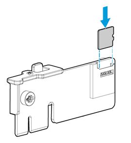
6. Align the two blue clips on the extended module with the bracket on the power supply bay, and slowly insert the extended module downwards until it snaps into space, as shown in Figure 81.
Figure 81 Installing the dual SD card extended module

7. (Optional.) Install the removed riser card on PCIe riser connector 3. For more information, see "Installing riser cards and PCIe modules."
8. Install the access panel. For more information, see "Replacing the access panel."
9. Rack-mount the server. For more information, see "Rack-mounting the server."
10. Connect the power cord. For more information, see "Connecting the power cord."
11. Power on the server. For more information, see "Powering on the server."
Installing an NVMe SSD expander module
Guidelines
A riser card is required when you install an NVMe SSD expander module.
An NVMe SSD expander module is required only when NVMe drives are installed. For configurations that require an NVMe expander module, see "Drive configurations and numbering."
Procedure
The procedure is the same for installing a 4-port NVMe SSD expander module and an 8-port NVMe SSD expander module. This section uses a 4-port NVMe SSD expander module as an example.
To install an NVMe SSD expander module:
1. Power off the server. For more information, see "Powering off the server."
2. Remove the server from the rack. For more information, see "Removing the server from a rack."
3. Remove the access panel. For more information, see "Replacing the access panel."
4. Remove the chassis air baffle. For more information, see "Removing air baffles."
5. Remove the fan cage. For more information, see "Replacing the fan cage."
6. Connect the four NVMe data cables to the NVMe SSD expander module, as shown in Figure 82.
Figure 82 Connecting an NVMe data cable to the NVMe SSD expander module
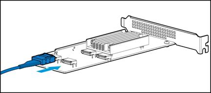
7. Install the NVMe SSD expander module to the server by using a PCIe riser card. For more information, see "Installing riser cards and PCIe modules."
8. Connect the NVMe data cables to the drive backplane. For more information, see "8SFF server."
Make sure you connect the corresponding peer ports with the correct NVMe data cable. For more information, see "Connecting drive cables."
9. Install the removed fan cage. For more information, see "Installing fans."
10. Install the removed chassis air baffle. For more information, see "Installing air baffles."
11. Install the access panel. For more information, see "Replacing the access panel."
12. Rack-mount the server. For more information, see "Rack-mounting the server."
13. Connect the power cord. For more information, see "Connecting the power cord."
14. Power on the server. For more information, see "Powering on the server."
Verifying the installation
Log in to HDM to verify that the NVMe SSD expander module is operating correctly. For more information, see HDM online help.
Installing the NVMe VROC module
1. Identify the NVMe VROC module connector on the system board. For more information, see "System board components."
2. Power off the server. For more information, see "Powering off the server."
3. Remove the server from the rack. For more information, see "Removing the server from a rack."
4. Remove the access panel. For more information, see "Replacing the access panel."
5. Remove the power supply air baffle. For more information, see "Removing air baffles."
6. Insert the NVMe VROC module onto the NVMe VROC module connector on the system board, as shown in Figure 83.
Figure 83 Installing the NVMe VROC module
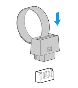
7. Install the removed power supply air baffle. For more information, see "Installing air baffles."
8. Install the access panel. For more information, see "Replacing the access panel."
9. Rack-mount the server. For more information, see "Rack-mounting the server."
10. Connect the power cord. For more information, see "Connecting the power cord."
11. Power on the server. For more information, see "Powering on the server."
Installing a front or rear drive cage
Only 12LFF or 25SFF servers support installing drives at the server rear.
For more information about drive configuration, see "Drive configurations and numbering."
If drives are installed in the rear drive cage, make sure all the six fans are present before you power on the server. For more information about installing fans, see "Installing fans."
Installing the rear 2SFF drive cage
1. Power off the server. For more information, see "Powering off the server."
2. Remove the server from the rack. For more information, see "Removing the server from a rack."
3. Remove the access panel. For more information, see "Replacing the access panel."
4. Remove the chassis air baffle. For more information, see "Removing air baffles."
5. Remove the fan cage. For more information, see "Replacing the fan cage."
6. Remove the 4SFF drive cage blank over the power supplies, as shown in Figure 41.
7. Install the riser card bracket, as shown in Figure 48.
8. Install the rear 2SFF drive cage:
a. Aligning the clip at the cage side with the edge of the riser card bracket, place the drive cage in the chassis, as shown by callout 1 in Figure 84.
b. Use screws to secure the drive cage, as shown in Figure 84.
Figure 84 Installing the rear 2SFF drive cage
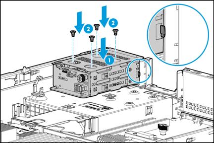
9. Install the blank for PCIe riser connector 3, as shown in Figure 85.
Figure 85 Installing the blank for PCIe riser connector 3
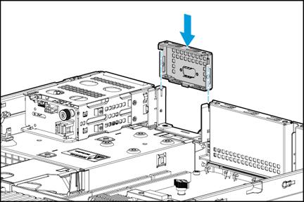
10. Connect AUX signal cable, data cable, and power cord to the rear 2SFF drive backplane. For more information, see "Rear 2SFF SAS/SATA drive cabling."
11. Install drives in the rear 2SFF drive cage. For more information, see "Installing SAS/SATA drives."
12. Install the removed fan cage. To install drives in the rear drive cage, make sure each fan bay is installed with a fan. For more information, see "Installing fans."
13. Install the removed chassis air baffle. For more information, see "Installing air baffles."
14. Install the access panel. For more information, see "Replacing the access panel."
15. Rack-mount the server. For more information, see "Rack-mounting the server."
16. Connect the power cord. For more information, see "Connecting the power cord."
17. Power on the server. For more information, see "Powering on the server."
Installing the rear 4SFF drive cage
1. Power off the server. For more information, see "Powering off the server."
2. Remove the server from the rack. For more information, see "Removing the server from a rack."
3. Remove the access panel. For more information, see "Replacing the access panel."
4. Remove the chassis air baffle. For more information, see "Removing air baffles."
5. Remove the fan cage. For more information, see "Replacing the fan cage."
6. Remove all drive blanks from the rear 4SFF drive cage, if any. For more information, see "Installing SAS/SATA drives."
7. Remove the 4SFF drive cage blank over the power supplies, as shown in Figure 41.
8. Install the rear 4SFF drive cage:
a. Aligning the clip at the cage side with the edge of the bracket in the chassis, place the drive cage in the chassis, as shown by callout in Figure 86.
b. Use screws to secure the drive cage, as shown in Figure 86.
Figure 86 Installing the rear 4SFF drive cage
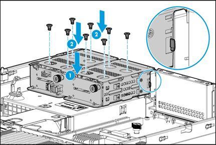
9. Connect AUX signal cable, data cable, and power cord to the rear 4SFF drive backplane. For more information, see "Connecting drive cables."
10. Install drives in the rear 4SFF drive cage. For more information, see "Installing SAS/SATA drives."
11. Install the removed fan cage. To install drives in the rear drive cage, make sure each fan bay is installed with a fan. For more information, see "Installing fans."
12. Install the removed chassis air baffle. For more information, see "Installing air baffles."
13. Install the access panel. For more information, see "Replacing the access panel."
14. Rack-mount the server. For more information, see "Rack-mounting the server."
15. Connect the power cord. For more information, see "Connecting the power cord."
16. Power on the server. For more information, see "Powering on the server."
Installing the rear 2LFF drive cage
1. Power off the server. For more information, see "Powering off the server."
2. Remove the server from the rack. For more information, see "Removing the server from a rack."
3. Remove the access panel. For more information, see "Replacing the access panel."
4. Remove the chassis air baffle. For more information, see "Removing air baffles."
5. Remove the fan cage. For more information, see "Replacing the fan cage."
6. Remove the blank for PCIe riser connector 2, as shown in Figure 31.
7. Place the rear 2LFF drive cage in the chassis and use screws to secure it into place, as shown in Figure 87.
Figure 87 Installing the rear 2LFF drive cage
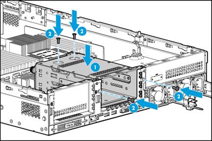
8. Connect AUX signal cable, data cable, and power cord to the rear 2LFF drive backplane. For more information, see "Connecting drive cables."
9. Install drives in the rear 2LFF drive cage. For more information, see "Installing SAS/SATA drives."
10. Install the removed fan cage. For more information, see "Installing fans."
11. Install the removed chassis air baffle. For more information, see "Installing air baffles."
12. Install the access panel. For more information, see "Replacing the access panel."
13. Rack-mount the server. For more information, see "Rack-mounting the server."
14. Connect the power cord. For more information, see "Connecting the power cord."
15. Power on the server. For more information, see "Powering on the server."
Installing the rear 4LFF drive cage
1. Power off the server. For more information, see "Powering off the server."
2. Remove the server from the rack. For more information, see "Removing the server from a rack."
3. Remove the access panel. For more information, see "Replacing the access panel."
4. Remove the chassis air baffle. For more information, see "Removing air baffles."
5. Remove the fan cage. For more information, see "Replacing the fan cage."
6. Remove all drive blanks from the 4LFF drive cage, if any. For more information, see "Installing SAS/SATA drives."
7. Remove the blanks for PCIe riser connectors 1 and 2, as shown in Figure 27 and Figure 31.
8. Place the rear 4LFF drive cage into the chassis and use screws to secure it into place, as shown in Figure 88.
Figure 88 Installing the rear 4LFF drive cage
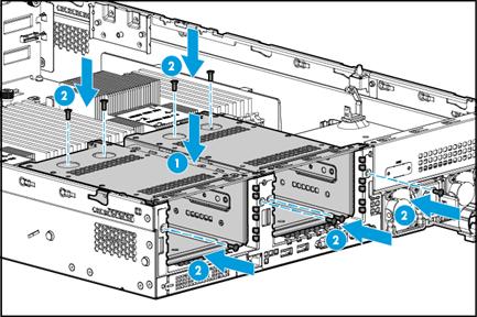
9. Connect AUX signal cable, data cable, and power cord to the rear 4LFF drive backplane. For more information, see "Rear 4LFF SAS/SATA drives."
10. Install drives in the rear 4LFF drive cage. For more information, see "Installing SAS/SATA drives."
11. Install the removed fan cage. For more information, see "Installing fans."
12. Install the removed chassis air baffle. For more information, see "Installing air baffles."
13. Install the access panel. For more information, see "Replacing the access panel."
14. Rack-mount the server. For more information, see "Rack-mounting the server."
15. Connect the power cord. For more information, see "Connecting the power cord."
16. Power on the server. For more information, see "Powering on the server."
Installing a front 8SFF drive cage
Preparing for the installation
Use Table 11 to determine the location of the front 8SFF drive cage you are installing depending on the type of the drive cage. For more information about the locations of drive cage bays, see "Front panel view."
Table 11 8SFF drive cage installation locations
|
8SFF drive cage |
Installation location |
|
HDD-Cage-8SFF-2U |
Drive cage bay 1 for 8SFF SAS/SATA drives |
|
HDD-Cage-8SFF-2U-NVMe-1 |
Drive cage bay 1 for 8SFF NVMe SSDs |
|
HDD-Cage-8SFF-2U-NVMe-2 |
Drive cage bay 2 for 8SFF NVMe SSDs |
|
HDD-Cage-8SFF-2U-2 |
Drive cage bay 2 for 8SFF SAS/SATA drives |
|
HDD-Cage-8SFF-2U-NVMe-3 |
Drive cage bay 3 for 8SFF NVMe SSDs |
|
HDD-Cage-8SFF-2U-3 |
Drive cage bay 3 for 8SFF SAS/SATA drives |
|
HDDCage-8SFF-8NVMe-2U |
Drive cage bays 1 to 3 for 8SFF NVMe SSDs |
Procedure
The procedure is the same for installing an 8SFF drive cage in different installation locations. This section installs a drive cage in drive cage bay 1 for 8SFF SAS/SATA drives.
To install a front 8SFF drive cage:
1. Power off the server. For more information, see "Powering off the server."
2. Remove the server from the rack. For more information, see "Removing the server from a rack."
3. Remove the security bezel, if any. For more information, see "Replacing the security bezel."
4. Install the front 8SFF drive cage:
a. Remove the drive cage bay blank over the drive cage bay, as shown in Figure 89.
b. Install the drive cage into the server, as shown in Figure 91.
5. Install drives in the front 8SFF drive cage. For more information, see "Installing SAS/SATA drives."
6. Paste the drive label on the server's front panel above the drive cage bay.
7. Connect AUX signal cable, data cable, and power cord to the front 8SFF drive backplane. For more information, see "Front 8SFF SAS/SATA drive cabling."
8. Install the removed security bezel. For more information, see "Installing the security bezel."
9. Rack-mount the server. For more information, see "Rack-mounting the server."
10. Connect the power cord. For more information, see "Connecting the power cord."
11. Power on the server. For more information, see "Powering on the server."
Installing an optical drive
Preparing for the installation
Use Table 12 to determine the location of the optical drive you are installing depending on the type of the optical drive.
Table 12 Optical drive installation locations
|
Optical drive |
Installation location |
|
USB 2.0 optical drive |
Connect the optical drive to a USB 2.0 or USB 3.0 connector on the server. |
|
SATA optical drive |
Only the 8SFF server supports the SATA optical drive. Install the optical drive in drive cage bay 1 of the 8SFF server. For the location of drive cage bay 1, see "Front panel view." |
Installing a SATA optical drive
1. Power off the server. For more information, see "Powering off the server."
2. Remove the server from the rack. For more information, see "Removing the server from a rack."
3. Remove the access panel. For more information, see "Replacing the access panel."
4. Remove the chassis air baffle. For more information, see "Removing air baffles."
5. Remove the fan cage. For more information, see "Replacing the fan cage."
6. Remove the security bezel, if any. For more information, see "Replacing the security bezel."
7. Remove the screws that secure the drive cage bay blank over drive cage bay 1, and then push the blank from the inside of the chassis to remove it, as shown in Figure 89.
Figure 89 Removing the blank in drive cage bay 1
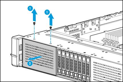
8. Remove the optical drive blank from the optical drive enablement option:
a. Press the clip on the right side of the optical drive blank, as shown by callout 1 in Figure 90. The optical drive blank will pop out from the enablement option.
b. Pull the blank out of the enablement option, as shown by callout 2 in Figure 90.
Figure 90 Removing the optical drive blank from the optical drive enablement option
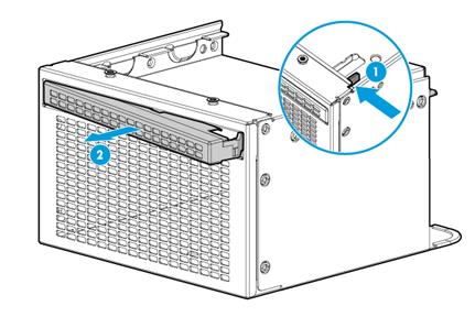
9. Insert the optical drive enablement option in drive cage bay 1 and fasten the screws to secure the option into place, as shown in Figure 91.
Figure 91 Installing the optical drive enablement option
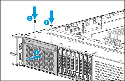
10. Insert the SATA optical drive into the optical drive slot, and fasten the screw to secure the optical drive into place, as shown in Figure 92.
Figure 92 Installing the optical drive
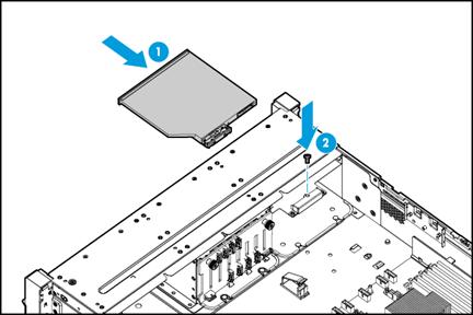
11. Connect the SATA optical drive cable. For more information, see "Connecting the SATA optical drive cable."
12. Install the removed security bezel. For more information, see "Installing the security bezel."
13. Install the removed fan cage. For more information, see "Installing fans."
14. Install the removed chassis air baffle. For more information, see "Installing air baffles."
15. Install the access panel. For more information, see "Replacing the access panel."
16. Rack-mount the server. For more information, see "Rack-mounting the server."
17. Connect the power cord. For more information, see "Connecting the power cord."
18. Power on the server. For more information, see "Powering on the server."
Installing a diagnostic panel
Preparing for the installation
For the installation location of the diagnostic panel, see "Front panel view."
Use Table 13 to identify the diagnostic panel to use and the diagnostic panel cable before you install the diagnostic panel.
Table 13 Available diagnostic panel and diagnostic panel cable
|
Diagnostic panel |
Available server model |
Cable |
|
SD-SFF-A |
25SFF server |
The diagnostic panel comes with two cables (P/N 0404A0T1 and P/N 0404A0SP). Determine the cable to use according to the drive backplane: · If drive backplane BP-25SFF-R4900 25SFF is used, use the cable with P/N 0404A0T1. · If drive backplane BP2-25SFF-2U-G3 is used, use the cable with P/N 0404A0SP. |
|
SD-SFF-B |
8SFF server |
The diagnostic panel comes with only one cable (P/N 0404A0T1). |
|
SD-LFF-G3-A |
· 8LFF server · 12LFF server |
The diagnostic panel comes with two cables (P/N 0404A0T1 and P/N 0404A0SP). Determine the cable to use according to the drive backplane: · For the 8LFF server, use the cable with P/N 0404A0T1. · For the 12LFF server: ¡ If drive backplane BP-12LFF-NVMe-2U-G3, BP2-12LFF-2U-G3, or BP-12LFF-G3 is used, use the cable with P/N 0404A0SP. ¡ If drive backplane BP-12LFF-R4900 is used, use the cable with P/N 0404A0T1. |
Installing the SD-SFF-A SFF diagnostic panel
1. Power off the server. For more information, see "Powering off the server."
2. Remove the server from the rack. For more information, see "Removing the server from a rack."
3. Remove the access panel. For more information, see "Replacing the access panel."
4. Remove the chassis air baffle. For more information, see "Removing air baffles."
5. Remove the fan cage. For more information, see "Replacing the fan cage."
6. Remove the security bezel, if any. For more information, see "Replacing the security bezel."
7. Remove the blank or drive from the slot in which the diagnostic panel will be installed. For more information, see "Replacing a SAS/SATA drive."
8. If the BP-25SFF-R4900 25SFF drive backplane is used, install the diagnostic panel as follows:
a. Connect one end of the cable (P/N 0404A0T1) to the diagnostic panel, as shown in Figure 99.
Figure 93 Connecting the diagnostic panel cable
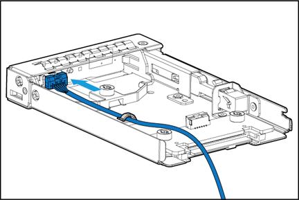
a. Push the diagnostic panel into the slot until it snaps into place, as shown in Figure 100.
Figure 94 Installing the SFF diagnostic panel
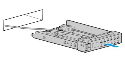
a. Connect the other end of the diagnostic panel cable to the diagnostic panel connector on the system board. For more information, see "Connecting the diagnostic panel cable."
9. If BP2-25SFF-2U-G3 25SFF drive backplane is used, install the diagnostic panel as follows:
a. Connect one end of the cable (P/N 0404A0SP) to the front panel of the diagnostic panel and the other end to the transfer module of the diagnostic panel, as shown in Figure 95.
Figure 95 Connecting the diagnostic panel cable

b. Push the diagnostic panel into the slot until it snaps into place, as shown in Figure 96.
Figure 96 Installing the SFF diagnostic panel

10. Install the removed security bezel. For more information, see "Installing the security bezel."
11. Install the removed fan cage. For more information, see "Installing fans."
12. Install the removed chassis air baffle. For more information, see "Installing air baffles."
13. Install the access panel. For more information, see "Replacing the access panel."
14. Rack-mount the server. For more information, see "Rack-mounting the server."
15. Connect the power cord. For more information, see "Connecting the power cord."
16. Power on the server. For more information, see "Powering on the server."
Installing the SD-SFF-B SFF diagnostic panel
1. Power off the server. For more information, see "Powering off the server."
2. Remove the server from the rack. For more information, see "Removing the server from a rack."
3. Remove the access panel. For more information, see "Replacing the access panel."
4. Remove the chassis air baffle. For more information, see "Removing air baffles."
5. Remove the fan cage. For more information, see "Replacing the fan cage."
6. Remove the security bezel, if any. For more information, see "Replacing the security bezel."
7. Remove the blank or drive from the slot in which the diagnostic panel will be installed and then install the 1SFF cage provided with the diagnostic panel into the slot.
a. Remove the screw that secures the blank, and then push the blank out of the chassis from the inside of the chassis, as shown in Figure 97.
b. Insert the 1SFF cage provided with the diagnostic panel into the slot and secure the 1SFF cage with the fastening screw, as shown in Figure 98.
Figure 98 Installing the 1SFF cage
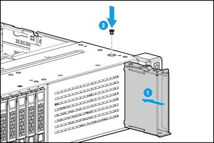
8. Install the diagnostic panel:
a. Connect the diagnostic panel cable (P/N 0404A0T1) to the diagnostic panel, as shown in Figure 99.
Figure 99 Connecting the diagnostic panel cable

b. Push the diagnostic panel into the slot until it snaps into place, as shown in Figure 100.
Figure 100 Installing the SFF diagnostic panel

c. Connect the other end of the diagnostic panel cable to the diagnostic panel connector on the system board. For more information, see "Connecting the diagnostic panel cable."
9. Install the removed security bezel. For more information, see "Installing the security bezel."
10. Install the removed fan cage. For more information, see "Installing fans."
11. Install the removed chassis air baffle. For more information, see "Installing air baffles."
12. Install the access panel. For more information, see "Replacing the access panel."
13. Rack-mount the server. For more information, see "Rack-mounting the server."
14. Connect the power cord. For more information, see "Connecting the power cord."
15. Power on the server. For more information, see "Powering on the server."
Installing the SD-LFF-G3-A LFF diagnostic panel
1. Power off the server. For more information, see "Powering off the server."
2. Remove the server from the rack. For more information, see "Removing the server from a rack."
3. Remove the access panel. For more information, see "Replacing the access panel."
4. Remove the chassis air baffle. For more information, see "Removing air baffles."
5. Remove the fan cage. For more information, see "Replacing the fan cage."
6. Remove the security bezel, if any. For more information, see "Replacing the security bezel."
7. Remove the blank or drive from the slot in which the diagnostic panel will be installed, as follows:
¡ For the 8LFF server, remove the blank from the slot. As shown in Figure 101, insert a tweezer into ventilation holes on the blank to prize up the clips at both sides in the blank. Then push the blank out of the chassis from the inside of the chassis.
Figure 101 Removing the diagnostic panel blank

¡ For the 12LFF server, remove the drive from the diagnostic panel slot at the top left or bottom right. For more information about the location of the diagnostic panel slot, see "Front panel view." For more information about removing a drive, see "Replacing a SAS/SATA drive."
8. For an 8LFF or 12LFF server with the BP-12LFF-R4900 drive backplane, install the diagnostic panel as follows:
a. Connect one end of the cable (P/N 0404A0T1) to the diagnostic panel, as shown in Figure 102.
Figure 102 Connecting the diagnostic panel cable
a. Push the diagnostic panel into the slot until it snaps into place, as shown in Figure 103.
Figure 103 Installing the LFF diagnostic panel
a. Connect the other end of the diagnostic panel cable to the diagnostic panel connector on the system board. For more information, see "Connecting the diagnostic panel cable."
9. For a 12LFF server with the BP-12LFF-NVMe-2U-G3, BP2-12LFF-2U-G3, or BP-12LFF-G3 drive backplane, install the diagnostic panel as follows:
a. Connect one end of the cable (P/N 0404A0SP) to the front panel of the diagnostic panel and the other end to the transfer module of the diagnostic panel, as shown in Figure 104.
Figure 104 Connecting the diagnostic panel cable
a. Push the diagnostic panel into the slot until it snaps into place, as shown in Figure 105.
Figure 105 Installing the LFF diagnostic panel
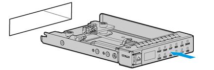
10. Install the removed security bezel. For more information, see "Installing the security bezel."
11. Install the removed fan cage. For more information, see "Installing fans."
12. Install the removed chassis air baffle. For more information, see "Installing air baffles."
13. Install the access panel. For more information, see "Replacing the access panel."
14. Rack-mount the server. For more information, see "Rack-mounting the server."
15. Connect the power cord. For more information, see "Connecting the power cord."
16. Power on the server. For more information, see "Powering on the server."
Installing a serial label pull tab module
Guidelines
This task is applicable only to 8SFF and 25SFF servers.
The 8LFF and 12LFF servers do not support the serial label pull tab module. If the LFF diagnostic panel is installed, the 8LFF or 12LFF server provides a serial label pull tab integrated with the diagnostic panel. For more information about diagnostic panel installation, see "Installing the SD-LFF-G3-A LFF diagnostic panel."
Procedure
If sufficient space is available for installation, you can install the serial label pull tab module without powering off the server or removing the server from the rack. The following procedure is provided based on the assumption that no sufficient space is available for replacement.
To install a serial label pull tab module:
1. Power off the server. For more information, see "Powering off the server."
2. Remove the server from the rack. For more information, see "Removing the server from a rack."
3. Remove the security bezel, if any. For more information, see "Replacing the security bezel."
4. Remove the blank or drive from the slot in which the serial label pull tab module will be installed, as follows:
¡ For the 8SFF server, remove the blank from the slot, and then install the 1SFF cage provided with the serial label pull tab module into the slot.
As shown in Figure 106, remove the screw that secures the blank, and then push the blank out of the chassis from the inside of the chassis. Then insert the 1SFF cage provided with the serial label pull tab module into the slot and secure the 1SFF cage with the fastening screw, as shown in Figure 107.

Figure 107 Installing the 1SFF cage
¡ For the 25SFF server, remove the drive from the slot. For more information, see "Replacing a SAS/SATA drive."
5. Install the serial label pull tab module. The installation procedure is the same for the serial label pull tab module and the SFF diagnostic panel. For more information, see "Installing the SD-SFF-B SFF diagnostic panel."
6. Install the removed security bezel. For more information, see "Installing the security bezel."
7. Rack-mount the server. For more information, see "Rack-mounting the server."
8. Connect the power cord. For more information, see "Connecting the power cord."
9. Power on the server. For more information, see "Powering on the server."
Installing fans
Guidelines
The fans are hot swappable. If sufficient space is available for installation, you can install fans without powering off the server or removing the server from the rack. The following procedure is provided based on the assumption that no sufficient space is available for replacement.
The server provides six fan bays. You must install fans in all fan bays in any of the following conditions:
· Two processors are present.
· One processor is present and NVMe drives are installed at the front for the 8SFF/12LFF/25SFF server.
· One processor is present and drives are installed at the rear for the 12LFF/25SFF server.
· One processor is present and one of the following GPU modules is installed:
¡ GPU-M4-1.
¡ GPU-K80-1.
¡ GPU-M60-1-X.
¡ GPU-P4-X.
¡ GPU-T4.
¡ GPU-P40-X.
¡ GPU-M10-X.
¡ GPU-P100.
¡ GPU-V100-32G.
¡ GPU-V100.
¡ GPU-MLU100-D3.
In any other conditions, you must install fans in fan bays 3 through 6 and the remaining fan bays can be empty. If a fan bay is empty, make sure a fan blank is installed. For the locations of fans in the server, see "Fans."
The fans support N+1 redundancy:
· If one fan fails, the other fans speed up and the Health LED on the front panel flashes amber at 1 Hz to indicate that a major alarm has occurred.
· If two fans fail, the Health LED on the front panel flashes red at 1 Hz to indicate that a critical alarm has occurred. You need to replace the faulty fans immediately because the server will be powered off one minute after the severe alarm was generated.
During system POST and operation, the server will be powered off if the temperature detected by any sensor in the server reaches the critical alarm threshold.
Procedure
1. Power off the server. For more information, see "Powering off the server."
2. Remove the server from the rack. For more information, see "Removing the server from a rack."
3. Remove the access panel. For more information, see "Replacing the access panel."
4. Install a fan:
a. Lift a fan blank to remove it, as shown in Figure 108.
Figure 108 Removing a fan blank
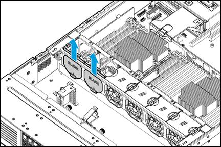
b. Insert a fan into the slot and push it until it snaps into place, as shown in Figure 109.
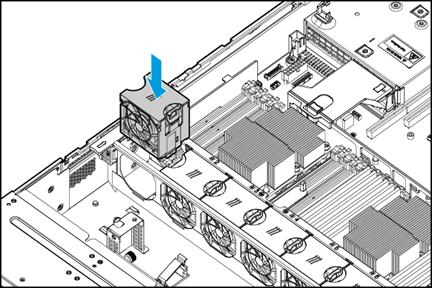
5. Install the access panel. For more information, see "Replacing the access panel."
6. Rack-mount the server. For more information, see "Installing the server."
7. Connect the power cord. For more information, see "Connecting the power cord."
8. Power on the server. For more information, see "Powering on the server."
Verifying the installation
Log in to HDM to verify that the fan is operating correctly. For more information, see HDM online help.
Installing processors
Guidelines
· To avoid damage to the processors or system board, only H3C-authorized personnel and professional server engineers are allowed to install a processor.
· For the server to operate correctly, make sure processor 1 is in position. For more information about processor locations, see "System board components."
· Make sure the processors are the same model if two processors are installed.
· The pins in the processor socket are very fragile. Make sure a processor socket cover is installed on an empty processor socket.
· To avoid ESD damage, put on an ESD wrist strap before performing this task, and make sure the wrist strap is reliably grounded.
Procedure
1. Back up all server data.
2. Power off the server. For more information, see "Powering off the server."
3. Remove the server from the rack. For more information, see "Removing the server from a rack."
4. Remove the access panel. For more information, see "Replacing the access panel."
5. Remove the chassis air baffle. For more information, see "Removing air baffles."
6. Install a processor onto the retaining bracket:
|
|
CAUTION: To avoid damage to the processor, always hold the processor by its edges. Never touch the gold contacts on the processor bottom. |
a. As shown by callout 1 in Figure 110, align the small triangle on the processor with the alignment triangle in the retaining bracket, and align the guide pin on the bracket with the notch on the triangle side of the processor.
b. As shown by callout 2 in Figure 110, lower the processor gently and make sure the guide pins on the opposite side of the bracket fit snugly into notches on the processor.
Figure 110 Installing a processor onto the retaining bracket
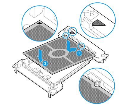
7. Install the retaining bracket onto the heatsink:
|
|
CAUTION: When you remove the protective cover over the heatsink, be careful not to touch the thermal grease on the heatsink. |
a. Lift the cover straight up until it is removed from the heatsink, as shown in Figure 111.
Figure 111 Removing the protective cover
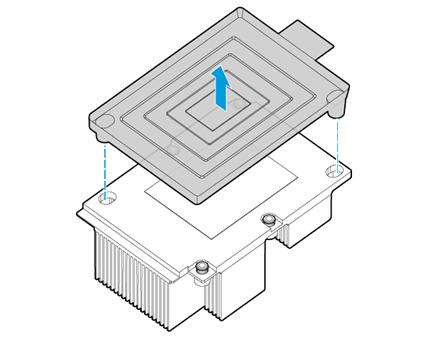
b. Install the retaining bracket onto the heatsink. As shown in Figure 112, align the alignment triangle on the retaining bracket with the cut-off corner of the heatsink. Place the bracket on top of the heatsink, with the four corners of the bracket clicked into the four corners of the heatsink.
Figure 112 Installing the processor onto the heatsink
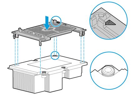
8. Remove the processor socket cover.
|
|
CAUTION: · Take adequate ESD preventive measures when you remove the processor socket cover. · Be careful not to touch the pins on the processor socket, which are very fragile. Damage to pins will incur system board replacement. · Keep the pins on the processor socket clean. Make sure the socket is free from dust and debris. |
Hold the cover by the notches on its two edges and lift it straight up and away from the socket. Put the cover away for future use.
Figure 113 Removing the processor socket cover
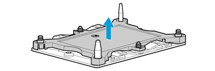
9. Install the retaining bracket and heatsink onto the server, as shown in Figure 114.
a. Place the heatsink on the processor socket. Make sure the alignment triangle on the retaining bracket and the pin holes in the heatsink are aligned with the cut-off corner and guide pins of the processor socket, respectively, as shown by callout 1.
b. Fasten the captive screws on the heatsink in the sequence shown by callouts 2 through 5.
|
|
CAUTION: To avoid poor contact between the processor and the system board or damage to the pins in the processor socket, tighten the screws to a torque value of 1.4 Nm (12 in-lbs). |
Figure 114 Attaching the retaining bracket and heatsink to the processor socket

10. Install fans. For more information, see "Installing fans."
11. Install DIMMs. For more information, see "Installing DIMMs."
12. Install the chassis air baffle. For more information, see "Installing air baffles."
13. Install the access panel. For more information, see "Replacing the access panel."
14. Rack-mount the server. For more information, see "Installing the server."
15. Connect the power cord. For more information, see "Connecting the power cord."
16. Power on the server. For more information, see "Powering on the server."
Verifying the installation
Log in to HDM to verify that the processor is operating correctly. For more information, see HDM online help.
Installing DIMMs
The server supports DCPMMs and DRAM DIMMs (both LRDIMM and RDIMM supported). Compared with DRAM DIMMs, DCPMMs provide larger capacity and can protect data from getting lost in case of unexpected system failures.
Both DCPMMs and DRAM DIMMs are referred to as DIMMs in this document, unless otherwise stated.
Guidelines
|
|
WARNING! The DIMMs are not hot swappable. |
You can install a maximum of 12 DIMMs for each processor, six DIMMs per memory controller. For more information, see "DIMM slots."
For a DIMM to operate at 2933 MHz, make sure the following conditions are met:
· Use Cascade Lake processors that support 2933 MHz data rate.
· Use DIMMs with a maximum of 2933 MHz data rate.
· Install a maximum of one DIMM per channel.
The supported DIMMs vary by processor model, as shown in Table 14.
Table 14 Supported DIMMs of a processor
|
Processor |
Supported DIMMs |
|
Skylake |
Only DRAM DIMMs. |
|
Cascade Lake |
· Only DRAM DIMMs. · Mixture of DCPMM and DRAM DIMMs. |
|
Jintide-C series |
Only DRAM DIMMs. |
Guidelines for installing only DRAM DIMMs
When you install only DRAM DIMMs, follow these restrictions and guidelines:
· Make sure the corresponding processor is present before powering on the server.
· Make sure all DRAM DIMMs installed on the server have the same specifications.
· For the memory mode setting to take effect, make sure the following DIMM installation requirements are met when you install DRAM DIMMs for a processor:
|
Memory mode |
DIMM requirements |
|
Independent |
· If only one processor is present, see Figure 115. · If two processors are present, see Figure 116. |
|
Mirror Partial Mirror |
· A minimum of two DIMMs for a processor. · This mode does not support DIMM population schemes that are not recommended in Figure 115 and Figure 116. DIMM installation scheme: ¡ If only processor 1 is present, see Figure 115. ¡ If two processors are present, see Figure 116. |
|
Memory Rank Sparing |
· A minimum of 2 ranks per channel. DIMM installation scheme: ¡ If only one processor is present, see Figure 115. ¡ If two processors are present, see Figure 116. |
|
|
NOTE: If the DIMM configuration does not meet the requirements for the configured memory mode, the system uses the default memory mode (Independent mode). For more information about memory modes, see the BIOS user guide for the server. |
Figure 115 DIMM population schemes (one processor present)
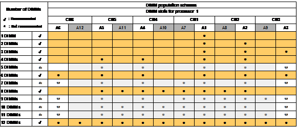
Figure 116 DIMM population schemes (two processors present)
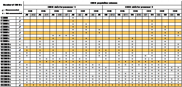
Guidelines for mixture installation of DCPMMs and DRAM DIMMs
When you install DRAM DIMMs and DCPMMs on the server, follow these restrictions and guidelines:
· Make sure the corresponding processors are present before powering on the server.
· Make sure all DRAM DIMMs have the same product code and all DCPMMs have the same product code.
· As a best practice to increase memory bandwidth, install DRAM and DCPMM DIMMs in different channels.
· A channel supports a maximum of one DCPMM.
· As a best practice, install DCPMMs symmetrically across the two memory processing units for a processor.
· To install both DRAM DIMM and DCPMM in a channel, install the DRAM DIMM in the white slot and the DCPMM in the black slot. To install only one DIMM in a channel, install the DIMM in the white slot if the DIMM is DCPMM.
Procedure
1. Power off the server. For more information, see "Powering off the server."
2. Remove the server from the rack. For more information, see "Removing the server from a rack."
3. Remove the access panel. For more information, see "Replacing the access panel."
4. Remove the chassis air baffle. For more information, see "Removing air baffles."
5. Install a DIMM:
a. Identify the location of the DIMM slot.
Figure 117 DIMM slots numbering

b. Open the DIMM slot latches.
c. Align the notch on the DIMM with the connector key in the DIMM slot and press the DIMM into the socket until the latches lock the DIMM in place, as shown in Figure 118.
To avoid damage to the DIMM, do not use force to press the DIMM into the socket when you encounter resistance. Instead, re-align the notch with the connector key, and then reinsert the DIMM again.
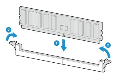
6. Install the chassis air baffle. For more information, see "Installing air baffles."
7. Install the access panel. For more information, see "Replacing the access panel."
8. Rack-mount the server. For more information, see "Installing the server."
9. Connect the power cord. For more information, see "Connecting the power cord."
10. Power on the server. For more information, see "Powering on the server."
Verifying the installation
Use one of the following methods to verify that the memory size is correct:
· Access the GUI or CLI of the server:
¡ In the GUI of a windows OS, click the Start icon in the bottom left corner, enter msinfo32 in the search box, and then click the msinfo32 item.
¡ In the CLI of a Linux OS, execute the cat /proc/meminfo command.
· Log in to HDM. For more information, see HDM online help.
· Access the BIOS. For more information, see the BIOS user guide for the server.
If the memory size is incorrect, re-install or replace the DIMM.
|
|
NOTE: It is normal that the CLI or GUI of the server OS displays a smaller memory size than the actual size if the mirror, partial mirror, or memory rank sparing memory mode is enabled. In this situation, you can verify the memory size from HDM or BIOS. |
Installing and setting up a TCM or TPM
Installation and setup flowchart
Figure 119 TCM/TPM installation and setup flowchart
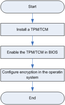
Installing a TCM or TPM
Guidelines
· Do not remove an installed TCM or TPM. Once installed, the module becomes a permanent part of the system board.
· When installing or replacing hardware, H3C service providers cannot enable the TCM or TPM or the encryption technology. For security reasons, only the customer can enable these features.
· When replacing the system board, do not remove the TCM or TPM from the system board. H3C will provide a TCM or TPM with the spare system board for system board or module replacement.
· Any attempt to remove an installed TCM or TPM from the system board breaks or disfigures the TCM or TPM security rivet. Upon locating a broken or disfigured rivet on an installed TCP or TPM, administrators should consider the system compromised and take appropriate measures to ensure the integrity of the system data.
· H3C is not liable for blocked data access caused by improper use of the TCM or TPM. For more information, see the encryption technology feature documentation provided by the operating system.
Procedure
The installation procedure is the same for a TPM and a TCM. The following information uses a TPM to show the procedure.
To install a TPM:
1. Power off the server. For more information, see "Powering off the server."
2. Remove the server from the rack. For more information, see "Removing the server from a rack."
3. Remove the access panel. For more information, see "Replacing the access panel."
4. Remove the PCIe modules that might hinder TPM installation. For more information, see "Replacing a riser card and a PCIe module."
5. Install the TPM:
a. Press the TPM into the TPM connector on the system board, as shown in Figure 120.
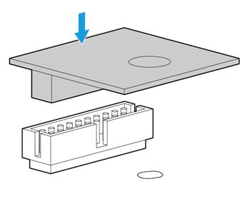
b. Insert the rivet pin as shown by callout 1 in Figure 121.
c. Insert the security rivet into the hole in the rivet pin and press the security rivet until it is firmly seated, as shown by callout 2 in Figure 121.
Figure 121 Installing the security rivet
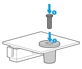
6. Install the removed PCIe modules. For more information, see "Installing riser cards and PCIe modules."
7. Install the access panel. For more information, see "Replacing the access panel."
8. Rack-mount the server. For more information, see "Rack-mounting the server."
9. Connect the power cord. For more information, see "Connecting the power cord."
10. Power on the server. For more information, see "Powering on the server."
Enabling the TCM or TPM in the BIOS
By default, the TCM and TPM are enabled for a server. For more information about configuring the TCM or TPM from the BIOS, see the BIOS user guide for the server.
You can log in to HDM to verify that the TCM or TPM is operating correctly. For more information, see HDM online help.
Configuring encryption in the operating system
For more information about this task, see the encryption technology feature documentation that came with the operating system.
The recovery key/password is generated during BitLocker setup, and can be saved and printed after BitLocker is enabled. When using BitLocker, always retain the recovery key/password. The recovery key/password is required to enter Recovery Mode after BitLocker detects a possible compromise of system integrity or firmware or hardware change.
For security purposes, follow these guidelines when retaining the recovery key/password:
· Always store the recovery key/password in multiple locations.
· Always store copies of the recovery key/password away from the server.
· Do not save the recovery key/password on the encrypted hard drive.
For more information about Microsoft Windows BitLocker drive encryption, visit the Microsoft website at http://technet.microsoft.com/en-us/library/cc732774.aspx.
Replacing hardware options
If you are replacing multiple hardware options, read their replacement procedures and identify similar steps to streamline the entire replacement procedure.
Replacing the access panel
|
|
WARNING! To avoid bodily injury from hot surfaces, allow the server and its internal modules to cool before touching them. |
|
|
CAUTION: To avoid thermal damage to the server, do not operate the server for long periods with the access panel open or uninstalled. |
If you are to replace a hot-swappable component in the chassis and sufficient space is available for replacement, you can replace the access panel without powering off the server or removing the server from the rack. The following procedure is provided based on the assumption that no sufficient space is available for replacement.
Removing the access panel
1. Power off the server. For more information, see "Powering off the server."
2. Remove the server from the rack. For more information, see "Removing the server from a rack."
3. Remove the access panel, as shown in Figure 122:
a. If the locking lever on the access panel is locked, unlock the locking lever. Use a T15 Torx screwdriver to turn the screw on the lever 90 degree anticlockwise, as shown by callout 1.
b. Press the latch on the locking lever, pull the locking lever upward, and then release the latch, as shown by callouts 2 and 3. The access panel will automatically slide to the rear of the server chassis.
c. Lift the access panel to remove it, as shown by callout 4.
Figure 122 Removing the access panel
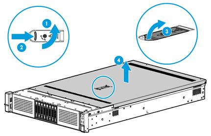
Installing the access panel
1. Press the latch on the locking lever and pull the locking lever upward, as shown in Figure 123.
If the locking lever on the access panel is locked, use a T15 Torx screwdriver to unlock the lever. For more information, see "Removing the access panel."
Figure 123 Opening the locking lever
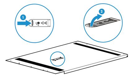
2. Install the access panel as shown in Figure 124:
a. Place the access panel on top of the server chassis, with the guide pin in the chassis aligned with the pin hole in the locking lever area, as shown by callout 1.
b. Close the locking lever, as shown by callout 2. The access panel will automatically slide toward the server front to secure itself into place.
c. (Optional.) Lock the locking lever. Use a T15 Torx screwdriver to turn the screw on the lever 90 degree clockwise, as shown by callout 3.
Figure 124 Installing the access panel
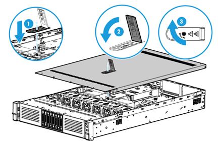
Replacing the security bezel
1. Insert the key provided with the bezel into the lock on the bezel and unlock the security bezel, as shown by callout 1 in Figure 125.
|
|
CAUTION: To avoid damage to the lock, hold down the key while you are turning the key. |
2. Press the latch at the left end of the bezel, open the security bezel, and then release the latch, as shown by callouts 2 and 3 in Figure 125.
3. Pull the right edge of the security bezel out of the groove in the right chassis ear to remove the security bezel, as shown by callout 4 in Figure 125.
Figure 125 Removing the security bezel
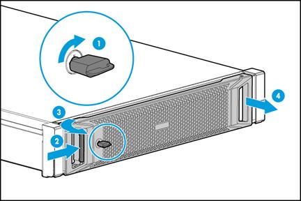
4. Install a new security bezel. For more information, see "Installing the security bezel."
Replacing a SAS/SATA drive
The drives are hot swappable.
To configure RAID settings after the drive is replaced, see the storage controller user guide for the server.
Prerequisites
To replace a drive in a non-redundancy RAID array with a drive of a different model, back up data in the RAID array.
Procedure
1. Remove the security bezel, if any. For more information, see "Replacing the security bezel."
2. Observe the drive LEDs to verify that the drive is not selected by the storage controller and is not performing a RAID migration or rebuilding. For more information about drive LEDs, see "Drive LEDs."
3. Remove the drive, as shown in Figure 126:
¡ To remove an SSD, press the button on the drive panel to release the locking lever, and then hold the locking lever and pull the drive out of the slot.
¡ To remove an HDD, press the button on the drive panel to release the locking lever. Pull the drive 3 cm (1.18 in) out of the slot. Wait for a minimum of 30 seconds for the drive to stop rotating, and then pull the drive out of the slot.
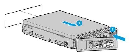
4. Install a new drive. For more information, see "Installing SAS/SATA drives."
5. Install the removed security bezel, if any. For more information, see "Installing the security bezel."
Verifying the replacement
Use one of the following methods to verify that the drive has been replaced correctly:
· Verify the drive properties (including capacity) by using one of the following methods:
¡ Log in to HDM. For more information, see HDM online help.
¡ Access BIOS. For more information, see the storage controller user guide for the server.
¡ Access the CLI or GUI of the server.
· Observe the drive LEDs to verify that the drive is operating correctly. For more information about drive LEDs, see "Drive LEDs."
Replacing an NVMe drive
The drives support hot insertion and managed hot removal.
To configure RAID settings after the drive is replaced, see the storage controller user guide for the server.
Only one drive can be hot inserted at a time. To hot insert multiple NVMe drives, wait a minimum of 60 seconds for the previously installed NVMe drive to be identified before hot inserting another NVMe drive.
Procedure
1. Identify the NVMe drive to be removed and perform managed hot removal for the drive. For more information about managed hot removal, see "Appendix D Managed hot removal of NVMe drives."
2. Remove the security bezel, if any. For more information, see "Replacing the security bezel."
3. Remove the drive:
a. Press the button on the drive panel to release the locking lever, as shown by callout 1 in Figure 127.
b. Hold the locking lever and pull the drive out of the slot, as shown by callout 2 in Figure 127.

4. Install a new drive. For more information, see "Installing SAS/SATA drives."
5. Install the removed security bezel, if any. For more information, see "Installing the security bezel."
Verifying the replacement
Use one of the following methods to verify that the drive has been replaced correctly:
· Verify the drive properties (including capacity) by using one of the following methods:
¡ Access HDM. For more information, see HDM online help.
¡ Access the BIOS. For more information, see the BIOS user guide for the server.
¡ Access the CLI or GUI of the server.
· Observe the drive LEDs to verify that the drive is operating correctly. For more information about drive LEDs, see "Drive LEDs."
Replacing a power supply
The power supplies are hot swappable.
If two power supplies are installed and sufficient space is available for replacement, you can replace a power supply without powering off or removing the server from the rack.
Procedure
1. Power off the server. For more information, see "Powering off the server."
2. Remove the server from the rack. For more information, see "Removing the server from a rack."
3. To remove the AC power cord from an AC power supply or a 240 V high-voltage DC power supply:
a. Press the tab to disengage the ratchet from the tie mount, slide the cable clamp outward, and then release the tab, as shown by callouts 1 and 2 in Figure 128.
b. Open the cable clamp and remove the power cord out of the clamp, as shown by callouts 3 and 4 in Figure 128.
c. Unplug the power cord, as shown by callout 5 in Figure 128.
Figure 128 Removing the power cord
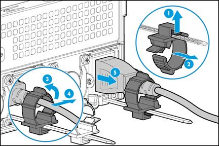
4. To remove the DC power cord from a –48 VDC power supply:
a. Loosen the captive screws on the power cord plug, as shown in Figure 129.
Figure 129 Loosening the captive screws
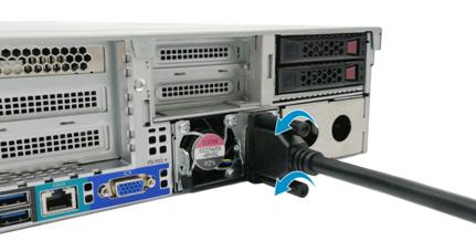
b. Pull the power cord plug out of the power receptacle, as shown in Figure 130.
Figure 130 Pulling out the DC power cord
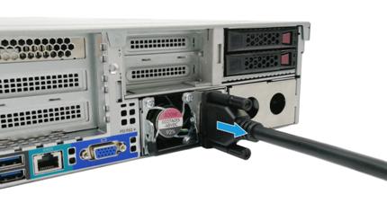
5. Holding the power supply by its handle and pressing the retaining latch with your thumb, pull the power supply slowly out of the slot, as shown in Figure 131.
Figure 131 Removing the power supply
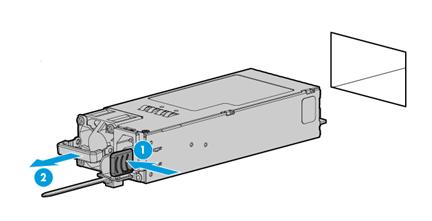
6. Install a new power supply. For more information, see "Installing power supplies."
|
|
IMPORTANT: If the server is configured with only one power supply, you must install the power supply in slot 2. |
7. Mount the server in the rack. For more information, see "Installing the server."
8. Connect the power cord. For more information, see "Connecting the power cord."
9. Power on the server. For more information, see "Powering on the server."
Verifying the replacement
Use the following methods to verify that the power supply has been replaced correctly:
· Observe the power supply LED to verify that the power supply LED is steady or flashing green. For more information about the power supply LED, see LEDs in "Rear panel."
· Log in to HDM to verify that the power supply status is correct. For more information, see HDM online help.
Replacing air baffles
|
|
WARNING! To avoid bodily injury from hot surfaces, allow the server and its internal modules to cool before touching them. |
Removing air baffles
1. Power off the server. For more information, see "Powering off the server."
2. Remove the server from the rack. For more information, see "Removing the server from a rack."
3. Remove the access panel. For more information, see "Replacing the access panel."
4. If you are to remove the chassis air baffle, remove the riser cards attached to the air baffle. To remove the GPU-dedicated chassis air baffle, you also need to remove the GPU-P100, GPU-V100, or GPU-V100-32G module.
For more information about removing a riser card and a GPU module, see "Replacing a riser card and a PCIe module" and "Replacing a GPU module."
5. Remove air baffles:
¡ To remove the chassis air baffle, hold the air baffle by the notches at both ends, and lift the air baffle out of the chassis, as shown in Figure 132.
The removal procedure is the same for the standard chassis air baffle and GPU-dedicated chassis air baffle. The following figure uses the standard chassis air baffle for illustration.
Figure 132 Removing the standard chassis air baffle
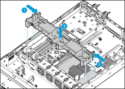
¡ To remove the power supply air baffle, pull outward the two clips that secure the air baffle, and lift the air baffle out of the chassis, as shown in Figure 133.
Figure 133 Removing the power supply air baffle
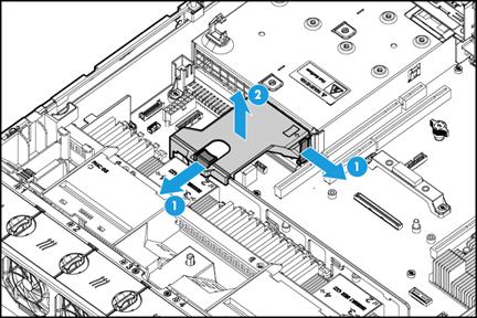
Installing air baffles
1. Install air baffles:
¡ To install the chassis air baffle, place the air baffle on top of the chassis, with the standouts at both ends of the air baffle aligned with the notches on the chassis edges, as shown in Figure 134.
The installation procedure is the same for the standard chassis air baffle and the GPU-dedicated chassis air baffle. The following figure uses the standard chassis air baffle for illustration.
Figure 134 Installing the standard chassis air baffle
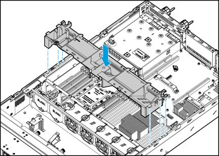
¡ To install the power supply air baffle, place the air baffle in the chassis as shown in Figure 135. Make sure the groove in the air baffle is aligned with the system board handle, and the extended narrow side indicated by the arrow mark makes close contact with the clip on the system board. Then gently press the air baffle until it snaps into place.
Figure 135 Removing the power supply air baffle
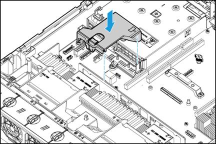
2. Install the removed riser card and GPU module, if any. For more information, see "Replacing a riser card and a PCIe module."
3. Install the access panel. For more information, see "Replacing the access panel."
4. Mount the server in a rack. For more information, see "Installing the server."
5. Connect the power cord. For more information, see "Connecting the power cord."
6. Power on the server. For more information, see "Powering on the server."
Replacing a riser card and a PCIe module
|
|
WARNING! To avoid bodily injury from hot surfaces, allow the server and its internal modules to cool before touching them. |
To replace a riser card and a PCIe module:
1. Power off the server. For more information, see "Powering off the server."
2. Remove the server from the rack. For more information, see "Removing the server from a rack."
3. Remove the access panel. For more information, see "Replacing the access panel."
4. Disconnect all PCIe cables from the riser card.
5. Loosen the captive screw on the riser card, and lift the riser card slowly out of the chassis, as shown in Figure 136.
Skip this step if the riser card does not have a captive screw. This example uses the RC-GPU/FHHL-2U-G3-2 riser card, which has a captive screw.
Figure 136 Removing the RC-GPU/FHHL-2U-G3-2 riser card
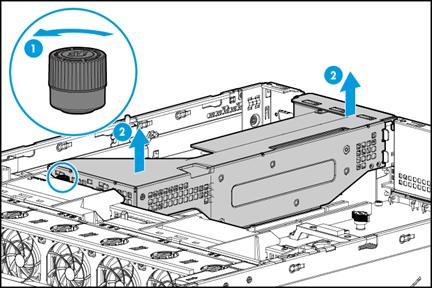
6. Remove the screw that secures the PCIe module, and then pull the PCIe module out of the slot, as shown in Figure 137.
Figure 137 Removing a PCIe module
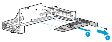
7. Install a new riser card and PCIe module. For more information, see "Installing riser cards and PCIe modules."
8. Install the access panel. For more information, see "Replacing the access panel."
9. Mount the server in the rack. For more information, see "Installing the server."
10. Connect the power cord. For more information, see "Connecting the power cord."
11. Power on the server. For more information, see "Powering on the server."
Replacing an RC-Mezz-Riser-G3 Mezz PCIe riser card
|
|
WARNING! To avoid bodily injury from hot surfaces, allow the server and its internal modules to cool before touching them. |
To replace the RC-Mezz-Riser-G3 Mezz PCIe riser card:
1. Power off the server. For more information, see "Powering off the server."
2. Remove the server from the rack. For more information, see "Removing the server from a rack."
3. Remove the access panel. For more information, see "Replacing the access panel."
4. Remove the RC-2*FHFL-2U-G3 riser card. For more information, see "Replacing a riser card and a PCIe module."
5. Disconnect PCIe signal cables from the RC-Mezz-Riser-G3 Mezz PCIe riser card.
Figure 138 Disconnecting PCIe signal cables from the RC-Mezz-Riser-G3 Mezz PCIe riser card
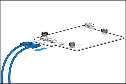
6. Loosen the captive screw on the module, and pull the module out of the chassis, as shown in Figure 139.
Figure 139 Removing the RC-Mezz-Riser-G3 Mezz PCIe riser card
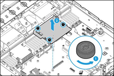
7. Install a new RC-Mezz-Riser-G3 Mezz PCIe riser card and the RC-2*FHFL-2U-G3 riser card. For more information, see "Installing riser cards and PCIe modules."
8. Install the access panel. For more information, see "Replacing the access panel."
9. Rack-mount the server. For more information, see "Installing the server."
10. Connect the power cord. For more information, see "Connecting the power cord."
11. Power on the server. For more information, see "Powering on the server."
Replacing a storage controller
|
|
WARNING! To avoid bodily injury from hot surfaces, allow the server and its internal modules to cool before touching them. |
Guidelines
To replace the storage controller with a controller of a different model, reconfigure RAID after the replacement. For more information, see the storage controller user guide for the server.
To replace the storage controller with a controller of the same model, make sure the following configurations remain the same after replacement:
· Storage controller operating mode.
· Storage controller firmware version.
· BIOS boot mode.
· First boot option in Legacy mode.
For more information, see the storage controller user guide for the server and the BIOS user guide for the server.
Preparing for replacement
To replace the storage controller with a controller of the same model, identify the following information before the replacement:
· Storage controller location and cabling.
· Storage controller model, operating mode, and firmware version.
· BIOS boot mode.
· First boot option in Legacy mode.
To replace the storage controller with a controller of a different model, back up data in drives and then clear RAID information before the replacement.
Replacing the Mezzanine storage controller
Procedure
1. Power off the server. For more information, see "Powering off the server."
2. Remove the server from the rack. For more information, see "Removing the server from a rack."
3. Remove the access panel. For more information, see "Replacing the access panel."
4. Remove the air baffles as needed. For more information, see "Removing air baffles."
5. Remove the fan cage. For more information, see "Replacing the fan cage."
6. For the ease of replacement, remove the riser cards installed on PCIe riser connectors 1 and 2, if any. For more information, see "Replacing a riser card and a PCIe module."
7. Disconnect all cables from the Mezzanine storage controller.
8. Loosen the captive screws on the Mezzanine storage controller, and then lift the storage controller to remove it, as shown in Figure 140.
Figure 140 Removing the Mezzanine storage controller
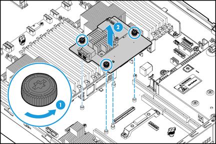
9. (Optional.) Remove the power fail safeguard module and install a new module. For more information, see "Replacing the power fail safeguard module for the Mezzanine storage controller."
10. Install a new Mezzanine storage controller. For more information, see "Installing a Mezzanine storage controller and a power fail safeguard module."
11. Install the removed riser cards. For more information, see "Installing riser cards and PCIe modules."
12. Install the removed fan cage. For more information, see "Installing fans."
13. Install the removed air baffles. For more information, see "Installing air baffles."
14. Install the access panel. For more information, see "Replacing the access panel."
15. Rack-mount the server. For more information, see "Rack-mounting the server."
16. Connect the power cord. For more information, see "Connecting the power cord."
17. Power on the server. For more information, see "Powering on the server."
Verifying the replacement
Log in to HDM to verify that the Mezzanine storage controller is in a correct state. For more information, see HDM online help.
Replacing a standard storage controller
Procedure
1. Power off the server. For more information, see "Powering off the server."
2. Remove the server from the rack. For more information, see "Removing the server from a rack."
3. Remove the access panel. For more information, see "Replacing the access panel."
4. Remove the air baffles as needed. For more information, see "Removing air baffles."
5. Remove the fan cage. For more information, see "Replacing the fan cage."
6. Disconnect all cables from the standard storage controller.
7. Remove the standard storage controller. For more information, see "Replacing a standard storage controller."
8. Remove the flash card on the standard storage controller, if any. If you are to install a new power fail safeguard module, remove the flash card, supercapacitor, and supercapacitor holder for the removed Mezzanine storage controller. For more information, see "Replacing the power fail safeguard module for a standard storage controller."
9. Install a new standard storage controller and the removed flash card. For more information, see "Installing a standard storage controller and a power fail safeguard module."
10. Install the removed fan cage. For more information, see "Installing fans."
11. Install the removed air baffles. For more information, see "Installing air baffles."
12. Install the access panel. For more information, see "Replacing the access panel."
13. Rack-mount the server. For more information, see "Rack-mounting the server."
14. Connect the power cord. For more information, see "Connecting the power cord."
15. Power on the server. For more information, see "Powering on the server."
Verifying the replacement
Log in to HDM to verify that the standard storage controller is in a correct state. For more information, see HDM online help.
Replacing the power fail safeguard module
|
|
WARNING! To avoid bodily injury from hot surfaces, allow the server and its internal modules to cool before touching them. |
Replacing the power fail safeguard module for the Mezzanine storage controller
|
|
CAUTION: To avoid server errors, do not replace the power fail safeguard module when a drive is performing RAID migration or rebuilding. The Fault/UID LED is off and the Present/Active LED is flashing green on a drive if the drive is performing migration or rebuilding. |
Procedure
1. Power off the server. For more information, see "Powering off the server."
2. Remove the server from the rack. For more information, see "Removing the server from a rack."
3. Remove the access panel. For more information, see "Replacing the access panel."
4. Remove the air baffles as needed. For more information, see "Removing air baffles."
5. Remove the fan cage. For more information, see "Replacing the fan cage."
6. Disconnect cables that might hinder the replacement.
7. Remove the flash card on the storage controller, if any. Remove the screws that secure the flash card, and then remove the flash card, as shown in Figure 141.
Figure 141 Removing the flash card on the Mezzanine storage controller
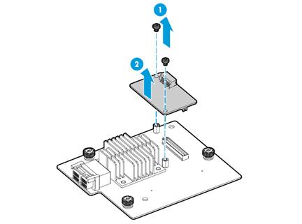
8. Remove cables from the front drive backplanes if they hinder access to the supercapacitor.
9. Remove the supercapacitor:
¡ To remove the supercapacitor in the server chassis, pull the clip on the supercapacitor holder, take the supercapacitor out of the holder, and then release the clip, as shown in Figure 142. Then, lift the retaining latch at the bottom of the supercapacitor holder, slide the holder to remove it, and then release the retaining latch, as shown in Figure 143.
Figure 142 Removing the supercapacitor
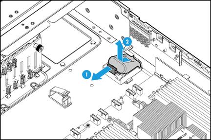
Figure 143 Removing the supercapacitor holder
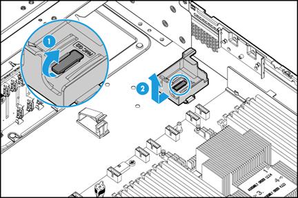
¡ To remove the supercapacitor on the air baffle, pull the clip on the supercapacitor holder, take the supercapacitor out of the holder, and then release the clip, as shown in Figure 142.
¡ To remove the supercapacitor in the supercapacitor container, remove the screw that secures the supercapacitor container, and then pull the cage out of the slot, as shown in Figure 144. Then, open the cable clamp and take the supercapacitor out of the cage, as shown in Figure 145.
Figure 144 Removing the supercapacitor container
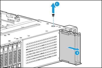
Figure 145 Removing the supercapacitor
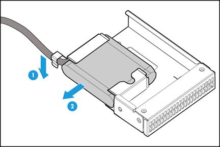
10. Install a new power fail safeguard module. For more information, see "Installing a Mezzanine storage controller and a power fail safeguard module."
11. Reconnect the removed cables to the front drives backplane. For more information, see "8SFF server."
12. Install the removed fan cage. For more information, see "Installing fans."
13. Install the removed air baffles. For more information, see "Installing air baffles."
14. Install the access panel. For more information, see "Replacing the access panel."
15. Rack-mount the server. For more information, see "Rack-mounting the server."
16. Connect the power cord. For more information, see "Connecting the power cord."
17. Power on the server. For more information, see "Powering on the server."
Verifying the replacement
Log in to HDM to verify that the flash card and the supercapacitor are in a correct state. For more information, see HDM online help.
Replacing the power fail safeguard module for a standard storage controller
|
|
CAUTION: To avoid server errors, do not replace the power fail safeguard module when a drive is performing RAID migration or rebuilding. The Fault/UID LED is off and the Present/Active LED is flashing green on a drive if the drive is performing migration or rebuilding. |
Procedure
1. Power off the server. For more information, see "Powering off the server."
2. Remove the server from the rack. For more information, see "Removing the server from a rack."
3. Remove the access panel. For more information, see "Replacing the access panel."
4. Remove the air baffles as needed. For more information, see "Removing air baffles."
5. Remove the fan cage. For more information, see "Replacing the fan cage."
6. Disconnect cables that might hinder the replacement.
7. Remove the standard storage controller. For more information, see "Replacing a standard storage controller."
8. Remove the flash card on the storage controller, if any. Remove the screws that secure the flash card, and then remove the flash card.
Figure 146 Removing the flash card on a standard storage controller
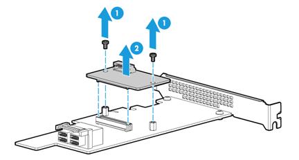
9. Remove the supercapacitor. For more information, see "Replacing the power fail safeguard module for the Mezzanine storage controller."
10. Install a new power fail safeguard module. For more information, see "Installing a standard storage controller and a power fail safeguard module."
11. Install the removed fan cage. For more information, see "Installing fans."
12. Install the removed air baffles. For more information, see "Installing air baffles."
13. Install the access panel. For more information, see "Replacing the access panel."
14. Rack-mount the server. For more information, see "Rack-mounting the server."
15. Connect the power cord. For more information, see "Connecting the power cord."
16. Power on the server. For more information, see "Powering on the server."
Verifying the replacement
Log in to HDM to verify that the flash card and the supercapacitor are in a correct state. For more information, see HDM online help.
Replacing a GPU module
|
|
WARNING! To avoid bodily injury from hot surfaces, allow the server and its internal modules to cool before touching them. |
Replacing a GPU module without a power cord or with a standard chassis air baffle
1. Power off the server. For more information, see "Powering off the server."
2. Remove the server from the rack. For more information, see "Removing the server from a rack."
3. Remove the access panel. For more information, see "Replacing the access panel."
4. Loosen the captive screw on the riser card that contains the GPU module, and remove the riser card from the chassis, as shown in Figure 147.
Figure 147 Removing the riser card that contains the GPU module
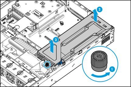
5. Remove the GPU module:
a. Remove the screw that secures the GPU module, as shown by callout 1 in Figure 148.
b. Disconnect the power cord from the riser card, as shown by callout 2 in Figure 148.
c. Pull the GPU module out of the PCIe slot, and then remove the power cord of the GPU module (if any), as shown by callouts 3 and 4 in Figure 148.
This example uses GPU-M4000-1-X GPU module in PCIe slot 1 to show the procedure. Not all GPU modules have power cords.
Figure 148 Removing the GPU module from the riser card
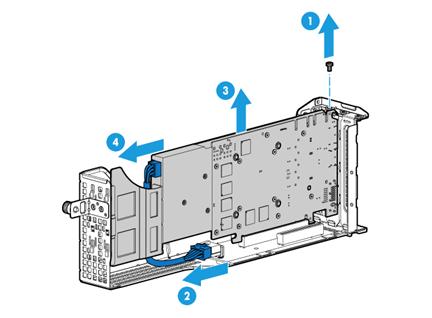
6. Install a new GPU module. For more information, see "Installing GPU modules."
7. Install the access panel. For more information, see "Replacing the access panel."
8. Rack-mount the server. For more information, see "Rack-mounting the server."
9. Connect the power cord. For more information, see "Connecting the power cord."
10. Power on the server. For more information, see "Powering on the server."
Verifying the installation
Log in to HDM to verify that the GPU module is operating correctly. For more information, see HDM online help.
Replacing a GPU module with a power cord and a GPU-dedicated chassis air baffle
The replacement procedure is the same for the GPU-V100-32G, GPU-V100, and GPU-P100 modules. This section replaces the GPU-P100.
To replace a GPU module with a power cord and a GPU-dedicated chassis air baffle:
1. Power off the server. For more information, see "Powering off the server."
2. Remove the server from the rack. For more information, see "Removing the server from a rack."
3. Remove the access panel. For more information, see "Replacing the access panel."
4. Remove the screw on the riser card that that has a GPU module attached, and remove the riser card from the chassis, as shown in Figure 149.
Figure 149 Removing the riser card that has a GPU module attached
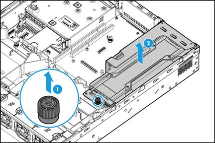
5. Remove the GPU module. For more information, see "Replacing a GPU module without a power cord or with a standard chassis air baffle."
6. Remove the screws that attach the support bracket to the GPU module, and remove the support bracket, as shown in Figure 150.
Figure 150 Removing the GPU module support bracket
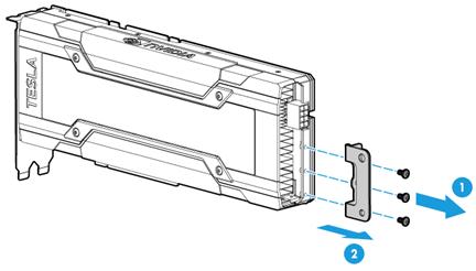
7. Install a new GPU module. For more information, see "Installing GPU modules."
8. Install the access panel. For more information, see "Replacing the access panel."
9. Rack-mount the server. For more information, see "Rack-mounting the server."
10. Connect the power cord. For more information, see "Connecting the power cord."
11. Power on the server. For more information, see "Powering on the server."
Verifying the installation
Log in to HDM to verify that the GPU module is operating correctly. For more information, see HDM online help.
Replacing an Ethernet adapter
Replacing an mLOM Ethernet adapter
Procedure
1. Power off the server. For more information, see "Powering off the server."
2. Disconnect cables from the Ethernet adapter.
3. Loosen the captive screws and then pull the Ethernet adapter out of the slot, as shown in Figure 151.
Some mLOM Ethernet adapters have only one captive screw. This example uses an Ethernet adapter with two screws.
Figure 151 Removing an mLOM Ethernet adapter
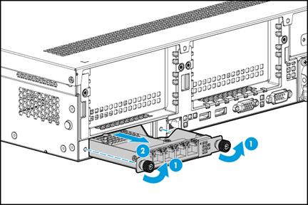
4. Install a new mLOM Ethernet adapter. For more information, see "Installing an mLOM Ethernet adapter."
5. Connect cables for the mLOM Ethernet adapter.
6. Power on the server. For more information, see "Powering on the server."
Verifying the replacement
Log in to HDM to verify that the mLOM Ethernet adapter is in a correct state. For more information, see HDM online help.
Replacing a PCIe Ethernet adapter
|
|
WARNING! To avoid bodily injury from hot surfaces, allow the server and its internal modules to cool before touching them. |
Procedure
1. Power off the server. For more information, see "Powering off the server."
2. Remove the server from the rack. For more information, see "Removing the server from a rack."
3. Remove the access panel. For more information, see "Replacing the access panel."
4. Disconnect cables from the PCIe Ethernet adapter.
5. Remove the PCIe Ethernet adapter. For more information, see "Replacing a riser card and a PCIe module."
6. Install a new PCIe Ethernet adapter. For more information, see "Installing riser cards and PCIe modules."
7. Connect cables for the PCIe Ethernet adapter.
8. Install the access panel. For more information, see "Replacing the access panel."
9. Rack-mount the server. For more information, see "Rack-mounting the server."
10. Connect the power cord. For more information, see "Connecting the power cord."
11. Power on the server. For more information, see "Powering on the server."
Verifying the replacement
Log in to HDM to verify that the PCIe Ethernet adapter is in a correct state. For more information, see HDM online help.
Replacing a M.2 transfer module and a SATA M.2 SSD
|
|
WARNING! To avoid bodily injury from hot surfaces, allow the server and its internal modules to cool before touching them. |
Replacing the front M.2 transfer module and a SATA M.2 SSD
1. Power off the server. For more information, see "Powering off the server."
2. Remove the server from the rack. For more information, see "Removing the server from a rack."
3. Remove the access panel. For more information, see "Replacing the access panel."
4. Remove the chassis air baffle. For more information, see "Removing air baffles."
5. Remove the fan cage. For more information, see "Replacing the fan cage."
6. Remove the security bezel, if any. For more information, see "Replacing the security bezel."
7. Remove the SATA M.2 SSD:
a. Remove the M.2 transfer module. To remove the module, disconnect the cable connected to the M.2 transfer module. Then remove the M.2 transfer module in the same way as removing a SATA optical drive. For more information, see "Replacing the SATA optical drive."
b. Remove the screw that secures the SSD on the transfer module. Tilt the SSD by the screw-side edges, and then pull the SSD out of the connector, as shown in Figure 152.
Figure 152 Removing a SATA M.2 SSD
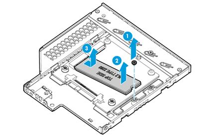
8. Install a new SATA M.2 SSD. For more information, see "Installing SATA M.2 SSDs."
9. Install the removed security bezel, if any. For more information, see "Installing the security bezel."
10. Install the removed fan cage. For more information, see "Installing fans."
11. Install the removed chassis air baffle. For more information, see "Installing air baffles."
12. Install the access panel. For more information, see "Replacing the access panel."
13. Rack-mount the server. For more information, see "Rack-mounting the server."
14. Connect the power cord. For more information, see "Connecting the power cord."
15. Power on the server. For more information, see "Powering on the server."
Replacing the rear M.2 transfer module and a SATA M.2 SSD
1. Power off the server. For more information, see "Powering off the server."
2. Remove the server from the rack. For more information, see "Removing the server from a rack."
3. Remove the access panel. For more information, see "Replacing the access panel."
4. Disconnect the SATA M.2 SSD cable from the system board. For more information, see "Connecting the SATA M.2 SSD cable."
5. Remove the riser card that has a M.2 transfer module attached. For more information, see "Replacing a riser card and a PCIe module."
6. Remove the M.2 transfer module from the riser card. For more information, see "Replacing a riser card and a PCIe module."
7. Remove the SATA M.2 SSD:
a. Disconnect the SATA M.2 SSD cable from the M.2 transfer module, as shown by callout 1 in Figure 153.
b. Remove the screw that secures the SSD on the expander module. Tilt the SSD by the screw-side edges, and then pull the SSD out of the connector, as shown in Figure 153.
Figure 153 Removing a SATA M.2 SSD
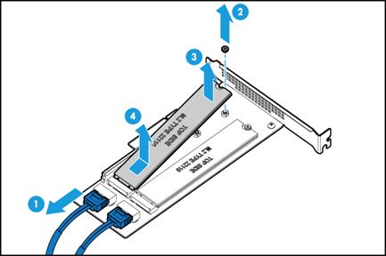
8. Install a new rear M.2 transfer module and SATA M.2 SSDs. For more information, see "Installing SATA M.2 SSDs at the server rear."
9. Install the access panel. For more information, see "Replacing the access panel."
10. Rack-mount the server. For more information, see "Rack-mounting the server."
11. Connect the power cord. For more information, see "Connecting the power cord."
12. Power on the server. For more information, see "Powering on the server."
Replacing an SD card
|
|
WARNING! To avoid bodily injury from hot surfaces, allow the server and its internal modules to cool before touching them. |
|
|
CAUTION: To avoid thermal damage to the server, do not operate the server for long periods with the access panel open or uninstalled. |
The SD cards are hot swappable. If sufficient space is available for replacement, you can replace an SD card without powering off the server or removing the server from the rack. The following procedure is provided based on the assumption that no sufficient space is available for replacement.
To replace an SD card:
1. Power off the server. For more information, see "Powering off the server."
2. Remove the server from the rack. For more information, see "Removing the server from a rack."
3. Remove the access panel. For more information, see "Replacing the access panel."
4. For the ease of replacement, remove the PCIe riser card installed on PCIe riser connector 3, if any. For more information, see "Replacing a riser card and a PCIe module."
5. Press the SD card to release it and then pull the SD card out of the slot, as shown in Figure 154.
Figure 154 Removing an SD card
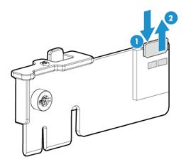
6. Install a new SD card. For more information, see "Installing SD cards."
7. Install the removed PCIe riser card on PCIe riser connector 3. For more information, see "Installing riser cards and PCIe modules."
8. Install the access panel. For more information, see "Replacing the access panel."
9. Rack-mount the server. For more information, see "Rack-mounting the server."
10. Connect the power cord. For more information, see "Connecting the power cord."
11. Power on the server. For more information, see "Powering on the server."
Replacing the dual SD card extended module
|
|
WARNING! To avoid bodily injury from hot surfaces, allow the server and its internal modules to cool before touching them. |
To replace the dual SD card extended module:
1. Power off the server. For more information, see "Powering off the server."
2. Remove the server from the rack. For more information, see "Removing the server from a rack."
3. Remove the access panel. For more information, see "Replacing the access panel."
4. For the ease of replacement, remove the PCIe riser card installed on PCIe riser connector 3, if any. For more information, see "Replacing a riser card and a PCIe module."
5. Press the blue clip on the dual SD card extended module, as shown by callout 1 in Figure 155. Pull the module out of the connector, and then release the clip.
Figure 155 Removing the dual SD card extended module
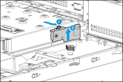
6. Remove the SD cards installed on the extended module, as shown in Figure 154.
7. Install a new dual SD card extended module and the removed SD cards. For more information, see "Installing SD cards."
8. Install the removed PCIe riser card on PCIe riser connector 3. For more information, see "Installing riser cards and PCIe modules."
9. Install the access panel. For more information, see "Replacing the access panel."
10. Rack-mount the server. For more information, see "Rack-mounting the server."
11. Connect the power cord. For more information, see "Connecting the power cord."
12. Power on the server. For more information, see "Powering on the server."
Replacing an NVMe SSD expander module
|
|
WARNING! To avoid bodily injury from hot surfaces, allow the server and its internal modules to cool before touching them. |
Procedure
1. Power off the server. For more information, see "Powering off the server."
2. Remove the server from the rack. For more information, see "Removing the server from a rack."
3. Remove the access panel. For more information, see "Replacing the access panel."
4. Remove the chassis air baffle. For more information, see "Removing air baffles."
5. Remove the fan cage. For more information, see "Replacing the fan cage."
6. Remove the NVMe SSD expander module:
a. Disconnect the expander module from the front drive backplanes by removing the cables from the front drive backplanes.
b. Remove the PCIe riser card that contains the NVMe SSD expander module. For more information, see "Replacing a riser card and a PCIe module."
c. Disconnect cables from the NVMe SSD expander modules, as shown in Figure 156.
Figure 156 Disconnecting cables from an NVMe SSD expander module
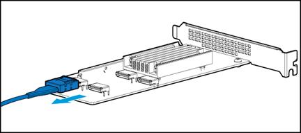
7. Install a new NVMe SSD expander module. For more information, see "Installing an NVMe SSD expander module."
8. Install the removed fan cage. For more information, see "Installing fans."
9. Install the removed chassis air baffle. For more information, see "Installing air baffles."
10. Install the access panel. For more information, see "Replacing the access panel."
11. Rack-mount the server. For more information, see "Rack-mounting the server."
12. Power on the server. For more information, see "Powering on the server."
Verifying the replacement
Log in to HDM to verify that the NVMe expander module is in a correct state. For more information, see HDM online help.
Replacing an NVMe VROC module
|
|
WARNING! To avoid bodily injury from hot surfaces, allow the server and its internal modules to cool before touching them. |
To remove the NVMe VROC module:
1. Power off the server. For more information, see "Powering off the server."
2. Remove the server from the rack. For more information, see "Removing the server from a rack."
3. Remove the access panel. For more information, see "Replacing the access panel."
4. Remove the power supply air baffle. For more information, see "Removing air baffles."
5. Hold the ring part of the NVMe VROC module and pull the module out of the chassis, as shown in Figure 157.
Figure 157 Removing the NVMe VROC module
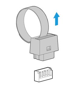
6. Install a new NVMe VROC module. For more information, see "Installing the NVMe VROC module."
7. Install the removed power supply air baffle. For more information, see "Installing air baffles."
8. Install the access panel. For more information, see "Replacing the access panel."
9. Rack-mount the server. For more information, see "Rack-mounting the server."
10. Power on the server. For more information, see "Powering on the server."
Replacing a fan
|
|
WARNING! To avoid bodily injury from hot surfaces, allow the server and its internal modules to cool before touching them. |
|
|
CAUTION: To avoid thermal damage to the server, do not operate the server for long periods with the access panel open or uninstalled. |
The fans are hot swappable. If sufficient space is available for replacement, you can replace a fan without powering off the server or removing the server from the rack. The following procedure is provided based on the assumption that no sufficient space is available for replacement.
Procedure
1. Power off the server. For more information, see "Powering off the server."
2. Remove the server from the rack. For more information, see "Removing the server from a rack."
3. Remove the access panel. For more information, see "Replacing the access panel."
4. Pinch the latches on both sides of the fan to pull the fan out of the slot, as shown in Figure 158.
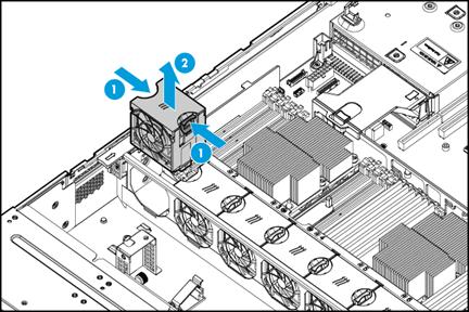
5. Install a new fan. For more information, see "Installing fans."
6. Install the access panel. For more information, see "Replacing the access panel."
7. Rack-mount the server. For more information, see "Rack-mounting the server."
8. Connect the power cord. For more information, see "Connecting the power cord."
9. Power on the server. For more information, see "Powering on the server."
Verifying the replacement
Log in to HDM to verify that the fan is in a correct state. For more information, see HDM online help.
Replacing the fan cage
|
|
WARNING! To avoid bodily injury from hot surfaces, allow the server and its internal modules to cool before touching them. |
To replace the fan cage:
1. Power off the server. For more information, see "Powering off the server."
2. Remove the server from the rack. For more information, see "Removing the server from a rack."
3. Remove the access panel. For more information, see "Replacing the access panel."
4. Remove the chassis air baffle. For more information, see "Removing air baffles."
5. Remove the fan cage:
a. Open the locking levers at the two ends of the fan cage, as shown by callout 1 in Figure 159.
b. Lift the fan cage out of the chassis, as shown by callout 2 in Figure 159.
Figure 159 Removing a fan cage
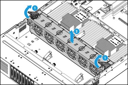
6. Install a new fan cage. For more information, see "Installing fans."
7. Install the chassis air baffle. For more information, see "Installing air baffles."
8. Install the access panel. For more information, see "Replacing the access panel."
9. Rack-mount the server. For more information, see "Rack-mounting the server."
10. Power on the server. For more information, see "Powering on the server."
Replacing a DIMM
|
|
WARNING! To avoid bodily injury from hot surfaces, allow the server and its internal modules to cool before touching them. |
Procedure
1. Power off the server. For more information, see "Powering off the server."
2. Remove the server from the rack. For more information, see "Removing the server from a rack."
3. Remove the access panel. For more information, see "Replacing the access panel."
4. Remove the chassis air baffle. For more information, see "Removing air baffles."
5. Open the DIMM slot latches and pull the DIMM out of the slot, as shown in Figure 160.
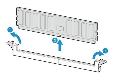
6. Install a new DIMM. For more information, see "Installing DIMMs."
7. Install the chassis air baffle. For more information, see "Installing air baffles."
8. Install the access panel. For more information, see "Replacing the access panel."
9. Rack-mount the server. For more information, see "Rack-mounting the server."
10. Connect the power cord. For more information, see "Connecting the power cord."
11. Power on the server. For more information, see "Powering on the server."
During server startup, you can access BIOS to configure the memory mode of the newly installed DIMM. For more information, see the BIOS user guide for the server.
Verifying the replacement
Use one of the following methods to verify that the memory size is correct:
· Access the GUI or CLI of the server:
¡ In the GUI of a windows OS, click the Start icon in the bottom left corner, enter msinfo32 in the search box, and then click the msinfo32 item.
¡ In the CLI of a Linux OS, execute the cat /proc/meminfo command.
· Log in to HDM. For more information, see HDM online help.
· Access BIOS. For more information, see the BIOS user guide for the server.
If the memory size is incorrect, re-install or replace the DIMM.
|
|
NOTE: It is normal that the CLI or GUI of the server OS displays a smaller memory size than the actual size if the mirror, partial mirror, or memory rank sparing memory mode is enabled. In this situation, you can verify the memory size from HDM or BIOS. |
Replacing a processor
|
|
WARNING! To avoid bodily injury from hot surfaces, allow the server and its internal modules to cool before touching them. |
Guidelines
· To avoid damage to a processor or the system board, only H3C authorized or professional server engineers can install, replace, or remove a processor.
· Make sure the processors on the server are the same model.
· The pins in the processor sockets are very fragile and prone to damage. Install a protective cover if a processor socket is empty.
· For the server to operate correctly, make sure processor 1 is in position. For more information about processor locations, see "System board components."
Prerequisites
To avoid ESD damage, wear an ESD wrist strap before performing this task, and make sure the wrist strap is reliably grounded.
Removing a processor
1. Power off the server. For more information, see "Powering off the server."
2. Remove the server from the rack. For more information, see "Removing the server from a rack."
3. Remove the access panel. For more information, see "Replacing the access panel."
4. Remove the chassis air baffle. For more information, see "Removing air baffles."
5. Remove the processor heatsink:
a. Loosen the captive screws in the same sequence as shown by callouts 1 to 4 in Figure 161.
b. Lift the heatsink slowly to remove it, as shown by callout 5 in Figure 161.
Figure 161 Removing a processor heatsink
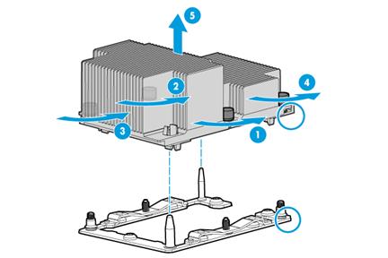
6. Remove the processor retaining bracket from the heatsink:
a. Insert a flat-head tool (such as a flat-head screwdriver) into the notch marked with TIM BREAKER to pry open the retaining bracket, as shown by callout 1 in Figure 162.
b. Press the four clips in the four corners of the bracket to release the retaining bracket.
You must press the clip shown by callout 2 in Figure 167 and its cater-cornered clip outward, and press the other two clips inward as shown by callout 3 in Figure 167.
c. Lift the retaining bracket to remove it from the heatsink, as shown by callout 4 in Figure 162.
Figure 162 Removing the processor retaining bracket
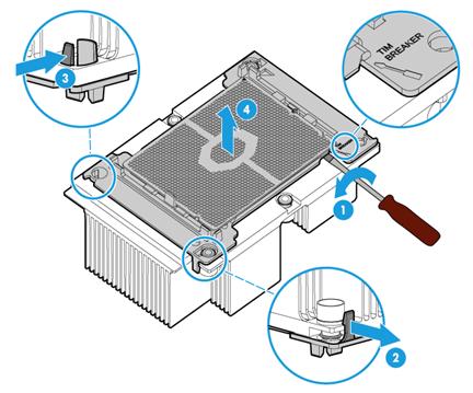
7. Separate the processor from the retaining bracket with one hand pushing down and the other hand tilting the processor, as shown in Figure 163.
Figure 163 Separating the processor from the retaining bracket
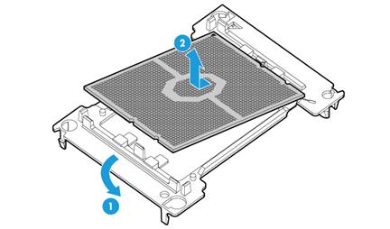
Installing a processor
1. Install the processor onto the retaining bracket. For more information, see "Installing processors."
2. Smear thermal grease onto the processor:
a. Clean the processor and heatsink with isopropanol wipes. Allow the isopropanol to evaporate before continuing.
b. Use the thermal grease injector to inject 0.6 ml of thermal grease to the five dots on the processor, 0.12 ml for each dot, as shown in Figure 164.
Figure 164 Smearing thermal grease onto the processor
3. Install the retaining bracket onto the heatsink. For more information, see "Installing processors."
4. Install the heatsink onto the server. For more information, see "Installing processors."
5. Past bar code label supplied with the processor over the original processor label on the heatsink.
|
|
IMPORTANT: This step is required for you to obtain H3C's processor servicing. |
6. (Optional.) Remove or install the chassis air baffle panels:
¡ Remove the air baffle panels if you are replacing a standard-performance heatsink (without copper pipes) with a high-performance heatsink (with copper pipes). To remove the air baffle panels, lift the clips that secure the panels, and slide the panels outward to remove them, as shown in Figure 165.
Figure 165 Removing air baffle panels
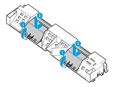
¡ Install the air baffle panels if you are replacing a high-performance heatsink (with copper pipes) with a standard-performance heatsink (without copper pipes). To install the air baffle panels, place the panels in the slots, and then push the panels into the slot until they snap into place, as shown in Figure 166.
Figure 166 Installing air baffle panels
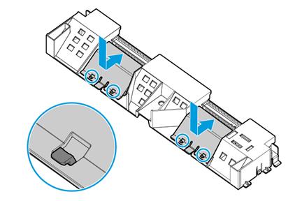
7. Install the chassis air baffle. For more information, see "Installing air baffles."
8. Install the access panel. For more information, see "Replacing the access panel."
9. Rack-mount the server. For more information, see "Rack-mounting the server."
10. Connect the power cord. For more information, see "Connecting the power cord."
11. Power on the server. For more information, see "Powering on the server."
Replacing the system battery
|
|
WARNING! To avoid bodily injury from hot surfaces, allow the server and its internal modules to cool before touching them. |
The server comes with a system battery (Panasonic BR2032) installed on the system board, which supplies power to the real-time clock and has a lifespan of 5 to 10 years. If the server no longer automatically displays the correct date and time, you might need to replace the battery. As a best practice, use a new Panasonic BR2032 battery to replace the old one.
|
|
NOTE: The BIOS will restore to the default settings after the replacement. You must reconfigure the BIOS to have the desired settings, including the system date and time. For more information, see the BIOS user guide for the server. |
Removing the system battery
1. Power off the server. For more information, see "Powering off the server."
2. Remove the server from the rack. For more information, see "Removing the server from a rack."
3. Remove the access panel. For more information, see "Replacing the access panel."
4. (Optional.) Remove PCIe modules that might hinder system battery removal. For more information, see "Replacing a riser card and a PCIe module."
5. Gently tilt the system battery to remove it from the battery holder, as shown in Figure 167.
Figure 167 Removing the system battery
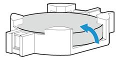
|
|
NOTE: For environment protection purposes, dispose of the used-up system battery at a designated site. |
Installing the system battery
1. Orient the system battery with the plus-sign (+) side facing up, and place the system battery into the system battery holder, as shown by callout 1 in Figure 168.
2. Press the system battery to seat it in the holder, as shown by callout 2 in Figure 168.
Figure 168 Installing the system battery
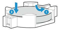
3. (Optional.) Install the removed PCIe modules. For more information, see "Installing riser cards and PCIe modules."
4. Install the access panel. For more information, see "Replacing the access panel."
5. Rack-mount the server. For more information, see "Rack-mounting the server."
6. Connect the power cord. For more information, see "Connecting the power cord."
7. Power on the server. For more information, see "Powering on the server."
8. Access the BIOS to reconfigure the system date and time. For more information, see the BIOS user guide for the server.
Verifying the replacement
Verify that the system date and time is displayed correctly on HDM or the connector monitor.
Replacing the system board
|
|
WARNING! To avoid bodily injury from hot surfaces, allow the server and its internal modules to cool before touching them. |
Guidelines
To prevent electrostatic discharge, place the removed parts on an antistatic surface or in antistatic bags.
Removing the system board
1. Power off the server. For more information, see "Powering off the server."
2. Remove the server from the rack. For more information, see "Removing the server from a rack."
3. Remove the power supplies. For more information, see "Replacing a power supply."
4. Remove the access panel. For more information, see "Replacing the access panel."
5. Remove the air baffles. For more information, see "Removing air baffles."
6. Remove the fan cage. For more information, see "Replacing the fan cage."
7. Disconnect all cables connected to the system board.
8. Remove rear 2LFF or 4LFF drive cage, if any. As shown in Figure 169, remove the screws that secure the drive cage, and then lift the drive cage to remove it.
The removal procedure is the same for the rear 2LFF and 4LFF drive cages. This procedure uses the rear 2LFF drive cage as an example.
Figure 169 Removing the drive cage

9. Remove the PCIe riser cards and PCIe modules, if any. For more information, see "Replacing a riser card and a PCIe module."
10. Remove the Mezzanine storage controller, if any. For more information, see "Replacing the Mezzanine storage controller."
11. Remove the mLOM Ethernet adapter, if any. For more information, see "Replacing an mLOM Ethernet adapter."
12. Remove the NVMe VROC module, if any. For more information, see "Replacing an NVMe VROC module."
13. Removed the DIMMs. For more information, see "Replacing a DIMM."
14. Remove the processors and heatsinks. For more information, see "Replacing a processor."
15. Remove the system board:
a. Loosen the two captive screws on the system board, as shown by callout 1 in Figure 170.
b. Hold the system board by its handle and slide the system board toward the server front. Then lift the system board to remove it from the chassis, as shown in callout 2 in Figure 170.
Figure 170 Removing the system board
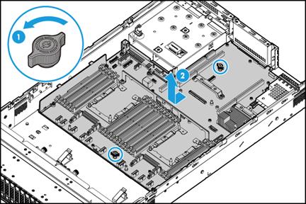
Installing the system board
1. Hold the system board by its handle and slowly place the system board in the chassis. Then, slide the system board toward the server rear until the connectors (for example, USB connectors and the Ethernet port) on it are securely seated, as shown by callout 1 in Figure 171.
|
|
NOTE: The connectors are securely seated if you cannot use the system board handle to lift the system board. |
2. Fasten the two captive screws on the system board, as shown by callout 2 in Figure 171.
Figure 171 Installing the system board
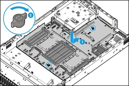
3. Install the removed processors and heatsinks. For more information, see "Installing processors."
4. Install the removed DIMMs. For more information, see "Installing DIMMs."
5. Install the removed NVMe VROC module. For more information, see "Installing the NVMe VROC module."
6. Install the removed mLOM Ethernet adapter. For more information, see "Installing an mLOM Ethernet adapter."
7. Install the removed Mezzanine storage controller. For more information, see "Installing a Mezzanine storage controller and a power fail safeguard module."
8. Install the removed PCIe riser cards and PCIe modules. For more information, see "Installing riser cards and PCIe modules."
9. Install the removed rear 2LFF or 4LFF drive cage. For more information, see "Installing a front or rear drive cage."
10. Connect cables to the system board.
11. Install the fan cage. For more information, see "Replacing the fan cage."
12. Install air baffles. For more information, see "Installing air baffles."
13. Install the access panel. For more information, see "Replacing the access panel."
14. Install the removed power supplies. For more information, see "Installing power supplies."
15. Rack-mount the server. For more information, see "Rack-mounting the server."
16. Connect the power cord. For more information, see "Connecting the power cord."
17. Power on the server. For more information, see "Powering on the server."
Verifying the replacement
Log in to HDM to verify that each part is operating correctly and no alert is generated. For more information, see HDM online help.
Replacing the drive expander module
|
|
WARNING! To avoid bodily injury from hot surfaces, allow the server and its internal modules to cool before touching them. |
Procedure
1. Power off the server. For more information, see "Powering off the server."
2. Remove the server from the rack. For more information, see "Removing the server from a rack."
3. Remove the access panel. For more information, see "Replacing the access panel."
4. Remove the chassis air baffle if it hinders the replacement. For more information, see "Removing air baffles."
5. Remove the fan cage if it hinders the replacement. For more information, see "Replacing the fan cage."
6. Disconnect cables from the expander module.
7. Loosen the captive screws that secure the expander module, and pull the expander module to disengage the pin holes from the guide pins. Then lift the module out of the chassis, as shown in Figure 172.
Figure 172 Removing a drive expander module (12LFF server)
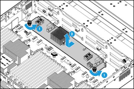
8. Install a new expander module.
¡ For the 12LFF server, place the new expander module in the chassis, align the pin holes on the expander module with the guide pins on the drive backplane, and push the expander module against the drive backplane. Fasten the captive screws to secure the expander module into place, as shown in Figure 173.
Figure 173 Installing a 12LFF drive expander module
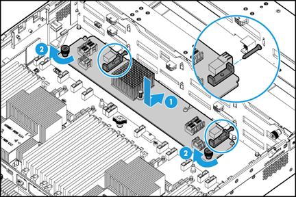
¡ For the 25SFF server, place the new expander module on the two support brackets in the chassis. Then slide the module towards the drive backplane until you cannot push it further. Fasten the captive screws to secure the expander module into place, as shown in Figure 174.
Figure 174 Installing a 25SFF drive expander module
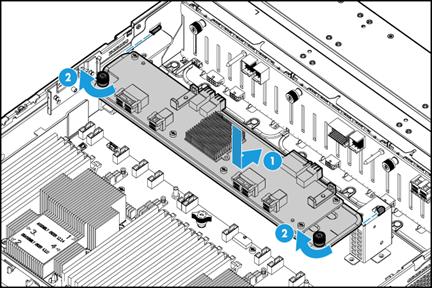
9. Connect cables to the drive expander module.
10. Install the removed fan cage. For more information, see "Replacing the fan cage."
11. Install the removed chassis air baffle. For more information, see "Installing air baffles."
12. Install the access panel. For more information, see "Replacing the access panel."
13. Rack-mount the server. For more information, see "Rack-mounting the server."
14. Connect the power cord. For more information, see "Connecting the power cord."
15. Power on the server. For more information, see "Powering on the server."
Verifying the replacement
Log in to HDM to verity that the drive expander module is in a correct state. For more information, see HDM online help.
Replacing drive backplanes
|
|
WARNING! To avoid bodily injury from hot surfaces, allow the server and its internal modules to cool before touching them. |
Removing drive backplanes
1. Power off the server. For more information, see "Powering off the server."
2. Remove the server from the rack. For more information, see "Removing the server from a rack."
3. Remove the access panel. For more information, see "Replacing the access panel."
4. Remove the chassis air baffle if it hinders the replacement. For more information, see "Removing air baffles."
5. Remove the fan cage if it hinders the replacement. For more information, see "Replacing the fan cage."
6. Remove the security bezel, if any. For more information, see "Replacing the security bezel."
7. Remove the drives attached to the backplane. For more information, see "Replacing a SAS/SATA drive."
8. Remove the drive expander module if it hinders drive backplane removal. For more information, see "Replacing the drive expander module."
9. Disconnect cables from the backplane.
10. Remove the drive backplanes:
¡ To remove the front drive backplane, loosen the captive screws on the backplane, slowly lift the backplane, and then pull it out of the chassis, as shown in Figure 175.
The removal procedure is the same for the available front drive backplanes. This procedure uses the front 25SFF drive backplane.
|
|
CAUTION: Do not use excessive force when lifting the drive backplane out of the chassis. Using excessive force might strike the components on the backplane against the chassis and damage the components. |
Figure 175 Removing a front 25SFF drive backplane
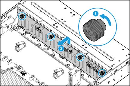
¡ To remove the rear drive backplane, loosen the captive screw on the backplane, slide the backplane rightward, and then pull the backplane out of the chassis, as shown in Figure 176.
The removal procedure is the same for the rear 2SFF, 4SFF, 2LFF, and 4LFF drive backplanes. This procedure uses the rear 2SFF drive backplane.
Figure 176 Removing a rear 2SFF drive backplane

Installing drive backplanes
1. Install drive backplanes:
¡ To install a front drive backplane, press the backplane against the drive bay, and then fasten the captive screws, as shown in Figure 177.
The installation procedure is the same for the available front drive backplanes. This procedure uses the front 25SFF drive backplane.
Figure 177 Installing the front 25SFF drive backplane
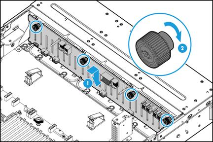
¡ To install the rear drive backplane, place the backplane in the slot, slide the backplane to cover the drive bay, and then fasten the captive screw, as shown in Figure 178.
The installation procedure is the same for the rear 2SFF, 4SFF, 2LFF, and 4LFF drive backplanes. This procedure uses the rear 2SFF drive backplane.
Figure 178 Installing the rear 2SFF drive backplane
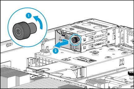
2. Connect cables to the drive backplanes. For more information, see "Connecting drive cables."
3. Install the removed drive expander module. For more information, see "Replacing the drive expander module."
4. Installed the removed drives. For more information, see "Installing SAS/SATA drives."
5. Install the removed security bezel. For more information, see "Installing the security bezel."
6. Install the removed fan cage. For more information, see "Installing fans."
7. Install the removed chassis air baffle. For more information, see "Installing air baffles."
8. Install the access panel. For more information, see "Replacing the access panel."
9. Rack-mount the server. For more information, see "Rack-mounting the server."
10. Connect the power cord. For more information, see "Connecting the power cord."
11. Power on the server. For more information, see "Powering on the server."
Verifying the replacement
Log in to HDM to verity that the drive backplanes are in a correct state. For more information, see HDM online help.
Replacing the SATA optical drive
|
|
WARNING! To avoid bodily injury from hot surfaces, allow the server and its internal modules to cool before touching them. |
To replace the SATA optical drive:
1. Power off the server. For more information, see "Powering off the server."
2. Remove the server from the rack. For more information, see "Removing the server from a rack."
3. Remove the access panel. For more information, see "Replacing the access panel."
4. Remove the chassis air baffle. For more information, see "Removing air baffles."
5. Remove the fan cage. For more information, see "Replacing the fan cage."
6. Remove the security bezel, if any. For more information, see "Replacing the security bezel."
7. Disconnect the cable from the optical drive.
8. Remove the screw that secures the optical drive, and then push the optical drive out of the slot from the inside of the chassis, as shown in Figure 179.
Figure 179 Removing the SATA optical drive
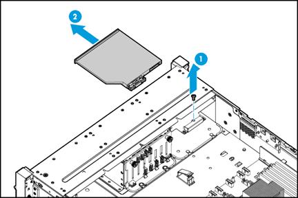
9. Install a new SATA optical drive. For more information, see "Installing a SATA optical drive."
10. Connect the optical drive cable.
11. Install the removed security bezel. For more information, see "Installing the security bezel."
12. Install the fan cage. For more information, see "Replacing the fan cage."
13. Install the chassis air baffle. For more information, see "Installing air baffles."
14. Install the access panel. For more information, see "Replacing the access panel."
15. Rack-mount the server. For more information, see "Rack-mounting the server."
16. Connect the power cord. For more information, see "Connecting the power cord."
17. Power on the server. For more information, see "Powering on the server."
Replacing the diagnostic panel
|
|
WARNING! To avoid bodily injury from hot surfaces, allow the server and its internal modules to cool before touching them. |
To replace the diagnostic panel:
1. Power off the server. For more information, see "Powering off the server."
2. Remove the server from the rack. For more information, see "Removing the server from a rack."
3. Remove the access panel. For more information, see "Replacing the access panel."
4. Remove the chassis air baffle if it hinders the replacement. For more information, see "Removing air baffles."
5. Remove the fan cage if it hinders the replacement. For more information, see "Replacing the fan cage."
6. Remove the security bezel, if any. For more information, see "Replacing the security bezel."
7. If the diagnostic panel cable is connected to the system board, disconnect the cable.
8. Remove the diagnostic panel:
|
|
NOTE: The removal procedure is similar for all the diagnostic panels. This section uses an SFF diagnostic panel as an example. |
a. Press the release button on the diagnostic panel, as shown by callout 1 in Figure 180. The diagnostic panel pops out.
b. Hold the diagnostic panel by its front edge to pull it out of the slot, as shown by callout 2 in Figure 180.
Figure 180 Removing the diagnostic panel
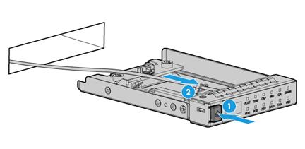
9. Install a new diagnostic panel. For more information, see "Installing a diagnostic panel."
10. Install the removed security bezel. For more information, see "Installing the security bezel."
11. Install the removed fan cage. For more information, see "Replacing the fan cage."
12. Install the removed chassis air baffle. For more information, see "Installing air baffles."
13. Install the access panel. For more information, see "Replacing the access panel."
14. Rack-mount the server. For more information, see "Rack-mounting the server."
15. Connect the power cord. For more information, see "Connecting the power cord."
16. Power on the server. For more information, see "Powering on the server."
Replacing the serial label pull tab module
A serial label pull tab module is available only for the 8SFF and 25SFF servers.
If sufficient space is available for replacement, you can replace the serial label pull tab module without powering off the server or removing the server from the rack. The following procedure is provided based on the assumption that no sufficient space is available for replacement.
To replace the serial label pull tab module:
1. Power off the server. For more information, see "Powering off the server."
2. Remove the server from the rack. For more information, see "Removing the server from a rack."
3. Remove the security bezel, if any. For more information, see "Replacing the security bezel."
4. Remove the serial label pull tab module. The removal method is the same for the serial label pull tab module and the diagnostic panel. For more information, see "Replacing the diagnostic panel."
5. Install a new serial label pull tab module. For more information, see "Installing a serial label pull tab module."
6. Install the removed security bezel. For more information, see "Installing the security bezel."
7. Rack-mount the server. For more information, see "Rack-mounting the server."
8. Connect the power cord. For more information, see "Connecting the power cord."
9. Power on the server. For more information, see "Powering on the server."
Replacing the chassis-open alarm module
|
|
WARNING! To avoid bodily injury from hot surfaces, allow the server and its internal modules to cool before touching them. |
The server supports the following types of chassis-open alarm modules:
· Independent chassis-open alarm module.
· Chassis-open alarm module attached to the left chassis ear (with VGA and USB 2.0 connectors).
Removing the chassis-open alarm module
1. Power off the server. For more information, see "Powering off the server."
2. Remove the server from the rack. For more information, see "Removing the server from a rack."
3. Remove the access panel. For more information, see "Replacing the access panel."
4. Remove the chassis-open alarm module:
a. Remove the screw that secures the chassis-open alarm module. Slide the module toward the rear of the server chassis to disengage the keyed slot in the module from the peg on the chassis, and pull the module out of the chassis, as shown by callouts 1 and 2 in Figure 181.
b. Disconnect the chassis-open alarm module cable from the chassis-open alarm module, front VGA, and USB 2.0 connector on the system board, as shown by callout 3 in Figure 181.
Figure 181 Removing the chassis-open alarm module
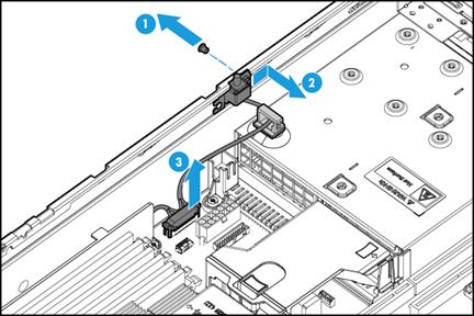
|
|
NOTE: The removal procedure is the same for the independent chassis-open alarm module and the chassis-open alarm module attached to the left chassis ear. This figure uses the chassis-open alarm module attached to the left chassis ear as an example. |
5. Remove the left chassis ear if the chassis-open alarm module is attached to the left chassis ear. For more information, see "Removing the left chassis ear."
Installing the chassis-open alarm module
1. Install the left chassis ear if the chassis-open alarm module is attached to the left chassis ear. For more information, see "Installing the left chassis ear."
2. Install the chassis-open alarm module:
a. Connect the chassis-open alarm module cable to the chassis-open alarm module, front VGA, and USB 2.0 connector on the system board, as shown by callout 1 in Figure 182.
b. Press the module against the chassis inside, with the notch of the keyed slot in the module aligned with the peg on the chassis.
c. Slide the module toward the server front to lock the module into place, and then fasten the screw, as shown by callouts 2 and 3 in Figure 182.
Figure 182 Installing the chassis-open alarm module
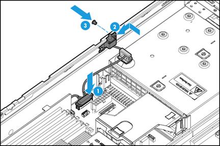
|
|
NOTE: The installation procedure is the same for the independent chassis-open alarm module and the chassis-open alarm module attached to the left chassis ear. This figure uses the chassis-open alarm module attached to the left chassis ear as an example. |
3. Install the access panel. For more information, see "Replacing the access panel."
4. Rack-mount the server. For more information, see "Rack-mounting the server."
5. Connect the power cord. For more information, see "Connecting the power cord."
6. Power on the server. For more information, see "Powering on the server."
Replacing chassis ears
|
|
WARNING! To avoid bodily injury from hot surfaces, allow the server and its internal modules to cool before touching them. |
Replacing the right chassis ear
Removing the right chassis ear
1. Power off the server. For more information, see "Powering off the server."
2. Remove the server from the rack. For more information, see "Removing the server from a rack."
3. Remove the access panel. For more information, see "Replacing the access panel."
4. Remove the chassis air baffle. For more information, see "Removing air baffles."
5. Remove the fan cage. For more information, see "Replacing the fan cage."
6. Remove the right chassis ear:
a. Disconnect the front I/O component cable assembly from the system board, as shown in Figure 183.
Figure 183 Disconnecting the front I/O component cable assembly from the system board

b. Remove the screw that secures the cable protection plate, slide the plate toward the rear of the chassis, and then remove it from the chassis, as shown by callouts 1 and 2 in Figure 184.
c. Pull the I/O component cable out of the slot, as shown by callout 3 in Figure 184.
Figure 184 Removing the cable protection plate
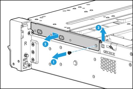
7. Remove the screws that secure the right chassis ear, and then pull the chassis ear until it is removed, as shown in Figure 185.
Figure 185 Removing the right chassis ear
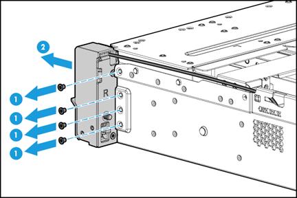
Installing the right chassis ear
1. Attach the right chassis ear to the right side of the server, and use screws to secure it into place, as shown in Figure 186.
Figure 186 Installing the right chassis ear
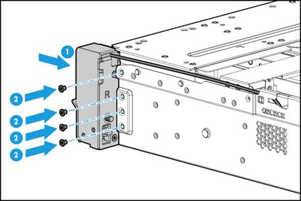
2. Connect the front I/O component cable assembly:
a. Insert the front I/O component cable assembly into the cable cutout, as shown by callout 1 in Figure 187.
b. Attach the cable protection plate to the chassis front of the server, with its keyed slots over the pegs on the chassis.
c. Slide the plate toward the server front to lock it onto the pegs, as shown by callout 2 in Figure 187.
d. Fasten the plate with its screw, with the front I/O LED cable (round cable) above the screw and the USB 3.0 connector cable (flat cable) below the screw, as shown by callout 3 in Figure 187.
Figure 187 Installing the cable protection plate

b. Connect the front I/O component cable assembly to the front I/O connector on the system board, as shown in Figure 188.
Figure 188 Connecting the front I/O component cable assembly
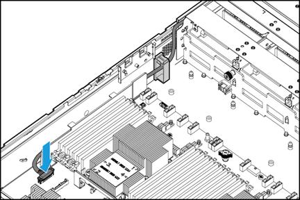
3. Install the fan cage. For more information, see "Replacing the fan cage."
4. Install the chassis air baffle. For more information, see "Installing air baffles."
5. Install the access panel. For more information, see "Replacing the access panel."
6. Rack-mount the server. For more information, see "Rack-mounting the server."
7. Connect the power cord. For more information, see "Connecting the power cord."
8. Power on the server. For more information, see "Powering on the server."
Replacing the left chassis ear
The server supports the following types of left chassis ears:
· Chassis ears with VGA and USB 2.0 connectors.
· Chassis ears without connectors.
|
|
NOTE: The replacement procedure is the same for the two types of left chassis ears except that you must remove the VGA and USB 2.0 cable and the chassis-open alarm module when you remove a left chassis ear with connectors. The subsequent procedures use the left chassis ear with VGA and USB connectors as an example. |
Removing the left chassis ear
1. Power off the server. For more information, see "Powering off the server."
2. Remove the server from the rack. For more information, see "Removing the server from a rack."
3. Remove the access panel. For more information, see "Replacing the access panel."
4. Remove the chassis air baffle. For more information, see "Removing air baffles."
5. Remove the fan cage. For more information, see "Replacing the fan cage."
6. Remove the chassis-open alarm module. For more information, see "Replacing the chassis-open alarm module."
7. Remove the left chassis ear. The removal procedure is the same for the left and right chassis ears. For more information, see "Removing the right chassis ear."
Installing the left chassis ear
1. Install the left chassis ear. The installation procedure is the same for the left and right chassis ears. For more information, see "Installing the right chassis ear."
2. Connect the VGA and USB 2.0 cable to the chassis-open alarm module, front VGA, and USB 2.0 connector on the system board. The connection procedure is the same for the VGA and USB 2.0 cable and the front I/O component cable assembly. For more information, see "Installing the right chassis ear."
3. Install the chassis-open alarm module. For more information, see "Installing the chassis-open alarm module."
4. Install the fan cage. For more information, see "Replacing the fan cage."
5. Install the chassis air baffle. For more information, see "Installing air baffles."
6. Install the access panel. For more information, see "Replacing the access panel."
7. Rack-mount the server. For more information, see "Rack-mounting the server."
8. Connect the power cord. For more information, see "Connecting the power cord."
9. Power on the server. For more information, see "Powering on the server."
Replacing the TPM/TCM
To avoid system damage, do not remove the installed TPM/TCM.
If the installed TPM/TCM is faulty, remove the system board, and contact H3C Support for system board and TPM/TCM replacement.
Connecting internal cables
Properly route the internal cables and make sure they are not squeezed.
Connecting drive cables
For more information about storage controller configurations, see "Drive configurations and numbering."
8SFF server
Front 8SFF SAS/SATA drive cabling
Use Table 15 to select the method for connecting the 8SFF SAS/SATA drive backplane to a storage controller depending on the type of the storage controller.
Table 15 8SFF SAS/SATA drive cabling methods
|
Storage controller |
Cabling method |
|
Embedded RSTe RAID controller |
See Figure 189. |
|
Mezzanine storage controller |
See Figure 190. |
|
Standard storage controller |
See Figure 191. |
Figure 189 8SFF SATA drive connected to the embedded RSTe RAID controller
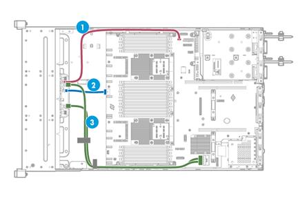
|
(1) AUX signal cable |
(2) Power cord |
(3) SATA data cable |
Figure 190 8SFF SAS/SATA drive connected to the Mezzanine storage controller
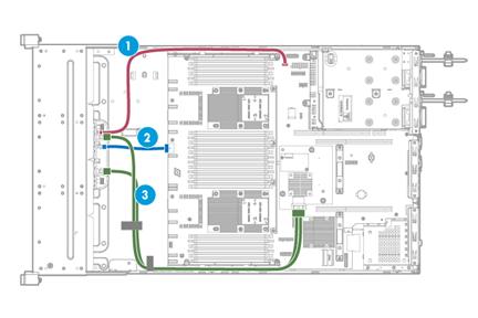
|
(1) AUX signal cable |
(2) Power cord |
(3) SAS/SATA data cable |
Figure 191 8SFF SAS/SATA drive connected to a standard storage controller
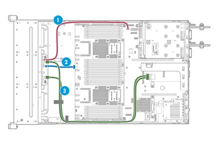
|
(1) AUX signal cable |
(2) Power cord |
(3) SAS/SATA data cable |
|
|
NOTE: The cabling method is the same for standard storage controllers in PCIe slots 2 and 6 of riser cards. This figure uses slot 6 as an example. |
Front 16SFF SAS/SATA drive cabling
Use Table 16 to select the method for connecting the front 16 SFF SAS/SATA drives to storage controllers depending on the storage controller configuration.
Table 16 16SFF SAS/SATA drive cabling methods
|
Storage controllers |
Cabling method |
Remarks |
|
· Mezzanine storage controller · Standard storage controller |
See Figure 192. |
· Connect drives in drive cage bay 2 to the Mezzanine storage controller. · Connect drives in drive cage bay 3 to the standard storage controller in PCIe slot 6. |
|
Standard storage controller UN-RAID-LSI-9460-16i(4G) |
See Figure 193. |
N/A |
|
Standard storage controllers |
See Figure 194. |
· Connect drives in drive cage bay 2 to the standard storage controller in PCIe slot 3. · Connect drives in drive cage bay 3 to the standard storage controller in PCIe slot 6. |
Figure 192 16SFF SAS/SATA drives connected to the Mezzanine and standard storage controllers
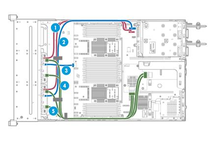
|
(1) AUX signal cables |
(2) and (3) Power cords |
|
(4) SAS/SATA data cable 1 (for drive cage bay 2) |
(5) SAS/SATA data cable 2 (for drive cage bay 3) |
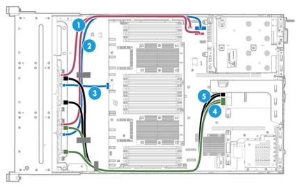
|
(1) AUX signal cables |
(2) and (3) Power cords |
|
(4) SAS/SATA data cable 1 |
(5) SAS/SATA data cable 2 |
Figure 194 16SFF SAS/SATA drives connected to the standard storage controllers
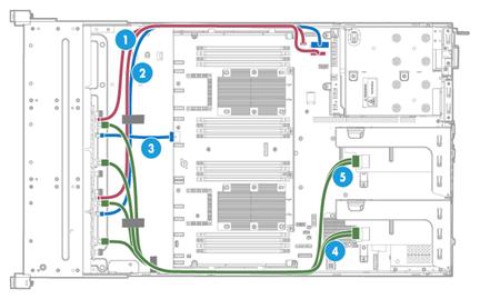
|
(1) AUX signal cables |
(2) and (3) Power cords |
|
(4) SAS/SATA data cable 1 (for drive cage bay 2) |
(5) SAS/SATA data cable 2 (for drive cage bay 3) |
Front hybrid 8SFF SAS/SATA and 8SFF NVMe drive cabling
To install 8SFF NVMe drives, you must install two 4-port NVMe SSD expander modules in PCIe slots 2 and 5 or an 8-port NVMe SSD expander module in PCIe slot 2.
When connecting NVMe data cables, make sure you connect the corresponding peer ports with the correct NVMe data cable. For 8-port and 4-port NVMe SSD expander modules, use Table 18 and Table 19, respectively, to determine the ports to be connected and the cable to use.
Use Table 17 to determine the front drive cabling method depending on the type of storage controller and NVMe SSD expander module.
Table 17 Hybrid 8SFF SAS/SATA and 8SFF NVMe drive cabling methods
|
Storage controller |
NVMe SSD expander module |
Cabling method |
|
Embedded RSTe RAID controller |
Two 4-port NVMe SSD expander modules |
See Figure 196. |
|
One 8-port NVMe SSD expander module |
See Figure 195. |
|
|
Mezzanine storage controller |
Two 4-port NVMe SSD expander modules |
See Figure 197. |
|
One 8-port NVMe SSD expander modules |
See Figure 198. |
|
|
Standard storage controller |
Two 4-port NVMe SSD expander modules |
· For 8SFF SAS/SATA drive cabling, see Figure 199. · For 8SFF NVMe drive cabling, see Figure 196. |
|
One 8-port NVMe SSD expander modules |
See Figure 199. |
Figure 195 Hybrid 8SFF SATA and 8SFF NVMe drive cabling (embedded RAID controller and 8-port NVMe SSD expander module)
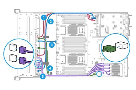
|
(1) AUX signal cables |
(2) and (3) Power cords |
|
(4) SATA data cable |
(5) NVMe data cables |
Figure 196 Hybrid 8SFF SAS/SATA and 8SFF NVMe drive cabling (embedded storage controller and 4-port NVMe SSD expander modules)
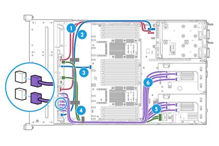
|
(1) AUX signal cables |
(2) and (3) Power cords |
|
(4) SAS/SATA data cable |
(5) and (6) NVMe data cables |
Figure 197 Hybrid 8SFF SATA and 8SFF NVMe drive cabling (Mezzanine RAID controller and 4-port NVMe SSD expander modules)
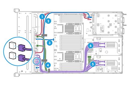
|
(1) AUX signal cables |
(2) and (3) Power cords |
|
(4) SATA data cable |
(5) and (6) NVMe data cables |
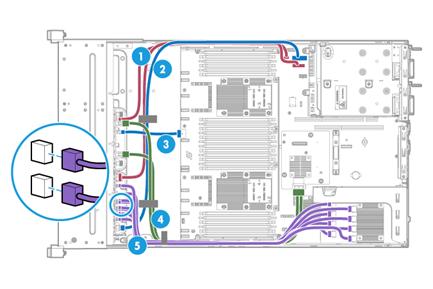
|
(1) AUX signal cables |
(2) and (3) Power cords |
|
(4) SAS/SATA data cable |
(5) NVMe data cables |
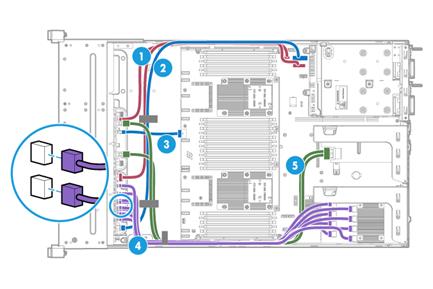
|
(1) AUX signal cables |
(2) and (3) Power cords |
|
(4) NVMe data cables |
(5) SAS/SATA data cable |
|
Mark on the NVMe data cable end |
Port on the drive backplane |
Port on the 8-port NVMe SSD expander module |
|
NVMe 1 |
NVMe A1 |
NVMe A1 |
|
NVMe 2 |
NVMe A2 |
NVMe A2 |
|
NVMe 3 |
NVMe A3 |
NVMe A3 |
|
NVMe 4 |
NVMe A4 |
NVMe A4 |
|
NVMe 1 |
NVMe B1 |
NVMe B1 |
|
NVMe 2 |
NVMe B2 |
NVMe B2 |
|
NVMe 3 |
NVMe B3 |
NVMe B3 |
|
NVMe 4 |
NVMe B4 |
NVMe B4 |
|
Mark on the NVMe data cable end |
Port on the drive backplane |
Port on the 4-port NVMe SSD expander modules |
|
NVMe 1 |
NVMe A1 |
NVMe 1 (NVMe SSD expander module in PCIe slot 2) |
|
NVMe 2 |
NVMe A2 |
NVMe 2 (NVMe SSD expander module in PCIe slot 2) |
|
NVMe 3 |
NVMe A3 |
NVMe 3 (NVMe SSD expander module in PCIe slot 2) |
|
NVMe 4 |
NVMe A4 |
NVMe 4 (NVMe SSD expander module in PCIe slot 2) |
|
NVMe 1 |
NVMe B1 |
NVMe 1 (NVMe SSD expander module in PCIe slot 5) |
|
NVMe 2 |
NVMe B2 |
NVMe 2 (NVMe SSD expander module in PCIe slot 5) |
|
NVMe 3 |
NVMe B3 |
NVMe 3 (NVMe SSD expander module in PCIe slot 5) |
|
NVMe 4 |
NVMe B4 |
NVMe 4 (NVMe SSD expander module in PCIe slot 5) |
Front hybrid 16SFF SAS/SATA and 8SFF NVMe drive cabling
To install 8SFF NVMe drives in drive cage bay 3, you must install an 8-port NVMe SSD expander module in PCIe slot 2.
When connecting NVMe data cables, make sure you connect the corresponding peer ports with the correct NVMe data cable. For 8-port and 4-port NVMe SSD expander modules, use Table 18 and Table 19, respectively, to determine the ports to be connected and the cable to use.
Use Table 20 to determine the front drive cabling method depending on the type of the storage controllers.
Table 20 Hybrid 16SFF SAS/SATA and 8SFF NVMe drive cabling methods
|
Storage controllers |
Cabling method |
Remarks |
|
RAID-LSI-9460-16i(4G) standard storage controller |
See Figure 200. |
· Connect SAS/SATA drives in drive cage bays 1 and 2 to the RAID-LSI-9460-16i(4G) standard storage controller in PCIe slot 6. · Connect NVMe drives in drive cage bay 3 to the 8-port NVMe SSD expander module in PCIe slot 2. |
|
Standard + Mezzanine storage controllers |
See Figure 201. |
· Connect SAS/SATA drives in drive cage bay 1 to the standard storage controller. · Connect SAS/SATA drives in drive cage bay 2 to the Mezzanine storage controller. · Connect NVMe drives in drive cage bay 3 to the 8-port NVMe SSD expander module in PCIe slot 2. |
|
Standard + standard storage controllers |
· See Figure 202 for connecting the power cords and AUX signal cables. · See Figure 203 for connecting the SAS/SATA data cables. · See Figure 204 for connecting the NVMe data cables. |
· Connect SAS/SATA drives in drive cage bay 1 to the standard storage controller in PCIe slot 6. Connect SAS/SATA drives in drive cage bay 2 to the standard storage controller in PCIe slot 8. Connect NVMe drives in drive cage bay 3 to the 4-port NVMe SSD expander modules in PCIe slot 2 and PCIe slot 5. |
Figure 200 Hybrid 16SFF SAS/SATA and 8SFF NVMe drive cabling (standard storage controller)
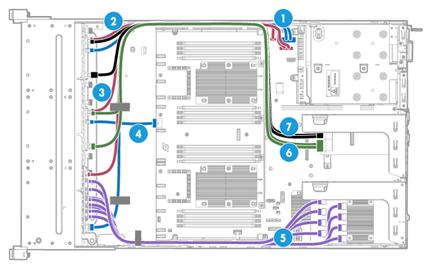
|
(1) and (4) Power cords |
(2) and (3) AUX signal cables |
|
(5) NVMe data cables |
(6) and (7) SAS/SATA data cables |
Figure 201 Hybrid 16SFF SAS/SATA and 8SFF NVMe drive cabling (standard and Mezzanine storage controllers)
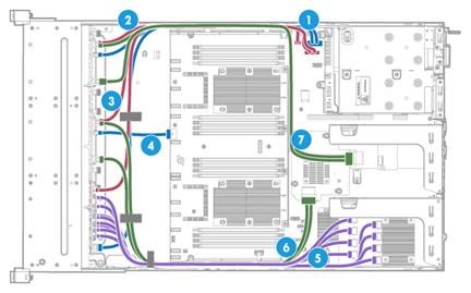
|
(1) and (4) Power cords |
(2) and (3) AUX signal cables |
|
(5) NVMe data cables |
(6) and (7) SAS/SATA data cables |
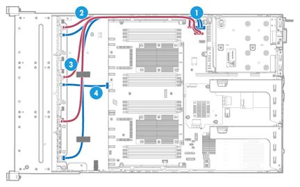
|
(1) and (4) Power cords |
(2) and (3) AUX signal cables |
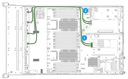
|
(1) SAS/SATA data cable 1 (bay 1) |
(2) SAS/SATA data cable 1 (bay 2) |
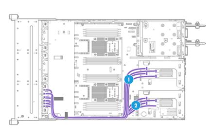
Front 24SFF SAS/SATA drive cabling
Connect SAS/SATA drives in drive cage bay 1 to the standard storage controller in PCIe slot 5, and the SAS/SATA drives in drive cages bay 2 and bay 3 to the RAID-LSI-9460-16i(4G) standard storage controller in PCIe slot 6. See Figure 205 for connecting AUX signal cables and power cords and Figure 206 for connecting SAS/SATA data cables.
· Connecting AUX signal cables and power cords
Figure 205 Connecting AUX signal cables and power cords

|
(1) and (4) Power cords |
(2) and (3) AUX signal cables |
· Connecting SAS/SATA data cables
Connect the SAS/SATA drives in drive cages bay 2 to C0 and C1 interfaces on the storage controller and the SAS/SATA drives in drive cages bay 3 to C2 and C3 interfaces.
Figure 206 Connecting SAS/SATA data cables
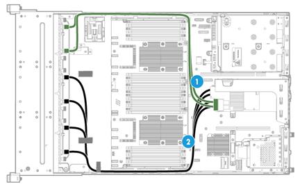
|
(1) SAS/SATA data cable 1 |
(2) SAS/SATA data cable 2 |
Front 8SFF NVMe drive cabling
To install 8SFF NVMe drives, you must install two 4-port NVMe SSD expander modules in PCIe slots 2 and 5 or an 8-port NVMe SSD expander module in PCIe slot 2.
When connecting NVMe data cables, make sure you connect the corresponding peer ports with the correct NVMe data cable. For 8-port and 4-port NVMe SSD expander modules, use Table 18 and Table 19, respectively, to determine the ports to be connected and the cable to use.
Use Table 21 to determine the front drive cabling method depending on the type of NVMe SSD expander module.
Table 21 8SFF NVMe drive cabling methods
|
NVMe SSD expander module |
Cabling method |
|
Two 4-port NVMe SSD expander modules |
See Figure 207. |
|
One 8-port NVMe SSD expander module |
See Figure 208. |
Figure 207 8SFF NVMe drive cabling (two 4-port NVMe SSD expander modules)
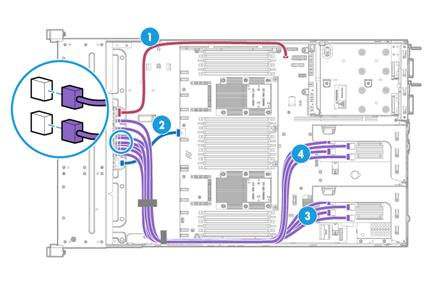
|
(1) AUX signal cable |
(2) Power cord |
(3) and (4) NVMe data cables |
Figure 208 8SFF NVMe drive cabling (one 8-port NVMe SSD expander module)
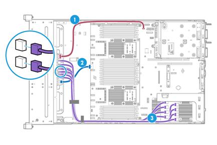
|
(1) AUX signal cable |
(2) Power cord |
(3) NVMe data cables |
Front 16SFF NVMe drive cabling
To install 16SFF NVMe drives, you must install two 8-port NVMe SSD expander modules in PCIe slots 2 and 5. Use Table 18 to determine the ports to be connected and the cable to use.
Figure 209 16SFF NVMe drive cabling (two 8-port NVMe SSD expander modules)
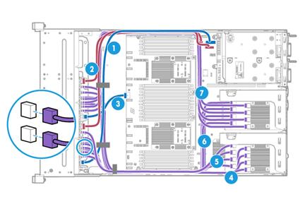
|
(1) and (3) Power cords |
(2) AUX signal cables |
(4) to (7) NVMe data cables |
Front hybrid 8SFF SAS/SATA and 16SFF NVMe drive cabling
To install 16SFF NVMe drives, you must install two 8-port NVMe SSD expander modules in PCIe slots 2 and 5. Use Table 18 to determine the ports to be connected and the cable to use.
Use Table 22 to determine the front drive cabling method depending on the type of the storage controller.
Table 22 Hybrid 8SFF SAS/SATA and 16SFF NVMe drive cabling methods
|
Storage controllers |
Cabling method |
|
Embedded RSTe RAID controller |
See Figure 210. |
|
Mezzanine storage controller |
See Figure 211. |
|
Storage controller |
See Figure 212. |
Figure 210 Hybrid 8SFF SAS/SATA and 16SFF NVMe drive cabling (embedded RSTe RAID controller)
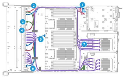
|
(1) and (5) Power cords |
(2) and (4) AUX signal cables |
|
(3) SAS/SATA data cable |
(6) and (7) NVMe data cables |
Figure 211 Hybrid 8SFF SAS/SATA and 16SFF NVMe drive cabling (Mezzanine storage controller)
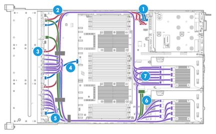
|
(1) and (4) Power cords |
(2) and (3) AUX signal cables |
|
(5) and (7) NVMe data cables |
(6) SAS/SATA data cables |
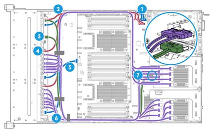
|
(1) and (5) Power cords |
(2) and (4) AUX signal cables |
|
(3) SAS/SATA data cable |
(6) and (7) NVMe data cables |
Front 24SFF NVMe drive cabling
To install 24SFF NVMe drives, you must install three 8-port NVMe SSD expander modules in PCIe slots 2, 5, and 7 or slots 1, 2, and 5.
If the BP-24SFF-NVMe-R4900-G3 drive backplane is not installed, use Table 18 to determine the ports to be connected and the cable to use. If the BP-24SFF-NVMe-R4900-G3 drive backplane is installed, use Table 24 to determine the ports to be connected and the cable to use.
Use Table 23 to determine the front drive cabling method depending on the drive backplane model.
Table 23 Front 24SFF NVMe drive cabling methods
|
Drive backplane |
Cabling method |
Remarks |
|
Any drive backplane except for the BP-24SFF-NVMe-R4900-G3 |
See Figure 213. |
Install three NVMe SSD expander modules in PCIe slots 2, 5, and 7. |
|
BP-24SFF-NVMe-R4900-G3 |
See Figure 214 and Figure 215. |
Install three NVMe SSD expander modules in PCIe slots 1, 2, and 5. |
Figure 213 24SFF NVMe drive cabling (any drive backplane except for the BP-24SFF-NVMe-R4900-G3)
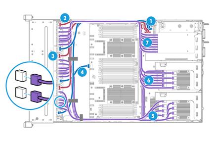
|
(1) and (4) Power cords |
(2) and (3) AUX signal cables |
(5) to (7) NVMe data cables |
Figure 214 24SFF NVMe drive cabling (drive backplane BP-24SFF-NVMe-R4900-G3)(1)

|
(1) NVMe data cables (P/N 0404A121) |
(2) NVMe data cables (P/N 0404A11Y) |
|
(3) NVMe data cables (P/N 0404A120) |
|
Figure 215 24SFF NVMe drive cabling (drive backplane BP-24SFF-NVMe-R4900-G3)(2)
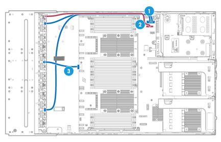
|
(1) and (3) Power cords |
(2) AUX signal cable |
|
Cable P/N |
Port on the drive backplane |
Mark on the NVMe data cable end |
Port on the 8-port NVMe SSD expander module |
|
|
Single-port end for the drive backplane |
Dual-port end for the NVMe SSD expander module |
|||
|
0404A121 |
NVMe A1 |
NVMe-A1 |
NVMe-A1 |
NVMe A1 |
|
NVMe-A2 |
NVMe A2 |
|||
|
NVMe A2 |
NVMe-A2 |
NVMe-A3 |
NVMe A3 |
|
|
NVMe-A4 |
NVMe A4 |
|||
|
NVMe A3 |
NVMe-A3 |
NVMe-B1 |
NVMe B1 |
|
|
NVMe-B2 |
NVMe B2 |
|||
|
NVMe A4 |
NVMe A4 |
NVMe-B3 |
NVMe B3 |
|
|
NVMe-B4 |
NVMe B4 |
|||
|
0404A11Y |
NVMe B1 |
NVMe-B1 |
NVMe-A1 |
NVMe A1 |
|
NVMe-A2 |
NVMe A2 |
|||
|
NVMe B2 |
NVMe-B2 |
NVMe-A3 |
NVMe A3 |
|
|
NVMe-A4 |
NVMe A4 |
|||
|
NVMe B3 |
NVMe-B3 |
NVMe-B1 |
NVMe B1 |
|
|
NVMe-B2 |
NVMe B2 |
|||
|
NVMe B4 |
NVMe-B4 |
NVMe-B3 |
NVMe B3 |
|
|
NVMe-B4 |
NVMe B4 |
|||
|
0404A120 |
NVMe-C1 |
NVMe-C1 |
NVMe-A1 |
NVMe A1 |
|
NVMe-A2 |
NVMe A2 |
|||
|
NVMe-C2 |
NVMe-C2 |
NVMe-A3 |
NVMe A3 |
|
|
NVMe-A4 |
NVMe A4 |
|||
|
NVMe-C3 |
NVMe-C3 |
NVMe-B1 |
NVMe B1 |
|
|
NVMe-B2 |
NVMe B2 |
|||
|
NVMe-C4 |
NVMe-C4 |
NVMe-B3 |
NVMe B3 |
|
|
NVMe-B4 |
NVMe B4 |
|||
25SFF server
Front 25SFF SAS/SATA drive cabling with the BP-25SFF-R4900 25SFF drive backplane
Use Table 25 to select the method for connecting the drive backplane to a storage controller depending on the type of the storage controller.
Table 25 25SFF SAS/SATA drive cabling methods
|
Storage controller |
Cabling method |
|
Mezzanine storage controller |
See Figure 216. |
|
Standard storage controller |
See Figure 217. |
Figure 216 25SFF SAS/SATA drive connected to the Mezzanine storage controller
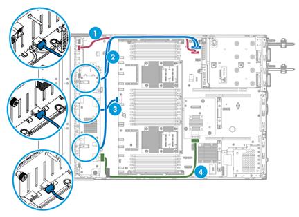
|
(1) AUX signal cable |
(2) Power cord 1 |
|
(3) Power cord 2 |
(4) SAS/SATA data cable |
Figure 217 25SFF SAS/SATA drive connected to a standard storage controller in PCIe slot 2
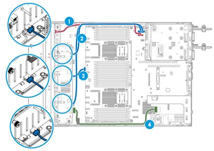
|
(1) AUX signal cable |
(2) Power cord 1 |
|
(3) Power cord 2 |
(4) SAS/SATA data cable |
Front 25SFF SAS/SATA drive cabling with the BP2-25SFF-2U-G3 25SFF drive backplane
Use Table 26 to select the method for connecting the drive backplane to a storage controller depending on the type of the storage controller.
Table 26 25SFF SAS/SATA drive cabling methods
|
Storage controller |
Cabling method |
|
Mezzanine storage controller |
See Figure 218. |
|
Standard storage controller |
See Figure 219. |
Figure 218 25SFF SAS/SATA drive connected to the Mezzanine storage controller
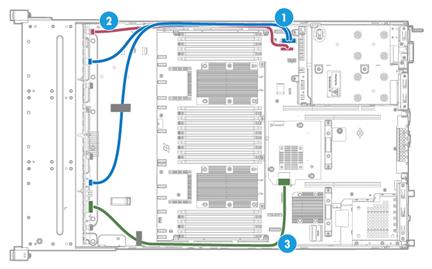
|
(1) Power cord |
(2) AUX signal cable |
(3) SAS/SATA data cable |
Figure 219 25SFF SAS/SATA drive connected to a standard storage controller in PCIe slot 6
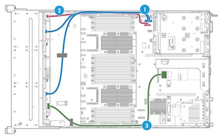
|
(1) Power cord |
(2) AUX signal cable |
(3) SAS/SATA data cable |
Rear 2SFF SAS/SATA drive cabling
Use Table 27 to select the method for connecting the rear 2SFF SAS/SATA drive cables for the 25SFF server depending on the type of the drive backplane.
Table 27 Rear 2SFF SAS/SATA drive cabling methods
|
Drive backplane |
Cabling method |
|
Drive backplane without functions of a drive expander module |
See Figure 220. |
|
Drive backplane with functions of a drive expander module |
See Figure 221. |
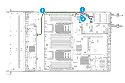
|
(1) SAS/SATA data cable |
(2) AUX signal cable |
(3) Power cord |
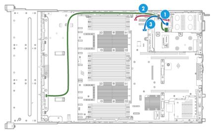
|
(1) AUX signal cable |
(2) Data cable |
(3) Power cord |
Rear 4SFF SAS/SATA drive cabling
Connect the rear 4SFF SAS/SATA drive cables for the 25SFF server as shown in Figure 222.
Figure 222 Rear 4SFF SAS/SATA drive cabling for the 25SFF server
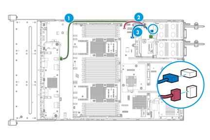
|
(1) SAS/SATA data cable |
(2) AUX signal cable |
(3) Power cord |
Rear 2LFF SAS/SATA drive cabling
Connect the rear 2LFF SAS/SATA drive cables for the 25SFF server as shown in Figure 223.
Figure 223 Rear 2LFF SAS/SATA drive cabling for the 25SFF server
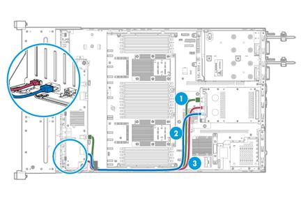
|
(1) SAS/SATA data cable |
(2) Power cord |
(3) AUX signal cable |
8LFF server
Use Table 28 to select the method for connecting the 8LFF drive backplane to a storage controller depending on the type of the storage controller.
Table 28 8LFF drive cabling methods
|
Storage controller |
Cabling method |
|
Embedded RSTe RAID controller |
See Figure 224. |
|
Mezzanine storage controller |
See Figure 225. |
|
Standard storage controller |
See Figure 226. |
Figure 224 8LFF SATA drive connected to the embedded RSTe RAID controller
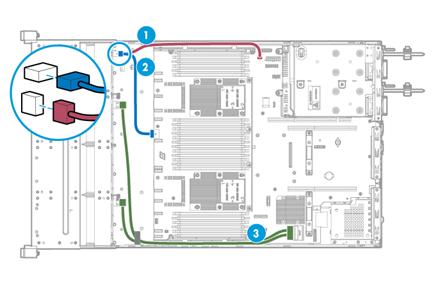
|
(1) AUX signal cable |
(2) Power cord |
(3) SATA data cable |
Figure 225 8LFF SAS/SATA drive connected to the Mezzanine storage controller
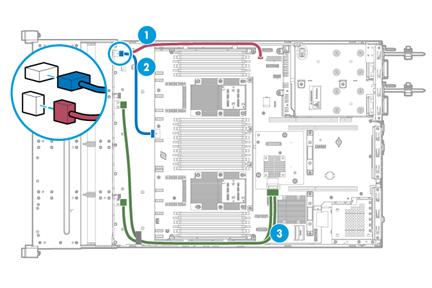
|
(1) AUX signal cable |
(2) Power cord |
(3) SAS/SATA data cable |
Figure 226 8LFF SAS/SATA drive connected to a standard storage controller
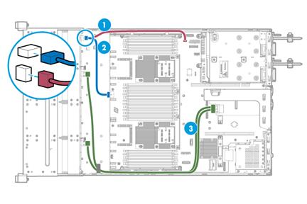
|
(1) AUX signal cable |
(2) Power cord |
(3) SAS/SATA data cable |
|
|
NOTE: The cabling method is the same for standard storage controllers in PCIe slots 2 and 6. This figure uses slot 6 as an example. |
12LFF server
Front 12LFF SAS/SATA drive cabling with the BP-12LFF-R4900 drive backplane
Use Table 29 to select the method for connecting the 12LFF drive backplane to a storage controller depending on the type of the storage controller.
Table 29 12LFF drive cabling methods
|
Storage controller |
Cabling method |
|
Mezzanine storage controller |
See Figure 227. |
|
Standard storage controller |
See Figure 228. |
Figure 227 12LFF SAS/SATA drive connected to the Mezzanine storage controller
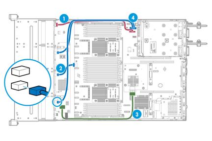
|
(1) AUX signal cable |
(2) Power cord 1 |
|
(3) SAS/SATA data cable |
(4) Power cord 2 |
Figure 228 12LFF SAS/SATA drive connected to a standard storage controller
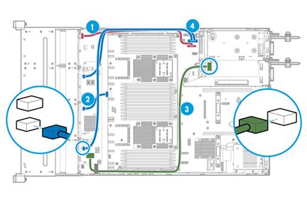
|
(1) AUX signal cable |
(2) Power cord 1 |
|
(3) SAS/SATA data cable |
(4) Power cord 2 |
|
|
NOTE: The cabling method is the same for standard storage controllers in PCIe slots 2 and 8. This figure uses slot 8 as an example. |
Front hybrid 8LFF SAS/SATA and 4LFF NVMe drive cabling with the BP-12LFF-NVMe-2U-G3 or BP-12LFF-4UniBay-2U drive backplane
To install 4LFF NVMe drives, you must install a 4-port NVMe SSD expander module in PCIe slot 2 or 5 as required.
When connecting NVMe data cables, make sure you connect the corresponding peer ports with the correct NVMe data cable. Use Table 31 to determine the ports to be connected and the cable to use.
Use Table 30 to determine the front drive cabling method depending on the type of storage controller.
Table 30 Hybrid 8LFF SAS/SATA and 4LFF NVMe drive cabling methods
|
Storage controller |
Cabling method |
Remarks |
|
Embedded RSTe RAID controller |
See Figure 229. |
Install the NVMe SSD expander module in PCIe slot 2. |
|
Mezzanine storage controller |
See Figure 230. |
Install the NVMe SSD expander module in PCIe slot 2. |
|
Standard storage controller |
See Figure 231. |
Install the NVMe SSD expander module in PCIe slot 5 and the standard storage controller in PCIe slot 6. |
Figure 229 Hybrid 8LFF SAS/SATA and 4LFF NVMe drive cabling (embedded RAID controller)
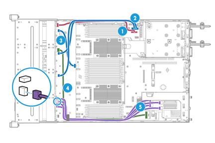
|
(1) AUX signal cable |
(2) and (3) Power cords |
|
(4) SAS/SATA data cable |
(5) NVMe data cables |
Figure 230 Hybrid 8LFF SAS/SATA and 4LFF NVMe drive cabling (Mezzanine storage controller)
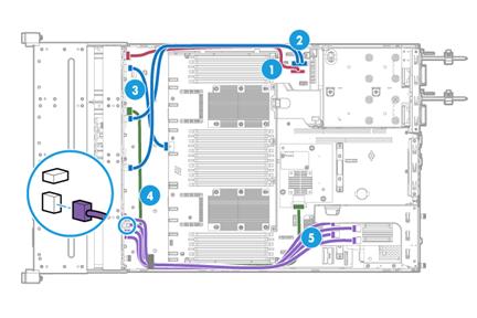
|
(1) AUX signal cable |
(2) and (3) Power cords |
|
(4) SAS/SATA data cable |
(5) NVMe data cables |
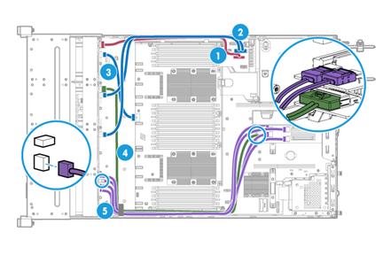
|
(1) AUX signal cable |
(2) and (3) Power cords |
|
(4) SAS/SATA data cable |
(5) NVMe data cables |
|
Mark on the NVMe data cable end |
Port on the drive backplane |
Port on the NVMe SSD expander module |
|
NVMe 1 |
NVMe A1 |
NVMe 1 |
|
NVMe 2 |
NVMe A2 |
NVMe 2 |
|
NVMe 3 |
NVMe A3 |
NVMe 3 |
|
NVMe 4 |
NVMe A4 |
NVMe 4 |
Front hybrid 8LFF SAS/SATA and 4LFF NVMe and rear 2SFF SAS/SATA drive cabling with the BP-12LFF-NVMe-2U-G3 or BP-12LFF-4UniBay-2U drive backplane
Connect the rear 2SFF SAS/SATA drives to the standard storage controller in PCIe slot 2, front 8LFF SAS/SATA drives to the standard storage controller in PCIe slot 1, and front 4LFF NVMe drives to the 4-port NVMe SSD expander module in PCIe slot 5.
· See Figure 231 for connecting AUX signal cables and power cords for the front drives.
· See Figure 232 for connecting AUX signal cables and power cords for the rear drives.
Figure 232 Connecting AUX signal cables and power cords for the rear drives
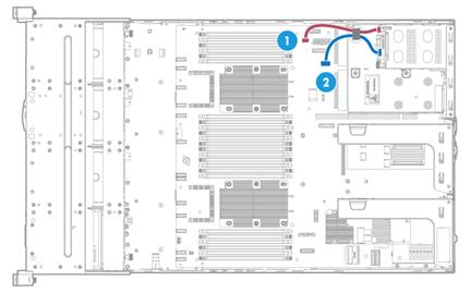
|
(1) AUX signal cable |
(2) Power cord |
· See Figure 233 for connecting SAS/SATA data cables.
Figure 233 Connecting SAS/SATA data cables
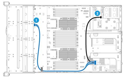
|
(1) SAS/SATA data cable 1 |
(2) SAS/SATA data cable 2 |
· See Figure 234 for connecting NVMe data cables.
When connecting NVMe data cables, make sure you connect the corresponding peer ports with the correct NVMe data cable. Use Table 31 to determine the ports to be connected and the cable to use.
Figure 234 Connecting NVMe data cables
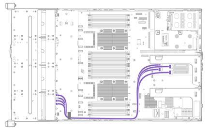
Front hybrid 8LFF SAS/SATA and 4LFF NVMe and rear 2SFF NVMe drive cabling with the BP-12LFF-NVMe-2U-G3 or BP-12LFF-4UniBay-2U drive backplane
Connect the rear 2SFF NVMe drives to the standard storage controller in PCIe slot 2, front 8LFF SAS/SATA drives to the standard storage controller in PCIe slot 1, and front 4LFF NVMe drives to the 4-port NVMe SSD expander module in PCIe slot 5.
· See Figure 231 for connecting AUX signal cables and power cords for the front drives.
· See Figure 232 for connecting AUX signal cables and power cords for the rear drives,.
· See Figure 235 for connecting data cables for the front 8LFF SAS/SATA drives.
Figure 235 Connecting data cables for the front 8LFF SAS/SATA drives
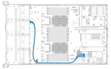
· See Figure 234 for connecting data cables for the front 4LFF NVMe drives.
When connecting NVMe data cables, make sure you connect the corresponding peer ports with the correct NVMe data cable. Use Table 31 to determine the ports to be connected and the cable to use.
· See Figure 236 for connecting data cables for the rear 2SFF NVMe drives.
Figure 236 Connecting data cables for the rear 2SFF NVMe drives
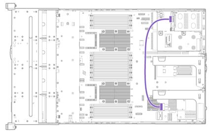
Front hybrid 8LFF SAS/SATA and 4LFF SAS/SATA/NVMe drive cabling with the BP-12LFF-NVMe-2U-G3 drive backplane with the BP-12LFF-NVMe-2U-G3 or BP-12LFF-4UniBay-2U drive backplane
To install 4LFF NVMe drives, you must install a 4-port NVMe SSD expander module in PCIe slot 5.
When connecting NVMe data cables, make sure you connect the corresponding peer ports with the correct NVMe data cable. Use Table 31 to determine the ports to be connected and the cable to use.
Use Table 30 to select the front drive cabling method depending on the type of storage controller.
Table 32 Hybrid 8LFF SAS/SATA and 4LFF SAS/SATA/NVMe drive cabling methods
|
Storage controller |
Cabling method |
Description |
|
Standard storage controller RAID-LSI-9460-16i(4G) |
See Figure 237. |
Connect SAS/SATA drives to the standard storage controller in PCIe slot 6. |
|
Mezzanine + standard storage controllers |
See Figure 238. |
· Connect SAS/SATA drives 0 through 7 to the Mezzanine storage controller. · Connect SAS/SATA drives 8 through 11 to the standard storage controller in PCIe slot 6. |
|
Standard storage controllers |
See Figure 239. |
Connect SAS/SATA drives to the standard storage controllers in PCIe slots 1 and 2. |
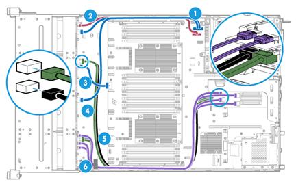
|
(1) to (3) Power cords |
(2) AUX signal cable |
|
(4) and (5) SAS/SATA data cables |
(6) NVMe data cables |
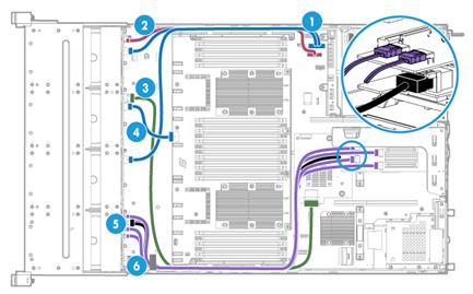
|
(1) and (4) Power cords |
(2) AUX signal cable |
|
(3) and (5) SAS/SATA data cables |
(6) NVMe data cables |
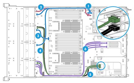
|
(1) and (3) Power cords |
(2) AUX signal cable |
|
(4) and (5) SAS/SATA data cables |
(6) NVMe data cables |
Hybrid front 8LFF SAS/SATA and 4LFF SAS/SATA/NVMe drive and rear 2SFF SAS/SATA drive cabling with the BP-12LFF-NVMe-2U-G3 or BP-12LFF-4UniBay-2U drive backplane
To use this drive configuration, install a 4-port NVMe SSD expander module in PCIe slot 5, a standard storage controller in PCIe slot 6, and a Mezzanine storage controller. Connect front drives 8 through 11 and rear 2SFF drives to the standard storage controller and connect front drives 0 through 7 to the Mezzanine storage controller.
When connecting NVMe data cables, make sure you connect the corresponding peer ports with the correct NVMe data cable. Use Table 31 to determine the ports to be connected and the cable to use.
Select the method for connecting the drive backplane to storage controllers depending on the types of the storage controllers.
· Connect front drives 0 through 7 to the Mezzanine storage controller, front SAS/SATA drives 8 through 11 and rear 2SFF SAS/SATA drives to the standard storage controller in PCIe slot 6. If NVMe drives are installed in slots 8 through 11, connect them to the 4-port NVMe SSD expander module in PCIe slot 5. See Figure 240 for the cable connections.
Figure 240 Front hybrid 8LFF SAS/SATA and 4LFF SAS/SATA/NVMe and rear 2SFF SAS/SATA drive cabling
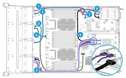
|
(1) AUX signal cable |
(2) and (4) Power cords |
|
(3) and (6) SAS/SATA data cables |
(5) NVMe data cables |
· Connect rear 2SFF SAS/SATA drives to the standard storage controller in PCIe slot 1, front SAS/SATA drives to the RAID-LSI-9460-16i(4G) storage controller in PCIe slot 6, and front NVMe drives to the 4-port NVMe SSD expander module in PCIe slot 5.
¡ See Table 30Figure 231 for connecting AUX signal cables and power cords for the front drives.
¡ See Figure 232 for connecting AUX signal cables and power cords for the rear drives.
¡ See Figure 241 for connecting data cables for the front SAS/SATA drives.
Connect SAS/SATA data cables from the front drives 0 through 7 to C0 and C1 interfaces on the storage controller and the front drives 8 to 11 to C2 and C3 interfaces.
Figure 241 Connecting data cables for front SAS/SATA drives
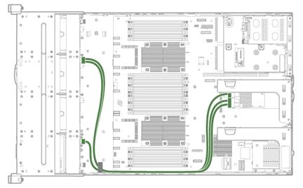
¡ See Figure 241 for connecting data cables for the rear SAS/SATA drives.
Figure 242 Connecting data cables for rear SAS/SATA drives
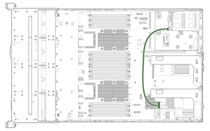
¡ See Figure 234 for connecting data cable for NVMe drives.
Front 12LFF SAS/SATA/NVMe and rear 2SFF SAS/SATA drive cabling with the BP-12LFF-NVMe-2U-G3 or BP-12LFF-4UniBay-2U drive backplane
Select the method for connecting the drive backplane to storage controllers depending on the types of the storage controllers.
· Connect front drives 0 through 7 to the Mezzanine storage controller, front SAS/SATA drives 8 through 11 and rear 2SFF SAS/SATA drives to the standard storage controller in PCIe slot 6. See Figure 240 shows the cable connections.
· Connect rear 2SFF SAS/SATA drives to the standard storage controller in PCIe slot 1, front SAS/SATA drives to the RAID-LSI-9460-16i(4G) storage controller in PCIe slot 6.
¡ See Table 30Figure 231 for connecting AUX signal cables and power cords for the front drives.
¡ See Figure 232 for connecting AUX signal cables and power cords for the rear drives.
¡ See Figure 241 for connecting data cables for the rear SAS/SATA drives.
Front 12LFF SAS/SATA drive cabling with the BP2-12LFF-2U-G3 drive backplane
Use Table 29 to select the method for connecting the 12LFF drive backplane to a storage controller depending on the type of the storage controller.
Table 33 12LFF drive cabling methods
|
Storage controller |
Cabling method |
|
Mezzanine storage controller |
See Figure 243. |
|
Standard storage controller |
See Figure 244. |
Figure 243 12LFF SAS/SATA drive connected to the Mezzanine storage controller
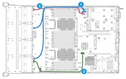
|
(1) Power cord |
(2) AUX signal cable |
(3) SAS/SATA data cable |
Figure 244 12LFF SAS/SATA drive connected to the standard storage controller in PCIe slot 6
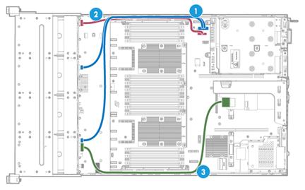
|
(1) Power cord |
(2) AUX signal cable |
(3) SAS/SATA data cable |
Hybrid front 12LFF SAS/SATA drive and rear 2SFF SAS/SATA drive cabling with the BP-12LFF-G3 drive backplane
Use Table 34 to select the method for connecting the drive backplane to storage controllers depending on the types of the storage controllers.
Table 34 12LFF drive cabling methods
|
Storage controller |
Cabling method |
Remarks |
|
Standard storage controllers |
See Figure 245. |
· Connect front drives 0 through 7 to the standard storage controller in PCIe slot 1. · Connect front drives 8 through 11 and rear 2 SFF drives to the standard storage controller in PCIe slot 2. |
|
Mezzanine + standard storage controllers |
See Figure 246. |
· Connect front drives 0 through 7 to the Mezzanine storage controller. · Connect front drives 8 through 11 and rear 2 SFF drives to the standard storage controller in PCIe slot 6. |
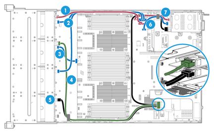
|
(1) and (7) AUX signal cables |
(2), (3), and (6) Power cords |
(4) and (5) SAS/SATA data cables |
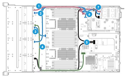
|
(1) and (7) AUX signal cables |
(2), (3), and (6) Power cords |
(4) and (5) SAS/SATA data cables |
Rear 2SFF SAS/SATA drive cabling
Use Table 35 to select the rear 2SFF SAS/SATA drive cabling method depending on the drive backplane model.
Table 35 Rear 2SFF SAS/SATA drive cabling methods for the 12LFF server
|
Drive backplane |
Cabling method |
|
Any drive backplane except for the BP2-12LFF-2U-G3 |
See Figure 247. |
|
BP2-12LFF-2U-G3 |
See Figure 248. |
Figure 247 Rear 2SFF drive cabling for the 12LFF server (any drive backplane except for the BP2-12LFF-2U-G3)
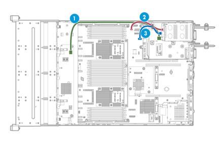
|
(1) SAS/SATA data cable |
(2) AUX signal cable |
(3) Power cord |
Figure 248 Rear 2SFF drive cabling for the 12LFF server (BP2-12LFF-2U-G3 drive backplane)
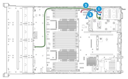
|
(1) AUX signal cable |
(2) data cable |
(3) Power cord |
Rear 4SFF SAS/SATA drive cabling
Connect the rear 4SFF drive cables for the 12LFF server as shown in Figure 249.
Figure 249 Rear 4SFF drive cabling for the 12LFF server
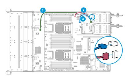
|
(1) SAS/SATA data cable |
(2) AUX signal cable |
(3) Power cord |
Rear 4SFF SAS/SATA/NVMe drive cabling (4SFF UniBay drive cage)
Connect the rear 4SFF SAS/SATA/NVMe drive cables for the 12LFF server as shown in Figure 250.
When connecting NVMe data cables, make sure you connect the corresponding peer ports with the correct NVMe data cable. Use Table 36 to determine the ports to be connected and the cable to use.
Figure 250 Rear 4SFF SAS/SATA/NVMe drive cabling for the 12LFF server

|
(1) SAS/SATA data cable |
(2) AUX signal cable |
|
(3) Power cord |
(4) and (5) NVMe data cables |
|
Port on the drive backplane |
Mark on the NVMe data cable end for the drive backplane |
Mark on the NVMe data cable end for the expander module |
Port on the NVMe SSD expander module |
|
NVMe 1 |
NVMe 1 |
NVMe 1 |
NVMe 1 |
|
NVMe 2 |
NVMe 2 |
||
|
NVMe 2 |
NVMe 2 |
NVMe 3 |
NVMe 3 |
|
NVMe 4 |
NVMe 4 |
Rear 2SFF SAS/SATA/NVMe drive cabling (2SFF UniBay drive cage)
Connect the rear 2SFF SAS/SATA/NVMe drive cables for the 12LFF server as shown in Figure 251.
When connecting NVMe data cables, make sure you connect the corresponding peer ports with the correct NVMe data cable. Use Table 37 to determine the ports to be connected and the cable to use.
Figure 251 Rear 2SFF SAS/SATA/NVMe drive cabling for the 12LFF server
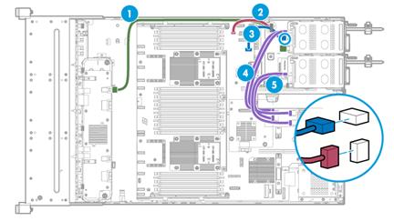
|
(1) SAS/SATA data cable |
(2) AUX signal cable |
|
(3) Power cord |
(4) and (5) NVMe data cable |
|
Port on the drive backplane |
Mark on the NVMe data cable end for the drive backplane |
Mark on the NVMe data cable end for the expander module |
Port on the NVMe SSD expander module |
|
NVMe |
2SFF NVMe |
NVMe 1 |
NVMe 1 |
|
NVMe 2 |
NVMe 2 |
Rear 2LFF SAS/SATA drive cabling
Use Table 38 to select the rear 2LFF SAS/SATA drive cabling method depending on the drive backplane model.
Table 38 Rear 2LFF SAS/SATA drive cabling methods for the 12LFF server
|
Drive backplane and expander module |
Cabling method |
|
Any drive backplane except for the BP2-12LFF-2U-G3 |
See Figure 252. |
|
BP2-12LFF-2U-G |
See Figure 253. |
Figure 252 Rear 2LFF drive cabling for the 12LFF server (any drive backplane except for the BP2-12LFF-2U-G3)
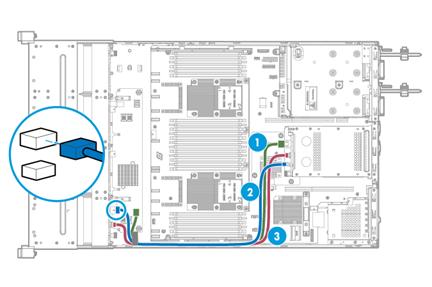
|
(1) SAS/SATA data cable |
(2) Power cord |
(3) AUX signal cable |
Figure 253 Rear 2LFF drive cabling for the 12LFF server (BP2-12LFF-2U-G drive backplane)
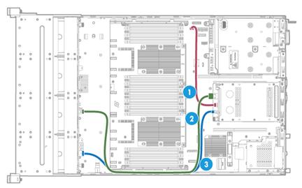
|
(1) AUX signal cable |
(2) SAS/SATA data cable |
(3) Power cord |
Rear 4LFF SAS/SATA drives
Connect the rear 4LFF drive cables for the 12LFF server as shown in Figure 254.
Figure 254 Rear 4LFF drive cabling for the 12LFF server
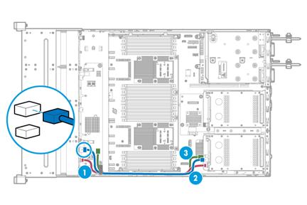
|
(1) AUX signal cable |
(2) Power cord |
(3) SAS/SATA data cable |
Connecting the flash card and the supercapacitor of the power fail safeguard module
Connecting the flash card on the Mezzanine storage controller
Connect the flash card on the Mezzanine storage controller to the supercapacitor as shown in Figure 255.
Figure 255 Connecting the flash card on the Mezzanine storage controller
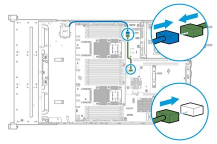
Connecting the flash card on a standard storage controller
The cabling method is similar for standard storage controllers in any PCIe slots. Figure 256 uses slot 1 to show the cabling method.
Figure 256 Connecting the flash card on a standard storage controller
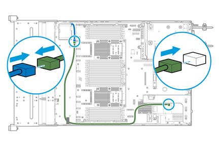
Connecting the power cord of a GPU module
The following GPU modules require a power cord:
· GPU-M4000-1-X.
· GPU-K80-1.
· GPU-M60-1-X.
· GPU-P40-X.
· GPU-M10-X.
· GPU-P100.
· GPU-V100-32G.
· GPU-V100.
Connect the power cord of a GPU module as shown in Figure 257.
Figure 257 Connecting the power cord of a GPU module
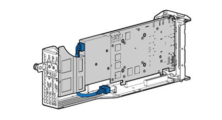
Connecting the NCSI cable for a PCIe Ethernet adapter
The cabling method is the same for standard storage controllers in any PCIe slots. Figure 258 uses slot 1 to show the cabling method.
Figure 258 Connecting the NCSI cable for a PCIe Ethernet adapter
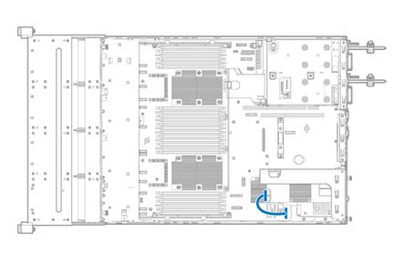
Connecting the SATA M.2 SSD cable
Connecting the front SATA M.2 SSD cable
If you install SATA M.2 SSDs at the server front, connect the front SATA M.2 SSD cable.
The SATA M.2 SSD cabling method depends on the number of SATA M.2 SSDs to be installed.
· If you are installing only one SATA M.2 SSD, connect the cable as shown in Figure 259.
· If you are installing two SATA M.2 SSDs, connect the cable as shown in Figure 260.
The front SATA M.2 SSD cable can transmit power to the drive backplane. For a 16SFF SAS/SATA drive configuration or an 8SFF SAS/SATA+8SFF NVMe drive configuration, first disconnect the power cord from the drive backplane of drive cage bay 3. Then, connect the gray cable to the power connector on the drive backplane of drive cage bay 3.
Figure 259 Connecting the front SATA M.2 SSD cable (one SATA M.2 SSD)
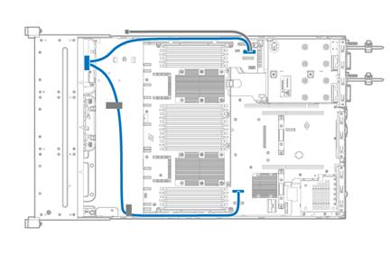
Figure 260 Connecting the front SATA M.2 SSD cable (two SATA M.2 SSDs)
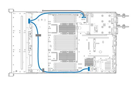
Connecting the rear SATA M.2 SSD cable
The rear SATA M.2 SSD cabling method depends on the number of SATA M.2 SSDs to be installed.
· If you are installing only one SATA M.2 SSD, connect the cable as shown in Figure 261.
· If you are installing two SATA M.2 SSDs, connect the cable as shown in Figure 262.
Figure 261 Connecting the rear SATA M.2 SSD cable (one SATA M.2 SSD)
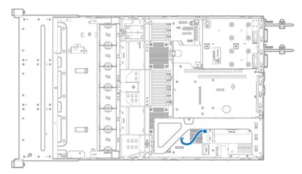
Figure 262 Connecting the rear SATA M.2 SSD cable (two SATA M.2 SSDs)
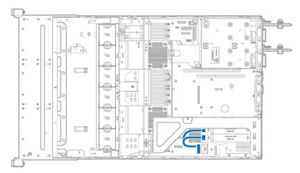
Connecting the SATA optical drive cable
Connect the SATA optical drive cable as shown in Figure 263.
Figure 263 Connecting the SATA optical drive cable

Connecting the front I/O component cable assembly
The front I/O component cable assembly is a two-to-one cable attached to the right chassis ear. Connect the cable to the front I/O component connector on the system board as shown in Figure 264.
Figure 264 Connecting the front I/O component cable assembly
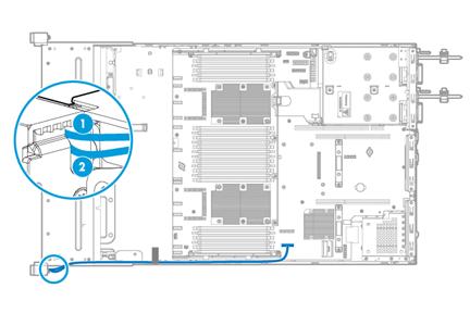
|
(1) Front I/O LED cable |
(2) USB 3.0 connector cable |
Connecting the cable for the front VGA and USB 2.0 connectors on the left chassis ear
Connect the cable for the front VGA and USB 2.0 connectors on the left chassis ear as shown in Figure 265.
Figure 265 Connecting the cable for the front VGA and USB 2.0 connectors on the left chassis ear
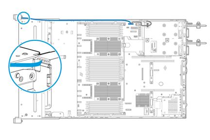
Connecting the diagnostic panel cable
Two cabling methods for diagnostic panels are available, as shown in Figure 266 and Figure 267. Select a cabling method depending on the drive backplane in the server. For more information, see "Installing a diagnostic panel."
Figure 266 Connecting the diagnostic panel cable (1)
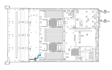
Figure 267 Connecting the diagnostic panel cable (2)
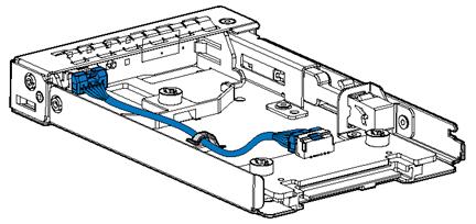
Maintenance
The following information describes the guidelines and tasks for daily server maintenance.
Guidelines
· Keep the equipment room clean and tidy. Remove unnecessary devices and objects from the equipment room.
· Make sure the temperature and humidity in the equipment room meet the server operating requirements.
· Regularly check the server from HDM for operating health issues.
· Keep the operating system and software up to date as required.
· Make a reliable backup plan:
¡ Back up data regularly.
¡ If data operations on the server are frequent, back up data as needed in shorter intervals than the regular backup interval.
¡ Check the backup data regularly for data corruption.
· Stock spare components on site in case replacements are needed. After a spare component is used, prepare a new one.
· Keep the network topology up to date to facilitate network troubleshooting.
Maintenance tools
The following are major tools for server maintenance:
· Hygrothermograph—Monitor the operating environment of the server.
· HDM and FIST—Monitor the operating status of the server.
Maintenance tasks
Observing LED status
Observe the LED status on the front and rear panels of the server to verify that the server modules are operating correctly. For more information about the status of the front and rear panel LEDs, see front panel and rear panel in "Appendix A Server specifications."
Monitoring the temperature and humidity in the equipment room
Use a hygrothermograph to monitor the temperature and humidity in the equipment room.
The temperature and humidity in the equipment room must meet the server requirements described in "Appendix A Server specifications."
Examining cable connections
Verify that the cables and power cords are correctly connected.
Guidelines
· Do not use excessive force when connecting or disconnecting cables.
· Do not twist or stretch the cables.
· Organize the cables appropriately. For more information, see "Cabling guidelines."
Checklist
· The cable type is correct.
· The cables are correctly and firmly connected and the cable length is appropriate.
· The cables are in good condition and are not twisted or corroded at the connection point.
Technical support
· Log and sensor information:
¡ Log information:
- Event logs, HDM logs, and SDS logs in HDM.
- Logs in iFIST.
¡ Sensor information in HDM.
· Product serial number.
· Product model and name.
· Snapshots of error messages and descriptions.
· Hardware change history, including installation, replacement, insertion, and removal of hardware.
· Third-party software installed on the server.
· Operating system type and version.
·
Appendix A Server specifications
A UIS-Cell 3000 G3 HCI system contains a server hardware platform, an HCI core, and a management platform called UIS Manager. The following information provides only specifications of the hardware platform.
|
|
NOTE: The information in this document might differ from your product if it contains custom configuration options or features. |
Figure 268 Chassis view
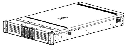
The servers come in the models listed in Table 39. These models support different drive configurations. For more information about drive configuration and compatible storage controller configuration, see "Drive configurations and numbering."
|
Model |
Maximum drive configuration |
|
8SFF |
24 SFF drives at the front. |
|
8LFF |
8 LFF drives at the front. |
|
12LFF |
12 LFF drives at the front + 4 LFF and 4SFF drives at the rear. |
|
25SFF |
25 SFF drives at the front + 2 LFF drives and 4 SFF drives at the rear. |
Technical specifications
|
Item |
8SFF |
8LFF |
12LFF |
25SFF |
|
Dimensions (H × W × D) |
· Without a security bezel: 87.5 × 445.5 × 748 mm (3.44 × 17.54 × 29.45 in) · With a security bezel: 87.5 × 445.5 × 771 mm (3.44 × 17.54 × 30.35 in) |
|||
|
Max. weight |
23.58 kg (51.99 lb) |
27.33 kg (60.25 lb) |
32.65 kg (71.98 lb) |
32.75 kg (72.20 lb) |
|
Processors |
2 × Intel Purley processors (Up to 3.8 GHz base frequency, maximum 205 W power consumption, and 38.5 MB cache per processor) |
|||
|
Memory |
24 × DIMMs |
|||
|
Chipset |
Intel C622 Lewisburg chipset |
|||
|
Network connection |
· 1 × onboard 1 Gbps HDM dedicated network port · 1 × mLOM Ethernet adapter connector |
|||
|
· 6 × USB connectors: ¡ 5 × USB 3.0 connectors (one at the server front, two at the server rear, and two on the system board) ¡ 1 × USB 2.0 connector (provided by the left chassis ear with a USB 2.0 connector) ¡ 1 × onboard mini-SAS connector (×8 SATA connectors) ¡ 1 × onboard ×1 SATA connector · 1 × RJ-45 HDM dedicated port at the server rear · 2 × VGA connectors (one at the server rear and one at the server front) · 1 × BIOS serial port at the server rear |
||||
|
Expansion slots |
10 × PCIe 3.0 modules (eight standard PCIe modules, one Mezzanine storage controller, and one Ethernet adapter) |
|||
|
Optical drives |
· External USB optical drives · Internal SATA optical drive The internal SATA optical drive is available only when the optical drive enablement option is installed. |
External USB optical drives |
External USB optical drives |
External USB optical drives |
|
Power supplies |
2 × hot-swappable power supplies in redundancy 550 W Platinum, 550 W high-efficiency Platinum, 800 W Platinum, 800 W –48 VDC, 800W 336V high-voltage DC, 850 W high-efficiency Platinum, 850 W Titanium, 1200 W Platinum, and 1600 W Platinum power supplies |
|||
|
Standards |
CCC SEPA |
|||
Components
Figure 269 Server components
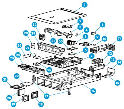
Table 40 Server components
|
Description |
|
|
(1) Access panel |
N/A |
|
(2) Power supply air baffle |
Provides ventilation aisles for power supplies. |
|
(3) Chassis-open alarm module |
Generates a chassis open alarm every time the access panel is removed. The alarms can be displayed from the HDM Web interface. |
|
(4) NVMe VROC module |
Works with VMD to provide RAID capability for the server to virtualize storage resources of NVMe drives. |
|
(5) Processor heatsink |
Cools the processor. |
|
(6) Processor |
Integrates a memory processing unit and a PCIe controller to provide data processing capabilities for the server. |
|
(7) System board |
One of the most important parts of a server, on which multiple components are installed, such as processor, memory, and fan. It is integrated with basic server components, including the BIOS chip, HDM chip, and PCIe connectors. |
|
(8) Dual SD card extended module |
Provides SD card slots. |
|
(9) Storage controller |
Provides RAID capability for the server to virtualize storage resources of SAS/SATA drives. It supports RAID configuration, RAID capability expansion, online upgrade, and remote configuration. |
|
(10) System battery |
Supplies power to the system clock. |
|
(11) Riser card |
Installed in the server to provide additional slots for PCIe modules. |
|
(12) Drive cage |
Encloses drives. |
|
(13) Power supply |
Supplies power to the server. It supports hot swapping and 1+1 redundancy. |
|
(14) Riser card blank |
Installed on an empty riser card connector to ensure good ventilation. |
|
(15) mLOM Ethernet adapter |
Installed on the mLOM Ethernet adapter connector of the system board for network expansion. |
|
(16) Chassis |
N/A |
|
(17) Chassis ears |
Attach the server to the rack. The right ear is integrated with the front I/O component. The left ear is available in two types: one with VGA and USB 2.0 connectors and one without connectors. |
|
(18) Serial label pull tab module |
Provides the device serial number, HDM default login settings, and document QR code. The module is available only for SFF server models. |
|
(19) Diagnostic panel |
Displays information about faulty components for quick diagnosis. The LFF diagnostic panel is integrated with a serial label pull tab that provides the HDM default login settings and document QR code. |
|
(20) Drive |
Drive for data storage, which is hot swappable. |
|
(21) M.2 transfer module |
Expands the server with a maximum of two SATA M.2 SSDs. |
|
(22) Optical drive |
Used for operating system installation and data backup. |
|
(23) Drive expander module |
Provides connection between drives and a storage controller to expand the number of drives controlled by the storage controller. If no drive expander module is installed, a storage controller can manage a maximum of eight drives. |
|
(24) Drive backplane |
Provides power and data channels for drives. |
|
(25) Supercapacitor holder |
Secures a supercapacitor in the chassis. |
|
(26) Memory |
Stores computing data and data exchanged with external storage. |
|
(27) Supercapacitor |
Supplies power to the flash card of the power fail safeguard module, which enables the storage controller to back up data to the flash card for protection when power outage occurs. |
|
(28) Fan blank |
Installed in an empty fan bay to ensure good ventilation. |
|
(29) Fan cage |
Used for holding fans. |
|
(30) Processor retaining bracket |
Attaches a processor to the heatsink. |
|
(31) Chassis air baffle |
Provides ventilation aisles for airflows in the chassis. |
|
(32) Fan |
Supports hot swapping and N+1 redundancy. |
Front panel
Front panel view
Figure 270, Figure 271, Figure 272, and Figure 273 show the front panel views of 8SFF, 25SFF, 8LFF, and 12LFF servers, respectively.
Figure 270 8SFF front panel
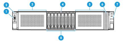
|
(1) VGA connector (optional) |
(2) USB 2.0 connector (optional) |
|
(3) Drive cage bay 1 for 8SFF NVMe SSDs, optical drives, or SATA M.2 SSDs |
|
|
(4) Serial label pull tab |
|
|
(5) Drive cage bay 3 for 8SFF SAS/SATA drives or 8SFF NVMe SSDs |
|
|
(6) Diagnostic panel or serial label pull tab module |
(7) USB 3.0 connector |
|
(8) Drive cage bay 2 for 8SFF SAS/SATA drives or 8SFF NVMe SSDs |
|
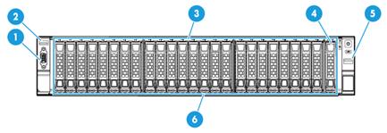
|
(1) VGA connector (optional) |
(2) USB 2.0 connector (optional) |
|
(3) Serial label pull tab |
(4) Diagnostic panel or serial label pull tab module |
|
(5) USB 3.0 connector |
(6) 25SFF drives |
Figure 272 8LFF front panel
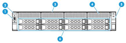
|
(1) VGA connector (optional) |
(2) USB 2.0 connector (optional) |
|
(3) Serial label pull tab |
(4) Diagnostic panel (optional) |
|
(5) USB 3.0 connector |
(6) 8LFF SAS/SATA drives |
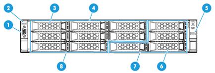
|
(1) VGA connector (optional) |
(2) USB 2.0 connector (optional) |
|
(3) Diagnostic panel (optional, applicable to the 8LFF SAS/SATA+4LFF NVMe drive configuration) |
|
|
(4) Serial label pull tab |
(5) USB 3.0 connector |
|
(6) Diagnostic panel (optional, applicable to the 12LFF SAS/SATA drive configuration) |
|
|
(7) SAS/SATA or NVMe drives |
(8) SAS/SATA drives |
LEDs and buttons
The LED and buttons are the same on all server models. Figure 274 shows the front panel LEDs and buttons. Table 41 describes the status of the front panel LEDs.
Figure 274 Front panel LEDs and buttons
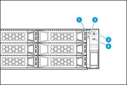
|
(1) Health LED |
(2) mLOM Ethernet adapter Ethernet port LED |
|
(3) Power on/standby button and system power LED |
(4) UID button LED |
Table 41 LEDs and buttons on the front panel
|
Button/LED |
Status |
|
Health LED |
· Steady green—The system is operating correctly, or a minor alarm has occurred. · Flashing green (4 Hz)—HDM is initializing. · Flashing amber (1 Hz)—A major alarm has occurred. · Flashing red (1 Hz)—A critical alarm has occurred. If a system alarm is present, log in to HDM to obtain more information about the system running status. |
|
mLOM Ethernet adapter Ethernet port LED |
· Steady green—A link is present on the port. · Flashing green (1 Hz)—The port is receiving or sending data. · Off—No link is present on the port. |
|
Power on/standby button and system power LED |
· Steady green—The system has started. · Flashing green (1 Hz)—The system is starting. · Steady amber—The system is in Standby state. · Off—No power is present. Possible reasons: ¡ No power source is connected. ¡ No power supplies are present. ¡ The installed power supplies are faulty. ¡ The system power cords are not connected correctly. |
|
UID button LED |
· Steady blue—UID LED is activated. The UID LED can be activated by using the following methods: ¡ Press the UID button LED. ¡ Activate the UID LED from HDM. · Flashing blue: ¡ 1 Hz—The firmware is being upgraded or the system is being managed from HDM. ¡ 4 Hz—HDM is restarting. To restart HDM, press the UID button LED for eight seconds. · Off—UID LED is not activated. |
Ports
The server does not provide fixed USB 2.0 or VGA connectors on its front panel. However, you can install a front media module if a USB 2.0 or VGA connection is needed, as shown in Table 42. For detailed port locations, see "Front panel view."
Table 42 Optional ports on the front panel
|
Port |
Type |
Description |
|
USB connector |
USB 3.0/2.0 |
Connects the following devices: · USB flash drive. · USB keyboard or mouse. · USB optical drive for operating system installation. |
|
VGA connector |
DB-15 |
Connects a display terminal, such as a monitor or KVM device. |
Rear panel
Rear panel view
Figure 275 shows the rear panel view.
Figure 275 Rear panel components
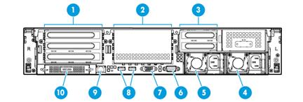
|
(1) PCIe slots 1 through 3 from the top down (processor 1) |
|
|
(2) PCIe slots 4 through 6 from the top down (processor 2) |
|
|
(3) PCIe slots 7 and 8 from the top down (processor 2) |
(4) Power supply 2 |
|
(5) Power supply 1 |
(6) BIOS serial port |
|
(7) VGA connector |
(8) USB 3.0 connectors |
|
(9) HDM dedicated network port (1 Gbps, RJ-45, default IP address 192.168.1.2/24) |
|
|
(10) PCIe slot 9 (mLOM Ethernet adapter, optional) |
|
LEDs
Figure 276 shows the rear panel LEDs. Table 43 describes the status of the rear panel LEDs.
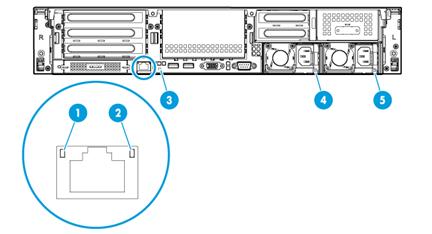
|
(1) Link LED of the Ethernet port |
(2) Activity LED of the Ethernet port |
|
(3) UID LED |
(4) Power supply 1 LED |
|
(5) Power supply 2 LED |
|
Table 43 LEDs on the rear panel
|
LED |
Status |
|
Link LED of the Ethernet port |
· Steady green—A link is present on the port. · Off—No link is present on the port. |
|
Activity LED of the Ethernet port |
· Flashing green (1 Hz)—The port is receiving or sending data. · Off—The port is not receiving or sending data. |
|
UID LED |
· Steady blue—UID LED is activated. The UID LED can be activated by using the following methods: ¡ Press the UID button LED. ¡ Enable UID LED from HDM. · Flashing blue: ¡ 1 Hz—The firmware is being updated or the system is being managed by HDM. ¡ 4 Hz—HDM is restarting. To restart HDM, press the UID button LED for eight seconds. · Off—UID LED is not activated. |
|
Power supply LED |
· Steady green—The power supply is operating correctly. · Flashing green (1 Hz)—Power is being input correctly but the system is not powered on. · Flashing green (0.33 Hz)—The power supply is in standby state and does not output power. · Flashing green (2 Hz)—The power supply is updating its firmware. · Steady amber—Either of the following conditions exists: ¡ The power supply is faulty. ¡ The power supply does not have power input, but the other power supply has correct power input. · Flashing amber (1 Hz)—An alarm has occurred on the power supply. · Off—No power supplies have power input, which can be caused by an incorrect power cord connection or power source shutdown. |
Ports
For detailed port locations, see "Rear panel view."
Table 44 Ports on the rear panel
|
Port |
Type |
Description |
|
HDM dedicated network port |
RJ-45 |
Establishes a network connection to manage HDM from its Web interface. |
|
USB connector |
USB 3.0 |
Connects the following devices: · USB flash drive. · USB keyboard or mouse. · USB optical drive for operating system installation. |
|
VGA connector |
DB-15 |
Connects a display terminal, such as a monitor or KVM device. |
|
BIOS serial port |
DB-9 |
The BIOS serial port is used for the following purposes: · Log in to the server when the remote network connection to the server has failed. · Establish a GSM modem or encryption lock connection. |
|
Power receptacle |
Standard single-phase |
Connects the power supply to the power source. |
System board
System board components
Figure 277 System board components

|
(1) TPM/TCM connector |
(2) Mezzanine storage controller connector (slot 10) |
|
(3) System battery |
(4) System maintenance switch 1 |
|
(5) System maintenance switch 2 |
(6) System maintenance switch 3 |
|
(7) PCIe riser connector 1 (processor 1) |
(8) mLOM Ethernet adapter connector (slot 9) |
|
(9) Ethernet adapter NCSI function connector |
(10) Mini-SAS port (×8 SATA ports) |
|
(11) Front I/O connector |
(12) Optical/SATA port |
|
(13) Diagnostic panel connector |
(14) Front drive backplane power connector 1 |
|
(15) Dual internal USB 3.0 connector |
(16) Front drive backplane AUX connector 2 or rear drive backplane AUX connector |
|
(17) Chassis-open alarm module, front VGA, and USB 2.0 connector |
(18) Front drive backplane power connector 2 and SATA M.2 SSD power connector |
|
(19) Front drive backplane AUX connector 1 |
(20) Rear drive backplane power connector |
|
(21) NVMe VROC module connector |
(22) PCIe riser connector 3 (processor 2) |
|
(23) Dual SD card extended module connector |
(24) PCIe riser connector 2 (processor 2) |
System maintenance switches
Use the system maintenance switches if you forget HDM username, HDM password, or BIOS password, or need to restore default BIOS settings, as described in Table 45. To identify the location of the switches on the system board, see Figure 277.
Table 45 System maintenance switches
|
Item |
Description |
Remarks |
|
System maintenance switch 1 |
· Pins 1-2 jumped (default)—HDM login requires the username and password of a valid HDM user account. · Pins 2-3 jumped—HDM login requires the default username and password. |
For security purposes, jump pins 1 and 2 after you complete tasks with the default username and password as a best practice. |
|
System maintenance switch 2 |
· Pins 1-2 jumped (default)—Normal server startup. · Pins 2-3 jumped—Clears all passwords from the BIOS at server startup. |
To clear all passwords from the BIOS, jump pins 2 and 3 and then start the server. All the passwords will be cleared from the BIOS. Before the next server startup, jump pins 1 and 2 to perform a normal server startup. |
|
System maintenance switch 3 |
· Pins 1-2 jumped (default)—Normal server startup. · Pins 2-3 jumped—Restores the default BIOS settings. |
To restore the default BIOS settings, jump pins 2 and 3 for over 30 seconds and then jump pins 1 and 2 for normal server startup. |
DIMM slots
The server provides 6 DIMM channels per processor, 12 channels in total. Each channel contains one white-coded slot and one black-coded slot, as shown in Table 46.
Table 46 DIMM slot numbering and color-coding scheme
|
Processor |
DlMM slots |
|
Processor 1 |
A1 through A6 (white coded) A7 through A12 (black coded) |
|
Processor 2 |
B1 through B6 (white coded) B7 through B12 (black coded) |
Figure 278 shows the physical layout of the DIMM slots on the system board. For more information about the DIMM slot population rules, see the guidelines in "Installing DIMMs."
Figure 278 DIMM physical layout
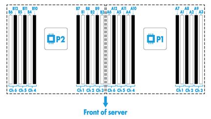
Appendix B Component specifications
This appendix provides information about hardware options available for the server at the time of this writing. The hardware options available for the server are subject to change over time. For the most up-to-date hardware options, consult your sales representative.
About component model names
The model name of a hardware option in this document might differ slightly from its model name label.
A model name label might add a prefix or suffix to the hardware-coded model name for purposes such as identifying the matching server brand or applicable region. For example, the DDR4-2666-8G-1Rx8-R memory model represents memory module labels including DDR4-2666-8G-1Rx8-R, DDR4-2666-8G-1Rx8-R-F, and DDR4-2666-8G-1Rx8-R-S, which have different suffixes.
Processors
Intel processors
Table 47 Skylake processors
|
Model |
Base frequency |
Power |
Number of cores |
Cache (L3) |
Supported max. data rate of DIMMs |
|
8168 |
2.7 GHz |
205 W |
24 |
33.00 MB |
2666 MHz |
|
8160 |
2.1 GHz |
150 W |
24 |
33.00 MB |
2666 MHz |
|
8158 |
3.0 GHz |
150 W |
12 |
24.75 MB |
2666 MHz |
|
8153 |
2.0 GHz |
125 W |
16 |
22.00 MB |
2666 MHz |
|
6154 |
3.0 GHz |
120 W |
18 |
24.75 MB |
2666 MHz |
|
6152 |
2.1 GHz |
140 W |
22 |
30.25 MB |
2666 MHz |
|
6150 |
2.7 GHz |
165 W |
18 |
24.75 MB |
2666 MHz |
|
6148 |
2.4 GHz |
150 W |
20 |
27.50 MB |
2666 MHz |
|
6146 |
3.2 GHz |
165 W |
12 |
24.75 MB |
2666 MHz |
|
6142 |
2.6 GHz |
150 W |
16 |
22.00 MB |
2666 MHz |
|
6140 |
2.3 GHz |
140 W |
18 |
24.75 MB |
2666 MHz |
|
6138 |
2.0 GHz |
125 W |
20 |
27.50 MB |
2666 MHz |
|
6136 |
3.0 GHz |
150 W |
12 |
24.75 MB |
2666 MHz |
|
6134 |
3.2 GHz |
130 W |
8 |
24.75 MB |
2666 MHz |
|
6132 |
2.6 GHz |
140 W |
14 |
19.25 MB |
2666 MHz |
|
6130 |
2.1 GHz |
125 W |
16 |
22.00 MB |
2666 MHz |
|
6128 |
3.4 GHz |
115 W |
6 |
19.25 MB |
2666 MHz |
|
6126 |
2.6 GHz |
125 W |
12 |
19.25 MB |
2666 MHz |
|
5122 |
3.6 GHz |
105 W |
4 |
16.50 MB |
2666 MHz |
|
5120 |
2.2 GHz |
105 W |
14 |
19.25 MB |
2400 MHz |
|
5118 |
2.3 GHz |
105 W |
12 |
16.50 MB |
2400 MHz |
|
5117 |
2.0 GHz |
105 W |
14 |
19.25 MB |
2400 MHz |
|
5115 |
2.4 GHz |
85 W |
10 |
13.75 MB |
2400 MHz |
|
4116 |
2.1 GHz |
85 W |
12 |
16.50 MB |
2400 MHz |
|
4114 |
2.2 GHz |
85 W |
10 |
13.75 MB |
2400 MHz |
|
4112 |
2.6 GHz |
85 W |
4 |
8.25 MB |
2400 MHz |
|
4110 |
2.1 GHz |
85 W |
8 |
11 MB |
2400 MHz |
|
4108 |
1.8 GHz |
85 W |
8 |
11 MB |
2400 MHz |
|
3106 |
1.7 GHz |
85 W |
8 |
11 MB |
2133 MHz |
|
3104 |
1.7 GHz |
85 W |
6 |
8.25 MB |
2133 MHz |
Table 48 Cascade Lake processors
|
Model |
Base frequency |
Power |
Number of cores |
Cache (L3) |
Supported max. data rate of DIMMs |
|
8276 |
2.2 GHz |
165 W |
28 |
38.50 MB |
2933 |
|
8260 |
2.4 GHz |
165 W |
24 |
35.75 MB |
2933 |
|
6254 |
3.1 GHz |
200 W |
18 |
24.75 MB |
2933 |
|
6248 |
2.5 GHz |
150 W |
20 |
27.50 MB |
2933 |
|
6244 |
3.6 GHz |
150 W |
8 |
24.75 MB |
2933 |
|
6240 |
2.6 GHz |
150 W |
18 |
24.75 MB |
2933 |
|
6230 |
2.3 GHz |
125 W |
20 |
27.50 MB |
2933 |
|
5220 |
2.2 GHz |
125 W |
18 |
24.75 MB |
2666 |
|
5220S |
2.7 GHz |
125 W |
18 |
24.75 MB |
2666 |
|
5217 |
3.0 GHz |
115 W |
8 |
24.75 MB |
2667 |
|
5218 |
2.3 GHz |
110 W |
16 |
22 MB |
2666 |
|
4214 |
2.2 GHz |
85 W |
12 |
16.50 MB |
2400 |
|
4215 |
2.5 GHz |
85 W |
8 |
11 MB |
2666 |
|
4216 |
2.1 GHz |
100 W |
16 |
24.75 MB |
2400 |
|
5215 |
2.5 GHz |
85 W |
10 |
13.75 MB |
2666 |
|
5217 |
3.0 GHz |
115 W |
8 |
24.75 MB |
2667 |
|
6234 |
3.3 GHz |
130 W |
8 |
24.75 MB |
2933 |
|
6252 |
2.1 GHz |
150 W |
24 |
33 MB |
2933 |
|
8253 |
2.2 GHz |
125 W |
16 |
22 MB |
2933 |
|
3204 |
1.9 GHz |
85 W |
6 |
13.75 MB |
2133 |
|
4208 |
2.1 GHz |
85 W |
8 |
13.75 MB |
2400 |
|
4210 |
2.2 GHz |
85 W |
10 |
13.75 MB |
2400 |
|
5222 |
3.8 GHz |
105 W |
4 |
16.50 MB |
3800 |
|
6222 |
1.8 GHz |
125 W |
20 |
27.50 MB |
2400 |
|
6238 |
2.1 GHz |
140 W |
22 |
30.25 MB |
2933 |
|
6246 |
3.3 GHz |
165 W |
12 |
24.75 MB |
2933 |
|
8256 |
3.8 GHz |
105 W |
4 |
16.50 MB |
3800 |
|
6240Y |
2.6 GHz |
150 W |
18 |
24.75 MB |
2933 |
DIMMs
The server provides 6 DIMM channels per processor, 12 channels in total. Each DIMM channel has two DIMM slots and supports a maximum of eight ranks. For the physical layout of DIMM slots, see "DIMM slots."
DRAM specifications
|
Product code |
Model |
Type |
Capacity |
Data rate |
Rank |
|
0231A6SP |
DDR4-2666-16G-1Rx4-R |
RDIMM |
16 GB |
2666 MHz |
Single-rank |
|
0231AADP |
DDR4-2666-16G-1Rx4-R-1 |
RDIMM |
16 GB |
2666 MHz |
Single-rank |
|
0231AAEF |
DDR4-2666-16G-1Rx4-R-2 |
RDIMM |
16 GB |
2666 MHz |
Single-rank |
|
0231AAEG |
DDR4-2666-16G-1Rx4-R-3 |
RDIMM |
16 GB |
2666 MHz |
Single-rank |
|
0231A6SS |
DDR4-2666-32G-2Rx4-R |
RDIMM |
32 GB |
2666 MHz |
Dual-rank |
|
0231AAE9 |
DDR4-2666-32G-2Rx4-R-1 |
RDIMM |
32 GB |
2666 MHz |
Dual-rank |
|
0231AAEJ |
DDR4-2666-32G-2Rx4-R-2 |
RDIMM |
32 GB |
2666 MHz |
Dual-rank |
|
0231AAEK |
DDR4-2666-32G-2Rx4-R-3 |
RDIMM |
32 GB |
2666 MHz |
Dual-rank |
|
0231A8QJ |
DDR4-2666-64G-4Rx4-L |
LRDIMM |
64 GB |
2666 MHz |
Quad-rank |
|
0231AADQ |
DDR4-2666-64G-4Rx4-L-1 |
LRDIMM |
64 GB |
2666 MHz |
Quad-rank |
|
0231AADT |
DDR4-2666-64G-4Rx4-L-2 |
LRDIMM |
64 GB |
2666 MHz |
Quad-rank |
|
0231AADR |
DDR4-2666-64G-4Rx4-L-3 |
LRDIMM |
64 GB |
2666 MHz |
Quad-rank |
|
0231AC4S |
DDR4-2933P-16G-1Rx4-R |
RDIMM |
16 GB |
2933 MHz |
Single-rank |
|
0231AC4V |
DDR4-2933P-16G-2Rx8-R |
RDIMM |
16 GB |
2933 MHz |
Dual-rank |
|
0231AC4T |
DDR4-2933P-32G-2Rx4-R |
RDIMM |
32 GB |
2933 MHz |
Dual-rank |
|
0231AC4N |
DDR4-2933P-64G-2Rx4-R |
RDIMM |
64 GB |
2933 MHz |
Dual-rank |
DCPMM specifications
|
Product code |
Model |
Type |
Capacity |
Data rate |
|
0231AC5R |
AP-128G-NMA1XBD128GQSE |
Apache Pass |
128 GB |
2666 MHz |
|
0231AC7P |
AP-256G-NMA1XBD256GQSE |
Apache Pass |
256 GB |
2666 MHz |
|
0231AC65 |
AP-512G-NMA1XBD512GQSE |
Apache Pass |
512 GB |
2666 MHz |
DIMM rank classification label
A DIMM rank is a set of memory chips that the system accesses while writing or reading from the memory. On a multi-rank DIMM, only one rank is accessible at a time.
To determine the rank classification of a DIMM, use the label attached to the DIMM, as shown in Figure 279.
Figure 279 DIMM rank classification label
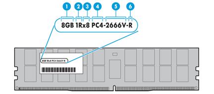
Table 49 DIMM rank classification label description
|
Callout |
Description |
Remarks |
|
1 |
Capacity |
N/A |
|
2 |
Number of ranks |
N/A |
|
3 |
Data width |
· ×4—4 bits. · ×8—8 bits. |
|
4 |
DIMM generation |
Only DDR4 is supported. |
|
5 |
Data rate |
· 2133P—2133 MHz. · 2400T—2400 MHz. · 2666V—2666 MHz. · 2933Y—2933 MHz. |
|
6 |
DIMM type |
· L—LRDIMM. · R—RDIMM. |
HDDs and SSDs
Drive specifications
SAS HDDs
|
Model |
Form factor |
Capacity |
Rate |
Rotating speed |
|
HDD-600G-SAS-12G-15K-SFF-1 |
SFF |
600 GB |
12 Gbps |
15000 RPM |
|
HDD-900G-SAS-12G-15K-SFF |
SFF |
900 GB |
12 Gbps |
15000 RPM |
|
HDD-1.2T-SAS-12G-10K-SFF |
SFF |
1.2 TB |
12 Gbps |
10000 RPM |
|
HDD-1.8T-SAS-12G-10K-SFF |
SFF |
1.8 TB |
12 Gbps |
10000 RPM |
|
HDD-2.4T-SAS-12G-10K-SFF |
SFF |
2.4 TB |
12 Gbps |
10000 RPM |
|
HDD-600G-SAS-12G-10K-LFF |
LFF |
600 GB |
12 Gbps |
10000 RPM |
|
HDD-600G-SAS-12G-15K-LFF-1 |
LFF |
600 GB |
12 Gbps |
15000 RPM |
|
HDD-900G-SAS-12G-15K-LFF |
LFF |
900 GB |
12 Gbps |
15000 RPM |
|
HDD-2T-SAS-12G-7.2K-LFF |
LFF |
2 TB |
12 Gbps |
7200 RPM |
|
HDD-2.4T-SAS-12G-10K-LFF |
LFF |
2.4 TB |
12 Gbps |
10000 RPM |
|
HDD-6T-SAS-12G-7.2K-LFF |
LFF |
6 TB |
12 Gbps |
7200 RPM |
|
HDD-10T-SAS-12G-7.2K-LFF |
LFF |
10 TB |
12 Gbps |
7200 RPM |
|
HDD-300G-SAS-12G-15K-EP-SFF |
LFF |
300 GB |
12 Gbps |
15000 RPM |
|
HDD-300G-SAS-12G-15K-EP-SCL |
LFF |
300 GB |
12 Gbps |
15000 RPM |
|
HDD-600G-SAS-12G-10K-SFF |
LFF |
600 GB |
12 Gbps |
10000 RPM |
|
HDD-300G-SAS-12G-10K-EP-SFF |
LFF |
300 GB |
12 Gbps |
10000 RPM |
|
HDD-300G-SAS-12G-10K-EP-SCL |
LFF |
300 GB |
12 Gbps |
10000 RPM |
|
HDD-1.2T-SAS-12G-10K-LFF |
LFF |
1.2 TB |
12 Gbps |
10000 RPM |
|
HDD-1.8T-SAS-12G-10K-LFF |
LFF |
1.8 TB |
12 Gbps |
10000 RPM |
|
HDD-8T-SAS-12G-7.2K-LFF-1 |
LFF |
8 TB |
12 Gbps |
7200 RPM |
SATA HDDs
|
Model |
Form factor |
Capacity |
Rate |
Rotating speed |
|
HDD-1T-SATA-6G-7.2K-SFF-1 |
SFF |
1 TB |
6 Gbps |
7200 RPM |
|
HDD-2T-SATA-6G-7.2K-SFF |
SFF |
2 TB |
6 Gbps |
7200 RPM |
|
HDD-1T-SATA-6G-7.2K-LFF-1 |
LFF |
1 TB |
6 Gbps |
7200 RPM |
|
HDD-2T-SATA-6G-7.2K-LFF-1 |
LFF |
2 TB |
6 Gbps |
7200 RPM |
|
HDD-4T-SATA-6G-7.2K-LFF |
LFF |
4 TB |
6 Gbps |
7200 RPM |
|
HDD-6T-SATA-6G-7.2K-LFF |
LFF |
6 TB |
6 Gbps |
7200 RPM |
|
HDD-8T-SATA-6G-7.2K-LFF-3 |
LFF |
8 TB |
6 Gbps |
7200 RPM |
|
HDD-10T-SATA-6G-7.2K-LFF-1 |
LFF |
10 TB |
6 Gbps |
7200 RPM |
|
HDD-12T-SATA-6G-7.2K-LFF |
LFF |
12 TB |
6 Gbps |
7200 RPM |
|
HDD-14T-SATA-6G-7.2K-LFF |
LFF |
14 TB |
6 Gbps |
7200 RPM |
SATA SSDs
|
Model |
Vendor |
Form factor |
Capacity |
Rate |
|
SSD-240G-SATA-6G-EM-SFF-i-2 |
Intel |
SFF |
240 GB |
6 Gbps |
|
SSD-240G-SATA-6G-EV-SFF-i-1 |
Intel |
SFF |
240 GB |
6 Gbps |
|
SSD-480G-SATA-6G-SFF-2 |
Micron |
SFF |
480 GB |
6 Gbps |
|
SSD-480G-SATA-6G-EV-SFF-i-2 |
Intel |
SFF |
480 GB |
6 Gbps |
|
SSD-480G-SATA-6G-EM-SFF-i-3 |
Intel |
SFF |
480 GB |
6 Gbps |
|
SSD-480G-SATA-6G-EV-SFF-sa |
Samsung |
SFF |
480 GB |
6 Gbps |
|
SSD-480G-SATA-Ny1351-SFF-6 |
Seagate |
SFF |
480 GB |
6 Gbps |
|
SSD-960G-SATA-6G-SFF-2 |
Micron |
SFF |
960 GB |
6 Gbps |
|
SSD-960G-SATA-6G-EM-SFF-m |
Micron |
SFF |
960 GB |
6 Gbps |
|
SSD-960G-SATA-6G-EV-SFF-i |
Intel |
SFF |
960 GB |
6 Gbps |
|
SSD-960G-SATA-6G-EM-SFF-i-2 |
Intel |
SFF |
960 GB |
6 Gbps |
|
SSD-960G-SATA-Ny1351-SFF-7 |
Seagate |
SFF |
960 GB |
6 Gbps |
|
SSD-960G-SATA-PM883-SFF |
Samsung |
SFF |
960 GB |
6 Gbps |
|
SSD-1.92T-SATA-6G-EM-SFF-i-1 |
Intel |
SFF |
1.92 TB |
6 Gbps |
|
SSD-1.92T-SATA-6G-SFF-3 |
Micron |
SFF |
1.92 TB |
6 Gbps |
|
SSD-1.92T-SATA-6G-EM-SFF-m |
Micron |
SFF |
1.92 TB |
6 Gbps |
|
SSD-1.92T-SATA-6G-EV-SFF-i |
Intel |
SFF |
1.92 TB |
6 Gbps |
|
SSD-1.92T-SATA-PM883-SFF |
Samsung |
SFF |
1.92 TB |
6 Gbps |
|
SSD-3.84T-SATA-6G-EM-SFF-i |
Intel |
SFF |
3.84 TB |
6 Gbps |
|
SSD-3.84T-SATA-6G-EV-SFF-i |
Intel |
SFF |
3.84 TB |
6 Gbps |
|
SSD-3.84T-SATA-6G-SFF |
Micron |
SFF |
3.84 TB |
6 Gbps |
|
SSD-3.84T-SATA-PM883-SFF |
Samsung |
SFF |
3.84 TB |
6 Gbps |
|
SSD-240G-SATA-6G-EV-SCL-i |
Intel |
LFF |
240 GB |
6 Gbps |
|
SSD-240G-SATA-6G-EM-SCL-i-1 |
Intel |
LFF |
240 GB |
6 Gbps |
|
SSD-480G-SATA-6G-EV-SCL-i-1 |
Intel |
LFF |
480 GB |
6 Gbps |
|
SSD-480G-SATA-6G-EM-SCL-i-2 |
Intel |
LFF |
480 GB |
6 Gbps |
|
SSD-480G-SATA-6G-EV-SCL-sa |
Samsung |
LFF |
480 GB |
6 Gbps |
|
SSD-960G-SATA-6G-EM-SCL-m |
Micron |
LFF |
960 GB |
6 Gbps |
|
SSD-960G-SATA-6G-EV-SCL-i |
Intel |
LFF |
960 GB |
6 Gbps |
|
SSD-960G-SATA-6G-EM-SCL-i |
Intel |
LFF |
960 GB |
6 Gbps |
|
SSD-960G-SATA-6G-LFF |
Samsung |
LFF |
960 GB |
6 Gbps |
|
SSD-960G-SATA-PM883-SCL |
Samsung |
LFF |
960 GB |
6 Gbps |
|
SSD-1.92T-SATA-6G-EM-SCL-i |
Intel |
LFF |
1.92 TB |
6 Gbps |
|
SSD-1.92T-SATA-6G-EM-SCL-m |
Micron |
LFF |
1.92 TB |
6 Gbps |
|
SSD-1.92T-SATA-6G-EV-SCL-i |
Intel |
LFF |
1.92 TB |
6 Gbps |
|
SSD-1.92T-SATA-6G-LFF-3 |
Micron |
LFF |
1.92 TB |
6 Gbps |
|
SSD-1.92T-SATA-PM883-SCL |
Samsung |
LFF |
1.92 TB |
6 Gbps |
|
SSD-3.84T-SATA-6G-LFF-3 |
Micron |
LFF |
3.84 TB |
6 Gbps |
|
SSD-3.84T-SATA-6G-EM-SCL-i |
Intel |
LFF |
3.84 TB |
6 Gbps |
|
SSD-3.84T-SATA-6G-EV-SCL-i |
Intel |
LFF |
3.84 TB |
6 Gbps |
|
SSD-3.84T-SATA-PM883-SCL |
Samsung |
LFF |
3.84 TB |
6 Gbps |
SAS SSDs
|
Model |
Vendor |
Form factor |
Capacity |
Rate |
|
SSD-400G-SAS3-SS530-SFF |
WD |
LFF |
400 GB |
12 Gbps |
|
SSD-400G-SAS3-SS530-SCL |
WD |
LFF |
400 GB |
12 Gbps |
|
800G-SAS3-SS530-SFF |
WD |
LFF |
800 GB |
12 Gbps |
|
800G-SAS3-SS530-SCL |
WD |
LFF |
800 GB |
12 Gbps |
|
3.2T-SAS3-SS530-SFF |
WD |
LFF |
3.2 TB |
12 Gbps |
|
3.2T-SAS3-SS530-SCL |
WD |
LFF |
3.2 TB |
12 Gbps |
SAS-3 SSDs
|
Model |
Vendor |
Form factor |
Capacity |
Rate |
|
1.6T-SAS3-SS530-SFF |
WD |
LFF |
1.6 TB |
12 Gbps |
|
1.6T-SAS3-SS530-SCL |
WD |
LFF |
1.6 TB |
12 Gbps |
NVMe SSDs
|
Model |
Vendor |
Form factor |
Capacity |
Interface |
Rate |
|
SSD-375G-NVMe-SFF-i |
Intel |
SFF |
375 GB |
PCIe |
8 Gbps |
|
SSD-750G-NVMe-SFF-i |
Intel |
SFF |
750 GB |
PCIe |
8 Gbps |
|
SSD-960G-NVMe-EV-SFF-sa |
Samsung |
SFF |
960 GB |
PCIe |
8 Gbps |
|
SSD-960G-NVMe-SFF-1 |
HGST |
SFF |
960 GB |
PCIe |
8 Gbps |
|
SSD-1T-NVMe-SFF-i-1 |
Intel |
SFF |
1 TB |
PCIe |
8 Gbps |
|
SSD-1.6T-NVMe-EM-SFF-i |
Intel |
SFF |
1.6 TB |
PCIe |
8 Gbps |
|
SSD-1.92T-NVMe-EV-SFF-sa |
Samsung |
SFF |
1.92 TB |
PCIe |
8 Gbps |
|
SSD-2T-NVMe-SFF-i-1 |
Intel |
SFF |
2 TB |
PCIe |
8 Gbps |
|
SSD-3.2T-NVMe-EM-SFF-mbl |
Memblaze |
SFF |
3.2 TB |
PCIe |
8 Gbps |
|
SSD-3.2T-NVMe-EM-SFF-i |
Intel |
SFF |
3.2 TB |
PCIe |
8 Gbps |
|
SSD-4T-NVMe-SFF-i-2 |
Intel |
SFF |
4 TB |
PCIe |
8 Gbps |
|
SSD-3.2T-NVMe-SFF-2 |
HGST |
SFF |
3.2 TB |
PCIe |
8 Gbps |
|
SSD-3.84T-NVMe-SFF-1 |
HGST |
SFF |
3.84 TB |
PCIe |
8 Gbps |
|
SSD-3.84T-NVMe-EV-SFF-sa |
Samsung |
SFF |
3.84 TB |
PCIe |
8 Gbps |
|
SSD-6.4T-NVMe-SFF-1 |
HGST |
SFF |
6.4 TB |
PCIe |
8 Gbps |
|
SSD-6.4T-NVMe-EM-SFF-mbl |
Memblaze |
SFF |
6.4 TB |
PCIe |
8 Gbps |
|
SSD-6.4T-NVMe-EM-SFF-i |
Intel |
SFF |
6.4 TB |
PCIe |
8 Gbps |
|
SSD-7.68T-NVMe-EM-SFF-i |
Intel |
SFF |
7.68 TB |
PCIe |
8 Gbps |
|
SSD-8T-NVMe-SFF-i |
Intel |
SFF |
8 TB |
PCIe |
8 Gbps |
|
SSD-375G-NVMe-LFF-i |
Intel |
LFF |
375 GB |
PCIe |
8 Gbps |
|
SSD-750G-NVMe-LFF-i |
Intel |
LFF |
750G |
PCIe |
8 Gbps |
|
SSD-960G-NVMe-EV-SCL-sa |
Samsung |
LFF |
960G |
PCIe |
8 Gbps |
|
SSD-960G-NVMe-LFF-1 |
HGST |
LFF |
960G |
PCIe |
8 Gbps |
|
SSD-1T-NVMe-LFF-i-1 |
Intel |
LFF |
1 TB |
PCIe |
8 Gbps |
|
SSD-1.6T-NVMe-EM-SCL-i |
Intel |
LFF |
1.6 TB |
PCIe |
8 Gbps |
|
SSD-1.92T-NVMe-EV-SCL-sa |
Samsung |
LFF |
1.92 TB |
PCIe |
8 Gbps |
|
SSD-2T-NVMe-LFF-i |
Intel |
LFF |
2 TB |
PCIe |
8 Gbps |
|
SSD-3.2T-NVMe-EM-SCL-mbl |
Memblaze |
LFF |
3.2 TB |
PCIe |
8 Gbps |
|
SSD-3.2T-NVMe-EM-SCL-i |
Intel |
LFF |
3.2 TB |
PCIe |
8 Gbps |
|
SSD-3.2T-NVMe-LFF-2 |
HGST |
LFF |
3.2 TB |
PCIe |
8 Gbps |
|
SSD-3.84T-NVMe-LFF-1 |
HGST |
LFF |
3.84 TB |
PCIe |
8 Gbps |
|
SSD-3.84T-NVMe-EV-SCL-sa |
Samsung |
LFF |
3.84 TB |
PCIe |
8 Gbps |
|
SSD-4T-NVMe-LFF-i |
Intel |
LFF |
4 TB |
PCIe |
8 Gbps |
|
SSD-6.4T-NVMe-LFF-1 |
HGST |
LFF |
6.4 TB |
PCIe |
8 Gbps |
|
SSD-6.4T-NVMe-EM-SCL-mbl |
Memblaze |
LFF |
6.4 TB |
PCIe |
8 Gbps |
|
SSD-6.4T-NVMe-EM-SCL-i |
Intel |
LFF |
6.4 TB |
PCIe |
8 Gbps |
|
SSD-7.68T-NVMe-EM-SCL-i |
Intel |
LFF |
7.68 TB |
PCIe |
8 Gbps |
|
SSD-8T-NVMe-LFF-i |
Intel |
LFF |
8 TB |
PCIe |
8 Gbps |
|
SSD-1.5T-NVMe-P4800X-SFF |
Intel |
LFF |
1.5 TB |
PCIe |
8 Gbps |
|
SSD-1.5T-NVMe-P4800X-SCL |
Intel |
LFF |
1.5 TB |
PCIe |
8 Gbps |
SATA M.2 SSDs
|
Model |
Dimensions |
Capacity |
Interface |
Rate |
|
SSD-240G-SATA-S4510-M.2 |
M.2 2280: 80 × 22 mm (3.15 × 0.87 in) |
240 GB |
SATA |
6 Gbps |
|
SSD-240G-SATA-M2 |
M.2 2280: 80 × 22 mm (3.15 × 0.87 in) |
240 GB |
SATA |
6 Gbps |
|
SSD-480G-SATA-M2 |
M.2 2280: 80 × 22 mm (3.15 × 0.87 in) |
480 GB |
SATA |
6 Gbps |
|
SSD-480G-SATA-5100ECO-M.2 |
M.2 2280: 80 × 22 mm (3.15 × 0.87 in) |
480 GB |
SATA |
6 Gbps |
|
SSD-480G-SATA-S4510-M.2 |
M.2 2280: 80 × 22 mm (3.15 × 0.87 in) |
480 GB |
SATA |
6 Gbps |
NVMe SSD PCIe accelerator module
|
Model |
Vendor |
Form factor |
Capacity |
Interface |
Rate |
Link width |
|
SSD-NVME-375G-P4800X |
Intel |
HHHL |
375 GB |
PCIe |
8 Gbps |
×4 |
|
SSD-NVME-750G-P4800X |
Intel |
HHHL |
750 GB |
PCIe |
8 Gbps |
×4 |
|
SSD-1.6T-NVME-PB516 |
Memblaze |
HHHL |
1.6 TB |
PCIe |
8 Gbps |
×8 |
|
SSD-NVME-3.2T-PBlaze5 |
Memblaze |
HHHL |
3.2 TB |
PCIe |
8 Gbps |
×8 |
|
SSD-NVME-6.4T-PBlaze5 |
Memblaze |
HHHL |
6.4 TB |
PCIe |
8 Gbps |
×8 |
Drive LEDs
The server supports SAS, SATA, and NVMe drives, of which SAS and SATA drives support hot swapping and NVMe drives support hot insertion and managed hot removal. You can use the LEDs on a drive to identify its status after it is connected to a storage controller.
Figure 280 shows the location of the LEDs on a drive.
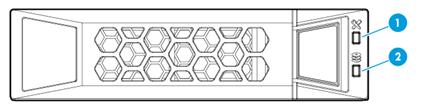
|
(1) Fault/UID LED |
(2) Present/Active LED |
To identify the status of a SAS or SATA drive, use Table 50. To identify the status of an NVMe drive, use Table 51.
Table 50 SAS/SATA drive LED description
|
Fault/UID LED status |
Present/Active LED status |
Description |
|
Flashing amber (0.5 Hz) |
Steady green/Flashing green (4.0 Hz) |
A drive failure is predicted. As a best practice, replace the drive before it fails. |
|
Steady amber |
Steady green/Flashing green (4.0 Hz) |
The drive is faulty. Replace the drive immediately. |
|
Steady blue |
Steady green/Flashing green (4.0 Hz) |
The drive is operating correctly and is selected by the RAID controller. |
|
Off |
Flashing green (4.0 Hz) |
The drive is performing a RAID migration or rebuilding, or the system is reading or writing data to the drive. |
|
Off |
Steady green |
The drive is present but no data is being read or written to the drive. |
|
Off |
Off |
The drive is not securely installed. |
Table 51 NVMe drive LED description
|
Fault/UID LED status |
Present/Active LED status |
Description |
|
Flashing amber (0.5 Hz) |
Off |
The managed hot removal process is completed. You can remove the drive safely. |
|
Flashing amber (4.0 Hz) |
Off |
The drive is in hot insertion process. |
|
Steady amber |
Steady green/Flashing green (4.0 Hz) |
The drive is faulty. Replace the drive immediately. |
|
Steady blue |
Steady green/Flashing green (4.0 Hz) |
The drive is operating correctly and selected by the RAID controller. |
|
Off |
Flashing green (4.0 Hz) |
The drive is performing a RAID migration or rebuilding, or the system is reading or writing data to the drive. |
|
Off |
Steady green |
The drive is present but no data is being read or written to the drive. |
|
Off |
Off |
The drive is not securely installed. |
Drive configurations and numbering
Unless otherwise specified, the term "standard" in tables Table 52, Table 54, Table 56, and Table 57 refers to a standard storage controller with 8 internal SAS ports, the RAID-LSI-9361-8i(1G)-A1-X for example.
8SFF server
Table 52 presents the drive configurations available for the 8SFF server and their compatible types of storage controllers and NVMe SSD expander modules.
These drive configurations use different drive cage bays and drive numbering schemes, as shown in Table 53.
Table 52 Drive, storage controller, and NVMe SSD expander module configurations (8SFF server)
|
Drive backplane and drive expander module |
Drive configuration |
Storage controller |
NVMe SSD expander module |
|
Front 8SFF drive cage module |
8SFF (8 front SFF SAS/SATA drives in drive cage bay 2) |
· Embedded RSTe · Mezzanine · Standard in PCIe slot 2 or 6 |
N/A |
|
16SFF (16 front SFF SAS/SATA drives in drive cage bays 2 and 3) |
· Mezzanine + standard in PCIe slot 6 · Standard controller RAID-LSI-9460-16i(4G) in PCIe slot 6 · Standard in PCIe slot 3 + standard in PCIe slot 6 |
N/A |
|
|
16SFF (8 front SFF SAS/SATA drives in drive cage bay 2 + 8 front SFF NVMe drives in drive cage bay 3) |
Embedded RSTe |
· 1 × 8-port NVMe SSD expander module in PCIe slot 2 · 2 × 4-port NVMe SSD expander modules in PCIe slots 2 and 5 |
|
|
Mezzanine |
· 2 × 4-port NVMe SSD expander modules in PCIe slots 2 and 5 · 1 × 8-port NVMe SSD expander module in PCIe slot 2 |
||
|
Standard in PCIe slot 6 |
· 1 × 8-port NVMe SSD expander module in PCIe slot 2 · 2 × 4-port NVMe SSD expander modules in PCIe slots 2 and 5 |
||
|
24SFF (16 front SFF SAS/SATA drives in drive cage bays 1 and 2 + 8 front SFF NVMe drives in drive cage bay 3) |
· Standard controller RAID-LSI-9460-16i(4G) in PCIe slot 6 · Mezzanine + standard in PCIe slot 6 |
1 × 8-port NVMe SSD expander module in PCIe slot 2 |
|
|
8SFF (8 front SFF NVMe drives in drive cage bay 2) |
Standard in PCIe slot 6 + standard in PCIe slot 8 |
· 1 × 4-port NVMe SSD expander module in PCIe slot 2 + 1 × 4-port NVMe SSD expander module in PCIe slot 5 |
|
|
24SFF (16 front SFF SAS/SATA drives in drive cage bays 1 and 2 + 8 front SFF SAS/SATA drives in drive cage bay 3) |
Standard in PCIe slot 5 + standard controller RAID-LSI-9460-16i(4G) in PCIe slot 6 |
N/A |
|
|
8SFF (8 front SFF NVMe drives in drive cage bay 2) 16SFF (16 front SFF NVMe drives in drive cage bays 2 and 3) 24SFF (8 front SFF SAS/SATA drives in drive cage bay 1 + 16 front SFF NVMe drives in drive cage bays 2 and 3) |
N/A |
· 1 × 8-port NVMe SSD expander module in PCIe slot 2 2 × 4-port NVMe SSD expander modules in PCIe slots 2 and 5 |
|
|
N/A |
2 × 8-port NVMe SSD expander modules in PCIe slots 2 and 5 |
||
|
Embedded RSTe |
2 × 8-port NVMe SSD expander modules in PCIe slots 2 and 5 |
||
|
24SFF (24 front SFF NVMe drives) |
Mezzanine |
2 × 8-port NVMe SSD expander modules in PCIe slots 2 and 5 |
|
|
|
|
Standard |
2 × 8-port NVMe SSD expander modules in PCIe slots 2 and 5 |
|
|
NOTE: Front 8SFF drive cage modules include front 8SFF NVMe drive cage modules and front 8SFF NVMe drive cage modules. For more information about SAS/SATA and NVMe drive cage modules, see "Expander modules." |
Table 53 Drive population and drive numbering schemes (8SFF server)
|
Drive configuration |
Drive cage bay 1 |
Drive cage bay 2 |
Drive cage bay 3 |
Drive numbering |
|
8SFF |
Unused |
Used |
Unused |
See Figure 281. |
|
16SFF |
Unused |
Used |
Used |
See Figure 282. |
|
24SFF |
Used |
Used |
Used |
See Figure 283 and Figure 284. |
|
|
NOTE: For the location of the drive cage bays on the front panel of the server, see "Front panel view." |
Figure 281 Drive numbering for 8SFF drive configurations (8SFF server)
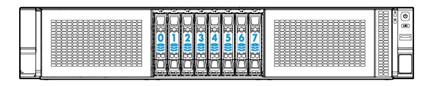
Figure 282 Drive numbering for 16SFF drive configurations (8SFF server)
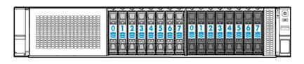
Figure 283 Drive numbering for the 24SFF drive configuration (8SFF server)
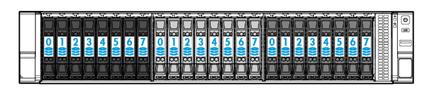
Figure 284 Drive numbering for the 24SFF NVMe drive configuration (8SFF server)
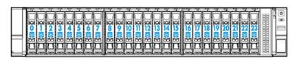
25SFF server
Table 54 presents the drive configurations available for the 25SFF server and their compatible types of storage controllers and NVMe SSD expander modules.
Table 54 Drive, storage controller, and NVMe SSD expander module configurations (25SFF server)
|
Drive backplane and drive expander module |
Drive configuration |
Storage controller |
NVMe SSD expander module |
|
BP-25SFF-R4900 25SFF drive backplane + drive expander module |
25SFF (25 front SFF SAS/SATA drives) |
· Mezzanine · Standard in PCIe slot 2 |
N/A |
|
27SFF (25 front SFF and 2 rear SFF SAS/SATA drives) |
· Mezzanine · Standard in PCIe slot 2 The rear drives must be connected to the drive expander module. |
N/A |
|
|
29SFF (25 front SFF and 4 rear SFF SAS/SATA drives) |
· Mezzanine · Standard in PCIe slot 2 The rear drives must be connected to the drive expander module. |
N/A |
|
|
29SFF+2LFF (25 front and 4 rear SFF SAS/SATA drives + 2 rear LFF SAS/SATA drives) |
· Mezzanine · Standard in PCIe slot 2 The rear drives must be connected to the drive expander module. |
N/A |
|
|
BP2-25SFF-2U-G3 25SFF drive backplane |
25SFF (25 front SFF SAS/SATA drives) |
· Mezzanine · Standard in PCIe slot 6 |
N/A |
|
27SFF (25 front SFF SAS/SATA drives + 2 rear SFF SAS/SATA drives) |
· Mezzanine · Standard in PCIe slot 6 The rear drives must be connected to the drive backplane. |
N/A |
|
|
NOTE: The BP2-25SFF-2U-G3 25SFF drive backplane provides the function of a drive expander module and can be used without any drive expander module. |
These drive configurations use different drive numbering schemes, as shown in Table 55.
Table 55 Drive numbering schemes (25SFF server)
|
Drive configuration |
Drive numbering |
|
25SFF (25 SFF front drives) |
See Figure 285. |
|
27SFF (25 SFF front drives and 2 SFF rear drives) |
See Figure 286. |
|
29SFF (25 SFF front drives and 4 SFF rear drives) |
See Figure 287. |
|
29SFF+2LFF (25 SFF front drives, 4 SFF rear drives, and 2 LFF rear drives) |
See Figure 288. |
Figure 285 Drive numbering for the 25SFF configuration (25SFF server)
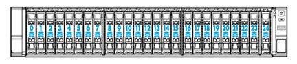
Figure 286 Drive numbering for the 27SFF (25 front+2 rear) drive configuration (25SFF server)
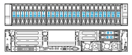
Figure 287 Drive numbering for the 29SFF (25 front+4 rear) drive configuration (25SFF server)
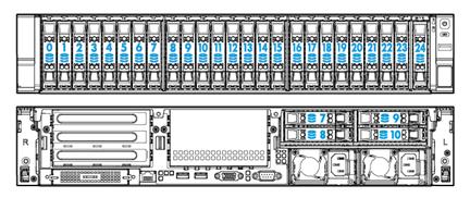
Figure 288 Drive numbering for the 29SFF (25 front+4 rear)+2LFF drive configuration (25SFF server)
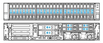
8LFF server
The 8LFF server supports only one drive configuration.
Table 56 presents this drive configuration and its compatible types of storage controllers and NVMe SSD expander modules.
Table 56 Drive, storage controller, and NVMe SSD expander module configurations (8LFF server)
|
Drive backplane and drive expander module |
Drive configuration |
Storage controller |
NVMe SSD expander module |
|
N/A |
8LFF (8 LFF front SAS/SATA drives) |
· Embedded RSTe · Mezzanine · Standard in PCIe slot 2 or 6 |
N/A |
Figure 289 Drive numbering for the 8LFF drive configuration (8LFF server)
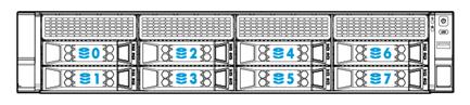
12LFF server
Table 57 presents the drive configurations available for the 12LFF server, their compatible types of storage controllers and NVMe SSD expander modules, and drive numbering schemes.
Table 57 Drive configurations supported by the 12LFF server
|
Drive backplane and drive expander module |
Drive configuration |
Storage controller |
NVMe SSD expander module |
Drive numbering |
|
BP-12LFF-R4900 drive backplane + drive expander module |
12LFF (12 front LFF SAS/SATA drives) |
· Mezzanine · Standard in PCIe slot 2 |
N/A |
See Figure 290. |
|
12LFF+2SFF (12 front LFF SAS/SATA drives + 2 rear SFF SAS/SATA drives) |
· Mezzanine · Standard in PCIe slot 2 The rear drives must be connected to the drive expander module. |
N/A |
See Figure 291. |
|
|
12LFF+4SFF (12 front LFF SAS/SATA drives + 4 rear SFF SAS/SATA or NVMe drives in 4SFF UniBay drive cage) |
· Mezzanine · Standard in PCIe slot 2 |
1 × 4-port NVMe SSD expander module in PCIe slot 5 |
See Figure 292. |
|
|
14LFF (12 front and 2 rear LFF SAS/SATA drives) |
· Mezzanine · Standard in PCIe slot 2 |
N/A |
See Figure 293. |
|
|
16LFF (12 front and 4 rear LFF SAS/SATA drives) |
· Mezzanine · Standard in PCIe slot 8 |
N/A |
See Figure 294. |
|
|
14LFF+2SFF (12 front and 2 rear LFF SAS/SATA drives + 2 rear SFF SAS/SATA drives) |
· Mezzanine · Standard in PCIe slot 2 |
N/A |
See Figure 295. |
|
|
14LFF+4SFF (12 front and 2 rear LFF SAS/SATA drives + 4 rear SFF SAS/SATA drives) |
· Mezzanine · Standard in PCIe slot 2 |
N/A |
See Figure 296. |
|
|
16LFF+2SFF (12 front and 4 rear LFF SAS/SATA drives + 2 rear SFF SAS/SATA drives) |
· Mezzanine · Standard in PCIe slot 8 |
N/A |
See Figure 297. |
|
|
16LFF+4SFF (12 front and 4 rear LFF SAS/SATA drives + 4 rear SFF SAS/SATA drives) |
Mezzanine |
N/A |
See Figure 298. |
|
|
BP-12LFF-NVMe-2U-G3 or BP-12LFF-4UniBay-2U drive backplane |
12LFF (8 front LFF SAS/SATA drives + 4 front LFF NVMe drives) |
Embedded RSTe |
1 × 4-port NVMe SSD expander module in PCIe slot 2 |
See Figure 290. |
|
Mezzanine |
1 × 4-port NVMe SSD expander module in PCIe slot 2 |
|||
|
Standard in PCIe slot 6 |
1 × 4-port NVMe SSD expander module in PCIe slot 5 |
|||
|
12LFF+2SFF (8 front LFF SAS/SATA drives + 4 front LFF NVMe drives + 2 rear SFF SAS/SATA drives) |
Standard in PCIe slot 1 + standard in PCIe slot 2 |
1 × 4-port NVMe SSD expander module in PCIe slot 5 |
See Figure 291. |
|
|
12LFF+2SFF (8 front LFF SAS/SATA drives + 4 front LFF NVMe drives + 2 rear SFF NVMe drives) |
Standard in PCIe slot 1 + standard controller RAID-LSI-9460-8i(2G) or RAID-LSI-9460-8i(4G) in PCIe slot 2 |
1 × 4-port NVMe SSD expander module in PCIe slot 5 |
See Figure 291. |
|
|
12LFF (8 front LFF SAS/SATA drives + 4 front LFF SAS/SATA or NVMe drives in AnyBay slots 8 to 11) |
Standard controller RAID-LSI-9460-16i(4G) in PCIe slot 6 |
1 × 4-port NVMe SSD expander module in PCIe slot 5 |
See Figure 290. |
|
|
Standard in PCIe slot 6 + Mezzanine NOTE: The standard controller is for front drives 8 to 11. The Mezzanine controller is for front drives 0 to 7. |
1 × 4-port NVMe SSD expander module in PCIe slot 5 |
|||
|
Standard controllers in PCIe slots 1 and 2 |
1 × 4-port NVMe SSD expander module in PCIe slot 5 |
|||
|
12LFF+2SFF (8 front LFF SAS/SATA drives + 4 front LFF SAS/SATA or NVMe drives in AnyBay slots 8 to 11 + 2 rear SFF SAS/SATA drives) |
Standard in PCIe slot 6 + Mezzanine NOTE: The standard controller is for front drives 8 to 11 and rear drives. The Mezzanine controller is for front drives 0 to 7. |
1 × 4-port NVMe SSD expander module in PCIe slot 5 |
See Figure 291. |
|
|
Standard controller RAID-LSI-9460-16i(4G) in PCIe slot 6 + standard in PCIe slot 1 |
1 × 4-port NVMe SSD expander module in PCIe slot 5 |
|||
|
12LFF+2SFF (8 front LFF SAS/SATA drives + 4 front LFF SAS/SATA + 2 rear SFF SAS/SATA drives) |
Standard in PCIe slot 6 + Mezzanine NOTE: The standard controller is for front drives 8 to 11 and rear drives. The Mezzanine controller is for front drives 0 to 7. |
N/A |
See Figure 291. |
|
|
Standard controller RAID-LSI-9460-16i(4G) in PCIe slot 6 + standard in PCIe slot 1 |
N/A |
|||
|
BP2-12LFF-2U-G3 12LFF drive backplane |
12LFF (12 front LFF SAS/SATA drives) |
l Mezzanine l Standard in PCIe slot 6 |
N/A |
See Figure 290. |
|
12LFF+2SFF (12 front LFF SAS/SATA drives + 2 rear SFF SAS/SATA drives) |
l Mezzanine l Standard in PCIe slot 6 The rear drives must be connected to the drive backplane. |
N/A |
See Figure 291. |
|
|
12LFF+4SFF (12 front LFF SAS/SATA drives + 4 rear SFF SAS/SATA drives) |
l Mezzanine l Standard in PCIe slot 6 The rear drives must be connected to the drive backplane. |
N/A |
See Figure 292. |
|
|
14LFF (12 front LFF SAS/SATA drives + 2 rear LFF SAS/SATA drives) |
l Mezzanine l Standard in PCIe slot 6 l The rear drives must be connected to the drive backplane. |
N/A |
See Figure 293. |
|
|
16LFF (12 front LFF SAS/SATA drives + 4 rear LFF SAS/SATA drives) |
l Mezzanine l Standard in PCIe slot 6 l The rear drives must be connected to the drive backplane. |
N/A |
See Figure 294. |
|
|
BP-12LFF-G3 drive backplane |
12LFF+2SFF (12 front LFF SAS/SATA drives + 2 rear SFF SAS/SATA drives) |
Standard controllers in PCIe slots 1 and 2 NOTE: The controller in PCIe slot 1 is for front drives 0 to 7. The controller in PCIe slot 2 is for front drives 8 to 11 and rear drives. |
N/A |
See Figure 291. |
|
Mezzanine + standard in PCIe slot 6 NOTE: The Mezzanine controller is for front drives 0 to 7. The standard controller is for front drives 8 to 11 and rear drives. |
N/A |
See Figure 291. |
|
|
NOTE: · The BP2-12LFF-2U-G3 12LFF drive backplane provides functions of a drive expander module and can be used without any drive expander module. · An AnyBay drive slot supports both SAS/SATA drives and NVMe drives. |
Figure 290 Drive numbering for the 12LFF drive configuration (12LFF server)
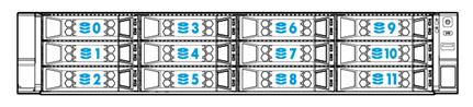
Figure 291 Drive numbering for the 12LFF+2SFF drive configuration (12LFF server)
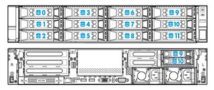
Figure 292 Drive numbering for the 12LFF+4SFF drive configuration (12LFF server)
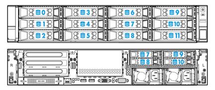
Figure 293 Drive numbering for the 14LFF (12 front+2 rear) drive configuration (12LFF server)
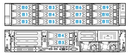
Figure 294 Drive numbering for the 16LFF (12 front+4 rear) drive configuration (12LFF server)
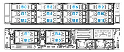
Figure 295 Drive numbering for the 14LFF (12 front+2 rear)+2SFF drive configuration (12LFF server)
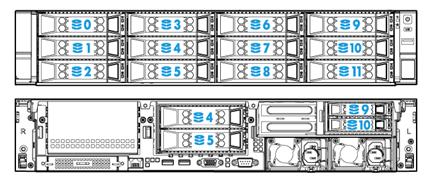
Figure 296 Drive numbering for the 14LFF (12 front+2 rear)+4SFF drive configuration (12LFF server)
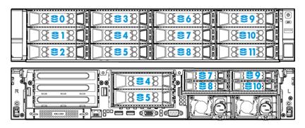
Figure 297 Drive numbering for the 16LFF (12 front+4 rear)+2SFF drive configuration (12LFF server)
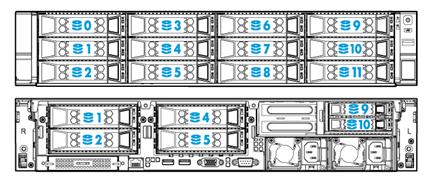
Figure 298 Drive numbering for the 16LFF (12 front+4 rear)+4SFF drive configuration (12LFF server)
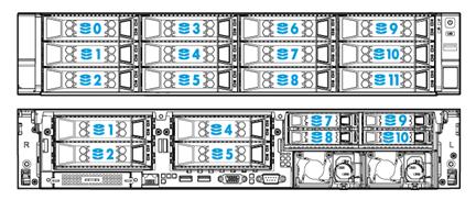
PCIe modules
Typically, the PCIe modules are available in the following standard form factors:
· LP—Low profile.
· FHHL—Full height and half length.
· FHFL—Full height and full length.
· HHHL—Half height and half length.
· HHFL—Half height and full length.
Some PCIe modules, such as mezzanine storage controllers, are in non-standard form factors.
Storage controllers
The server supports the following types of storage controllers depending on their form factors:
· Embedded RAID controller—Embedded in the server and does not require installation.
· Mezzanine storage controller—Installed on the Mezzanine storage controller connector of the system board and does not require a riser card for installation.
· Standard storage controller—Comes in a standard PCIe form factor and typically requires a riser card for installation.
For some storage controllers, you can order a power fail safeguard module to prevent data loss from power outages. This module provides a flash card and a supercapacitor. When a system power failure occurs, the supercapacitor provides power for a minimum of 20 seconds. During this interval, the storage controller can transfer data from DDR memory to the flash card, where the data remains indefinitely or until the controller retrieves the data. If the storage controller contains a built-in flash card, you can order only a supercapacitor.
Embedded RSTe RAID controller
|
Item |
Specifications |
|
Type |
Embedded in PCH of the system board |
|
Connectors |
· One onboard ×8 mini-SAS connector · One onboard ×1 SATA connector |
|
Number of internal ports |
9 internal SATA ports |
|
Drive interface |
6 Gbps SATA 3.0 |
|
PCIe interface |
PCIe2.0 ×4 |
|
RAID levels |
0, 1, 5, 10 |
|
Built-in cache memory |
N/A |
|
Supported drives |
· SATA HDD · SATA SSD |
|
Power fail safeguard module |
Not supported |
|
Firmware upgrade |
Upgraded with the BIOS |
RAID-P460-M2
|
Item |
Specifications |
|
Type |
Mezzanine storage controller |
|
Form factor |
137 × 103 mm (5.39 × 4.06 in) |
|
Connectors |
One ×8 mini-SAS-HD connector |
|
Number of internal ports |
8 internal SAS ports (compatible with SATA) |
|
Drive interface |
12 Gbps SAS 3.0 or 6 Gbps SATA 3.0 |
|
PCIe interface |
PCIe3.0 ×8 |
|
RAID levels |
0, 1, 5, 6,10, 50, 60 |
|
Built-in cache memory |
2 GB internal cache module (DDR4-2133 MHz) |
|
Supported drives |
· SAS HDD · SAS SSD · SATA HDD · SATA SSD |
|
Power fail safeguard module |
BAT-PMC-G3 The supercapacitor is optional. |
|
Built-in flash card |
Available |
|
Supercapacitor connector |
Available |
|
Firmware upgrade |
Online upgrade |
RAID-P460-M4
|
Item |
Specifications |
|
Type |
Mezzanine storage controller |
|
Form factor |
137 × 103 mm (5.39 × 4.06 in) |
|
Connectors |
One ×8 mini-SAS connector |
|
Number of internal ports |
8 internal SAS ports (compatible with SATA) |
|
Drive interface |
12 Gbps SAS 3.0 or 6 Gbps SATA 3.0 |
|
PCIe interface |
PCIe3.0 ×8 |
|
RAID levels |
0, 1, 5, 6,10, 50, 60 |
|
Built-in cache memory |
4 GB internal cache module (DDR4-2133 MHz, 72-bit bus at 12.8 Gbps) |
|
Supported drives |
· SAS HDD · SAS SSD · SATA HDD · SATA SSD |
|
Power fail safeguard module |
BAT-PMC-G3 The supercapacitor is optional. |
|
Built-in flash card |
Available |
|
Supercapacitor connector |
Available |
|
Firmware upgrade |
Online upgrade |
HBA-LSI-9300-8i-A1-X
|
Item |
Specifications |
|
Type |
Standard storage controller |
|
Form factor |
LP |
|
Connectors |
One ×8 mini-SAS-HD connector |
|
Number of internal ports |
8 internal SAS ports (compatible with SATA) |
|
Drive interface |
12 Gbps SAS 3.0 or 6 Gbps SATA 3.0 |
|
PCIe interface |
PCIe3.0 ×8 |
|
RAID levels |
N/A |
|
Built-in cache memory |
N/A |
|
Supported drives |
· SAS HDD · SAS SSD · SATA HDD · SATA SSD |
|
Power fail safeguard module |
Not supported |
|
Built-in flash card |
N/A |
|
Firmware upgrade |
Online upgrade |
HBA-LSI-9311-8i
|
Item |
Specifications |
|
Type |
Standard storage controller |
|
Form factor |
LP |
|
Connectors |
One ×8 mini-SAS-HD connector |
|
Number of internal ports |
8 internal SAS ports (compatible with SATA) |
|
Drive interface |
12 Gbps SAS 3.0 or 6 Gbps SATA 3.0 |
|
PCIe interface |
PCIe3.0 ×8 |
|
RAID levels |
0, 1, 1E, 10 |
|
Built-in cache memory |
N/A |
|
Supported drives |
· SAS HDD · SAS SSD · SATA HDD · SATA SSD |
|
Power fail safeguard module |
Not supported |
|
Built-in flash card |
N/A |
|
Firmware upgrade |
Online upgrade |
HBA-LSI-9440-8i
|
Item |
Specifications |
|
Type |
Standard storage controller |
|
Form factor |
LP |
|
Connectors |
One ×8 mini-SAS-HD connector |
|
Number of internal ports |
8 internal SAS ports (compatible with SATA) |
|
Drive interface |
12 Gbps SAS 3.0 or 6 Gbps SATA 3.0 |
|
PCIe interface |
PCIe3.1 ×8 |
|
RAID levels |
0, 1, 5, 10, 50 |
|
Built-in cache memory |
N/A |
|
Supported drives |
· SAS HDD · SAS SSD · SATA HDD · SATA SSD |
|
Power fail safeguard module |
Not supported |
|
Built-in flash card |
N/A |
|
Firmware upgrade |
Online upgrade |
RAID-P460-B2
|
Item |
Specifications |
|
Type |
Standard storage controller |
|
Form factor |
LP |
|
Connectors |
One ×8 mini-SAS-HD connector |
|
Number of internal ports |
8 internal SAS ports (compatible with SATA) |
|
Drive interface |
12 Gbps SAS 3.0 or 6 Gbps SATA 3.0 |
|
PCIe interface |
PCIe3.0 ×8 |
|
RAID levels |
0, 1, 5, 6, 10, 50, 60 |
|
Built-in cache memory |
2 GB internal cache module (DDR4-2133 MHz) |
|
Supported drives |
· SAS HDD · SAS SSD · SATA HDD · SATA SSD |
|
Power fail safeguard module |
BAT-PMC-G3 The supercapacitor is optional. |
|
Built-in flash card |
Available |
|
Supercapacitor connector |
Available |
|
Firmware upgrade |
Online upgrade |
RAID-P460-B4
|
Item |
Specifications |
|
Type |
Standard storage controller |
|
Form factor |
LP |
|
Connectors |
One ×8 mini-SAS connector |
|
Number of internal ports |
8 internal SAS ports (compatible with SATA) |
|
Drive interface |
12 Gbps SAS 3.0 or 6 Gbps SATA 3.0 |
|
PCIe interface |
PCIe3.0 ×8 |
|
RAID levels |
0, 1, 5, 6, 10, 50, 60 |
|
Built-in cache memory |
4 GB internal cache module (DDR4-2133 MHz) |
|
Supported drives |
· SAS HDD · SAS SSD · SATA HDD · SATA SSD |
|
Power fail safeguard module |
BAT-PMC-G3 The supercapacitor is optional. |
|
Built-in flash card |
Available |
|
Supercapacitor connector |
Available |
|
Firmware upgrade |
Online upgrade |
RAID-LSI-9361-8i(1G)-A1-X
|
Item |
Specifications |
|
Type |
Standard storage controller |
|
Form factor |
LP |
|
Connectors |
One ×8 mini-SAS-HD connector |
|
Number of internal ports |
8 internal SAS ports (compatible with SATA) |
|
Drive interface |
12 Gbps SAS 3.0 or 6 Gbps SATA 3.0 |
|
PCIe interface |
PCIe3.0 ×8 |
|
RAID levels |
0, 1, 5, 6, 10, 50, 60 |
|
Built-in cache memory |
1 GB internal cache module (DDR3-1866 MHz) |
|
Supported drives |
· SAS HDD · SAS SSD · SATA HDD · SATA SSD |
|
Power fail safeguard module |
Flash-LSI-G2, optional. |
|
Built-in flash card |
N/A |
|
Supercapacitor connector |
N/A The supercapacitor connector is on the flash card of the power fail safeguard module. |
|
Firmware upgrade |
Online upgrade |
RAID-LSI-9361-8i(2G)-1-X
|
Item |
Specifications |
|
Type |
Standard storage controller |
|
Form factor |
LP |
|
Connectors |
One ×8 mini-SAS-HD connector |
|
Number of internal ports |
8 internal SAS ports (compatible with SATA) |
|
Drive interface |
12 Gbps SAS 3.0 or 6 Gbps SATA 3.0 |
|
PCIe interface |
PCIe3.0 ×8 |
|
RAID levels |
0, 1, 5, 6, 10, 50, 60 |
|
Built-in cache memory |
2 GB internal cache module (DDR3-1866 MHz) |
|
Supported drives |
· SAS HDD · SAS SSD · SATA HDD · SATA SSD |
|
Power fail safeguard module |
Flash-LSI-G2, optional. |
|
Built-in flash card |
N/A |
|
Supercapacitor connector |
N/A The supercapacitor connector is on the flash card of the power fail safeguard module. |
|
Firmware upgrade |
Online upgrade |
RAID-LSI-9460-8i(2G)
|
Item |
Specifications |
|
Type |
Standard storage controller |
|
Form factor |
LP |
|
Connectors |
One ×8 mini-SAS-HD connector |
|
Number of internal ports |
8 internal SAS ports (compatible with SATA) |
|
Drive interface |
12 Gbps SAS 3.0 or 6 Gbps SATA 3.0 |
|
PCIe interface |
PCIe3.1 ×8 |
|
RAID levels |
· HDDs and SSDs: 0, 1, 5, 6, 10, 50, 60 · NVMe drives: 0, 1 |
|
Built-in cache memory |
2 GB internal cache module (DDR4-2133 MHz) |
|
Supported drives |
· SAS HDD · SAS SSD · SATA HDD · SATA SSD · NVMe |
|
Power fail safeguard module |
BAT-LSI-G3 The supercapacitor is optional. |
|
Built-in flash card |
Available |
|
Supercapacitor connector |
Available |
|
Firmware upgrade |
Online upgrade |
RAID-LSI-9460-8i(4G)
|
Item |
Specifications |
|
Type |
Standard storage controller |
|
Form factor |
LP |
|
Connectors |
One ×8 mini-SAS-HD connector |
|
Number of internal ports |
8 internal SAS ports (compatible with SATA) |
|
Drive interface |
12 Gbps SAS 3.0 or 6 Gbps SATA 3.0 |
|
PCIe interface |
PCIe3.1 ×8 |
|
RAID levels |
· HDDs and SSDs: 0, 1, 5, 6, 10, 50, 60 · NVMe drives: 0, 1 |
|
Built-in cache memory |
4 GB internal cache module (DDR4-2133 MHz) |
|
Supported drives |
· SAS HDD · SAS SSD · SATA HDD · SATA SSD · NVMe |
|
Power fail safeguard module |
BAT-LSI-G3 The supercapacitor is optional. |
|
Built-in flash card |
Available |
|
Supercapacitor connector |
Available |
|
Firmware upgrade |
Online upgrade |
RAID-LSI-9460-16i(4G)
|
Item |
Specifications |
|
Type |
Standard storage controller |
|
Form factor |
LP |
|
Connectors |
Four ×4 mini-SAS-HD connector |
|
Number of internal ports |
16 internal SAS ports (compatible with SATA) |
|
Drive interface |
12 Gbps SAS 3.0 or 6 Gbps SATA 3.0 |
|
PCIe interface |
PCIe3.1 ×8 |
|
RAID levels |
0, 1, 5, 6, 10, 50, 60 |
|
Built-in cache memory |
4 GB internal cache module (DDR4-2133 MHz) |
|
Supported drives |
· SAS HDD · SAS SSD · SATA HDD · SATA SSD |
|
Power fail safeguard module |
BAT-LSI-G3 The supercapacitor is optional. |
|
Built-in flash card |
Available |
|
Supercapacitor connector |
Available |
|
Firmware upgrade |
Online upgrade |
Power fail safeguard module and supercapacitor
|
Model |
Specifications |
|
Flash-LSI-G2 |
LSI G2 power fail safeguard module (with supercapacitor module) (2U LSI RAID) |
|
BAT-LSI-G3 |
LSI G3 supercapacitor module (for 2U server) |
|
BAT-PMC-G3 |
PMC G3 supercapacitor module (applicable to 2U embedded RAID controller) |
|
BAT-PMC-G3 |
PMC G3 supercapacitor module (applicable to 2U LSI RAID controller) |
|
SCAP-LSI-G3-2U |
LSI G3 flash power fail safeguard module (applicable to 1SFF) |
|
SCAP-LSI-G2-2U |
LSI G2 flash power fail safeguard module (applicable to 1SFF) |
NVMe SSD expander modules
|
Model |
Specifications |
|
EX-4NVMe-A |
4-port NVMe SSD expander module, which supports a maximum of 4 NVMe SSD drives. |
|
EX-8NVMe-A |
8-port NVMe SSD expander module, which supports a maximum of 8 NVMe SSD drives. |
GPU modules
GPU-V100
|
Item |
Specifications |
|
PCIe interface |
PCIe3.0 ×16 |
|
Form factor |
FH3/4FL, dual-slot wide |
|
Maximum power consumption |
250 W |
|
Memory size |
16 GB HBM2 |
|
Memory bus width |
4096 bits |
|
Memory bandwidth |
900 Gbps |
|
Power connector |
Available |
|
Required chassis air baffle |
GPU-dedicated chassis air baffle |
GPU-V100-32G
|
Item |
Specifications |
|
PCIe interface |
PCIe3.0 ×16 |
|
Form factor |
FH3/4FL, dual-slot wide |
|
Maximum power consumption |
250 W |
|
Memory size |
32 GB HBM2 |
|
Memory bus width |
4096 bits |
|
Memory bandwidth |
900 Gbps |
|
Power connector |
Available |
|
Required chassis air baffle |
GPU-dedicated chassis air baffle |
GPU-T4
|
Item |
Specifications |
|
PCIe interface |
PCIe3.0 ×16 |
|
Form factor |
LP, single-slot wide |
|
Maximum power consumption |
70 W |
|
Memory size |
16 GB GDDR6 |
|
Memory bus width |
256 bits |
|
Memory bandwidth |
320 Gbps |
|
Power connector |
N/A |
|
Required chassis air baffle |
Standard chassis air baffle |
GPU-P40-X
|
Item |
Specifications |
|
PCIe interface |
PCIe3.0 ×16 |
|
Form factor |
FH3/4FL, dual-slot wide |
|
Maximum power consumption |
250 W |
|
Memory size |
24 GB GDDR5 |
|
Memory bus width |
384 bits |
|
Memory bandwidth |
346 Gbps |
|
Power connector |
Available |
|
Required chassis air baffle |
Standard chassis air baffle |
GPU-M10-X
|
Item |
Specifications |
|
PCIe interface |
PCIe3.0 ×16 |
|
Form factor |
FH3/4FL, dual-slot wide |
|
Maximum power consumption |
250 W |
|
Memory size |
32 GB GDDR5 |
|
Memory bus width |
128 bits ×4 |
|
Memory bandwidth |
332 Gbps |
|
Power connector |
Available |
|
Required chassis air baffle |
Standard chassis air baffle |
GPU module and riser card compatibility
|
Riser card |
PCIe riser connector |
PCIe slot |
Available GPU modules |
|
RC-GPU/FHHL-2U-G3-1 |
Connector 1 or 2 |
Slot 2 or 5 |
· GPU-M4-1 · GPU-M4000-1-X · GPU-K80-1 · GPU-M60-1-X · GPU-P4-X · GPU-T4 · GPU-M2000 · GPU-P40-X · GPU-M10-X · GPU-MLU100-D3 |
|
Slot 3 or 6 |
Not supported |
||
|
RC-GPU/FHHL-2U-G3-2 |
Connector 3 |
Slot 7 |
· GPU-M4-1 · GPU-M4000-1-X · GPU-K80-1 · GPU-M60-1-X · GPU-P4-X · GPU-M2000 · GPU-P40-X · GPU-M10-X |
|
Slot 8 |
Not supported |
||
|
RC-2*FHFL-2U-G3 |
Connector 1 |
Slot 1 |
· GPU-M4-1 · GPU-M4000-1-X · GPU-P4-X · GPU-T4 · GPU-M2000 · GPU-MLU100-D3 |
|
Slot 2 |
· GPU-M4-1 · GPU-M4000-1-X · GPU-P4-X · GPU-T4 · GPU-M2000 · GPU-MLU100-D3 |
||
|
RC-FHHL-2U-G3-1 |
Connector 1 or 2 |
Slot 2 or 5 |
· GPU-P100 · GPU-V100-32G · GPU-V100 |
|
Slot 3 or 6 |
Not supported |
||
|
RC-3GPU-R4900-G3 |
Connector 1 or 2 |
Slot 1 or 4 |
· GPU-P4-X · GPU-T4 · GPU-MLU100-D3 |
|
Slot 2 or 5 |
|||
|
Slot 3 or 6 |
|||
|
RC-FHHL-2U-G3-2 |
Connector 3 |
Slot 7 |
· GPU-P100 · GPU-V100-32G · GPU-V100 |
|
Slot 8 |
Not supported |
||
|
RC-2GPU-R4900-G3 |
Connector 3 |
Slot 7 |
· GPU-P4-X · GPU-T4 · GPU-MLU100-D3 |
|
Slot 8 |
PCIe Ethernet adapters
In addition to the PCIe Ethernet adapters, the server also supports mLOM Ethernet adapters (see "mLOM Ethernet adapters").
Table 58 PCIe Ethernet adapters
|
Model |
Ports |
Connector |
Data rate |
Bus type |
Form factor |
NCSI |
|
CNA-10GE-2P-560F-B2-1-X |
2 |
SFP+ |
10 Gbps |
PCIe2.0 ×8 |
LP |
Not supported |
|
CNA-560T-B2-10Gb-2P-1-X |
2 |
RJ-45 |
10 Gbps |
PCIe3.0 ×8 |
LP |
Not supported |
|
CNA-QL41262HLCU-11-2*25G |
2 |
SFP28 |
25 Gbps |
PCIe3.0 ×8 |
LP |
Not supported |
|
IB-MCX555A-ECAT-100Gb-1P |
1 |
QSFP28 |
100 Gbps |
PCIe3.0 ×16 |
LP |
Not supported |
|
IB-MCX555A-ECAT-100Gb-1P-1 |
1 |
QSFP28 |
100 Gbps |
PCIe3.0 ×16 |
LP |
Not supported |
|
IB-MCX453A-FCAT-56/40Gb-1P |
1 |
QSFP28 |
56 Gbps |
PCIe3.0 ×8 |
LP |
Not supported |
|
IB-MCX453A-FCAT-56/40Gb-1P-1 |
1 |
QSFP28 |
56 Gbps |
PCIe3.0 ×8 |
LP |
Not supported |
|
IB-MCX354A-FCBT-56/40Gb-2P-X |
2 |
QSFP+ |
40/56 Gbps |
PCIe3.0 ×8 |
LP |
Not supported |
|
NIC-10GE-2P-520F-B2-1-X |
2 |
SFP+ |
10 Gbps |
PCIe3.0 ×8 |
LP |
Not supported |
|
NIC-10GE-2P-530F-B2-1-X |
2 |
SFP+ |
10 Gbps |
PCIe2.0 ×8 |
LP |
Not supported |
|
NIC-620F-B2-25Gb-2P-1-X |
2 |
SFP28 |
25 Gbps |
PCIe3.0 ×8 |
LP |
Supported |
|
NIC-GE-4P-360T-B2-1-X |
4 |
RJ-45 |
10/100/1000 Mbps |
PCIe2.0 ×4 |
LP |
Not supported |
|
NIC-BCM957416-T-B-10Gb-2P |
2 |
RJ-45 |
10 Gbps |
PCIe3.0 ×8 |
LP |
Not supported |
|
NIC-BCM957302-F-B-10Gb-2P |
2 |
SFP+ |
10 Gbps |
PCIe3.0 ×8 |
LP |
Not supported |
|
NIC-BCM957412-F-B-10Gb-2P |
2 |
SFP+ |
10 Gbps |
PCIe3.0 ×8 |
LP |
Not supported |
|
NIC-BCM957414-F-B-25Gb-2P |
2 |
SFP28 |
25 Gbps |
PCIe3.0 ×8 |
LP |
Not supported |
|
NIC-957454A4540C-B-100G-1P |
1 |
QSFP28 |
100 Gbps |
PCIe 3.0 ×16 |
LP |
Not supported |
|
NIC-CAVIUM-F-B-25Gb-2P |
2 |
SFP28 |
25 Gbps |
PCIe3.0 ×8 |
LP |
Not supported |
|
NIC-MCX415A-F-B-100Gb-1P |
1 |
QSFP28 |
100 Gbps |
PCIe3.0 ×16 |
LP |
Not supported |
|
NIC-MCX416A-F-B-40/56-2P |
2 |
QSFP28 |
56 Gbps |
PCIe 3.0 ×16 |
LP |
Not supported |
|
NIC-MCX416A-F-B-100Gb-2P |
2 |
SFP28 |
25 Gbps |
PCIe3.0 ×8 |
LP |
Not supported |
|
NIC-MCX4121A-F-B-10Gb-2P |
2 |
SFP28 |
10 Gbps |
PCIe3.0 ×8 |
LP |
Not supported |
|
NIC-X520DA2-F-B-10Gb-2P |
2 |
SFP+ |
10 Gbps |
PCIe2.0 ×8 |
LP |
Not supported |
|
NIC-X540-T2-T-10Gb-2P |
2 |
RJ-45 |
10 Gbps |
PCIe2.0 ×8 |
LP |
Not supported |
|
NIC-XL710-QDA1-F-40Gb-1P |
1 |
QSFP+ |
40 Gbps |
PCIe3.0 ×8 |
LP |
Not supported |
|
NIC-XL710-QDA2-F-40Gb-2P |
2 |
QSFP+ |
40 Gbps |
PCIe3.0 ×8 |
LP |
Not supported |
|
NIC-X710DA2-F-B-10Gb-2P-2 |
2 |
SFP+ |
10 Gbps |
PCIe3.0 ×8 |
LP |
Not supported |
|
NIC-X710DA4-F-B-10Gb-4P |
4 |
SFP+ |
10 Gbps |
PCIe3.0 ×8 |
LP |
Not supported |
|
NIC-MCX4121A-F-B-25Gb-2P |
2 |
SFP28 |
25 Gbps |
PCIe3.0 ×8 |
LP |
Not supported |
|
NIC-MCX512A-ACAT-F-2*25Gb |
2 |
SFP28 |
25 Gbps |
PCIe3.0 ×8 |
LP |
Not supported |
|
NIC-XXV710-F-B-25Gb-2P |
2 |
SFP28 |
25 Gbps |
PCIe3.0 ×8 |
LP |
Not supported |
|
NIC-OPA-100Gb-1P |
1 |
QSFP28 |
100 Gbps |
PCIe3.0 ×16 |
LP |
Not supported |
|
NIC-iETH-PS225-H16 |
2 |
SFP28 |
25 Gbps |
PCIe3.0 ×8 |
LP |
Supported |
|
NIC-iETH-PS225-H08 |
2 |
SFP28 |
25 Gbps |
PCIe3.0 ×8 |
LP |
Supported |
|
NIC-iETH-MBF1M332A-AENAT-2P |
2 |
SFP28 |
25 Gbps |
PCIe3.0/PCIe4.0 ×8 |
LP |
Supported |
FC HBAs
FC-HBA-QLE2560-8Gb-1P-1-X
|
Item |
Specifications |
|
Form factor |
LP |
|
Ports |
1 |
|
Connector |
SFP+ |
|
Data rate |
8 Gbps |
FFC-HBA-QLE2562-8Gb-2P-1-X
|
Item |
Specifications |
|
Form factor |
LP |
|
Ports |
2 |
|
Connector |
SFP+ |
|
Data rate |
8 Gbps |
FC-HBA-QLE2690-16Gb-1P-1-X
|
Item |
Specifications |
|
Form factor |
LP |
|
Ports |
1 |
|
Connector |
SFP+ |
|
Data rate |
16 Gbps |
FC-HBA-QLE2692-16Gb-2P-1-X
|
Item |
Specifications |
|
Form factor |
LP |
|
Ports |
2 |
|
Connector |
SFP+ |
|
Data rate |
16 Gbps |
HBA-8Gb-LPe12000-1P-1-X
|
Item |
Specifications |
|
Form factor |
LP |
|
Ports |
1 |
|
Connector |
SFP+ |
|
Data rate |
8 Gbps |
HBA-8Gb-LPe12002-2P-1-X
|
Item |
Specifications |
|
Form factor |
LP |
|
Ports |
2 |
|
Connector |
SFP+ |
|
Data rate |
8 Gbps |
HBA-16Gb-LPe31000-1P-1-X
|
Item |
Specifications |
|
Form factor |
LP |
|
Ports |
1 |
|
Connector |
SFP+ |
|
Data rate |
16 Gbps |
HBA-16Gb-LPe31002-2P-1-X
|
Item |
Specifications |
|
Form factor |
LP |
|
Ports |
2 |
|
Connector |
SFP+ |
|
Data rate |
16 Gbps |
FC-HBA-LPe32000-32Gb-1P-X
|
Item |
Specifications |
|
Form factor |
LP |
|
Ports |
1 |
|
Connector |
SFP+ |
|
Data rate |
32 Gbps |
FC-HBA-LPe32002-32Gb-2P-X
|
Item |
Specifications |
|
Form factor |
LP |
|
Ports |
2 |
|
Connector |
SFP+ |
|
Data rate |
32 Gbps |
FC-HBA-QLE2740-32Gb-1P
|
Item |
Specifications |
|
Form factor |
LP |
|
Ports |
1 |
|
Connector |
SFP+ |
|
Data rate |
32 Gbps |
FC-HBA-QLE2742-32Gb-2P
|
Item |
Specifications |
|
Form factor |
LP |
|
Ports |
2 |
|
Connector |
SFP+ |
|
Data rate |
32 Gbps |
mLOM Ethernet adapters
In addition to mLOM Ethernet adapters, the server also supports PCIe Ethernet adapters (see "PCIe Ethernet adapters").
By default, port 1 on an mLOM Ethernet adapter acts as an HDM shared network port.
NIC-GE-4P-360T-L3
|
Item |
Specifications |
|
Dimensions |
128 × 68 mm (5.04 × 2.68 in) |
|
Ports |
4 |
|
Connector |
RJ-45 |
|
Data rate |
1000 Mbps |
|
Bus type |
1000BASE-X ×4 |
|
NCSI |
Supported |
NIC-10GE-2P-560T-L2
|
Item |
Specifications |
|
Dimensions |
128 × 68 mm (5.04 × 2.68 in) |
|
Ports |
2 |
|
Connector |
RJ-45 |
|
Data rate |
1/10 Gbps |
|
Bus type |
10G-KR ×2 |
|
NCSI |
Supported |
NIC-10GE-2P-560F-L2
|
Item |
Specifications |
|
Dimensions |
128 × 68 mm (5.04 × 2.68 in) |
|
Ports |
2 |
|
Connector |
SFP+ |
|
Data rate |
10 Gbps |
|
Bus type |
10G-KR ×2 |
|
NCSI |
Supported |
Riser cards
Riser card guidelines
Each PCIe slot in a riser card can supply a maximum of 75 W power to the PCIe module. You must connect a separate power cord to the PCIe module only if it requires more than 75 W power.
PCIe slot numbering
The server provides a maximum of eight PCIe slots, as shown in Figure 299.
Figure 299 PCIe slots at the rear panel
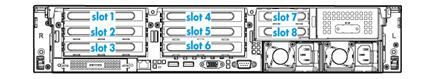
Riser cards for riser connector 1 or 2
If a riser card can be installed on riser connector 1 or 2, the slot numbers of its PCIe slots are presented in the m/n format in this document.
· The m argument represents the PCIe slot number on connector 1.
· The n argument represents the PCIe slot number on connector 2.
For example, PCIe slot 2/5 represents that a PCIe slot is numbered 2 or 5 when the riser card is installed on riser connector 1 or riser connector 2, respectively.
RC-2*FHFL-2U-G3
The riser card must be used together with a RC-Mezz-Riser-G3 PCIe riser card.
|
Item |
Specifications |
|
PCIe riser connector |
Connector 1 |
|
PCIe slots |
· Slot 1, PCIe3.0 ×16 (16, 8, 4, 2, 1) · Slot 2, PCIe3.0 ×16 (16, 8, 4, 2, 1) NOTE: The numbers in parentheses represent link widths. Both slots support single-slot wide GPU modules. |
|
Form factors of PCIe modules |
FHFL |
|
Maximum power supplied per PCIe slot |
75 W |
Figure 300 PCIe slots on the RC-2*FHFL-2U-G3 riser card
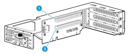
|
(1) PCIe slot 1 |
(2) PCIe slot 2 |
RC-3GPU-R4900-G3
|
Item |
Specifications |
|
PCIe riser connector |
· Connector 1 · Connector 2 |
|
PCIe slots |
· Slot 1/4, PCIe3.0 ×16 (8, 4, 2, 1) · Slot 2/5, PCIe3.0 ×16 (8, 4, 2, 1) · Slot 3/6, PCIe3.0 ×8 (8, 4, 2, 1) NOTE: The numbers in parentheses represent link widths. |
|
Available PCIe modules |
GPU-P4-X, GPU-T4, and GPU-MLU100-D3 GPU modules |
|
Maximum power supplied per PCIe slot |
75 W |
Figure 301 PCIe slots on the RC-3GPU-R4900-G3 riser card

|
(1) PCIe slot 1/4 |
(2) PCIe slot 2/5 |
(3) PCIe slot 3/6 |
RC-FHHL-2U-G3-1
|
Item |
Specifications |
|
PCIe riser connector |
· Connector 1 · Connector 2 |
|
PCIe slots |
· Slot 2/5: PCIe3.0 ×16 (16, 8, 4, 2, 1) · Slot 3/6: PCIe3.0 ×8 (8, 4, 2, 1) NOTE: The numbers in parentheses represent link widths. |
|
Form factors of PCIe modules |
FHHL |
|
Maximum power supplied per PCIe slot |
75 W |
Figure 302 PCIe slots on the RC-FHHL-2U-G3-1 riser card
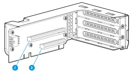
|
(1) PCIe slot 2/5 |
(2) PCIe slot 3/6 |
RC-GPU/FHHL-2U-G3-1
|
Item |
Specifications |
|
PCIe riser connector |
· Connector 1 · Connector 2 |
|
PCIe slots |
· Slot 2/5, PCIe3.0 ×16 (16, 8, 4, 2, 1) · Slot 3/6, PCIe3.0 ×8 (8, 4, 2, 1) NOTE: The numbers in parentheses represent link widths. |
|
Form factors of PCIe modules |
FHHL (only slot 2/5 supports single-wide and double-wide GPU modules) |
|
Maximum power supplied per PCIe slot |
75 W |
Figure 303 PCIe slots on the RC-GPU/FHHL-2U-G3-1 riser card
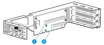
|
(1) PCIe slot 2/5 |
(2) PCIe slot 3/6 |
RS-3*FHHL-R4900
|
Item |
Specifications |
|
PCIe riser connector |
· Connector 1 · Connector 2 |
|
PCIe slots |
· Slot 1/4, PCIe3.0 ×16 (8, 4, 2, 1) · Slot 2/5, PCIe3.0 ×16 (8, 4, 2, 1) · Slot 3/6, PCIe3.0 ×8 (8, 4, 2, 1) NOTE: The numbers in parentheses represent link widths. |
|
Form factors of PCIe modules |
FHHL |
|
Maximum power supplied per PCIe slot |
75 W |
Figure 304 PCIe slots on the RS-3*FHHL-R4900 riser card
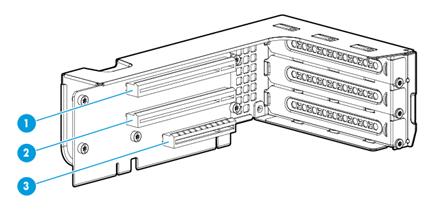
|
(1) PCIe slot 1/4 |
(2) PCIe slot 2/5 |
(3) PCIe slot 3/6 |
Riser cards for riser connector 3
RC-2*LP-2U-G3
|
Item |
Specifications |
|
PCIe riser connector |
Connector 3 |
|
PCIe slots |
· Slot 7, PCIe3.0 ×16 (16, 8, 4, 2, 1) · Slot 8, PCIe3.0 ×8 (8, 4, 2, 1) NOTE: The numbers in parentheses represent link widths. |
|
Form factors of PCIe modules |
LP |
|
Maximum power supplied per PCIe slot |
75 W |
Figure 305 PCIe slots on the RC-2*LP-2U-G3 riser card
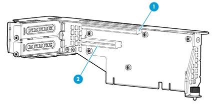
|
(1) PCIe slot 7 |
(2) PCIe slot 8 |
RC-2GPU-R4900-G3
|
Item |
Specifications |
|
PCIe riser connector |
Connector 3 |
|
PCIe slots |
· Slot 7: PCIe3.0 ×16 (16, 8, 4, 2, 1) · Slot 8: PCIe3.0 ×8 (8, 4, 2, 1) NOTE: The numbers in parentheses represent link widths. |
|
Available PCIe modules |
GPU-P4-X, GPU-T4, and GPU-MLU100-D3 GPU modules |
|
Maximum power supplied per PCIe slot |
75 W |
Figure 306 PCIe slots on the RC-2GPU-R4900-G3 riser card
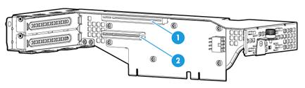
|
(1) PCIe slot 7 |
(2) PCIe slot 8 |
RC-FHHL-2U-G3-2
|
Item |
Specifications |
|
PCIe riser connector |
Connector 3 |
|
PCIe slots |
· Slot 7, PCIe3.0 ×16 (16, 8, 4, 2, 1) · Slot 8, PCIe3.0 ×8 (8, 4, 2, 1) NOTE: The numbers in parentheses represent link widths. |
|
Form factors of PCIe modules |
FHHL |
|
Maximum power supplied per PCIe slot |
75 W |
Figure 307 PCIe slots on the RC-FHHL-2U-G3-2 riser card
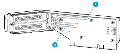
|
(1) PCIe slot 7 |
(2) PCIe slot 8 |
RC-GPU/FHHL-2U-G3-2
|
Item |
Specifications |
|
PCIe riser connector |
Connector 3 |
|
PCIe slots |
· Slot 7: PCIe3.0 ×16 (16, 8, 4, 2, 1) · Slot 8: PCIe3.0 ×8 (8, 4, 2, 1) NOTE: The numbers in parentheses represent link widths. |
|
Form factors of PCIe modules |
· Slot 7: FHFL (including single-wide and double-wide GPU modules) · Slot 8: FHHL |
|
Maximum power supplied per PCIe slot |
75 W |
Figure 308 PCIe slots on the RC-GPU/FHHL-2U-G3-2 riser card
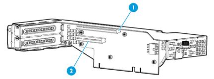
|
(1) PCIe slot 7 |
(2) PCIe slot 8 |
Riser cards for Mezzanine storage controller connector
RC-Mezz-Riser-G3
The RC-Mezz-Riser-G3 Mezz PCIe riser card is used together with the RC-2*FHFL-2U-G3 riser card.
|
Item |
Specifications |
|
Installation location |
Mezzanine storage controller connector |
|
PCIe slots |
One slot, PCIe ×8 |
Fans
Fan layout
The server supports a maximum of six hot swappable fans. Figure 309 shows the layout of the fans in the chassis.
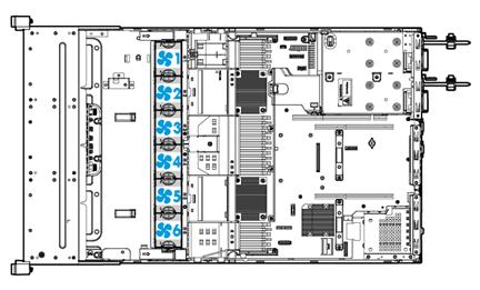
Fan specifications
|
Item |
Specifications |
|
Model |
FAN-2U-G3 |
|
Form factor |
2U standard fan |
Power supplies
The power supplies have an overtemperature protection mechanism. A power supply stops working when an overtemperature occurs and automatically recovers when the overtemperature condition is removed.
550 W Platinum power supply
|
Item |
Specifications |
|
Model |
· PSR550-12A · PSR550-12A-1 · PSR550-12A-2 |
|
Rated input voltage range |
· 100 VAC to 240 VAC @ 50/60 Hz (10 A receptacle) · 192 VDC to 288 VDC (240 HVDC power source) |
|
Maximum rated input current |
· 8.0 A @ 100 VAC to 240 VAC · 2.75 A @ 240 VDC |
|
Maximum rated output power |
550 W |
|
Efficiency at 50 % load |
94%, 80 Plus Platinum level |
|
Temperature requirements |
· Operating temperature: 0°C to 50°C (32°F to 122°F) · Storage temperature: –40°C to +70°C (–40°F to +158°F) |
|
Operating humidity |
5% to 90% |
|
Maximum altitude |
5000 m (16404.20 ft) |
|
Redundancy |
1+1 redundancy |
|
Hot swappable |
Yes |
|
Cold backup |
Yes |
550 W high-efficiency Platinum power supply
|
Item |
Specifications |
|
Model |
DPS-550W-12A |
|
Rated input voltage range |
· 100 VAC to 240 VAC @ 50/60 Hz (10 A receptacle) · 192 VDC to 288 VDC (240 HVDC power source) |
|
Maximum rated input current |
· 7.1 A @ 100 VAC to 240 VAC · 2.8 A @ 240 VDC |
|
Maximum rated output power |
550 W |
|
Efficiency at 50 % load |
94%, 80 Plus Platinum level |
|
Temperature requirements |
· Operating temperature: 0°C to 55°C (32°F to 131°F) · Storage temperature: –40°C to +70°C (–40°F to +158°F) |
|
Operating humidity |
5% to 85% |
|
Maximum altitude |
5000 m (16404.20 ft) |
|
Redundancy |
1+1 redundancy |
|
Hot swappable |
Yes |
|
Cold backup |
Yes |
800 W Platinum power supply
|
Item |
Specifications |
|
Model |
PSR800-12A |
|
Rated input voltage range |
· 100 VAC to 240 VAC @ 50/60 Hz (10 A receptacle) · 192 VDC to 288 VDC (240 HVDC power source) |
|
Maximum rated input current |
· 10.0 A @ 100 VAC to 240 VAC · 4.0 A @ 240 VDC |
|
Maximum rated output power |
800 W |
|
Efficiency at 50 % load |
|
|
Temperature requirements |
· Operating temperature: 0°C to 50°C (32°F to 122°F) · Storage temperature: –40°C to +70°C (–40°F to +158°F) |
|
Operating humidity |
5% to 90% |
|
Maximum altitude |
5000 m (16404.20 ft) |
|
Redundancy |
1+1 redundancy |
|
Hot swappable |
Yes |
|
Cold backup |
Yes |
800 W –48 VDC power supply
|
Item |
Specifications |
|
Model |
DPS-800W-12A-48V |
|
Rated input voltage range |
–48 VDC to –60 VDC |
|
Maximum rated input current |
20.0 A @ –48 VDC to –60 VDC |
|
Maximum rated output power |
800 W |
|
Efficiency at 50 % load |
92% |
|
Temperature requirements |
· Operating temperature: 0°C to 55°C (32°F to 131°F) · Storage temperature: –40°C to +70°C (–40°F to +158°F) |
|
Operating humidity |
5% to 90% |
|
Maximum altitude |
5000 m (16404.20 ft) |
|
Redundancy |
1+1 redundancy |
|
Hot swappable |
Yes |
|
Cold backup |
Yes |
800 W 336 V high-voltage power supply
|
Item |
Specifications |
|
Model |
PSR800-12AHD |
|
Rated input voltage range |
· 100 VAC to 240 VAC @ 50/60 Hz (10 A receptacle) · 180 VDC to 400 VDC (240 to 336 HVDC power source) |
|
Maximum rated input current |
· 10.0 A @ 100 VAC to 240 VAC · 3.8 A @ 240 VDC |
|
Maximum rated output power |
800 W |
|
Efficiency at 50 % load |
94% |
|
Temperature requirements |
· Operating temperature: 0°C to 50°C (32°F to 122°F) · Storage temperature: –40°C to +70°C (–40°F to +158°F) |
|
Operating humidity |
5% to 90% |
|
Maximum altitude |
5000 m (16404.20 ft) |
|
Redundancy |
1+1 redundancy |
|
Hot swappable |
Yes |
|
Cold backup |
Yes |
850 W high-efficiency Platinum power supply
|
Item |
Specifications |
|
Model |
DPS-850W-12A |
|
Rated input voltage range |
· 100 VAC to 240 VAC @ 50/60 Hz (10 A receptacle) · 192 VDC to 288 VDC (240 HVDC power source) |
|
Maximum rated input current |
· 10.0 A @ 100 VAC to 240 VAC · 4.4 A @ 240 VDC |
|
Maximum rated output power |
850 W |
|
Efficiency at 50 % load |
94%, 80 Plus Platinum level |
|
Temperature requirements |
· Operating temperature: 0°C to 55°C (32°F to 131°F) · Storage temperature: –40°C to +70°C (–40°F to +158°F) |
|
Operating humidity |
5% to 85% |
|
Maximum altitude |
5000 m (16404.20 ft) |
|
Redundancy |
1+1 redundancy |
|
Hot swappable |
Yes |
|
Cold backup |
Yes |
850 W Titanium power supply
|
Item |
Specifications |
|
Model |
PSR850-12A |
|
Rated input voltage range |
· 100 VAC to 240 VAC @ 50/60 Hz (10 A receptacle) · 192 VDC to 288 VDC (240 HVDC power source) |
|
Maximum rated input current |
· 11.0 A @ 100 VAC to 240 VAC · 4.0 A @ 240 VDC |
|
Maximum rated output power |
850 W |
|
Efficiency at 50 % load |
96%, 80 Plus Titanium level |
|
Temperature requirements |
· Operating temperature: 0°C to 50°C (32°F to 122°F) · Storage temperature: –40°C to +70°C (–40°F to +158°F) |
|
Operating humidity |
5% to 85% |
|
Maximum altitude |
5000 m (16404.20 ft) |
|
Redundancy |
1+1 redundancy |
|
Hot swappable |
Yes |
|
Cold backup |
Yes |
1600 W power supply
|
Item |
Specifications |
|
Model |
PSR1600-12A |
|
Rated input voltage range |
200 VAC to 240 VAC @ 50/60 Hz (1600 W) 192 VDC to 288 VDC (240 HVDC power source) (1600 W) |
|
Maximum rated input current |
9.5 A @ 200 VAC to 240 VAC 8.0 A @ 240 VDC |
|
Maximum rated output power |
1600 W |
|
Efficiency at 50 % load |
94%, 80 Plus Platinum level |
|
Temperature requirements |
Operating temperature: 0°C to 50°C (32°F to 122°F) Storage temperature: –40°C to +70°C (–40°F to +158°F) |
|
Operating humidity |
5% to 90% |
|
Maximum altitude |
5000 m (16404.20 ft) |
|
Redundancy |
1+1 redundancy |
|
Hot swappable |
Yes |
|
Cold backup |
Yes |
1200 W Platinum power supply
|
Item |
Specifications |
|
Model |
PSR1200-12A |
|
Rated input voltage range |
100 VAC to 127 VAC @ 50/60 Hz (1000 W) 200 VAC to 240 VAC @ 50/60 Hz (1200 W) 192 VDC to 288 VDC (240 HVDC power source) (1200 W) |
|
Maximum rated input current |
12.0 A @ 100 VAC to 240 VAC 6.0 A @ 240 VDC |
|
Maximum rated output power |
1200 W |
|
Efficiency at 50 % load |
94%, 80 Plus Platinum level |
|
Temperature requirements |
Operating temperature: 0°C to 50°C (32°F to 122°F) Storage temperature: –40°C to +70°C (–40°F to +158°F) |
|
Operating humidity |
5% to 90% |
|
Maximum altitude |
5000 m (16404.20 ft) |
|
Redundancy |
1+1 redundancy |
|
Hot swappable |
Yes |
|
Cold backup |
Yes |
Expander modules
|
Model |
Specifications |
|
ODD-Cage-R4900 |
Common expander module for optical drive expansion or M.2 SATA SSD expansion on the 8SFF server |
|
DSD-EX |
Dual SD card extended module (supports RAID 1) |
|
RS-M2-2U |
M.2 transfer module (used to expand the server with two front SATA M.2 SSDs) |
|
RC-M2-C |
M.2 transfer module (used for expansion of two rear SATA M.2 SSDs) |
|
HDD-Cage-2SFF-R4900 |
Rear 2SFF SAS/SATA drive cage module |
|
HDD-Cage-4SFF-R4900 |
Rear 4SFF SAS/SATA drive cage module |
|
HDD-Cage-2LFF-R4900 |
Rear 2LFF SAS/SATA drive cage module |
|
HDD-Cage-4LFF-R4900 |
Rear 4LFF SAS/SATA drive cage module |
|
HDD-Cage-8SFF-2U-NVMe-3 |
Front 8SFF NVMe drive cage module for drive cage bay 3 |
|
HDD-Cage-8SFF-2U-3 |
Front 8SFF SAS/SATA drive cage module for drive cage bay 3 |
|
HDD-Cage-8SFF-2U-NVMe-2 |
Front 8SFF NVMe drive cage module for drive cage bay 2 |
|
HDD-Cage-8SFF-2U-2 |
Front 8SFF SAS/SATA drive cage module for drive cage bay 2 |
|
HDD-Cage-8SFF-2U-NVMe-1 |
Front 8SFF NVMe drive cage module for drive cage bay 1 |
|
HDDCage-4SFF-4UniBay |
4SFF UniBay drive cage module |
|
HDD-Cage-8SFF-2U |
8SFF drive cage module for drive cage bay 1 |
|
Cage-2UniBay |
Back 2SFF UniBay drive cage module |
|
|
NOTE: · A UniBay drive is a SAS HDD, SATA HDD, SAS SSD, SATA SSD, or NVMe drive. · In some operating systems, the NVMe drives installed in the HDDCage-8SFF-8NVMe-2U and BP-12LFF-4UniBay-2U modules are hot swappable. For the supported operating systems, see "Operating systems supporting hot removal and managed hot removal of NVMe drives." |
Diagnostic panels
Diagnostic panels provide diagnostics and troubleshooting capabilities. You can locate and troubleshoot component failures by using the diagnostic panels in conjunction with the event log generated in HDM.
|
|
NOTE: A diagnostic panel displays only one component failure at a time. When multiple component failures exist, the diagnostic panel displays all these failures one by one at intervals of 4 seconds. |
Diagnostic panel specifications
|
Model |
Specifications |
|
SD-SFF-A |
SFF diagnostic panel for the 25SFF server |
|
SD-SFF-B |
SFF diagnostic panel for the 8SFF server |
|
SD-LFF-G3-A |
LFF diagnostic panel for the LFF servers |
Diagnostic panel view
Figure 310 shows the error code and LEDs on a diagnostic panel.
Figure 310 Diagnostic panel view
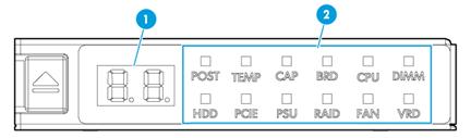
|
(1) Error code |
(2) LEDs |
For more information about the LEDs and error codes, see "LEDs."
LEDs
POST LED
|
LED status |
Error code |
Description |
|
Steady green |
Code for the current POST phase (in the range of 00 to 99) |
The server is performing POST without detecting any error. |
|
Flashing red |
The POST process encountered an error and stopped in the displayed phase. |
|
|
Off |
00 |
The server is operating correctly when the error code is 00 and all LEDs are off. |
TEMP LED
|
LED status |
Error code |
Description |
|
Flashing amber (1 Hz) |
Temperature sensor ID |
A major temperature alarm is present on the component monitored by the sensor. This alarm occurs when the temperature of the component has exceeded the upper major alarm threshold or dropped below the lower major alarm threshold. |
|
Flashing red (1 Hz) |
Temperature sensor ID |
A critical temperature alarm is present on the component monitored by the sensor. This alarm occurs when the temperature of the component has exceeded the upper critical alarm threshold or dropped below the lower critical alarm threshold. |
CAP LED
|
LED status |
Error code |
Description |
|
Flashing amber |
01 |
The system power consumption has exceeded the power cap value. |
Component LEDs
An alarm is present if a component LED has one of the following behaviors:
· Flashing amber (1 Hz)—A major alarm has occurred.
· Flashing red (1 Hz)—A critical alarm has occurred.
Use Table 59 to identify the faulty item if a component LED has one of those behaviors. To obtain records of component status changes, use the event log in HDM. For information about using the event log, see HDM online help.
Table 59 LED, error code and faulty item matrix
|
LED |
Error code |
Faulty item |
|
BRD |
11 |
System board |
|
21 |
· Drive backplane in bay 1 (8SFF server) · Front backplane (non-8SFF servers) |
|
|
22 |
Drive backplane in drive cage bay 2 (8SFF server) |
|
|
23 |
Drive backplane in drive cage bay 3 (8SFF server) |
|
|
31 |
Rear 2LFF/4LFF drive backplane |
|
|
32 |
Rear 2SFF/4SFF drive backplane |
|
|
71 |
Mezzanine storage controller power |
|
|
81 |
Reserved |
|
|
91 |
mLOM Ethernet adapter |
|
|
NOTE: If the error code field displays 11 and any other code alternatively, replace the faulty item other than the system board. If the issue persists, replace the system board. |
||
|
CPU (processor) |
01 |
Processor 1 |
|
02 |
Processor 2 |
|
|
DIMM |
A1 through A9, AA, AC, or AE |
· A1 through A9—DIMMs in slots A1 through A9 · AA—DIMM in slot A10 · AC—DIMM in slot A11 · AE—DIMM in slot A12 |
|
b1 through b9, bA, bC, or bE |
· b1 through b9—DIMMs in slots B1 through B9 · bA—DIMM in slot B10 · bC—DIMM in slot B11 · bE—DIMM in slot B12 |
|
|
HDD |
00 through 07 |
Relevant front drive (8LFF server) |
|
10 through 17 |
Relevant drive in bay 1 (8SFF server) |
|
|
20 through 27 |
Relevant drive in bay 2 (8SFF server) |
|
|
30 through 37 |
Relevant drive in bay 3 (8SFF server) |
|
|
00 through 11 |
Relevant front drive (12LFF server) |
|
|
20 through 29 |
Relevant rear drive (12LFF server) |
|
|
00 through 24 |
Relevant front drive (25SFF server) |
|
|
30 through 39 |
Relevant rear drive (25SFF server) |
|
|
PCIE |
01 through 08 |
PCIe modules in PCIe slots 1 to 8 of the riser card |
|
PSU |
01 |
Power supply 1 |
|
02 |
Power supply 2 |
|
|
RAID |
10 |
Mezzanine storage controller status |
|
FAN |
01 through 06 |
Fan 1 through Fan 6 |
|
VRD |
01 |
System board P5V voltage |
|
02 |
System board P1V05 PCH voltage |
|
|
03 |
System board PVCC HPMOS voltage |
|
|
04 |
System board P3V3 voltage |
|
|
05 |
System board P1V8 PCH voltage |
|
|
06 |
System board PVCCIO processor 1 voltage |
|
|
07 |
System board PVCCIN processor 1 voltage |
|
|
08 |
System board PVCCIO processor 2 voltage |
|
|
09 |
System board PVCCIN processor 2 voltage |
|
|
10 |
System board VPP processor 1 ABC voltage |
|
|
11 |
System board VPP processor 1 DEF voltage |
|
|
12 |
System board VDDQ processor 1 ABC voltage |
|
|
13 |
System board VDDQ processor 1 DEF voltage |
|
|
14 |
System board VTT processor 1 ABC voltage |
|
|
15 |
System board VTT processor 1 DEF voltage |
|
|
16 |
System board VPP processor 1 ABC voltage |
|
|
17 |
System board VPP processor 1 DEF voltage |
|
|
18 |
System board VDDQ processor 2 ABC voltage |
|
|
19 |
System board VDDQ processor 2 DEF voltage |
|
|
20 |
System board VTT processor 2 ABC voltage |
|
|
21 |
System board VTT processor 2 DEF voltage |
|
Fiber transceiver modules
|
Model |
Central wavelength |
Connector |
Max transmission distance |
|
SFP-XG-SX-MM850-A1-X |
850 nm |
LC |
300 m (984.25 ft) |
|
SFP-XG-SX-MM850-E1-X |
850 nm |
LC |
300 m (984.25 ft) |
|
SFP-25G-SR-MM850-1-X |
850 nm |
LC |
100 m (328.08 ft) |
|
SFP-GE-SX-MM850-A |
850 nm |
LC |
550 m (1804.46 ft) |
|
QSFP-100G-SR4-MM850 |
850 nm |
MPO |
100 m (328.08 ft) |
|
SFP-XG-LX-SM1310-E |
1310 nm |
LC |
10000 m (32808.40 ft) |
|
QSFP-40G-SR4-MM850 |
850 nm |
MPO |
100 m (328.08 ft) |
Storage options other than HDDs and SDDs
|
Model |
Specifications |
|
SD-32G-Micro-A |
32 GB microSD mainstream flash media kit module |
|
DVD-RW-Mobile-USB-A |
Removable USB DVDRW drive module
For this module to work correctly, you must connect it to a USB 3.0 connector. |
|
DVD-RW-SATA-9.5MM-A |
9.5mm SATA DVD-RW optical drive |
|
DVD-ROM-SATA-9.5MM-A |
9.5mm SATA DVD-ROM optical drive |
NVMe VROC modules
|
Model |
RAID levels |
Compatible NVMe drives |
|
NVMe-VROC-Key-S |
0, 1, 10 |
All NVMe drives |
|
NVMe-VROC-Key-P |
0, 1, 5, 10 |
All NVMe drives |
|
NVMe-VROC-Key-i |
0, 1, 5, 10 |
Intel NVMe drives |
TPM/TCM modules
Trusted platform module (TPM) is a microchip embedded in the system board. It stores encryption information (such as encryption keys) for authenticating server hardware and software. The TPM operates with drive encryption programs such as Microsoft Windows BitLocker to provide operating system security and data protection. For information about Microsoft Windows BitLocker, visit the Microsoft website at http://www.microsoft.com.
Trusted cryptography module (TCM) is a trusted computing platform-based hardware module with protected storage space, which enables the platform to implement password calculation.
Table 60 describes the TPM and TCM modules supported by the server.
Table 60 TPM/TCM specifications
|
Model |
Specifications |
|
TPM-2-X |
Trusted Platform Module 2.0 |
|
TCM-1-X |
Trusted Cryptography Module 1.0 |
Security bezels, slide rail kits, and cable management brackets
|
Description |
|
|
CMA-2U-A |
2U cable management bracket |
|
SL-2U-FR |
2U standard rail |
|
SEC-Panel-2U-G3-X |
2U security bezel |
|
BF-P100-B |
24DIMM P100 air baffle kit |
|
UIS-SDR-ToHK-UIS-Cell-3000-G3 |
H3C UIS-Cell 3000 G3 special delivery to Hongkong module |
Appendix C Hot removal and managed hot removal of NVMe drives
Hot removal and managed hot removal of NVMe drives enables you to remove NVMe drives safely while the server is operating.
The hot removal and managed hot removal of NVMe drives depend on the VMD status and the operating system. For more information about VMD, see the BIOS user guide for the server.
VMD Auto and VMD Enabled
Operating systems supporting hot removal and managed hot removal of NVMe drives
If your server uses Intel Skylake processors, see Table 61 for operating systems that support hot removal and managed hot removal of NVMe drives.
If your server uses Intel Cascade Lake processors, see Table 62 for operating systems that support hot removal and managed hot removal of NVMe drives.
Operating systems not listed in Table 61 and Table 62 do not support hot removal and managed hot removal of NVMe drives. To remove NVMe drives, you must first power off the server.
|
Operating system |
|
Windows |
|
Windows Server 2012R2 |
|
Windows Server 2016 |
|
Windows Server 2019 |
|
Red Hat Enterprise Linux 7.3 |
|
Red Hat Enterprise Linux 7.4 |
|
Red Hat Enterprise Linux 7.5 |
|
Red Hat Enterprise Linux 7.6 |
|
SUSE 12Sp4 |
|
SUSE 15 |
|
HyperVisors |
|
VMware ESXi 6.5 |
|
VMware ESXi 6.5 U1 |
|
VMware ESXi 6.5 U2 |
|
VMware ESXi 6.7 |
|
VMware ESXi 6.7 U1 |
|
Operating system |
|
Windows |
|
Windows Server 2016 |
|
Windows Server 2019 |
|
Linux |
|
Red Hat Enterprise Linux 7.5 |
|
Red Hat Enterprise Linux 7.6 |
|
SUSE 12Sp4 |
|
SUSE 15 |
|
HyperVisors |
|
VMware ESXi 6.5 U2 |
|
VMware ESXi 6.7 |
|
VMware ESXi 6.7 U1 |
Performing a managed hot removal in Windows
Prerequisites
Install Intel® Rapid Storage Technology enterprise (Intel® RSTe).
To obtain Intel® RSTe, use one of the following methods:
· Go to https://platformsw.intel.com/KitSearch.aspx to download the software.
· Contact Intel Support.
Procedure
1. Stop reading data from or writing data to the NVMe drive to be removed.
2. Identify the location of the NVMe drive. For more information, see "Drive configurations and numbering."
3. Run Intel® RSTe.
4. Unmount the NVMe drive from the operating system, as shown in Figure 311:
¡ Select the NVMe drive to be removed.
¡ Click Activate LED to turn on the Fault/UID LED on the drive.
¡ Click Remove Disk.
Figure 311 Removing an NVMe drive
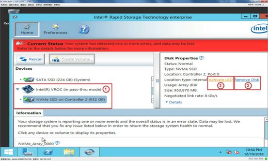
5. Observe the Fault/UID LED on the drive. If the Fault/UID LED turns steady blue and the drive is removed from the Devices list, remove the drive from the server.
For more information about the removal procedure, see "Replacing an NVMe drive."
Performing a managed hot removal in Linux
In Linux, you can perform a managed hot removal of NVMe drives from the CLI or by using Intel® Accelerated Storage Manager.
Prerequisites
· Identify that your operating system is a non-SLES Linux operating system. SLES operating systems do not support managed hot removal of NVMe drives.
· To perform a managed hot removal by using Intel® ASM, install Intel® ASM.
To obtain Intel® ASM, use one of the following methods:
¡ Go to https://platformsw.intel.com/KitSearch.aspx to download the software.
¡ Contact Intel Support.
Performing a managed hot removal from the CLI
1. Stop reading data from or writing data to the NVMe drive to be removed.
2. Identify the location of the NVMe drive. For more information, see "Drive configurations and numbering."
3. Access the CLI of the server.
4. Execute the lsblk | grep nvme command to identify the drive letter of the NVMe drive, as shown in Figure 312.
Figure 312 Identifying the drive letter of the NVMe drive to be removed
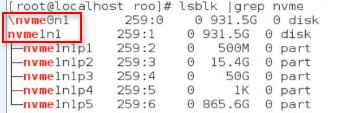
5. Execute the ledctl locate=/dev/drive_letter command to turn on the Fault/UID LED on the drive. The drive_letter argument represents the drive letter, for example, nvme0n1.
6. Execute the echo 1 > /sys/block/drive_letter/device/device/remove command to unmount the drive from the operating system. The drive_letter argument represents the drive letter, for example, nvme0n1.
7. Observe the Fault/UID LED on the drive. If the Fault/UID LED turns steady blue, remove the drive from the server.
For more information about the removal procedure, see "Replacing an NVMe drive."
Performing a managed hot removal from the Intel® ASM Web interface
1. Stop reading data from or writing data to the NVMe drive to be removed.
2. Identify the location of the NVMe drive. For more information, see "Drive configurations and numbering."
3. Run Intel® ASM.
4. Click RSTe Management.
Figure 313 Accessing RSTe Management
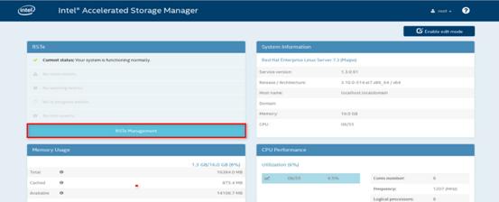
5. Expand the Intel(R) VROC(in pass-thru mode) menu to view operating NVMe drives, as shown in Figure 314.
Figure 314 Viewing operating NVMe drives
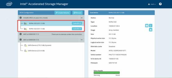
6. Click the light bulb icon to turn on the Fault/UID LED on the drive, as shown in Figure 315.
Figure 315 Turning on the drive Fault/UID LED
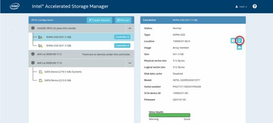
7. After the Fault/UID LED for the NVMe drive turns steady blue, click the removal icon, as shown in Figure 316.
Figure 316 Removing an NVMe drive
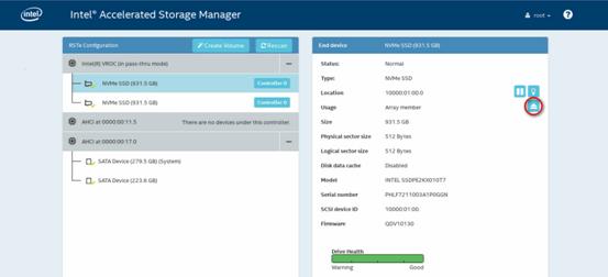
8. In the confirmation dialog box that opens, click Yes.
Figure 317 Confirming the removal
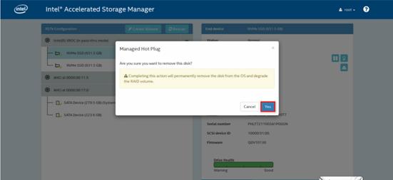
9. Remove the drive from the server. For more information about the removal procedure, see "Replacing an NVMe drive."
VMD Disabled
For managed hot removal of NVMe drives, contact the support.
Appendix D Environment requirements
About environment requirements
The operating temperature requirements for the server vary depending on the server model and hardware configuration. When the general and component-based requirements conflict, use the component-based requirement.
Be aware that the actual maximum operating temperature of the server might be lower than what is stated because of poor site cooling performance. In a real data center, the server cooling performance might decrease because of adverse external factors, including poor cabinet cooling performance, high power density inside the cabinet, or insufficient spacing between devices.
General environment requirements
|
Item |
Specifications |
|
Operating temperature |
Minimum: 5°C (41°F) Maximum: Varies depending on the power consumed by the processors and presence of expansion modules. For more information, see "Operating temperature requirements." |
|
Storage temperature |
–40°C to +70°C (–40°F to +158°F) |
|
Operating humidity |
8% to 90%, noncondensing |
|
Storage humidity |
5% to 90%, noncondensing |
|
Operating altitude |
–60 m to +3000 m (–196.85 ft to +9842.52 ft) The allowed maximum temperature decreases by 0.33 °C (32.59°F) as the altitude increases by 100 m (328.08 ft) from 900 m (2952.76 ft) |
|
Storage altitude |
–60 m to +5000 m (–196.85 ft to +16404.20 ft) |
Operating temperature requirements
General guidelines
You must install six fans if you are using GPU module other than GPU-M2000 and GPU-M4000-1-X.
Performance of the following hardware components might degrade if one fan fails or is absent:
· Processors 8180, 8180M, 8168, 6154, 6146, 6144, 6254, 6244, 6240Y, and 6252N.
· GPU modules.
· SATA M.2 SSDs.
· DCPMMs.
8SFF server with an 8SFF drive configuration
Use Table 63 to determine the maximum operating temperature of the 8SFF server that uses an 8SFF drive configuration. A maximum server operating temperature applies if the server contains any options in its matching hardware option list.
If a single fan fails, the maximum server operating temperature drops by 5°C (41°F) and cannot exceed 35°C (95°F).
|
|
NOTE: All maximum server operating temperature values are provided on the basis that the fans are installed as needed and operating correctly. For more information about fan configurations, see the guidelines in "Installing fans." |
Table 63 Temperature requirements for the 8SFF server with an 8SFF drive configuration
|
Maximum server operating temperature |
Hardware options |
|
30°C (86°F) |
GPU modules: · GPU-P100. · GPU-V100-32G. · GPU-V100. |
|
Any of the following GPU modules used with 165W (or higher) processors: · GPU-K80-1. · GPU-M60-1-X. · GPU-P40-X. |
|
|
35°C (95°F) |
· Samsung NVMe drives. · DCPMMs. · NVMe SSD PCIe accelerator module. · Rear SATA M.2 SSD. · DPS-1600AB-13 R power supply. · Any of the following GPU modules used with less than 165W processors: ¡ GPU-K80-1. ¡ GPU-M60-1-X. ¡ GPU-P40-X. |
|
40°C (104°F) |
· 15000 RPM HDDs and four operating fans. · 10000 RPM 1.2 TB (or higher) HDDs and four operating fans. · NVMe drives, excluding Samsung NVMe drives. · 64 GB LRDIMMs and a faulty fan. · Ethernet adapter IB-MCX453A-FCAT-56/40Gb-1P or IB-MCX453A-FCAT-56/40Gb-1P-1. · DPS-1300AB-6 R power supply. · GPU modules: ¡ GPU-P4-X. ¡ GPU-M4-1. ¡ GPU-M10-X. ¡ GPU-T4. ¡ GPU-MLU100-D3. |
|
· Supercapacitor. · Processor 8180, 8180M, 8168, 6154, 6146, 6144, 6254, 6244, 6240Y, or 6252N. · 15000 RPM HDDs and six operating fans. · 10000 RPM 1.2 TB (or higher) HDDs and six operating fans. |
|
|
50°C (122°F) |
None of the above hardware options or operating conditions exists. |
8SFF server with a 16SFF/24SFF drive configuration
Use Table 64 to determine the maximum operating temperature of the 8SFF server with a 16SFF/24SFF drive configuration. A maximum server operating temperature applies if the server contains any options in its matching hardware option list.
If a single fan fails, the maximum server operating temperature drops by 5°C (41°F) and cannot exceed 35°C (95°F).
|
|
NOTE: All maximum server operating temperature values are provided on the basis that the fans are installed as needed and operating correctly. For more information about fan configurations, see the guidelines in "Installing fans." |
Table 64 Temperature requirements for the 8SFF server with a 16SFF/24SFF drive configuration
|
Hardware options |
|
|
20°C (68°F) |
GPU-P100, GPU-V100-32G, or GPU-V100 in a 24SFF NVMe drive configuration that uses NVMe drives with a 3.2TB capacity (or larger). |
|
22°C (71.6°F) |
Any of the following GPU modules in a 16SFF or 24SFF drive configuration that uses 165W (or higher) processors and NVMe drives with a 3.2TB capacity (or larger): · GPU-K80-1. · GPU-M60-1-X. · GPU-P40-X. |
|
25°C (77°F) |
· GPU module GPU-P100, GPU-V100-32G, or GPU-V100 in any of the following drive configurations: ¡ 16SFF (8SFF SAS/SATA+8SFF NVMe, or 16SFF NVMe) with NVMe drives that have a 3.2TB capacity (or larger). ¡ 24SFF NVMe, without NVMe drives that have a 3.2TB capacity (or larger). · Any of the following GPU modules in a 16SFF or 24SFF drive configuration that uses NVMe drives with a 3.2TB capacity (or larger): ¡ GPU-K80-1. ¡ GPU-M60-1-X. ¡ GPU-P40-X. |
|
27°C (80.6°F) |
Any of the following GPU modules used with 165W (or higher) processors (without NVMe drives that have a 3.2TB capacity or larger): · GPU-M60-1-X. · GPU-P40-X. |
|
30°C (86°F) |
¡ GPU-K80-1. ¡ GPU-M60-1-X. ¡ GPU-P40-X. · GPU module GPU-P4-X, GPU-M4-1, GPU-T4, or GPU-MLU100-D3 in a 16SFF or 24SFF drive configuration that uses NVMe drives with a 3.2TB capacity (or larger). · GPU module GPU-M10-X in a 24SFF drive configuration that uses NVMe drives with a 3.2TB capacity (or larger). · GPU module GPU-P100, GPU-V100-32G, GPU-V100 used with any of the following drive configurations: ¡ 16SFF SAS/SATA. ¡ 16SFF (8SFF SAS/SATA+8SFF NVMe, or 16SFF NVMe) without NVMe drives that have a 3.2TB capacity (or larger). |
|
35°C (95°F) |
· DCPMMs. · Samsung NVMe drives. · Rear drives. · NVMe SSD PCIe accelerator module. · Rear SATA M.2 SSD. · DPS-1600AB-13 R power supply. · GPU module GPU-P4-X, GPU-M4-1, GPU-T4, or GPU-MLU100-D3 in either of the following drive configurations: ¡ 16SFF or 24 SFF (only SAS/SATA). ¡ 16SFF or 24SFF (only NVMe or SAS/SATA+NVMe) that does not use NVMe drives with a 3.2TB capacity (or larger). · GPU module GPU-M10-X used with any of the following drive configurations: ¡ 24SFF NVMe without NVMe drives that have a 3.2TB capacity (or larger). ¡ 16SFF with NVMe drives that have a 3.2TB capacity (or larger). |
|
40°C (104°F) |
· 15000 RPM HDDs and four operating fans. · 10000 RPM 1.2 TB (or higher) HDDs and four operating fans. · NVMe drives, excluding Samsung NVMe drives. · Ethernet adapter IB-MCX453A-FCAT-56/40Gb-1P or IB-MCX453A-FCAT-56/40Gb-1P-1. · DPS-1300AB-6 R power supply. · GPU module GPU-M10-X used with any of the following drive configurations: ¡ 16SFF SAS/SATA. ¡ 16SFF (8SFF SAS/SATA+8SFF NVMe, or 16SFF NVMe) without NVMe drives that have a 3.2TB capacity (or larger). |
|
45°C (113°F) |
None of the above hardware options or operating conditions exists. |
25SFF server with any drive configuration
Use Table 65 to determine the maximum operating temperature of the 25SFF server with any drive configuration. A maximum server operating temperature applies if the server contains any options in its matching hardware option list.
If a single fan fails, the maximum server operating temperature drops by 5°C (41°F) and cannot exceed 35°C (95°F).
|
|
NOTE: All maximum server operating temperature values are provided on the basis that the fans are installed as needed and operating correctly. For more information about fan configurations, see the guidelines in "Installing fans." |
Table 65 Temperature requirements for the 25SFF server with any drive configuration
|
Maximum server operating temperature |
Hardware options |
|
25°C (77°F) |
GPU modules: · GPU-P100. · GPU-V100-32G. · GPU-V100. |
|
Any of the following GPU modules used with 165W (or higher) processors: · GPU-K80-1. · GPU-M60-1-X. · GPU-P40-X. |
|
|
30°C (86°F) |
Any of the following GPU modules used with less than 165W processors: · GPU-K80-1. · GPU-M60-1-X. · GPU-P40-X. |
|
35°C (95°F) |
· DCPMMs. · Samsung NVMe drives. · Rear drives. · NVMe SSD PCIe accelerator module. · Rear SATA M.2 SSD. · DPS-1600AB-13 R power supply. ¡ GPU-P4-X. ¡ GPU-M4-1. ¡ GPU-T4. ¡ GPU-MLU100-D3. ¡ GPU-M10-X. |
|
40°C (104°F) |
· 15000 RPM HDDs and four operating fans. · 10000 RPM 1.2 TB (or higher) HDDs and four operating fans. · NVMe drives, excluding Samsung NVMe drives. · Ethernet adapter IB-MCX453A-FCAT-56/40Gb-1P or IB-MCX453A-FCAT-56/40Gb-1P-1. · DPS-1300AB-6 R power supply. |
|
45°C (113°F) |
None of the above hardware options or operating conditions exists. |
8LFF server with any drive configuration
Use Table 66 to determine the maximum operating temperature of the 8LFF server. A maximum server operating temperature applies if the server contains any options in its matching hardware option list.
If a single fan fails, the maximum server operating temperature drops by 5°C (41°F) and cannot exceed 35°C (95°F).
|
|
NOTE: All maximum server operating temperature values are provided on the basis that the fans are installed as needed and operating correctly. For more information about fan configurations, see the guidelines in "Installing fans." |
Table 66 Temperature requirements for the 8LFF server with any drive configuration
|
Maximum server operating temperature |
Hardware options |
|
30°C (86°F) |
GPU modules: · GPU-P100. · GPU-V100-32G. · GPU-V100. |
|
Any of the following GPU modules used with 165W (or higher) processors: · GPU-K80-1. · GPU-M60-1-X. · GPU-P40-X. |
|
|
35°C (95°F) |
· DCPMMs. · NVMe SSD PCIe accelerator module. · Rear SATA M.2 SSD. · DPS-1600AB-13 R power supply. · Any of the following GPU modules used with less than 165W processors: ¡ GPU-K80-1. ¡ GPU-M60-1-X. ¡ GPU-P40-X. |
|
40°C (104°F) |
· Ethernet adapter IB-MCX453A-FCAT-56/40Gb-1P or IB-MCX453A-FCAT-56/40Gb-1P-1. · DPS-1300AB-6 R power supply. · GPU modules: ¡ GPU-P4-X. ¡ GPU-M4-1. ¡ GPU-T4. ¡ GPU-MLU100-D3. ¡ GPU-M10-X. |
|
45°C (113°F) |
None of the above hardware options or operating conditions exists. |
12LFF server with any drive configuration
Use Table 67 to determine the maximum operating temperature of the 12LFF server. A maximum server operating temperature applies if the server contains any options in its matching hardware option list.
If a single fan fails, the maximum server operating temperature drops by 5°C (41°F) and cannot exceed 35°C (95°F).
|
|
NOTE: All maximum server operating temperature values are provided on the basis that the fans are installed as needed and operating correctly. For more information about fan configurations, see the guidelines in "Installing fans." |
Table 67 Temperature requirements for the 12LFF server with any drive configuration
|
Maximum server operating temperature |
Hardware options |
|
22°C (71.6°F) |
Any of the following GPU modules used with 165W (or higher) processors: · GPU-K80-1. · GPU-M60-1-X. · GPU-P40-X. |
|
25°C (77°F) |
· GPU modules: ¡ GPU-P100. ¡ GPU-V100-32G. ¡ GPU-V100. · Any of the following GPU modules used with less than 165W processors: ¡ GPU-K80-1. ¡ GPU-M60-1-X. ¡ GPU-P40-X. |
|
35°C (95°F) |
· DCPMM. · Samsung NVMe drives. · Rear drives. · NVMe SSD PCIe accelerator module. · Rear SATA M.2 SSD. · DPS-1600AB-13 R power supply. · GPU modules: ¡ GPU-P4-X. ¡ GPU-M4-1. ¡ GPU-T4. ¡ GPU-MLU100-D3. ¡ GPU-M10-X. |
|
40°C (104°F) |
· NVMe drives, excluding Samsung NVMe drives. · Ethernet adapter IB-MCX453A-FCAT-56/40Gb-1P or IB-MCX453A-FCAT-56/40Gb-1P-1. · DPS-1300AB-6 R power supply. |
|
45°C (113°F) |
None of the above hardware options or operating conditions exists. |
Appendix E Product recycling
New H3C Technologies Co., Ltd. provides product recycling services for its customers to ensure that hardware at the end of its life is recycled. Vendors with product recycling qualification are contracted to New H3C to process the recycled hardware in an environmentally responsible way.
For product recycling services, contact New H3C at
· Tel: 400-810-0504
· E-mail: service@h3c.com
· Website: http://www.h3c.com
Appendix F Glossary
|
Description |
|
|
B |
|
|
BIOS |
Basic input/output system is non-volatile firmware pre-installed in a ROM chip on a server's system board. The BIOS stores basic input/output, power-on self-test, and auto startup programs to provide the most basic hardware initialization, setup and control functionality. |
|
C |
|
|
CPLD |
Complex programmable logic device is an integrated circuit used to build reconfigurable digital circuits. |
|
E |
|
|
Ethernet adapter |
An Ethernet adapter, also called a network interface card (NIC), connects the server to the network. |
|
F |
|
|
FIST |
Fast Intelligent Scalable Toolkit provided by H3C for easy and extensible server management. It can guide users to configure a server quickly with ease and provide an API interface to allow users to develop their own management tools. |
|
G |
|
|
GPU module |
Graphics processing unit module converts digital signals to analog signals for output to a display device and assists processors with image processing to improve overall system performance. |
|
H |
|
|
HDM |
H3C Device Management is the server management control unit with which administrators can configure server settings, view component information, monitor server health status, and remotely manage the server. |
|
A module that supports hot swapping (a hot-swappable module) can be installed or removed while the server is running without affecting the system operation. |
|
|
K |
|
|
KVM |
A device that allows remote users to use their local video display, keyboard, and mouse to monitor and control remote servers. |
|
N |
|
|
NVMe SSD expander module |
An expander module that facilitates communication between the system board and the front NVMe hard drives. The module is required if a front NVMe hard drive is installed. |
|
NVMe VROC module |
A module that works with VMD to provide RAID capability for the server to virtualize storage resources of NVMe drives. |
|
R |
|
|
RAID |
Redundant array of independent disks (RAID) is a data storage virtualization technology that combines multiple physical hard drives into a single logical unit to improve storage and security performance. |
|
Redundancy |
A mechanism that ensures high availability and business continuity by providing backup modules. In redundancy mode, a backup or standby module takes over when the primary module fails. |
|
S |
|
|
Security bezel |
A locking bezel mounted to the front of a server to prevent unauthorized access to modules such as hard drives. |
|
U |
A unit of measure defined as 44.45 mm (1.75 in) in IEC 60297-1. It is used as a measurement of the overall height of racks, as well as equipment mounted in the racks. |
|
VMD |
VMD provides hot removal, management, and fault-tolerance functions for NVMe drives to increase availability, reliability, and serviceability. |
Appendix G Acronyms
|
Acronym |
Full name |
|
B |
|
|
BIOS |
|
|
C |
|
|
CMA |
Cable Management Arm |
|
CPLD |
Complex Programmable Logic Device |
|
D |
|
|
DCPMM |
Data Center Persistent Memory Module |
|
DDR |
Double Data Rate |
|
DIMM |
Dual In-Line Memory Module |
|
DRAM |
Dynamic Random Access Memory |
|
F |
|
|
FIST |
|
|
G |
|
|
GPU |
Graphics Processing Unit |
|
H |
|
|
HBA |
Host Bus Adapter |
|
HDD |
Hard Disk Drive |
|
HDM |
|
|
I |
|
|
IDC |
Internet Data Center |
|
K |
|
|
KVM |
Keyboard, Video, Mouse |
|
L |
|
|
LFF |
Large Form Factor |
|
LRDIMM |
Load Reduced Dual Inline Memory Module |
|
M |
|
|
mLOM |
Modular LAN-on-Motherboard |
|
N |
|
|
NCSI |
Network Controller Sideband Interface |
|
NVMe |
Non-Volatile Memory Express |
|
P |
|
|
PCIe |
Peripheral Component Interconnect Express |
|
PDU |
Power Distribution Unit |
|
POST |
Power-On Self-Test |
|
R |
|
|
RDIMM |
Registered Dual Inline Memory Module |
|
S |
|
|
SAS |
Serial Attached Small Computer System Interface |
|
SATA |
Serial ATA |
|
SD |
Secure Digital |
|
SDS |
Secure Diagnosis System |
|
SFF |
Small Form Factor |
|
SSD |
Solid State Drive |
|
T |
|
|
TCM |
Trusted Cryptography Module |
|
TDP |
Thermal Design Power |
|
TPM |
Trusted Platform Module |
|
U |
|
|
UID |
Unit Identification |
|
UPI |
Ultra Path Interconnect |
|
UPS |
Uninterruptible Power Supply |
|
USB |
Universal Serial Bus |
|
V |
|
|
VROC |
Virtual RAID on CPU |
|
VMD |
Volume Management Device |
