- Table of Contents
- Related Documents
-
| Title | Size | Download |
|---|---|---|
| 02-S12500_VPLS_Configuration_Examples | 557.69 KB |
Contents
Example: Configuring LDP VPLS instances
Example: Configuring BGP VPLS instances
Example: Configuring H-VPLS with LSP access
Example: Configuring BFD for H-VPLS
Example: Configuring hub-spoke VPLS
Introduction
This document provides VPLS configuration examples.
Virtual Private LAN Service (VPLS) delivers point-to-multipoint L2VPN services over an MPLS or IP backbone. The provider backbone emulates a switch to connect all geographically dispersed sites for each customer network. The backbone is transparent to the customer sites, which can communicate with each other as if they were on the same LAN.
VPLS has two networking models: full mesh and H-VPLS.
The full mesh model supports the following signaling protocols:
· LDP—Applies to the scenario where customer sites are a few and fixed.
· BGP—Applies to the scenario where customer sites are many and new sites will be added.
The H-VPLS model supports the following access modes:
· LSP access—Applies to the scenario where the devices connected to customer sites support MPLS. In this mode, customer packets directly enter the LSP tunnel.
· QinQ access—Applies to the scenario where the devices connected to customer sites do not support MPLS. In this mode, customer packets are added with an outer VLAN tag before they enter the LSP tunnel.
Prerequisites
The configuration examples in this document were created and verified in a lab environment, and all the devices were started with the factory default configuration. When you are working on a live network, make sure you understand the potential impact of every command on your network.
This document assumes that you have basic knowledge of VPLS.
Example: Configuring LDP VPLS instances
Network requirements
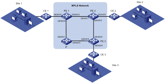
As shown in Figure 1, a customer has three sites connected to different CEs and will not add new sites.
Configure LDP VPLS instances on the PEs so that the customer sites can communicate in VLAN 1000 over the MPLS backbone.
|
Device |
Interface |
IP address |
Device |
Interface |
IP address |
|
PE1 |
Loopback0 |
192.0.0.1/32 |
P |
Loopback0 |
192.0.0.4/32 |
|
|
GE6/0/2 (VLAN 12) |
192.12.0.1/24 |
|
GE6/0/1 (VLAN 14) |
192.14.0.4/24 |
|
|
GE6/0/4 (VLAN 14) |
192.14.0.1/24 |
|
GE6/0/3 (VLAN 34) |
192.34.0.4/24 |
|
|
GE6/0/5 (VLAN 1000) |
|
|
|
|
|
PE2 |
Loopback0 |
192.0.0.2/32 |
PE3 |
Loopback0 |
192.0.0.3/32 |
|
|
GE4/0/1 (VLAN 12) |
192.12.0.2/24 |
|
GE4/0/2 (VLAN 23) |
192.23.0.3/24 |
|
|
GE4/0/3 (VLAN 23) |
192.23.0.2/24 |
|
GE4/0/4 (VLAN 34) |
192.34.0.3/24 |
|
|
GE4/0/5 (VLAN 1000) |
|
|
GE4/0/5 (VLAN 1000) |
|
Requirements analysis
To establish public LSPs between PEs, enable MPLS and LDP on all PE and P devices.
To transmit private labels between PEs, create VPLS instances and specify the peer PEs as LDP peers on the PEs.
To differentiate private data, configure match criteria on the PEs' interfaces connected to CEs. In this example, configure a match criterion to permit packets with VLAN ID 1000 so that the customer sites can communicate within VLAN 1000 over the MPLS backbone.
Software version used
This configuration example was created and verified on S12500-CMW520-R1825P01.
Configuration procedures
Configuring PE 1
1. Configure interfaces and assign IP addresses.
# Configure the interface connected to PE 2.
<Sysname> system-view
[Sysname] sysname PE1
[PE1] vlan 12
[PE1-vlan12] port GigabitEthernet 6/0/2
[PE1-vlan12] quit
[PE1] interface vlan-interface 12
[PE1-Vlan-interface12] ip address 192.12.0.1 24
[PE1-Vlan-interface12] undo shutdown
[PE1-Vlan-interface12] quit
[PE1] interface GigabitEthernet 6/0/2
[PE1-GigabitEthernet6/0/2] undo shutdown
[PE1-GigabitEthernet6/0/2] quit
# Configure the interface connected to P.
[PE1] vlan 14
[PE1-vlan14] port GigabitEthernet 6/0/4
[PE1-vlan14] quit
[PE1] interface vlan-interface 14
[PE1-Vlan-interface14] ip address 192.14.0.1 24
[PE1-Vlan-interface14] undo shutdown
[PE1-Vlan-interface14] quit
[PE1] interface GigabitEthernet 6/0/4
[PE1-GigabitEthernet6/0/4] undo shutdown
[PE1-GigabitEthernet6/0/4] quit
# Configure the loopback interface of PE 1.
[PE1] interface LoopBack 0
[PE1-LoopBack0] ip address 192.0.0.1 32
[PE1-LoopBack0] quit
2. Configure the IGP protocol:
# Configure the router ID.
[PE1] router id 192.0.0.1
# Configure OSPF to advertise routes.
[PE1] ospf 1
[PE1-ospf-1] area 0
[PE1-ospf-1-area-0.0.0.0] network 192.12.0.0 0.0.0.255
[PE1-ospf-1-area-0.0.0.0] network 192.14.0.0 0.0.0.255
[PE1-ospf-1-area-0.0.0.0] network 192.0.0.1 0.0.0.0
[PE1-ospf-1-area-0.0.0.0] quit
[PE1-ospf-1] quit
3. Configure basic MPLS:
# Configure the MPLS LSR ID, and enable MPLS, MPLS LDP, and MPLS L2VPN globally.
[PE1] mpls lsr-id 192.0.0.1
[PE1] mpls
[PE1-mpls] quit
[PE1] mpls ldp
[PE1-mpls-ldp] quit
[PE1] mpls l2vpn
# Enable MPLS and MPLS LDP on the VLAN interfaces.
[PE1] interface vlan-interface 12
[PE1-Vlan-interface12] mpls
[PE1-Vlan-interface12] mpls ldp
[PE1-Vlan-interface12] quit
[PE1] interface vlan-interface 14
[PE1-Vlan-interface14] mpls
[PE1-Vlan-interface14] mpls ldp
[PE1-Vlan-interface14] quit
4. Configure the remote LDP sessions.
[PE1] mpls ldp remote-peer 2
[PE1-mpls-remote2] remote-ip 192.0.0.2
[PE1-mpls-remote2] quit
[PE1] mpls ldp remote-peer 3
[PE1-mpls-remote3] remote-ip 192.0.0.3
[PE1-mpls-remote3] quit
5. Configure VPLS:
# Configure LDP VPLS instance vpn1000.
[PE1] vsi vpn1000 static
[PE1-vsi-vpn1000] pwsignal ldp
[PE1-vsi-vpn1000-ldp] vsi-id 1000
# Configure the PWs to PE 2 and PE 3.
[PE1-vsi-vpn1000-ldp] peer 192.0.0.2
[PE1-vsi-vpn1000-ldp] peer 192.0.0.3
[PE1-vsi-vpn1000-ldp] quit
[PE1-vsi-vpn1000] quit
# Bind the VPLS instance to the AC.
[PE1] vlan 1000
[PE1-vlan1000] quit
[PE1] interface GigabitEthernet 6/0/5
[PE1-GigabitEthernet6/0/5] port link-type trunk
[PE1-GigabitEthernet6/0/5] port trunk permit vlan 1000
Please wait... Done.
[PE1-GigabitEthernet6/0/5] service-instance 1000
[PE1-GigabitEthernet6/0/5-srv1000] encapsulation vlan 1000
[PE1-GigabitEthernet6/0/5-srv1000] xconnect vsi vpn1000
[PE1-GigabitEthernet6/0/5-srv1000] quit
[PE1-GigabitEthernet6/0/5] quit
Configuring PE 2
1. Configure interfaces and assign IP addresses.
# Configure the interface connected to PE 1.
<Sysname> system-view
[Sysname] sysname PE2
[PE2] vlan 12
[PE2-vlan12] port GigabitEthernet 4/0/1
[PE2-vlan12] quit
[PE2] interface vlan-interface 12
[PE2-Vlan-interface12] ip address 192.12.0.2 24
[PE2-Vlan-interface12] undo shutdown
[PE2-Vlan-interface12] quit
[PE2] interface GigabitEthernet 4/0/1
[PE2-GigabitEthernet4/0/1] undo shutdown
[PE2-GigabitEthernet4/0/1] quit
# Configure the interface connected to PE 3.
[PE2] vlan 23
[PE2-vlan23] port GigabitEthernet 4/0/3
[PE2-vlan23] quit
[PE2] interface vlan-interface 23
[PE2-Vlan-interface23] ip address 192.23.0.2 24
[PE2-Vlan-interface23] undo shutdown
[PE2-Vlan-interface23] quit
[PE2] interface GigabitEthernet 4/0/3
[PE2-GigabitEthernet4/0/3] undo shutdown
[PE2-GigabitEthernet4/0/3] quit
# Configure the loopback interface of PE 2.
[PE2] interface LoopBack 0
[PE2-LoopBack0] ip address 192.0.0.2 32
[PE2-LoopBack0] quit
2. Configure the IGP protocol:
# Configure the router ID.
[PE2] router id 192.0.0.2
# Configure OSPF to advertise routes.
[PE2] ospf 1
[PE2-ospf-1] area 0
[PE2-ospf-1-area-0.0.0.0] network 192.12.0.0 0.0.0.255
[PE2-ospf-1-area-0.0.0.0] network 192.23.0.0 0.0.0.255
[PE2-ospf-1-area-0.0.0.0] network 192.0.0.2 0.0.0.0
[PE2-ospf-1-area-0.0.0.0] quit
[PE2-ospf-1] quit
3. Configure basic MPLS:
# Configure the MPLS LSR ID, and enable MPLS, MPLS LDP, and MPLS L2VPN globally.
[PE2] mpls lsr-id 192.0.0.2
[PE2] mpls
[PE2-mpls] quit
[PE2] mpls ldp
[PE2-mpls-ldp] quit
[PE2] mpls l2vpn
# Enable MPLS and MPLS LDP on the VLAN interfaces.
[PE2] interface vlan-interface 12
[PE2-Vlan-interface12] mpls
[PE2-Vlan-interface12] mpls ldp
[PE2-Vlan-interface12] quit
[PE2] interface vlan-interface 23
[PE2-Vlan-interface23] mpls
[PE2-Vlan-interface23] mpls ldp
[PE2-Vlan-interface23] quit
4. Configure the remote LDP sessions.
[PE2] mpls ldp remote-peer 1
[PE2-mpls-remote1] remote-ip 192.0.0.1
[PE2-mpls-remote1] quit
[PE2] mpls ldp remote-peer 3
[PE2-mpls-remote3] remote-ip 192.0.0.3
[PE2-mpls-remote3] quit
5. Configure VPLS:
# Configure LDP VPLS instance vpn1000.
[PE2] vsi vpn1000 static
[PE2-vsi-vpn1000] pwsignal ldp
[PE2-vsi-vpn1000-ldp] vsi-id 1000
# Configure the PWs to PE 1 and PE 3.
[PE2-vsi-vpn1000-ldp] peer 192.0.0.1
[PE2-vsi-vpn1000-ldp] peer 192.0.0.3
[PE2-vsi-vpn1000-ldp] quit
[PE2-vsi-vpn1000] quit
# Bind the VPLS instance to the AC.
[PE2] vlan 1000
[PE2-vlan1000] quit
[PE2] interface GigabitEthernet 4/0/5
[PE2-GigabitEthernet4/0/5] port link-type trunk
[PE2-GigabitEthernet4/0/5] port trunk permit vlan 1000
Please wait... Done.
[PE2-GigabitEthernet4/0/5] service-instance 1000
[PE2-GigabitEthernet4/0/5-srv1000] encapsulation vlan 1000
[PE2-GigabitEthernet4/0/5-srv1000] xconnect vsi vpn1000
[PE2-GigabitEthernet4/0/5-srv1000] quit
[PE2-GigabitEthernet4/0/5] quit
Configuring PE 3
1. Configure interfaces and assign IP addresses.
# Configure the interface connected to PE 2.
<Sysname> system-view
[Sysname] sysname PE3
[PE3] vlan 23
[PE3-vlan23] port GigabitEthernet 4/0/2
[PE3-vlan23] quit
[PE3] interface vlan-interface 23
[PE3-Vlan-interface23] ip address 192.23.0.3 24
[PE3-Vlan-interface23] undo shutdown
[PE3-Vlan-interface23] quit
[PE3] interface GigabitEthernet 4/0/2
[PE3-GigabitEthernet4/0/2] undo shutdown
[PE3-GigabitEthernet4/0/2] quit
# Configure the interface connected to P.
[PE3] vlan 34
[PE3-vlan34] port GigabitEthernet 4/0/4
[PE3-vlan34] quit
[PE3] interface vlan-interface 34
[PE3-Vlan-interface34] ip address 192.34.0.3 24
[PE3-Vlan-interface34] undo shutdown
[PE3-Vlan-interface34] quit
[PE3] interface GigabitEthernet 4/0/4
[PE3-GigabitEthernet4/0/4] undo shutdown
[PE3-GigabitEthernet4/0/4] quit
# Configure the loopback interface of PE 3.
[PE3] interface LoopBack 0
[PE3-LoopBack0] ip address 192.0.0.3 32
[PE3-LoopBack0] quit
2. Configure the IGP protocol.
# Configure the router ID.
[PE3] router id 192.0.0.3
# Configure OSPF to advertise routes.
[PE3] ospf 1
[PE3-ospf-1] area 0
[PE3-ospf-1-area-0.0.0.0] network 192.23.0.0 0.0.0.255
[PE3-ospf-1-area-0.0.0.0] network 192.34.0.0 0.0.0.255
[PE3-ospf-1-area-0.0.0.0] network 192.0.0.3 0.0.0.0
[PE3-ospf-1-area-0.0.0.0] quit
[PE3-ospf-1] quit
3. Configure basic MPLS:
# Configure the MPLS LSR ID, and enable MPLS, MPLS LDP, and MPLS L2VPN globally.
[PE3] mpls lsr-id 192.0.0.3
[PE3] mpls
[PE3-mpls] quit
[PE3] mpls ldp
[PE3-mpls-ldp] quit
[PE3] mpls l2vpn
# Enable MPLS and MPLS LDP on the VLAN interfaces.
[PE3] interface vlan-interface 23
[PE3-Vlan-interface23] mpls
[PE3-Vlan-interface23] mpls ldp
[PE3-Vlan-interface23] quit
[PE3] interface vlan-interface 34
[PE3-Vlan-interface34] mpls
[PE3-Vlan-interface34] mpls ldp
[PE3-Vlan-interface34] quit
4. Configure the remote LDP sessions.
[PE3] mpls ldp remote-peer 1
[PE3-mpls-remote1] remote-ip 192.0.0.1
[PE3-mpls-remote1] quit
[PE3] mpls ldp remote-peer 2
[PE3-mpls-remote2] remote-ip 192.0.0.2
[PE3-mpls-remote2] quit
5. Configure VPLS:
# Configure LDP VPLS instance vpn1000.
[PE3] vsi vpn1000 static
[PE3-vsi-vpn1000] pwsignal ldp
[PE3-vsi-vpn1000-ldp] vsi-id 1000
# Configure the PWs to PE 1 and PE 2.
[PE3-vsi-vpn1000-ldp] peer 192.0.0.1
[PE3-vsi-vpn1000-ldp] peer 192.0.0.2
[PE3-vsi-vpn1000-ldp] quit
[PE3-vsi-vpn1000] quit
# Bind the VPLS instance to the AC.
[PE3] vlan 1000
[PE3-vlan1000] quit
[PE3] interface GigabitEthernet 4/0/5
[PE3-GigabitEthernet4/0/5] port link-type trunk
[PE3-GigabitEthernet4/0/5] port trunk permit vlan 1000
Please wait... Done.
[PE3-GigabitEthernet4/0/5] service-instance 1000
[PE3-GigabitEthernet4/0/5-srv1000] encapsulation vlan 1000
[PE3-GigabitEthernet4/0/5-srv1000] xconnect vsi vpn1000
[PE3-GigabitEthernet4/0/5-srv1000] quit
[PE3-GigabitEthernet4/0/5] quit
Configuring P
1. Configure interfaces and assign IP addresses.
# Configure the interface connected to PE 1.
<Sysname> system-view
[Sysname] sysname P
[P] vlan 14
[P-vlan14] port GigabitEthernet 6/0/1
[P-vlan14] quit
[P] interface vlan-interface 14
[P-Vlan-interface14] ip address 192.14.0.4 24
[P-Vlan-interface14] undo shutdown
[P-Vlan-interface14] quit
[P] interface GigabitEthernet 6/0/1
[P-GigabitEthernet6/0/1] undo shutdown
[P-GigabitEthernet6/0/1] quit
# Configure the interface connected to PE 3.
[P] vlan 34
[P-vlan34] port GigabitEthernet 6/0/3
[P-vlan34] quit
[P] interface vlan-interface 34
[P-Vlan-interface34] ip address 192.34.0.4 24
[P-Vlan-interface34] undo shutdown
[P-Vlan-interface34] quit
[P] interface GigabitEthernet 6/0/3
[P-GigabitEthernet6/0/3] undo shutdown
[P-GigabitEthernet6/0/3] quit
# Configure the loopback interface of P.
[P] interface LoopBack 0
[P-LoopBack0] ip address 192.0.0.4 32
[P-LoopBack0] quit
2. Configure the IGP protocol:
# Configure the router ID.
[PE] router id 192.0.0.4
# Configure OSPF to advertise routes.
[P] ospf 1
[P-ospf-1] area 0
[P-ospf-1-area-0.0.0.0] network 192.14.0.0 0.0.0.255
[P-ospf-1-area-0.0.0.0] network 192.34.0.0 0.0.0.255
[P-ospf-1-area-0.0.0.0] network 192.0.0.4 0.0.0.0
[P-ospf-1-area-0.0.0.0] quit
[P-ospf-1] quit
3. Configure basic MPLS:
# Configure the MPLS LSR ID, and enable MPLS and MPLS LDP globally.
[P] mpls lsr-id 192.0.0.4
[P] mpls
[P-mpls] quit
[P] mpls ldp
[P-mpls-ldp] quit
# Enable MPLS and MPLS LDP on the VLAN interfaces.
[P] interface vlan-interface 14
[P-Vlan-interface14] mpls
[P-Vlan-interface14] mpls ldp
[P-Vlan-interface14] quit
[P] interface vlan-interface 34
[P-Vlan-interface34] mpls
[P-Vlan-interface34] mpls ldp
[P-Vlan-interface34] quit
Verifying the configuration
Verify that LDP sessions are established between PE 1, PE 2, PE 3, and P, and that PWs are established between PEs.
# View LDP sessions:
[PE1] display mpls ldp session
LDP Session(s) in Public Network
Total number of sessions: 3
-------------------------------------------------------------------------
Peer-ID Status LAM SsnRole FT MD5 KA-Sent/Rcv
-------------------------------------------------------------------------
192.0.0.2:0 Operational DU Passive Off Off 15/15
192.0.0.3:0 Operational DU Passive Off Off 15/15
192.0.0.4:0 Operational DU Passive Off Off 15/15
-------------------------------------------------------------------------
LAM : Label Advertisement Mode FT : Fault Tolerance
# View PWs:
[PE1] display vpls connection vsi vpn1000
Total 2 connection(s),
connection(s): 2 up, 0 block, 0 down
VSI Name: vpn1000 Signaling: ldp
VsiID VsiType PeerAddr InLabel OutLabel LinkID VCState
1000 vlan 192.0.0.2 131090 131254 1 up
1000 vlan 192.0.0.3 131091 131330 2 up
Configuration files
· PE 1:
[PE1] display current-configuration
#
sysname PE2
#
router id 192.0.0.1
#
mpls lsr-id 192.0.0.1
#
vlan 12
#
vlan 14
#
vlan 1000
#
mpls
#
mpls l2vpn
#
mpls ldp
#
mpls ldp remote-peer 2
remote-ip 192.0.0.2
#
mpls ldp remote-peer 3
remote-ip 192.0.0.3
#
vsi vpn1000 static
pwsignal ldp
vsi-id 1000
peer 192.0.0.2
peer 192.0.0.3
#
interface LoopBack0
ip address 192.0.0.1 255.255.255.255
#
interface Vlan-interface12
ip address 192.12.0.1 255.255.255.0
mpls
mpls ldp
#
interface Vlan-interface14
ip address 192.14.0.1 255.255.255.0
mpls
mpls ldp
#
interface GigabitEthernet6/0/2
port link-mode bridge
port access vlan 12
#
interface GigabitEthernet6/0/4
port link-mode bridge
port access vlan 14
#
interface GigabitEthernet6/0/5
port link-mode bridge
port link-type trunk
port trunk permit vlan 1 1000
service-instance 1000
encapsulation s-vid 1000
xconnect vsi vpn1000
#
ospf 1
area 0.0.0.0
network 192.12.0.0 0.0.0.255
network 192.14.0.0 0.0.0.255
network 192.0.0.1 0.0.0.0
#
· PE 2:
[PE2] display current-configuration
#
sysname PE2
#
router id 192.0.0.2
#
mpls lsr-id 192.0.0.2
#
vlan 12
#
vlan 23
#
mpls
#
mpls l2vpn
#
mpls ldp
#
mpls ldp remote-peer 1
remote-ip 192.0.0.1
#
mpls ldp remote-peer 3
remote-ip 192.0.0.3
#
vsi vpn1000 static
pwsignal ldp
vsi-id 1000
peer 192.0.0.1
peer 192.0.0.3
#
interface LoopBack0
ip address 192.0.0.2 255.255.255.255
#
interface Vlan-interface12
ip address 192.12.0.2 255.255.255.0
mpls
mpls ldp
#
interface Vlan-interface23
ip address 192.23.0.2 255.255.255.0
mpls
mpls ldp
#
interface GigabitEthernet4/0/1
port link-mode bridge
port access vlan 12
#
interface GigabitEthernet4/0/3
port link-mode bridge
port access vlan 23
#
interface GigabitEthernet4/0/5
port link-mode bridge
port link-type trunk
port trunk permit vlan 1 1000
service-instance 1000
encapsulation s-vid 1000
xconnect vsi vpn1000
#
ospf 1
area 0.0.0.0
network 192.12.0.0 0.0.0.255
network 192.23.0.0 0.0.0.255
network 192.0.0.2 0.0.0.0
#
· PE 3:
[PE3] display current-configuration
#
sysname PE3
#
router id 192.0.0.3
#
mpls lsr-id 192.0.0.3
#
vlan 23
#
vlan 34
#
vlan 1000
#
mpls
#
mpls l2vpn
#
mpls ldp
#
mpls ldp remote-peer 1
remote-ip 192.0.0.1
#
mpls ldp remote-peer 2
remote-ip 192.0.0.2
#
vsi vpn1000 static
pwsignal ldp
vsi-id 1000
peer 192.0.0.1
peer 192.0.0.2
#
interface LoopBack0
ip address 192.0.0.3 255.255.255.255
#
interface Vlan-interface23
ip address 192.23.0.3 255.255.255.0
mpls
mpls ldp
#
interface Vlan-interface34
ip address 192.34.0.3 255.255.255.0
mpls
mpls ldp
#
interface GigabitEthernet4/0/2
port link-mode bridge
port access vlan 23
#
interface GigabitEthernet4/0/4
port link-mode bridge
port access vlan 34
#
interface GigabitEthernet4/0/5
port link-mode bridge
port link-type trunk
port trunk permit vlan 1 1000
service-instance 1000
encapsulation s-vid 1000
xconnect vsi vpn1000
#
ospf 1
area 0.0.0.0
network 192.23.0.0 0.0.0.255
network 192.34.0.0 0.0.0.255
network 192.0.0.3 0.0.0.0
#
· P:
[P] display current-configuration
#
sysname P
#
router id 192.0.0.4
#
mpls lsr-id 192.0.0.4
#
vlan 14
#
vlan 34
#
mpls
#
mpls ldp
#
interface LoopBack0
ip address 192.0.0.4 255.255.255.255
#
interface Vlan-interface14
ip address 192.14.0.4 255.255.255.0
mpls
mpls ldp
#
interface Vlan-interface34
ip address 192.34.0.4 255.255.255.0
mpls
mpls ldp
#
interface GigabitEthernet6/0/1
port link-mode bridge
port access vlan 14
#
interface GigabitEthernet6/0/3
port link-mode bridge
port access vlan 34
#
ospf 1
area 0.0.0.0
network 192.14.0.0 0.0.0.255
network 192.34.0.0 0.0.0.255
network 192.0.0.4 0.0.0.0
#
Example: Configuring BGP VPLS instances
Network requirements
As shown in Figure 1, a customer has three sites connected to different CEs and will add new sites.
Configure BGP VPLS instances on the PEs so that the customer sites can communicate in VLAN 1000 over the MPLS backbone.

|
Device |
Interface |
IP address |
Device |
Interface |
IP address |
|
PE1 |
Loopback0 |
192.0.0.1/32 |
P |
Loopback0 |
192.0.0.4/32 |
|
|
GE6/0/2 (VLAN 12) |
192.12.0.1/24 |
|
GE6/0/1 (VLAN 14) |
192.14.0.4/24 |
|
|
GE6/0/4 (VLAN 14) |
192.14.0.1/24 |
|
GE6/0/3 (VLAN 34) |
192.34.0.4/24 |
|
|
GE6/0/5 (VLAN 1000) |
|
|
|
|
|
PE2 |
Loopback0 |
192.0.0.2/32 |
PE3 |
Loopback0 |
192.0.0.3/32 |
|
|
GE4/0/1 (VLAN 12) |
192.12.0.2/24 |
|
GE4/0/2 (VLAN 23) |
192.23.0.3/24 |
|
|
GE4/0/3 (VLAN 23) |
192.23.0.2/24 |
|
GE4/0/4 (VLAN 34) |
192.34.0.3/24 |
|
|
GE4/0/5 (VLAN 1000) |
|
|
GE4/0/5 (VLAN 1000) |
|
Requirements analysis
To establish public LSPs between PEs, enable MPLS and LDP on all PE and P devices.
To transmit private labels between PEs, create VPLS instances and specify the peer PEs as VPLS address family BGP peers on the PEs.
To differentiate private data, configure match criteria on the PEs' interfaces connected to CEs. In this example, configure a match criterion to permit packets with VLAN ID 1000 so that the customer sites can communicate within VLAN 1000 over the MPLS backbone.
Software version used
This configuration example was created and verified on S12500-CMW520-R1825P01.
Configuration procedures
Configuring PE 1
1. Configure interfaces and assign IP addresses:
# Configure the interface connected to PE 2.
<Sysname> system-view
[Sysname] sysname PE1
[PE1] vlan 12
[PE1-vlan12] port GigabitEthernet 6/0/2
[PE1-vlan12] quit
[PE1] interface vlan-interface 12
[PE1-Vlan-interface12] ip address 192.12.0.1 24
[PE1-Vlan-interface12] undo shutdown
[PE1-Vlan-interface12] quit
[PE1] interface GigabitEthernet 6/0/2
[PE1-GigabitEthernet6/0/2] undo shutdown
[PE1-GigabitEthernet6/0/2] quit
# Configure the interface connected to P.
[PE1] vlan 14
[PE1-vlan14] port GigabitEthernet 6/0/4
[PE1-vlan14] quit
[PE1] interface vlan-interface 14
[PE1-Vlan-interface14] ip address 192.14.0.1 24
[PE1-Vlan-interface14] undo shutdown
[PE1-Vlan-interface14] quit
[PE1] interface GigabitEthernet 6/0/4
[PE1-GigabitEthernet6/0/4] undo shutdown
[PE1-GigabitEthernet6/0/4] quit
# Configure the loopback interface of PE 1.
[PE1] interface LoopBack 0
[PE1-LoopBack0] ip address 192.0.0.1 32
[PE1-LoopBack0] quit
2. Configure the IGP protocol:
# Configure the router ID.
[PE1] router id 192.0.0.1
# Configure OSPF to advertise routes.
[PE1] ospf 1
[PE1-ospf-1] area 0
[PE1-ospf-1-area-0.0.0.0] network 192.12.0.0 0.0.0.255
[PE1-ospf-1-area-0.0.0.0] network 192.14.0.0 0.0.0.255
[PE1-ospf-1-area-0.0.0.0] network 192.0.0.1 0.0.0.0
[PE1-ospf-1-area-0.0.0.0] quit
[PE1-ospf-1] quit
3. Configure basic MPLS:
# Configure the MPLS LSR ID, and enable MPLS, MPLS LDP, and MPLS L2VPN globally.
[PE1] mpls lsr-id 192.0.0.1
[PE1] mpls
[PE1-mpls] quit
[PE1] mpls ldp
[PE1-mpls-ldp] quit
[PE1] mpls l2vpn
# Enable MPLS and MPLS LDP on the VLAN interfaces.
[PE1] interface vlan-interface 12
[PE1-Vlan-interface12] mpls
[PE1-Vlan-interface12] mpls ldp
[PE1-Vlan-interface12] quit
[PE1] interface vlan-interface 14
[PE1-Vlan-interface14] mpls
[PE1-Vlan-interface14] mpls ldp
[PE1-Vlan-interface14] quit
4. Configure BGP.
[PE1] bgp 100
[PE1-bgp] peer 192.0.0.2 as-number 100
[PE1-bgp] peer 192.0.0.3 as-number 100
[PE1-bgp] peer 192.0.0.2 connect-interface LoopBack0
[PE1-bgp] peer 192.0.0.3 connect-interface LoopBack0
[PE1-bgp] vpls-family
[PE1-bgp-af-vpls] peer 192.0.0.2 enable
[PE1-bgp-af-vpls] peer 192.0.0.3 enable
[PE1-bgp-af-vpls] quit
[PE1-bgp] quit
5. Configure VPLS:
# Configure BGP VPLS instance vpn1000.
[PE1] vsi vpn1000 auto
[PE1-vsi-vpn1000] pwsignal bgp
[PE1-vsi-vpn1000-bgp] route-distinguisher 1000:1
[PE1-vsi-vpn1000-bgp] vpn-target 1000:1
[PE1-vsi-vpn1000-bgp] site 1 range 10
[PE1-vsi-vpn1000-bgp] quit
[PE1-vsi-vpn1000] quit
# Bind the VPLS instance to the AC.
[PE1] vlan 1000
[PE1-vlan1000] quit
[PE1] interface GigabitEthernet 6/0/5
[PE1-GigabitEthernet6/0/5] port link-type trunk
[PE1-GigabitEthernet6/0/5] port trunk permit vlan 1000
Please wait... Done.
[PE1-GigabitEthernet6/0/5] service-instance 1000
[PE1-GigabitEthernet6/0/5] undo shutdown
[PE1-GigabitEthernet6/0/5-srv1000] encapsulation s-vid 1000
[PE1-GigabitEthernet6/0/5-srv1000] xconnect vsi vpn1000
[PE1-GigabitEthernet6/0/5-srv1000] quit
[PE1-GigabitEthernet6/0/5] quit
Configuring PE 2
1. Configure interfaces and assign IP addresses:
# Configure the interface connected to PE 1.
<Sysname> system-view
[Sysname] sysname PE2
[PE2] vlan 12
[PE2-vlan12] port GigabitEthernet 4/0/1
[PE2-vlan12] quit
[PE2] interface vlan-interface 12
[PE2-Vlan-interface12] ip address 192.12.0.2 24
[PE2-Vlan-interface12] undo shutdown
[PE2-Vlan-interface12] quit
[PE2] interface GigabitEthernet 4/0/1
[PE2-GigabitEthernet4/0/1] undo shutdown
[PE2-GigabitEthernet4/0/1] quit
# Configure the interface connected to PE 3.
[PE2] vlan 23
[PE2-vlan23] port GigabitEthernet 4/0/3
[PE2-vlan23] quit
[PE2] interface vlan-interface 23
[PE2-Vlan-interface23] ip address 192.23.0.2 24
[PE2-Vlan-interface23] undo shutdown
[PE2-Vlan-interface23] quit
[PE2] interface GigabitEthernet 4/0/3
[PE2-GigabitEthernet4/0/3] undo shutdown
[PE2-GigabitEthernet4/0/3] quit
# Configure the loopback interface of PE 2.
[PE2] interface LoopBack 0
[PE2-LoopBack0] ip address 192.0.0.2 32
[PE2-LoopBack0] quit
2. Configure the IGP protocol:
# Configure the router ID.
[PE2] router id 192.0.0.2
# Configure OSPF to advertise routes.
[PE2] ospf 1
[PE2-ospf-1] area 0
[PE2-ospf-1-area-0.0.0.0] network 192.12.0.0 0.0.0.255
[PE2-ospf-1-area-0.0.0.0] network 192.23.0.0 0.0.0.255
[PE2-ospf-1-area-0.0.0.0] network 192.0.0.2 0.0.0.0
[PE2-ospf-1-area-0.0.0.0] quit
[PE2-ospf-1] quit
3. Configure basic MPLS:
# Configure the MPLS LSR ID, and enable MPLS, MPLS LDP, and MPLS L2VPN globally.
[PE2] mpls lsr-id 192.0.0.2
[PE2] mpls
[PE2-mpls] quit
[PE2] mpls ldp
[PE2-mpls-ldp] quit
[PE2] mpls l2vpn
# Enable MPLS and MPLS LDP on the VLAN interfaces.
[PE2] interface vlan-interface 12
[PE2-Vlan-interface12] mpls
[PE2-Vlan-interface12] mpls ldp
[PE2-Vlan-interface12] quit
[PE2] interface vlan-interface 23
[PE2-Vlan-interface23] mpls
[PE2-Vlan-interface23] mpls ldp
[PE2-Vlan-interface23] quit
4. Configure BGP.
[PE2] bgp 100
[PE2-bgp] peer 192.0.0.1 as-number 100
[PE2-bgp] peer 192.0.0.3 as-number 100
[PE2-bgp] peer 192.0.0.1 connect-interface LoopBack0
[PE2-bgp] peer 192.0.0.3 connect-interface LoopBack0
[PE2-bgp] vpls-family
[PE2-bgp-af-vpls] peer 192.0.0.1 enable
[PE2-bgp-af-vpls] peer 192.0.0.3 enable
[PE2-bgp-af-vpls] quit
[PE2-bgp] quit
5. Configure VPLS:
# Configure BGP VPLS instance vpn1000.
[PE2] vsi vpn1000 auto
[PE2-vsi-vpn1000] pwsignal bgp
[PE2-vsi-vpn1000-bgp] route-distinguisher 1000:1
[PE2-vsi-vpn1000-bgp] vpn-target 1000:1
[PE2-vsi-vpn1000-bgp] site 2 range 10
[PE2-vsi-vpn1000-bgp] quit
[PE2-vsi-vpn1000] quit
# Bind the VPLS instance to the AC.
[PE2] vlan 1000
[PE2-vlan1000] quit
[PE2] interface GigabitEthernet 4/0/5
[PE2-GigabitEthernet4/0/5] port link-type trunk
[PE2-GigabitEthernet4/0/5] port trunk permit vlan 1000
Please wait... Done.
[PE2-GigabitEthernet4/0/5] service-instance 1000
[PE2-GigabitEthernet4/0/5] undo shutdown
[PE2-GigabitEthernet4/0/5-srv1000] encapsulation s-vid 1000
[PE2-GigabitEthernet4/0/5-srv1000] xconnect vsi vpn1000
[PE2-GigabitEthernet4/0/5-srv1000] quit
[PE2-GigabitEthernet4/0/5] quit
Configuring PE 3
1. Configure interfaces and assign IP addresses:
# Configure the interface connected to PE 2.
<Sysname> system-view
[Sysname] sysname PE3
[PE3] vlan 23
[PE3-vlan23] port GigabitEthernet 4/0/2
[PE3-vlan23] quit
[PE3] interface vlan-interface 23
[PE3-Vlan-interface23] ip address 192.23.0.3 24
[PE3-Vlan-interface23] undo shutdown
[PE3-Vlan-interface23] quit
[PE3] interface GigabitEthernet 4/0/2
[PE3-GigabitEthernet4/0/2] undo shutdown
[PE3-GigabitEthernet4/0/2] quit
# Configure the interface connected to P.
[PE3] vlan 34
[PE3-vlan34] port GigabitEthernet 4/0/4
[PE3-vlan34] quit
[PE3] interface vlan-interface 34
[PE3-Vlan-interface34] ip address 192.34.0.3 24
[PE3-Vlan-interface34] undo shutdown
[PE3-Vlan-interface34] quit
[PE3] interface GigabitEthernet 4/0/4
[PE3-GigabitEthernet4/0/4] undo shutdown
[PE3-GigabitEthernet4/0/4] quit
# Configure the loopback interface of PE 3.
[PE3] interface LoopBack 0
[PE3-LoopBack0] ip address 192.0.0.3 32
[PE3-LoopBack0] quit
2. Configure the IGP protocol:
# Configure the router ID.
[PE3] router id 192.0.0.3
# Configure OSPF to advertise routes.
[PE3] ospf 1
[PE3-ospf-1] area 0
[PE3-ospf-1-area-0.0.0.0] network 192.23.0.0 0.0.0.255
[PE3-ospf-1-area-0.0.0.0] network 192.34.0.0 0.0.0.255
[PE3-ospf-1-area-0.0.0.0] network 192.0.0.3 0.0.0.0
[PE3-ospf-1-area-0.0.0.0] quit
[PE3-ospf-1] quit
3. Configure basic MPLS:
# Configure the MPLS LSR ID, and enable MPLS, MPLS LDP, and MPLS L2VPN globally.
[PE3] mpls lsr-id 192.0.0.3
[PE3] mpls
[PE3-mpls] quit
[PE3] mpls ldp
[PE3-mpls-ldp] quit
[PE3] mpls l2vpn
# Enable MPLS and MPLS LDP on the VLAN interfaces.
[PE3] interface vlan-interface 23
[PE3-Vlan-interface23] mpls
[PE3-Vlan-interface23] mpls ldp
[PE3-Vlan-interface23] quit
[PE3] interface vlan-interface 34
[PE3-Vlan-interface34] mpls
[PE3-Vlan-interface34] mpls ldp
[PE3-Vlan-interface34] quit
4. Configure BGP.
[PE3] bgp 100
[PE3-bgp] peer 192.0.0.1 as-number 100
[PE3-bgp] peer 192.0.0.2 as-number 100
[PE3-bgp] peer 192.0.0.1 connect-interface LoopBack0
[PE3-bgp] peer 192.0.0.2 connect-interface LoopBack0
[PE3-bgp] vpls-family
[PE3-bgp-af-vpls] peer 192.0.0.1 enable
[PE3-bgp-af-vpls] peer 192.0.0.2 enable
[PE3-bgp-af-vpls] quit
[PE3-bgp] quit
5. Configure VPLS:
# Configure BGP VPLS instance vpn1000.
[PE3] vsi vpn1000 auto
[PE3-vsi-vpn1000] pwsignal bgp
[PE3-vsi-vpn1000-bgp] route-distinguisher 1000:1
[PE3-vsi-vpn1000-bgp] vpn-target 1000:1
[PE3-vsi-vpn1000-bgp] stie 3 range 10
[PE3-vsi-vpn1000-bgp] quit
[PE3-vsi-vpn1000] quit
# Bind the VPLS instance to the AC.
[PE3] vlan 1000
[PE3-vlan1000] quit
[PE3] interface GigabitEthernet 4/0/5
[PE3-GigabitEthernet4/0/5] port link-type trunk
[PE3-GigabitEthernet4/0/5] port trunk permit vlan 1000
Please wait... Done.
[PE3-GigabitEthernet4/0/5] service-instance 1000
[PE3-GigabitEthernet4/0/5] undo shutdown
[PE3-GigabitEthernet4/0/5-srv1000] encapsulation s-vid 1000
[PE3-GigabitEthernet4/0/5-srv1000] xconnect vsi vpn1000
[PE3-GigabitEthernet4/0/5-srv1000] quit
[PE3-GigabitEthernet4/0/5] quit
Configuring P
1. Configure interfaces and assign IP addresses:
# Configure the interface connected to PE 1.
<Sysname> system-view
[Sysname] sysname P
[P] vlan 14
[P-vlan14] port GigabitEthernet 6/0/1
[P-vlan14] quit
[P] interface vlan-interface 14
[P-Vlan-interface14] ip address 192.14.0.4 24
[P-Vlan-interface14] undo shutdown
[P-Vlan-interface14] quit
[P] interface GigabitEthernet 6/0/1
[P-GigabitEthernet6/0/1] undo shutdown
[P-GigabitEthernet6/0/1] quit
# Configure the interface connected to PE 3.
[P] vlan 34
[P-vlan34] port GigabitEthernet 6/0/3
[P-vlan34] quit
[P] interface vlan-interface 34
[P-Vlan-interface34] ip address 192.34.0.4 24
[P-Vlan-interface34] undo shutdown
[P-Vlan-interface34] quit
[P] interface GigabitEthernet 6/0/3
[P-GigabitEthernet6/0/3] undo shutdown
[P-GigabitEthernet6/0/3] quit
# Configure the loopback interface of P.
[P] interface LoopBack 0
[P-LoopBack0] ip address 192.0.0.4 32
[P-LoopBack0] quit
2. Configure the IGP protocol:
# Configure the router ID.
[P] router id 192.0.0.4
# Configure OSPF to advertise routes.
[P] ospf 1
[P-ospf-1] area 0
[P-ospf-1-area-0.0.0.0] network 192.14.0.0 0.0.0.255
[P-ospf-1-area-0.0.0.0] network 192.34.0.0 0.0.0.255
[P-ospf-1-area-0.0.0.0] network 192.0.0.4 0.0.0.0
[P-ospf-1-area-0.0.0.0] quit
[P-ospf-1] quit
3. Configure basic MPLS:
# Configure the MPLS LSR ID, and enable MPLS and MPLS LDP globally.
[P] mpls lsr-id 192.0.0.4
[P] mpls
[P-mpls] quit
[P] mpls ldp
[P-mpls-ldp] quit
# Enable MPLS and MPLS LDP on the VLAN interfaces.
[P] interface vlan-interface 14
[P-Vlan-interface14] mpls
[P-Vlan-interface14] mpls ldp
[P-Vlan-interface14] quit
[P] interface vlan-interface 34
[P-Vlan-interface34] mpls
[P-Vlan-interface34] mpls ldp
[P-Vlan-interface34] quit
Verifying the configuration
Verify that BGP VPLS connections are established between PE 1, PE 2, and PE 3, and that PWs are established between PEs.
# View BGP VPLS connections.
[PE1] display bgp vpls peer
BGP local router ID : 192.0.0.1
Local AS number : 100
Total number of peers : 2 Peers in established state : 2
Peer AS MsgRcvd MsgSent OutQ PrefRcv Up/Down State
192.0.0.2 1 5470 1789 0 0 22:55:15 Established
192.0.0.3 1 3394 1577 0 0 22:55:16 Established
# View PWs.
[PE1] display vpls connection vsi vpn1000
Total 2 connection(s),
connection(s): 2 up, 0 block, 0 down
VSI Name: vpn1000 Signaling: bgp
SiteID RD PeerAddr InLabel OutLabel LinkID VCState
2 1000:1 192.0.0.2 132273 131174 2 up
3 1000:1 192.0.0.3 132273 131174 3 up
Configuration files
[PE1] display current-configuration
#
sysname PE1
#
router id 192.0.0.1
#
mpls lsr-id 192.0.0.1
#
vlan 12
#
vlan 14
#
vlan 1000
#
mpls
#
mpls l2vpn
#
mpls ldp
#
vsi vpn1000 auto
pwsignal bgp
route-distinguisher 1000:1
vpn-target 1000:1 import-extcommunity
vpn-target 1000:1 export-extcommunity
site 1 range 10 default-offset 0
#
interface LoopBack0
ip address 192.0.0.1 255.255.255.255
#
interface Vlan-interface12
ip address 192.12.0.1 255.255.255.0
mpls
mpls ldp
#
interface Vlan-interface14
ip address 192.14.0.1 255.255.255.0
mpls
mpls ldp
#
interface GigabitEthernet6/0/2
port link-mode bridge
port access vlan 12
#
interface GigabitEthernet6/0/4
port link-mode bridge
port access vlan 14
#
interface GigabitEthernet6/0/5
port link-mode bridge
port link-type trunk
port trunk permit vlan 1 1000
service-instance 1000
encapsulation s-vid 1000
xconnect vsi vpn1000
#
bgp 100
undo synchronization
peer 192.0.0.2 as-number 100
peer 192.0.0.3 as-number 100
peer 192.0.0.2 connect-interface LoopBack0
peer 192.0.0.3 connect-interface LoopBack0
#
vpls-family
peer 192.0.0.2 enable
peer 192.0.0.3 enable
#
ospf 1
area 0.0.0.0
network 192.12.0.0 0.0.0.255
network 192.14.0.0 0.0.0.255
network 192.0.0.1 0.0.0.0
#
· PE 2:
[PE2] display current-configuration
#
sysname PE2
#
router id 192.0.0.2
#
mpls lsr-id 192.0.0.2
#
vlan 12
#
vlan 23
#
mpls
#
mpls l2vpn
#
mpls ldp
#
vsi vpn1000 auto
pwsignal bgp
route-distinguisher 1000:1
vpn-target 1000:1 import-extcommunity
vpn-target 1000:1 export-extcommunity
site 2 range 10 default-offset 0
#
interface LoopBack0
ip address 192.0.0.2 255.255.255.255
#
interface Vlan-interface12
ip address 192.12.0.2 255.255.255.0
mpls
mpls ldp
#
interface Vlan-interface23
ip address 192.23.0.2 255.255.255.0
mpls
mpls ldp
#
interface GigabitEthernet4/0/1
port link-mode bridge
port access vlan 12
#
interface GigabitEthernet4/0/3
port link-mode bridge
port access vlan 23
#
interface GigabitEthernet4/0/5
port link-mode bridge
port link-type trunk
port trunk permit vlan 1 1000
service-instance 1000
encapsulation s-vid 1000
xconnect vsi vpn1000
#
bgp 100
undo synchronization
peer 192.0.0.1 as-number 100
peer 192.0.0.3 as-number 100
peer 192.0.0.1 connect-interface LoopBack0
peer 192.0.0.3 connect-interface LoopBack0
#
vpls-family
peer 192.0.0.1 enable
peer 192.0.0.3 enable
#
ospf 1
area 0.0.0.0
network 192.12.0.0 0.0.0.255
network 192.23.0.0 0.0.0.255
network 192.0.0.2 0.0.0.0
#
· PE 3:
[PE3] display current-configuration
#
sysname PE3
#
router id 192.0.0.3
#
mpls lsr-id 192.0.0.3
#
vlan 23
#
vlan 34
#
vlan 1000
#
mpls
#
mpls l2vpn
#
mpls ldp
#
vsi vpn1000 auto
pwsignal bgp
route-distinguisher 1000:1
vpn-target 1000:1 import-extcommunity
vpn-target 1000:1 export-extcommunity
site 3 range 10 default-offset 0
#
interface LoopBack0
ip address 192.0.0.3 255.255.255.255
#
interface Vlan-interface23
ip address 192.23.0.3 255.255.255.0
mpls
mpls ldp
#
interface Vlan-interface34
ip address 192.34.0.3 255.255.255.0
mpls
mpls ldp
#
interface GigabitEthernet4/0/2
port link-mode bridge
port access vlan 23
#
interface GigabitEthernet4/0/4
port link-mode bridge
port access vlan 34
#
interface GigabitEthernet4/0/5
port link-mode bridge
port link-type trunk
port trunk permit vlan 1 1000
service-instance 1000
encapsulation s-vid 1000
xconnect vsi vpn1000
#
bgp 100
undo synchronization
peer 192.0.0.1 as-number 100
peer 192.0.0.2 as-number 100
peer 192.0.0.1 connect-interface LoopBack0
peer 192.0.0.2 connect-interface LoopBack0
#
vpls-family
peer 192.0.0.1 enable
peer 192.0.0.2 enable
#
ospf 1
area 0.0.0.0
network 192.23.0.0 0.0.0.255
network 192.34.0.0 0.0.0.255
network 192.0.0.3 0.0.0.0
#
· P:
[P] display current-configuration
#
sysname P
#
router id 192.0.0.4
#
mpls lsr-id 192.0.0.4
#
vlan 14
#
vlan 34
#
mpls
#
mpls ldp
#
interface LoopBack0
ip address 192.0.0.4 255.255.255.255
#
interface Vlan-interface14
ip address 192.14.0.4 255.255.255.0
mpls
mpls ldp
#
interface Vlan-interface34
ip address 192.34.0.4 255.255.255.0
mpls
mpls ldp
#
interface GigabitEthernet6/0/1
port link-mode bridge
port access vlan 14
#
interface GigabitEthernet6/0/3
port link-mode bridge
port access vlan 34
#
ospf 1
area 0.0.0.0
network 192.14.0.0 0.0.0.255
network 192.34.0.0 0.0.0.255
network 192.0.0.4 0.0.0.0
#
Example: Configuring H-VPLS with LSP access
Network requirements
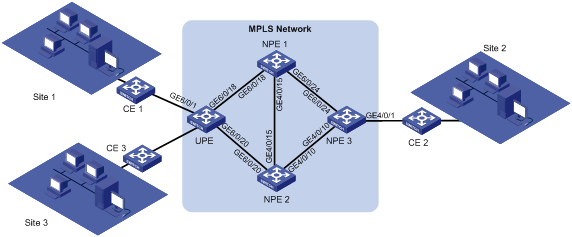
As shown in Figure 3, a customer has three sites connected to different CEs.
Configure H-VPLS with LSP access so that the three sites can communicate in VLAN 1000 over the MPLS backbone, and configure PW redundancy to improve link availability.
|
Device |
Interface |
IP address |
Device |
Interface |
IP address |
|
UPE |
Loopback0 |
192.0.0.4/32 |
NPE1 |
Loopback0 |
192.0.0.1/32 |
|
|
GE6/0/18 (VLAN 14) |
192.14.0.4/24 |
|
GE6/0/18 (VLAN 14) |
192.14.0.1/24 |
|
|
GE6/0/20 (VLAN 24) |
192.24.0.4/24 |
|
GE6/0/15 (VLAN 12) |
192.12.0.1/24 |
|
|
GE6/0/1 (VLAN 1000) |
|
|
GE6/0/24 (VLAN 13) |
192.13.0.1/24 |
|
NPE2 |
Loopback0 |
192.0.0.2/32 |
NPE3 |
Loopback0 |
192.0.0.3/32 |
|
|
GE4/0/20 (VLAN 24) |
192.24.0.2/24 |
|
GE4/0/24 (VLAN 13) |
192.13.0.3/24 |
|
|
GE4/0/15 (VLAN 12) |
192.12.0.2/24 |
|
GE4/0/10 (VLAN 23) |
192.23.0.3/24 |
|
|
GE4/0/10 (VLAN 23) |
192.23.0.2/24 |
|
GE4/0/1 (VLAN 1000) |
|
Requirements analysis
To establish public LSPs between PEs, enable MPLS and LDP on all PE and P devices.
To transmit private labels between PEs, create VPLS instances and specify LDP peers on the NPEs and UPE, and bind the VPLS instance to the receiving interface and VLAN on the UPE.
To differentiate private data, configure match criteria on the PEs' interfaces connected to CEs. In this example, configure a match criterion to permit packets with VLAN ID 1000 so that the customer sites can communicate within VLAN 1000 over the MPLS backbone.
To improve link availability, configure the UPE to establish a primary PW to NPE 1 and a backup PW to NPE 2. When the primary PW fails, the backup PW is used to forward VPN traffic.
Software version used
This configuration example was created and verified on S12500-CMW520-R1825P01.
Configuration procedures
This example only shows the H-VPLS with LSP access configuration between Site 1 and Site 2. Follow the same steps to configure H-VPLS with LSP access between different sites.
Configuring NPE 1
1. Configure interfaces and assign IP addresses:
# Configure the interface connected to NPE 2.
<Sysname> system-view
[Sysname] sysname NPE1
[NPE1] vlan 12
[NPE1-vlan12] port GigabitEthernet 6/0/15
[NPE1-vlan12] quit
[NPE1] interface vlan-interface 12
[NPE1-Vlan-interface12] ip address 192.12.0.1 24
[NPE1-Vlan-interface12] undo shutdown
[NPE1-Vlan-interface12] quit
[NPE1] interface GigabitEthernet 6/0/15
[NPE1-GigabitEthernet6/0/15] undo shutdown
[NPE1-GigabitEthernet6/0/15] quit
# Configure the interface connected to NPE 3.
[NPE1] vlan 13
[NPE1-vlan13] port GigabitEthernet 6/0/24
[NPE1-vlan13] quit
[NPE1] interface vlan-interface 13
[NPE1-Vlan-interface13] ip address 192.13.0.1 24
[NPE1-Vlan-interface13] undo shutdown
[NPE1-Vlan-interface13] quit
[NPE1] interface GigabitEthernet 6/0/24
[NPE1-GigabitEthernet6/0/24] undo shutdown
[NPE1-GigabitEthernet6/0/24] quit
# Configure the interface connected to UPE.
[NPE1] vlan 14
[NPE1-vlan14] port GigabitEthernet 6/0/18
[NPE1-vlan14] quit
[NPE1] interface vlan-interface 14
[NPE1-Vlan-interface14] ip address 192.14.0.1 24
[NPE1-Vlan-interface14] undo shutdown
[NPE1-Vlan-interface14] quit
[NPE1] interface GigabitEthernet 6/0/18
[NPE1-GigabitEthernet6/0/18] undo shutdown
[NPE1-GigabitEthernet6/0/18] quit
# Configure the loopback interface of NPE 1.
[NPE1] interface LoopBack 0
[NPE1-LoopBack0] ip address 192.0.0.1 32
[NPE1-LoopBack0] quit
2. Configure the IGP protocol:
# Configure the router ID.
[NPE1] router id 192.0.0.1
# Configure OSPF to advertise routes.
[NPE1] ospf 1
[NPE1-ospf-1] area 0
[NPE1-ospf-1-area-0.0.0.0] network 192.12.0.0 0.0.0.255
[NPE1-ospf-1-area-0.0.0.0] network 192.13.0.0 0.0.0.255
[NPE1-ospf-1-area-0.0.0.0] network 192.14.0.0 0.0.0.255
[NPE1-ospf-1-area-0.0.0.0] network 192.0.0.1 0.0.0.0
[NPE1-ospf-1-area-0.0.0.0] quit
[NPE1-ospf-1] quit
3. Configure basic MPLS:
# Configure the MPLS LSR ID, and enable MPLS, MPLS LDP, and MPLS L2VPN globally.
[NPE1] mpls lsr-id 192.0.0.1
[NPE1] mpls
[NPE1-mpls] quit
[NPE1] mpls ldp
[NPE1-mpls-ldp] quit
[NPE1] mpls l2vpn
# Enable MPLS and MPLS LDP on the VLAN interfaces.
[NPE1] interface vlan-interface 12
[NPE1-Vlan-interface12] mpls
[NPE1-Vlan-interface12] mpls ldp
[NPE1-Vlan-interface12] quit
[NPE1] interface vlan-interface 13
[NPE1-Vlan-interface13] mpls
[NPE1-Vlan-interface13] mpls ldp
[NPE1-Vlan-interface13] quit
[NPE1] interface vlan-interface 14
[NPE1-Vlan-interface14] mpls
[NPE1-Vlan-interface14] mpls ldp
[NPE1-Vlan-interface14] quit
# Configure the remote MPLS LDP sessions.
[NPE1] mpls ldp remote-peer 1
[NPE1-mpls-ldp-remote-1] remote-ip 192.0.0.4
[NPE1-mpls-ldp-remote-1] quit
[NPE1] mpls ldp remote-peer 2
[NPE1-mpls-ldp-remote-2] remote-ip 192.0.0.2
[NPE1-mpls-ldp-remote-2] quit
[NPE1] mpls ldp remote-peer 3
[NPE1-mpls-ldp-remote-3] remote-ip 192.0.0.3
[NPE1-mpls-ldp-remote-3] quit
4. Configure VPLS:
# Configure LDP VPLS instance vpn1000.
[NPE1] vsi vpn1000 static
[NPE1-vsi-vpn1000] pwsignal ldp
[NPE1-vsi-vpn1000-ldp] vsi-id 1000
# Configure the NPWs to NPE 2 and NPE 3 and the UPW to the UPE.
[NPE1-vsi-vpn1000-ldp] peer 192.0.0.2
[NPE1-vsi-vpn1000-ldp] peer 192.0.0.3
[NPE1-vsi-vpn1000-ldp] peer 192.0.0.4 upe
[NPE1-vsi-vpn1000-ldp] quit
[NPE1-vsi-vpn1000] quit
Configuring NPE 2
1. Configure interfaces and assign IP addresses:
# Configure the interface connected to NPE 1.
<Sysname> system-view
[Sysname] sysname NPE2
[NPE2] vlan 12
[NPE2-vlan12] port GigabitEthernet 4/0/15
[NPE2-vlan12] quit
[NPE2] interface vlan-interface 12
[NPE2-Vlan-interface12] ip address 192.12.0.2 24
[NPE2-Vlan-interface12] undo shutdown
[NPE2-Vlan-interface12] quit
[NPE2] interface GigabitEthernet 4/0/15
[NPE2-GigabitEthernet4/0/15] undo shutdown
[NPE2-GigabitEthernet4/0/15] quit
# Configure the interface connected to NPE 3.
[NPE2] vlan 23
[NPE2-vlan23] port GigabitEthernet 4/0/10
[NPE2-vlan23] quit
[NPE2] interface vlan-interface 23
[NPE2-Vlan-interface23] ip address 192.23.0.2 24
[NPE2-Vlan-interface23] undo shutdown
[NPE2-Vlan-interface23] quit
[NPE2] interface GigabitEthernet 4/0/10
[NPE2-GigabitEthernet4/0/10] undo shutdown
[NPE2-GigabitEthernet4/0/10] quit
# Configure the interface connected to UPE.
[NPE2] vlan 24
[NPE2-vlan24] port GigabitEthernet 4/0/20
[NPE2-vlan24] quit
[NPE2] interface vlan-interface 24
[NPE2-Vlan-interface24] ip address 192.24.0.2 24
[NPE2-Vlan-interface24] undo shutdown
[NPE2-Vlan-interface24] quit
[NPE2] interface GigabitEthernet 4/0/20
[NPE2-GigabitEthernet4/0/20] undo shutdown
[NPE2-GigabitEthernet4/0/20] quit
# Configure the loopback interface of NPE 2.
[NPE2] interface LoopBack 0
[NPE2-LoopBack0] ip address 192.0.0.2 32
[NPE2-LoopBack0] quit
2. Configure the IGP protocol:
# Configure the router ID.
[NPE2] router id 192.0.0.2
# Configure OSPF to advertise routes.
[NPE2] ospf 1
[NPE2-ospf-1] area 0
[NPE2-ospf-1-area-0.0.0.0] network 192.12.0.0 0.0.0.255
[NPE2-ospf-1-area-0.0.0.0] network 192.23.0.0 0.0.0.255
[NPE2-ospf-1-area-0.0.0.0] network 192.24.0.0 0.0.0.255
[NPE2-ospf-1-area-0.0.0.0] network 192.0.0.2 0.0.0.0
[NPE2-ospf-1-area-0.0.0.0] quit
[NPE2-ospf-1] quit
3. Configure basic MPLS:
# Configure the MPLS LSR ID, and enable MPLS, MPLS LDP, and MPLS L2VPN globally.
[NPE2] mpls lsr-id 192.0.0.2
[NPE2] mpls
[NPE2-mpls] quit
[NPE2] mpls ldp
[NPE2-mpls-ldp] quit
[NPE2] mpls l2vpn
# Enable MPLS and MPLS LDP on the VLAN interfaces.
[NPE2] interface vlan-interface 12
[NPE2-Vlan-interface12] mpls
[NPE2-Vlan-interface12] mpls ldp
[NPE2-Vlan-interface12] quit
[NPE2] interface vlan-interface 23
[NPE2-Vlan-interface23] mpls
[NPE2-Vlan-interface23] mpls ldp
[NPE2-Vlan-interface23] quit
[NPE2] interface vlan-interface 24
[NPE2-Vlan-interface24] mpls
[NPE2-Vlan-interface24] mpls ldp
[NPE2-Vlan-interface24] quit
# Configure the remote MPLS LDP sessions.
[NPE2] mpls ldp remote-peer 1
[NPE2-mpls-ldp-remote-1] remote-ip 192.0.0.4
[NPE2-mpls-ldp-remote-1] quit
[NPE2] mpls ldp remote-peer 2
[NPE2-mpls-ldp-remote-2] remote-ip 192.0.0.1
[NPE2-mpls-ldp-remote-2] quit
[NPE2] mpls ldp remote-peer 3
[NPE2-mpls-ldp-remote-3] remote-ip 192.0.0.3
[NPE2-mpls-ldp-remote-3] quit
4. Configure VPLS:
# Configure LDP VPLS instance vpn1000.
[NPE2] vsi vpn1000 static
[NPE2-vsi-vpn1000] pwsignal ldp
[NPE2-vsi-vpn1000-ldp] vsi-id 1000
# Configure the NPWs to NPE 1 and NPE 3 and the UPW to the UPE.
[NPE2-vsi-vpn1000-ldp] peer 192.0.0.1
[NPE2-vsi-vpn1000-ldp] peer 192.0.0.3
[NPE2-vsi-vpn1000-ldp] peer 192.0.0.4 upe
[NPE2-vsi-vpn1000-ldp] quit
[NPE2-vsi-vpn1000] quit
Configuring NPE 3
1. Configure interfaces and assign IP addresses.
# Configure the interface connected to NPE 1.
<Sysname> system-view
[Sysname] sysname NPE3
[NPE3] vlan 13
[NPE3-vlan13] port GigabitEthernet 4/0/24
[NPE3-vlan13] quit
[NPE3] interface vlan-interface 13
[NPE3-Vlan-interface13] ip address 192.13.0.3 24
[NPE3-Vlan-interface13] quit
# Configure the interface connected to NPE 2.
[NPE3] vlan 23
[NPE3-vlan23] port GigabitEthernet 4/0/10
[NPE3-vlan23] quit
[NPE3] interface vlan-interface 23
[NPE3-Vlan-interface23] ip address 192.23.0.3 24
[NPE3-Vlan-interface23] quit
# Configure the loopback interface of NPE 3.
[NPE3] interface LoopBack 0
[NPE3-LoopBack0] ip address 192.0.0.3 32
[NPE3-LoopBack0] quit
2. Configure the IGP protocol:
# Configure the router ID.
[NPE3] router id 192.0.0.3
# Configure OSPF to advertise routes.
[NPE3] ospf 1
[NPE3-ospf-1] area 0
[NPE3-ospf-1-area-0.0.0.0] network 192.13.0.0 0.0.0.255
[NPE3-ospf-1-area-0.0.0.0] network 192.23.0.0 0.0.0.255
[NPE3-ospf-1-area-0.0.0.0] network 192.0.0.3 0.0.0.0
[NPE3-ospf-1-area-0.0.0.0] quit
[NPE3-ospf-1] quit
3. Configure basic MPLS:
# Configure the MPLS LSR ID, and enable MPLS, MPLS LDP, and MPLS L2VPN globally.
[NPE3] mpls lsr-id 192.0.0.3
[NPE3] mpls
[NPE3-mpls] quit
[NPE3] mpls ldp
[NPE3-mpls-ldp] quit
[NPE3] mpls l2vpn
# Enable MPLS and MPLS LDP on the VLAN interfaces.
[NPE3] interface vlan-interface 13
[NPE3-Vlan-interface13] mpls
[NPE3-Vlan-interface13] mpls ldp
[NPE3-Vlan-interface13] quit
[NPE3] interface vlan-interface 23
[NPE3-Vlan-interface23] mpls
[NPE3-Vlan-interface23] mpls ldp
[NPE3-Vlan-interface23] quit
# Configure the remote MPLS LDP sessions.
[NPE3] mpls ldp remote-peer 1
[NPE3-mpls-ldp-remote-1] remote-ip 192.0.0.1
[NPE3-mpls-ldp-remote-1] quit
[NPE3] mpls ldp remote-peer 2
[NPE3-mpls-ldp-remote-2] remote-ip 192.0.0.2
[NPE3-mpls-ldp-remote-2] quit
4. Configure VPLS:
# Configure LDP VPLS instance vpn1000.
[NPE3] vsi vpn1000 static
[NPE3-vsi-vpn1000] pwsignal ldp
[NPE3-vsi-vpn1000-ldp] vsi-id 1000
# Configure the NPWs to NPE 1 and NPE 2.
[NPE3-vsi-vpn1000-ldp] peer 192.0.0.1
[NPE3-vsi-vpn1000-ldp] peer 192.0.0.2
[NPE3-vsi-vpn1000-ldp] quit
[NPE3-vsi-vpn1000] quit
# Bind the VPLS instance to the AC.
[NPE3] vlan 1000
[NPE3] interface GigabitEthernet 4/0/1
[NPE3-GigabitEthernet4/0/1] port link-type trunk
[NPE3-GigabitEthernet4/0/1] port trunk permit vlan 1000
Please wait... Done.
[NPE3-GigabitEthernet4/0/1] service-instance 1000
[NPE3-GigabitEthernet4/0/1-srv1000] encapsulation vlan 1000
[NPE3-GigabitEthernet4/0/1-srv1000] xconnect vsi vpn1000
[NPE3-GigabitEthernet4/0/1-srv1000] quit
[NPE3-GigabitEthernet4/0/1] quit
Configuring UPE
1. Configure interfaces and assign IP addresses:
# Configure the interface connected to NPE 1.
<Sysname> system-view
[Sysname] sysname UPE
[UPE] vlan 14
[UPE-vlan14] port GigabitEthernet 6/0/18
[UPE-vlan14] quit
[UPE] interface vlan-interface 14
[UPE-Vlan-interface14] ip address 192.14.0.4 24
[UPE-Vlan-interface14] undo shutdown
[UPE-Vlan-interface14] quit
[UPE] interface GigabitEthernet 6/0/18
[UPE-GigabitEthernet6/0/18] undo shutdown
[UPE-GigabitEthernet6/0/18] quit
# Configure the interface connected to NPE 2.
[UPE] vlan 24
[UPE-vlan24] port GigabitEthernet 6/0/20
[UPE-vlan24] quit
[UPE] interface vlan-interface 24
[UPE-Vlan-interface24] ip address 192.24.0.4 24
[UPE-Vlan-interface24] undo shutdown
[UPE-Vlan-interface24] quit
[UPE] interface GigabitEthernet 6/0/20
[UPE-GigabitEthernet6/0/20] undo shutdown
[UPE-GigabitEthernet6/0/20] quit
# Configure the loopback interface of UPE.
[UPE] interface LoopBack 0
[UPE-LoopBack0] ip address 192.0.0.4 32
[UPE-LoopBack0] quit
2. Configure the IGP protocol:
# Configure the router ID.
[UPE] router id 192.0.0.4
# Configure OSPF to advertise routes.
[UPE] ospf 1
[UPE-ospf-1] area 0
[UPE-ospf-1-area-0.0.0.0] network 192.14.0.0 0.0.0.255
[UPE-ospf-1-area-0.0.0.0] network 192.24.0.0 0.0.0.255
[UPE-ospf-1-area-0.0.0.0] network 192.0.0.4 0.0.0.0
[UPE-ospf-1-area-0.0.0.0] quit
[UPE-ospf-1] quit
3. Configure basic MPLS:
# Configure the MPLS LSR ID, and enable MPLS, MPLS LDP, and MPLS L2VPN globally.
[UPE] mpls lsr-id 192.0.0.4
[UPE] mpls
[UPE-mpls] quit
[UPE] mpls ldp
[UPE-mpls-ldp] quit
[UPE] mpls l2vpn
# Enable MPLS and MPLS LDP on the VLAN interfaces.
[UPE] interface vlan-interface 14
[UPE-Vlan-interface14] mpls
[UPE-Vlan-interface14] mpls ldp
[UPE-Vlan-interface14] quit
[UPE] interface vlan-interface 24
[UPE-Vlan-interface24] mpls
[UPE-Vlan-interface24] mpls ldp
[UPE-Vlan-interface24] quit
# Configure the remote MPLS LDP sessions.
[UPE] mpls ldp remote-peer 1
[UPE-mpls-ldp-remote-1] remote-ip 192.0.0.1
[UPE-mpls-ldp-remote-1] quit
[UPE] mpls ldp remote-peer 2
[UPE-mpls-ldp-remote-2] remote-ip 192.0.0.2
[UPE-mpls-ldp-remote-2] quit
4. Configure VPLS:
# Configure LDP VPLS instance vpn1000.
[UPE] vsi vpn1000 static
[UPE-vsi-vpn1000] pwsignal ldp
[UPE-vsi-vpn1000-ldp] vsi-id 1000
# Configure the primary PW to NPE 1 and the backup PW to NPE 2.
[UPE-vsi-vpn1000-ldp] peer 192.0.0.1 backup-peer 192.0.0.2 dual-npe revertive wtr-time 1
[UPE-vsi-vpn1000-ldp] quit
[UPE-vsi-vpn1000] quit
# Bind the VPLS instance to the AC.
[UPE] vlan 1000
[UPE] interface GigabitEthernet 6/0/1
[UPE-GigabitEthernet6/0/1] port link-type trunk
[UPE-GigabitEthernet6/0/1] port trunk permit vlan 1000
Please wait... Done.
[UPE-GigabitEthernet6/0/1] service-instance 1000
[UPE-GigabitEthernet6/0/1] undo shutdown
[UPE-GigabitEthernet6/0/1-srv1000] encapsulation s-vid 1000
[UPE-GigabitEthernet6/0/1-srv1000] xconnect vsi vpn1000
[UPE-GigabitEthernet6/0/1-srv1000] quit
[UPE-GigabitEthernet6/0/1] quit
Verifying the configuration
Use display commands to verify the following:
· VPLS PWs are established between NPE 1, NPE 2, and NPE 3.
· The primary PW is established between UPE and NPE 1, and the backup PW is established between UPE and NPE 2.
# View PWs on UPE.
[UPE] display vpls connection vsi vpn1000
Total 2 connection(s),
connections: 1 up, 1 block, 0 down
VSI Name: vpn1000 Signaling: ldp
VsiID VsiType PeerAddr InLabel OutLabel LinkID VCState
1000 vlan 192.0.0.1 131072 131074 1 up
1000 vlan 192.0.0.2 131073 131074 2 block
# View PWs on NPE 1.
[NPE1] display vpls connection vsi vpn1000
Total 3 connection(s),
connections: 3 up, 0 block, 0 down
VSI Name: vpn1000 Signaling: ldp
VsiID VsiType PeerAddr InLabel OutLabel LinkID VCState
1000 vlan 192.0.0.2 131072 131072 1 up
1000 vlan 192.0.0.3 131073 131072 2 up
1000 vlan 192.0.0.4 131074 131072 3 up
# View PWs on NPE 2.
[NPE2] display vpls connection vsi vpn1000
Total 3 connection(s),
connections: 3 up, 0 block, 0 down
VSI Name: vpn1000 Signaling: ldp
VsiID VsiType PeerAddr InLabel OutLabel LinkID VCState
1000 vlan 192.0.0.1 131072 131072 1 up
1000 vlan 192.0.0.3 131073 131073 2 up
1000 vlan 192.0.0.4 131074 131073 3 up
# View PWs on NPE 3.
[NPE3] display vpls connection vsi vpn1000
Total 2 connection(s),
connections: 2 up, 0 block, 0 down
VSI Name: vpn1000 Signaling: ldp
VsiID VsiType PeerAddr InLabel OutLabel LinkID VCState
1000 vlan 192.0.0.1 131072 131073 1 up
1000 vlan 192.0.0.2 131073 131073 2 up
Configuration files
· NPE 1:
[NPE1] display current-configuration
#
sysname NPE1
#
domain default enable system
#
router id 192.0.0.1
#
xbar load-balance
#
forward-path check enable
#
mpls lsr-id 192.0.0.1
#
vlan 1
#
vlan 12
#
vlan 13
#
vlan 14
#
mpls
#
mpls l2vpn
#
mpls ldp
#
mpls ldp remote-peer 1
remote-ip 192.0.0.4
#
mpls ldp remote-peer 2
remote-ip 192.0.0.2
#
mpls ldp remote-peer 3
remote-ip 192.0.0.3
#
vsi vpn1000 static
pwsignal ldp
vsi-id 1000
peer 192.0.0.2
peer 192.0.0.3
peer 192.0.0.4 upe
#
interface LoopBack0
ip address 192.0.0.1 255.255.255.255
#
interface Vlan-interface12
ip address 192.12.0.1 255.255.255.0
mpls
mpls ldp
#
interface Vlan-interface13
ip address 192.13.0.1 255.255.255.0
mpls
mpls ldp
#
interface Vlan-interface14
ip address 192.14.0.1 255.255.255.0
mpls
mpls ldp
#
interface GigabitEthernet6/0/15
port link-mode bridge
port access vlan 12
#
interface GigabitEthernet6/0/18
port link-mode bridge
port access vlan 14
#
interface GigabitEthernet6/0/24
port link-mode bridge
port access vlan 13
#
ospf 1
area 0.0.0.0
network 192.12.0.0 0.0.0.255
network 192.13.0.0 0.0.0.255
network 192.14.0.0 0.0.0.255
network 192.0.0.1 0.0.0.0
#
· NPE 2:
[NPE2] display current-configuration
#
sysname NPE2
#
domain default enable system
#
router id 192.0.0.2
#
xbar load-balance
#
forward-path check enable
#
mpls lsr-id 192.0.0.2
#
vlan 1
#
vlan 12
#
vlan 23
#
vlan 24
#
mpls
#
mpls l2vpn
#
mpls ldp
#
mpls ldp remote-peer 1
remote-ip 192.0.0.4
#
mpls ldp remote-peer 2
remote-ip 192.0.0.1
#
mpls ldp remote-peer 3
remote-ip 192.0.0.3
#
vsi vpn1000 static
pwsignal ldp
vsi-id 1000
peer 192.0.0.1
peer 192.0.0.3
peer 192.0.0.4 upe
#
interface LoopBack0
ip address 192.0.0.2 255.255.255.255
#
interface Vlan-interface12
ip address 192.12.0.2 255.255.255.0
mpls
mpls ldp
#
interface Vlan-interface23
ip address 192.23.0.2 255.255.255.0
mpls
mpls ldp
#
interface Vlan-interface24
ip address 192.24.0.2 255.255.255.0
mpls
mpls ldp
#
interface GigabitEthernet4/0/10
port link-mode bridge
port access vlan 23
#
interface GigabitEthernet4/0/15
port link-mode bridge
port access vlan 12
#
interface GigabitEthernet4/0/20
port link-mode bridge
port access vlan 24
#
ospf 1
area 0.0.0.0
network 192.12.0.0 0.0.0.255
network 192.23.0.0 0.0.0.255
network 192.24.0.0 0.0.0.255
network 192.0.0.2 0.0.0.0
#
· NPE 3:
[NPE3] display current-configuration
#
sysname NPE3
#
domain default enable system
#
router id 192.0.0.3
#
xbar load-balance
#
forward-path check enable
#
mpls lsr-id 192.0.0.3
#
vlan 1
#
vlan 13
#
vlan 23
#
vlan 1000
#
mpls
#
mpls l2vpn
#
mpls ldp
#
mpls ldp remote-peer 1
remote-ip 192.0.0.1
#
mpls ldp remote-peer 2
remote-ip 192.0.0.2
#
vsi vpn1000 static
pwsignal ldp
vsi-id 1000
peer 192.0.0.1
peer 192.0.0.2
#
interface LoopBack0
ip address 192.0.0.3 255.255.255.255
#
interface Vlan-interface13
ip address 192.13.0.3 255.255.255.0
mpls
mpls ldp
#
interface Vlan-interface23
ip address 192.23.0.3 255.255.255.0
mpls
mpls ldp
#
interface GigabitEthernet4/0/1
port link-mode bridge
port link-type trunk
port trunk permit vlan 1 1000
service-instance 1000
encapsulation s-vid 1000
xconnect vsi vpn1000
#
interface GigabitEthernet4/0/10
port link-mode bridge
port access vlan 23
#
interface GigabitEthernet4/0/24
port link-mode bridge
port access vlan 13
#
ospf 1
area 0.0.0.0
network 192.13.0.0 0.0.0.255
network 192.23.0.0 0.0.0.255
network 192.0.0.3 0.0.0.0
#
· UPE:
[UPE] display current-configuration
#
sysname UPE
#
domain default enable system
#
router id 192.0.0.4
#
xbar load-balance
#
forward-path check enable
#
mpls lsr-id 192.0.0.4
#
vlan 1
#
vlan 14
#
vlan 24
#
vlan 1000
#
mpls
#
mpls l2vpn
#
mpls ldp
#
mpls ldp remote-peer 1
remote-ip 192.0.0.1
#
mpls ldp remote-peer 2
remote-ip 192.0.0.2
#
vsi vpn1000 static
pwsignal ldp
vsi-id 1000
peer 192.0.0.1 backup-peer 192.0.0.2 dual-npe revertive wtr-time 1
#
interface LoopBack0
ip address 192.0.0.4 255.255.255.255
#
interface Vlan-interface14
ip address 192.14.0.4 255.255.255.0
mpls
mpls ldp
#
interface Vlan-interface24
ip address 192.24.0.4 255.255.255.0
mpls
mpls ldp
#
interface GigabitEthernet6/0/1
port link-mode bridge
port link-type trunk
port trunk permit vlan 1 1000
service-instance 1000
encapsulation s-vid 1000
xconnect vsi vpn1000
#
interface GigabitEthernet6/0/18
port link-mode bridge
port access vlan 14
#
interface GigabitEthernet6/0/20
port link-mode bridge
port access vlan 24
#
ospf 1
area 0.0.0.0
network 192.14.0.0 0.0.0.255
network 192.24.0.0 0.0.0.255
network 192.0.0.4 0.0.0.0
#
Example: Configuring BFD for H-VPLS
Network requirements
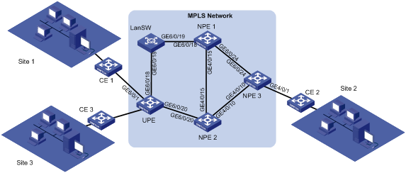
As shown in Figure 4, a customer has three sites connected to different CEs, and often uses voice or video services.
Configure H-VPLS so that the three sites can communicate in VLAN 1000 over the MPLS backbone, and configure BFD for H-VPLS to ensure fast link failover.
|
Device |
Interface |
IP address |
Device |
Interface |
IP address |
|
UPE |
Loopback0 |
192.0.0.4/32 |
NPE1 |
Loopback0 |
192.0.0.1/32 |
|
|
GE6/0/18 (VLAN 14) |
192.14.0.4/24 |
|
GE6/0/18 (VLAN 14) |
192.14.0.1/24 |
|
|
GE6/0/20 (VLAN 24) |
192.24.0.4/24 |
|
GE6/0/15 (VLAN 12) |
192.12.0.1/24 |
|
|
GE6/0/1 (VLAN 1000) |
|
|
GE6/0/24 (VLAN 13) |
192.13.0.1/24 |
|
NPE2 |
Loopback0 |
192.0.0.2/32 |
NPE3 |
Loopback0 |
192.0.0.3/32 |
|
|
GE4/0/20 (VLAN 24) |
192.24.0.2/24 |
|
GE4/0/24 (VLAN 13) |
192.13.0.3/24 |
|
|
GE4/0/15 (VLAN 12) |
192.12.0.2/24 |
|
GE4/0/10 (VLAN 23) |
192.23.0.3/24 |
|
|
GE4/0/10 (VLAN 23) |
192.23.0.2/24 |
|
GE4/0/1 (VLAN 1000) |
|
Requirements analysis
To establish public LSPs between PEs, enable MPLS and LDP on all PE and P devices.
To transmit private labels between PEs, create VPLS instances and specify LDP peers on the NPEs and UPE, and bind the VPLS instance to the receiving interface and VLAN on the UPE.
To differentiate private data, configure match criteria on the PEs' interfaces connected to CEs. In this example, configure a match criterion to permit packets with VLAN ID 1000 so that the customer sites can communicate within VLAN 1000 over the MPLS backbone.
To ensure high link availability for voice and video services, configure the UPE to establish a primary PW to NPE 1 and a backup PW to NPE 2, and configure BFD on the primary PW. When the primary PW fails, VPN traffic can be quickly switched to the backup PW.
Software version used
This configuration example was created and verified on S12500-CMW520-R1825P01.
Configuration procedures
This example only shows the H-VPLS configuration between Site 1 and Site 2. Follow the same steps to configure H-VPLS between different sites.
Configuring LanSW
# Configure the VLAN and add the ports to the VLAN.
<Sysname> system-view
[Sysname] sysname LanSW
[LanSW] vlan 14
[LanSW-vlan14] port GigabitEthernet 6/0/18
[LanSW-vlan14] port GigabitEthernet 6/0/19
[LanSW] interface GigabitEthernet 6/0/18
[LanSW-GigabitEthernet6/0/18] undo shutdown
[LanSW-GigabitEthernet6/0/18] quit
[LanSW] interface GigabitEthernet 6/0/19
[LanSW-GigabitEthernet6/0/19] undo shutdown
[LanSW-GigabitEthernet6/0/19] quit
Configuring NPE 1
1. Configure interfaces and assign IP addresses:
# Configure the interface connected to NPE 2.
<Sysname> system-view
[Sysname] sysname NPE1
[NPE1] vlan 12
[NPE1-vlan12] port GigabitEthernet 6/0/15
[NPE1-vlan12] quit
[NPE1] interface vlan-interface 12
[NPE1-Vlan-interface12] ip address 192.12.0.1 24
[NPE1-Vlan-interface12] undo shutdown
[NPE1-Vlan-interface12] quit
[NPE1] interface GigabitEthernet 6/0/15
[NPE1-GigabitEthernet6/0/15] undo shutdown
[NPE1-GigabitEthernet6/0/15] quit
# Configure the interface connected to NPE 3.
[NPE1] vlan 13
[NPE1-vlan13] port GigabitEthernet 6/0/24
[NPE1-vlan13] quit
[NPE1] interface vlan-interface 13
[NPE1-Vlan-interface13] ip address 192.13.0.1 24
[NPE1-Vlan-interface13] undo shutdown
[NPE1-Vlan-interface13] quit
[NPE1] interface GigabitEthernet 6/0/24
[NPE1-GigabitEthernet6/0/24] undo shutdown
[NPE1-GigabitEthernet6/0/24] quit
# Configure the interface connected to UPE.
[NPE1] vlan 14
[NPE1-vlan14] port GigabitEthernet 6/0/18
[NPE1-vlan14] quit
[NPE1] interface vlan-interface 14
[NPE1-Vlan-interface14] ip address 192.14.0.1 24
[NPE1-Vlan-interface14] undo shutdown
[NPE1-Vlan-interface14] quit
[NPE1] interface GigabitEthernet 6/0/18
[NPE1-GigabitEthernet6/0/18] undo shutdown
[NPE1-GigabitEthernet6/0/18] quit
# Configure the loopback interface of NPE 1.
[NPE1] interface LoopBack 0
[NPE1-LoopBack0] ip address 192.0.0.1 32
[NPE1-LoopBack0] quit
2. Configure the IGP protocol:
# Configure the router ID.
[NPE1] router id 192.0.0.1
# Configure OSPF to advertise routes.
[NPE1] ospf 1
[NPE1-ospf-1] area 0
[NPE1-ospf-1-area-0.0.0.0] network 192.12.0.0 0.0.0.255
[NPE1-ospf-1-area-0.0.0.0] network 192.13.0.0 0.0.0.255
[NPE1-ospf-1-area-0.0.0.0] network 192.14.0.0 0.0.0.255
[NPE1-ospf-1-area-0.0.0.0] network 192.0.0.1 0.0.0.0
[NPE1-ospf-1-area-0.0.0.0] quit
[NPE1-ospf-1] quit
3. Configure basic MPLS:
# Configure the MPLS LSR ID, and enable MPLS, MPLS LDP, and MPLS L2VPN globally.
[NPE1] mpls lsr-id 192.0.0.1
[NPE1] mpls
[NPE1-mpls] quit
[NPE1] mpls ldp
[NPE1-mpls-ldp] quit
[NPE1] mpls l2vpn
# Enable MPLS and MPLS LDP on the VLAN interfaces.
[NPE1] interface vlan-interface 12
[NPE1-Vlan-interface12] mpls
[NPE1-Vlan-interface12] mpls ldp
[NPE1-Vlan-interface12] quit
[NPE1] interface vlan-interface 13
[NPE1-Vlan-interface13] mpls
[NPE1-Vlan-interface13] mpls ldp
[NPE1-Vlan-interface13] quit
[NPE1] interface vlan-interface 14
[NPE1-Vlan-interface14] mpls
[NPE1-Vlan-interface14] mpls ldp
[NPE1-Vlan-interface14] quit
4. Configure VPLS:
# Configure LDP VPLS instance vpn1000.
[NPE1] vsi vpn1000 static
[NPE1-vsi-vpn1000] pwsignal ldp
[NPE1-vsi-vpn1000-ldp] vsi-id 1000
# Configure the NPWs to NPE 2 and NPE 3 and the UPW to the UPE.
[NPE1-vsi-vpn1000-ldp] peer 192.0.0.2
[NPE1-vsi-vpn1000-ldp] peer 192.0.0.3
[NPE1-vsi-vpn1000-ldp] peer 192.0.0.4 upe
[NPE1-vsi-vpn1000-ldp] quit
[NPE1-vsi-vpn1000] quit
5. Enable BFD for the primary PW:
# Configure the remote MPLS LDP session.
[NPE1] mpls ldp remote-peer 1
[NPE1-mpls-ldp-remote-1] remote-ip 192.0.0.4
# Enable BFD for the session and specify the BFD detection interval as 30 ms.
[NPE1-mpls-ldp-remote-1] remote-ip bfd
[NPE1-mpls-ldp-remote-1] quit
[NPE1] interface LoopBack 0
[NPE1-LoopBack0] bfd min-transmit-interval 10
[NPE1-LoopBack0] bfd min-receive-interval 10
[NPE1-LoopBack0] bfd detect-multiplier 3
[NPE1-LoopBack0] quit
Configuring NPE 2
1. Configure interfaces and assign IP addresses.
# Configure the interface connected to NPE 1.
<Sysname> system-view
[Sysname] sysname NPE2
[NPE2] vlan 12
[NPE2-vlan12] port GigabitEthernet 4/0/15
[NPE2-vlan12] quit
[NPE2] interface vlan-interface 12
[NPE2-Vlan-interface12] ip address 192.12.0.2 24
[NPE2-Vlan-interface12] undo shutdown
[NPE2-Vlan-interface12] quit
[NPE2] interface GigabitEthernet 4/0/15
[NPE2-GigabitEthernet4/0/15] undo shutdown
[NPE2-GigabitEthernet4/0/15] quit
# Configure the interface connected to NPE 3.
[NPE2] vlan 23
[NPE2-vlan23] port GigabitEthernet 4/0/10
[NPE2-vlan23] quit
[NPE2] interface vlan-interface 23
[NPE2-Vlan-interface23] ip address 192.23.0.2 24
[NPE2-Vlan-interface23] undo shutdown
[NPE2-Vlan-interface23] quit
[NPE2] interface GigabitEthernet 4/0/10
[NPE2-GigabitEthernet4/0/10] undo shutdown
[NPE2-GigabitEthernet4/0/10] quit
# Configure the interface connected to UPE.
[NPE2] vlan 24
[NPE2-vlan24] port GigabitEthernet 4/0/20
[NPE2-vlan24] quit
[NPE2] interface vlan-interface 24
[NPE2-Vlan-interface24] ip address 192.24.0.2 24
[NPE2-Vlan-interface24] undo shutdown
[NPE2-Vlan-interface24] quit
[NPE2] interface GigabitEthernet 4/0/20
[NPE2-GigabitEthernet4/0/20] undo shutdown
[NPE2-GigabitEthernet4/0/20] quit
# Configure the loopback interface of NPE 2.
[NPE2] interface LoopBack 0
[NPE2-LoopBack0] ip address 192.0.0.2 32
[NPE2-LoopBack0] quit
2. Configure the IGP protocol:
# Configure the router ID.
[NPE2] router id 192.0.0.2
# Configure OSPF to advertise routes.
[NPE2] ospf 1
[NPE2-ospf-1] area 0
[NPE2-ospf-1-area-0.0.0.0] network 192.12.0.0 0.0.0.255
[NPE2-ospf-1-area-0.0.0.0] network 192.23.0.0 0.0.0.255
[NPE2-ospf-1-area-0.0.0.0] network 192.24.0.0 0.0.0.255
[NPE2-ospf-1-area-0.0.0.0] network 192.0.0.2 0.0.0.0
[NPE2-ospf-1-area-0.0.0.0] quit
[NPE2-ospf-1] quit
3. Configure basic MPLS:
# Configure the MPLS LSR ID, and enable MPLS, MPLS LDP, and MPLS L2VPN globally.
[NPE2] mpls lsr-id 192.0.0.2
[NPE2] mpls
[NPE2-mpls] quit
[NPE2] mpls ldp
[NPE2-mpls-ldp] quit
[NPE2] mpls l2vpn
# Enable MPLS and MPLS LDP on the VLAN interfaces.
[NPE2] interface vlan-interface 12
[NPE2-Vlan-interface12] mpls
[NPE2-Vlan-interface12] mpls ldp
[NPE2-Vlan-interface12] quit
[NPE2] interface vlan-interface 23
[NPE2-Vlan-interface23] mpls
[NPE2-Vlan-interface23] mpls ldp
[NPE2-Vlan-interface23] quit
[NPE2] interface vlan-interface 24
[NPE2-Vlan-interface24] mpls
[NPE2-Vlan-interface24] mpls ldp
[NPE2-Vlan-interface24] quit
4. Configure VPLS:
# Configure LDP VPLS instance vpn1000.
[NPE2] vsi vpn1000 static
[NPE2-vsi-vpn1000] pwsignal ldp
[NPE2-vsi-vpn1000-ldp] vsi-id 1000
# Configure the NPWs to NPE 1 and NPE 3 and the UPW to the UPE.
[NPE2-vsi-vpn1000-ldp] peer 192.0.0.1
[NPE2-vsi-vpn1000-ldp] peer 192.0.0.3
[NPE2-vsi-vpn1000-ldp] peer 192.0.0.4 upe
[NPE2-vsi-vpn1000-ldp] quit
[NPE2-vsi-vpn1000] quit
Configuring NPE 3
1. Configure interfaces and assign IP addresses:
# Configure the interface connected to NPE 1.
<Sysname> system-view
[Sysname] sysname NPE3
[NPE3] vlan 13
[NPE3-vlan13] port GigabitEthernet 4/0/24
[NPE3-vlan13] quit
[NPE3] interface vlan-interface 13
[NPE3-Vlan-interface13] ip address 192.13.0.3 24
[NPE3-Vlan-interface13] undo shutdown
[NPE3-Vlan-interface13] quit
[NPE3] interface GigabitEthernet 4/0/24
[NPE3-GigabitEthernet4/0/24] undo shutdown
[NPE3-GigabitEthernet4/0/24] quit
# Configure the interface connected to NPE 2.
[NPE3] vlan 23
[NPE3-vlan23] port GigabitEthernet 4/0/10
[NPE3-vlan23] quit
[NPE3] interface vlan-interface 23
[NPE3-Vlan-interface23] ip address 192.23.0.3 24
[NPE3-Vlan-interface23] undo shutdown
[NPE3-Vlan-interface23] quit
[NPE3] interface GigabitEthernet 4/0/10
[NPE3-GigabitEthernet4/0/10] undo shutdown
[NPE3-GigabitEthernet4/0/10] quit
# Configure the loopback interface of NPE 3.
[NPE3] interface LoopBack 0
[NPE3-LoopBack0] ip address 192.0.0.3 32
[NPE3-LoopBack0] quit
2. Configure the IGP protocol:
# Configure the router ID.
[NPE3] router id 192.0.0.3
# Configure OSPF to advertise routes.
[NPE3] ospf 1
[NPE3-ospf-1] area 0
[NPE3-ospf-1-area-0.0.0.0] network 192.13.0.0 0.0.0.255
[NPE3-ospf-1-area-0.0.0.0] network 192.23.0.0 0.0.0.255
[NPE3-ospf-1-area-0.0.0.0] network 192.0.0.3 0.0.0.0
[NPE3-ospf-1-area-0.0.0.0] quit
[NPE3-ospf-1] quit
3. Configure basic MPLS:
# Configure the MPLS LSR ID, and enable MPLS, MPLS LDP, and MPLS L2VPN globally.
[NPE3] mpls lsr-id 192.0.0.3
[NPE3] mpls
[NPE3-mpls] quit
[NPE3] mpls ldp
[NPE3-mpls-ldp] quit
[NPE3] mpls l2vpn
# Enable MPLS and MPLS LDP on the VLAN interfaces.
[NPE3] interface vlan-interface 13
[NPE3-Vlan-interface13] mpls
[NPE3-Vlan-interface13] mpls ldp
[NPE3-Vlan-interface13] quit
[NPE3] interface vlan-interface 23
[NPE3-Vlan-interface23] mpls
[NPE3-Vlan-interface23] mpls ldp
[NPE3-Vlan-interface23] quit
4. Configure VPLS:
# Configure LDP VPLS instance vpn1000.
[NPE3] vsi vpn1000 static
[NPE3-vsi-vpn1000] pwsignal ldp
[NPE3-vsi-vpn1000-ldp] vsi-id 1000
# Configure the NPWs to NPE 1 and NPE 2.
[NPE3-vsi-vpn1000-ldp] peer 192.0.0.1
[NPE3-vsi-vpn1000-ldp] peer 192.0.0.2
[NPE3-vsi-vpn1000-ldp] quit
[NPE3-vsi-vpn1000] quit
# Bind the VPLS instance to the AC.
[NPE3] vlan 1000
[NPE3] interface GigabitEthernet 4/0/1
[NPE3-GigabitEthernet4/0/1] port link-type trunk
[NPE3-GigabitEthernet4/0/1] port trunk permit vlan 1000
Please wait... Done.
[NPE3-GigabitEthernet4/0/1] service-instance 1000
[NPE3-GigabitEthernet4/0/1] undo shutdown
[NPE3-GigabitEthernet4/0/1-srv1000] encapsulation s-vid 1000
[NPE3-GigabitEthernet4/0/1-srv1000] xconnect vsi vpn1000
[NPE3-GigabitEthernet4/0/1-srv1000] quit
[NPE3-GigabitEthernet4/0/1] quit
Configuring UPE
1. Configure interfaces and assign IP addresses:
# Configure the interface connected to NPE 1.
<Sysname> system-view
[Sysname] sysname UPE
[UPE] vlan 14
[UPE-vlan14] port GigabitEthernet 6/0/18
[UPE-vlan14] quit
[UPE] interface vlan-interface 14
[UPE-Vlan-interface14] ip address 192.14.0.4 24
[UPE-Vlan-interface14] undo shutdown
[UPE-Vlan-interface14] quit
[UPE] interface GigabitEthernet 6/0/18
[UPE-GigabitEthernet6/0/18] undo shutdown
[UPE-GigabitEthernet6/0/18] quit
# Configure the interface connected to NPE 2.
[UPE] vlan 24
[UPE-vlan24] port GigabitEthernet 6/0/20
[UPE-vlan24] quit
[UPE] interface vlan-interface 24
[UPE-Vlan-interface24] ip address 192.24.0.4 24
[UPE-Vlan-interface24] undo shutdown
[UPE-Vlan-interface24] quit
[UPE] interface GigabitEthernet 6/0/20
[UPE-GigabitEthernet6/0/20] undo shutdown
[UPE-GigabitEthernet6/0/20] quit
# Configure the loopback interface of UPE.
[UPE] interface LoopBack 0
[UPE-LoopBack0] ip address 192.0.0.4 32
[UPE-LoopBack0] quit
2. Configure the IGP protocol:
# Configure the router ID.
[UPE] router id 192.0.0.4
# Configure OSPF to advertise routes.
[UPE] ospf 1
[UPE-ospf-1] area 0
[UPE-ospf-1-area-0.0.0.0] network 192.14.0.0 0.0.0.255
[UPE-ospf-1-area-0.0.0.0] network 192.24.0.0 0.0.0.255
[UPE-ospf-1-area-0.0.0.0] network 192.0.0.4 0.0.0.0
[UPE-ospf-1-area-0.0.0.0] quit
[UPE-ospf-1] quit
3. Configure basic MPLS:
# Configure the MPLS LSR ID, and enable MPLS, MPLS LDP, and MPLS L2VPN globally.
[UPE] mpls lsr-id 192.0.0.4
[UPE] mpls
[UPE-mpls] quit
[UPE] mpls ldp
[UPE-mpls-ldp] quit
[UPE] mpls l2vpn
# Enable MPLS and MPLS LDP on the VLAN interfaces.
[UPE] interface vlan-interface 14
[UPE-Vlan-interface14] mpls
[UPE-Vlan-interface14] mpls ldp
[UPE-Vlan-interface14] quit
[UPE] interface vlan-interface 24
[UPE-Vlan-interface24] mpls
[UPE-Vlan-interface24] mpls ldp
[UPE-Vlan-interface24] quit
4. Configure VPLS:
# Configure LDP VPLS instance vpn1000.
[UPE] vsi vpn1000 static
[UPE-vsi-vpn1000] pwsignal ldp
[UPE-vsi-vpn1000-ldp] vsi-id 1000
# Configure the primary PW to NPE 1 and the backup PW NPE 2.
[UPE-vsi-vpn1000-ldp] peer 192.0.0.1 backup-peer 192.0.0.2 dual-npe revertive wtr-time 1
[UPE-vsi-vpn1000-ldp] quit
[UPE-vsi-vpn1000] quit
# Bind the VPLS instance to the AC.
[UPE] vlan 1000
[UPE] interface gigabitEthernet 6/0/1
[UPE-GigabitEthernet6/0/1] port link-type trunk
[UPE-GigabitEthernet6/0/1] port trunk permit vlan 1000
Please wait... Done.
[UPE-GigabitEthernet6/0/1] service-instance 1000
[UPE-GigabitEthernet6/0/1] undo shutdown
[UPE-GigabitEthernet6/0/1-srv1000] encapsulation s-vid 1000
[UPE-GigabitEthernet6/0/1-srv1000] xconnect vsi vpn1000
[UPE-GigabitEthernet6/0/1-srv1000] quit
[UPE-GigabitEthernet6/0/1] quit
5. Configure BFD for the primary PW:
# Configure the remote MPLS LDP session.
[UPE] mpls ldp remote-peer 1
[UPE-mpls-ldp-remote-1] remote-ip 192.0.0.1
# Enable BFD for the session and specify the BFD detection interval as 30 ms.
[UPE-mpls-ldp-remote-1] remote-ip bfd
[UPE-mpls-ldp-remote-1] quit
[UPE] interface LoopBack 0
[UPE-LoopBack0] bfd min-transmit-interval 10
[UPE-LoopBack0] bfd min-receive-interval 10
[UPE-LoopBack0] bfd detect-multiplier 3
[UPE-LoopBack0] quit
Verifying the configuration
Use display commands to verify the following:
· VPLS PWs are established between NPE 1, NPE 2, and NPE 3.
· The primary PW is established between UPE and NPE 1, and the backup PW is established between UPE and NPE 2.
· BFD detects the primary PW for fast link failover.
# View PWs.
[UPE] display vpls connection vsi vpn1000
Total 2 connection(s),
connections: 1 up, 1 block, 0 down
VSI Name: vpn1000 Signaling: ldp
VsiID VsiType PeerAddr InLabel OutLabel LinkID VCState
1000 vlan 192.0.0.1 131072 131074 1 up
1000 vlan 192.0.0.2 131073 131074 2 block
# View the BFD session.
[UPE] display bfd session
Total session number: 1 Up session number: 1 Init mode: Active
IPv4 session working under Ctrl mode:
LD/RD SourceAddr DestAddr State Holdtime Interface
7/20 192.0.0.4 192.0.0.1 Up 30ms Loop0
Configuration files
· LanSW:
[LanSW] display current-configuration
#
sysname LanSW
#
domain default enable system
#
vlan 14
#
interface GigabitEthernet6/0/18
port link-mode bridge
port access vlan 14
#
interface GigabitEthernet6/0/19
port link-mode bridge
port access vlan 14
#
· NPE 1:
[NPE1] display current-configuration
#
sysname NPE1
#
domain default enable system
#
router id 192.0.0.1
#
xbar load-balance
#
forward-path check enable
#
mpls lsr-id 192.0.0.1
#
vlan 1
#
vlan 12
#
vlan 13
#
vlan 14
#
mpls
#
mpls l2vpn
#
mpls ldp
#
mpls ldp remote-peer 1
remote-ip 192.0.0.4
remote-ip bfd
#
domain system
access-limit disable
state active
idle-cut disable
self-service-url disable
#
user-group system
#
vsi vpn1000 static
pwsignal ldp
vsi-id 1000
peer 192.0.0.2
peer 192.0.0.3
peer 192.0.0.4 upe
#
interface NULL0
#
interface LoopBack0
ip address 192.0.0.1 255.255.255.255
bfd min-transmit-interval 10
bfd min-receive-interval 10
bfd detect-multiplier 3
#
interface Vlan-interface12
ip address 192.12.0.1 255.255.255.0
mpls
mpls ldp
#
interface Vlan-interface13
ip address 192.13.0.1 255.255.255.0
mpls
mpls ldp
#
interface Vlan-interface14
ip address 192.14.0.1 255.255.255.0
mpls
mpls ldp
#
interface GigabitEthernet6/0/15
port link-mode bridge
port access vlan 12
#
interface GigabitEthernet6/0/18
port link-mode bridge
port access vlan 14
#
interface GigabitEthernet6/0/24
port link-mode bridge
port access vlan 13
#
interface M-Ethernet0/0/0
#
ospf 1
area 0.0.0.0
network 192.12.0.0 0.0.0.255
network 192.13.0.0 0.0.0.255
network 192.14.0.0 0.0.0.255
network 192.0.0.1 0.0.0.0
#
user-interface con 0 1
user-interface aux 0 1
user-interface vty 0 17
#
· NPE 2:
[NPE2] display current-configuration
#
sysname NPE2
#
domain default enable system
#
router id 192.0.0.2
#
xbar load-balance
#
forward-path check enable
#
mpls lsr-id 192.0.0.2
#
vlan 1
#
vlan 12
#
vlan 23
#
vlan 24
#
mpls
#
mpls l2vpn
#
mpls ldp
#
vsi vpn1000 static
pwsignal ldp
vsi-id 1000
peer 192.0.0.1
peer 192.0.0.3
peer 192.0.0.4 upe
#
interface LoopBack0
ip address 192.0.0.2 255.255.255.255
#
interface Vlan-interface12
ip address 192.12.0.2 255.255.255.0
mpls
mpls ldp
#
interface Vlan-interface23
ip address 192.23.0.2 255.255.255.0
mpls
mpls ldp
#
interface Vlan-interface24
ip address 192.24.0.2 255.255.255.0
mpls
mpls ldp
#
interface GigabitEthernet4/0/10
port link-mode bridge
port access vlan 23
#
interface GigabitEthernet4/0/15
port link-mode bridge
port access vlan 12
#
interface GigabitEthernet4/0/20
port link-mode bridge
port access vlan 24
#
ospf 1
area 0.0.0.0
network 192.12.0.0 0.0.0.255
network 192.23.0.0 0.0.0.255
network 192.24.0.0 0.0.0.255
network 192.0.0.2 0.0.0.0
#
· NPE 3:
[NPE3] display current-configuration
#
sysname NPE3
#
domain default enable system
#
router id 192.0.0.3
#
xbar load-balance
#
forward-path check enable
#
mpls lsr-id 192.0.0.3
#
vlan 1
#
vlan 13
#
vlan 23
#
vlan 1000
#
mpls
#
mpls l2vpn
#
mpls ldp
#
vsi vpn1000 static
pwsignal ldp
vsi-id 1000
peer 192.0.0.1
peer 192.0.0.2
#
interface LoopBack0
ip address 192.0.0.3 255.255.255.255
#
interface Vlan-interface13
ip address 192.13.0.3 255.255.255.0
mpls
mpls ldp
#
interface Vlan-interface23
ip address 192.23.0.3 255.255.255.0
mpls
mpls ldp
#
interface GigabitEthernet4/0/1
port link-mode bridge
port link-type trunk
port trunk permit vlan 1 1000
service-instance 1000
encapsulation s-vid 1000
xconnect vsi vpn1000
#
interface GigabitEthernet4/0/10
port link-mode bridge
port access vlan 23
#
interface GigabitEthernet4/0/24
port link-mode bridge
port access vlan 13
#
ospf 1
area 0.0.0.0
network 192.13.0.0 0.0.0.255
network 192.23.0.0 0.0.0.255
network 192.0.0.3 0.0.0.0
#
· UPE:
[UPE] display current-configuration
#
sysname UPE
#
domain default enable system
#
router id 192.0.0.4
#
xbar load-balance
#
forward-path check enable
#
mpls lsr-id 192.0.0.4
#
vlan 1
#
vlan 14
#
vlan 24
#
vlan 1000
#
mpls
#
mpls l2vpn
#
mpls ldp
#
mpls ldp remote-peer 1
remote-ip 192.0.0.1
remote-ip bfd
#
vsi vpn1000 static
pwsignal ldp
vsi-id 1000
peer 192.0.0.1 backup-peer 192.0.0.2 dual-npe revertive wtr-time 1
#
interface LoopBack0
ip address 192.0.0.4 255.255.255.255
bfd min-transmit-interval 10
bfd min-receive-interval 10
bfd detect-multiplier 3
#
interface Vlan-interface14
ip address 192.14.0.4 255.255.255.0
mpls
mpls ldp
#
interface Vlan-interface24
ip address 192.24.0.4 255.255.255.0
mpls
mpls ldp
#
interface GigabitEthernet6/0/1
port link-mode bridge
port link-type trunk
port trunk permit vlan 1 1000
service-instance 1000
encapsulation s-vid 1000
xconnect vsi vpn1000
#
interface GigabitEthernet6/0/18
port link-mode bridge
port access vlan 14
#
interface GigabitEthernet6/0/20
port link-mode bridge
port access vlan 24
#
ospf 1
area 0.0.0.0
network 192.14.0.0 0.0.0.255
network 192.24.0.0 0.0.0.255
network 192.0.0.4 0.0.0.0
#
Example: Configuring hub-spoke VPLS
Network requirements
As shown in Figure 5, a customer has four sites connected to different CEs.
Configure hub-spoke H-VPLS so that the sites can communicate in VLAN 1000 over the MPLS backbone, and the spokes Site 1, Site 2, and Site 3 communicate with each other through the hub Site 0.

|
Device |
Interface |
IP address |
Device |
Interface |
IP address |
|
Spoke-PE1 |
Loopback0 |
192.0.0.1/32 |
Hub-PE |
Loopback0 |
192.0.0.3/32 |
|
|
GE6/0/24 (VLAN 13) |
192.13.0.1/24 |
|
GE4/0/24 (VLAN 13) |
192.13.0.3/24 |
|
|
GE6/0/1 (VLAN 1000) |
|
|
GE4/0/10 (VLAN 23) |
192.23.0.3/24 |
|
|
GE6/0/3 (VLAN 1001) |
|
|
GE4/0/1 (VLAN 1000) |
|
|
Spoke-PE2 |
Loopback0 |
192.0.0.2/32 |
|
|
|
|
|
GE4/0/10 (VLAN 23) |
192.23.0.2/24 |
|
|
|
|
|
GE4/0/1 (VLAN 1000) |
|
|
|
|
Requirements analysis
To establish public LSPs between PEs, enable MPLS and LDP on all PE and P devices.
To transmit private labels between PEs, create VPLS instances, specify the Hub-PE as an LDP peer, and specify the type of the PW to the Hub-PE as Hub on the Spoke-PEs; create VPLS instances, specify the Spoke Hub-PEs as LDP peers, and specify the type of the PWs to the Spoke-PEs as Spoke on the Hub-PE.
To differentiate private data, configure match criteria on the PEs' interfaces connected to CEs. In this example, configure a match criterion to permit packets with VLAN ID 1000 so that the customer sites can communicate within VLAN 1000 over the MPLS backbone.
Software version used
This configuration example was created and verified on S12500-CMW520-R1825P01.
Configuration procedures
Configuring Spoke-PE 1
1. Configure interfaces and assign IP addresses.
# Configure the interface connected to Hub-PE.
<Sysname> system-view
[Sysname] sysname Spoke-PE1
[Spoke-PE1] vlan 13
[Spoke-PE1-vlan13] port GigabitEthernet 6/0/24
[Spoke-PE1-vlan13] quit
[Spoke-PE1] interface vlan-interface 13
[Spoke-PE1-Vlan-interface13] ip address 192.13.0.1 24
[Spoke-PE1-Vlan-interface13] undo shutdown
[Spoke-PE1-Vlan-interface13] quit
[Spoke-PE1] interface GigabitEthernet 6/0/24
[Spoke-PE1-GigabitEthernet6/0/24] undo shutdown
[Spoke-PE1-GigabitEthernet6/0/24] quit
# Configure the loopback interface of Spoke-PE 1.
[Spoke-PE1] interface LoopBack 0
[Spoke-PE1-LoopBack0] ip address 192.0.0.1 32
[Spoke-PE1-LoopBack0] quit
2. Configure the IGP protocol:
# Configure the router ID.
[Spoke-PE1] router id 192.0.0.1
# Configure OSPF to advertise routes.
[Spoke-PE1] ospf 1
[Spoke-PE1-ospf-1] area 0
[Spoke-PE1-ospf-1-area-0.0.0.0] network 192.13.0.0 0.0.0.255
[Spoke-PE1-ospf-1-area-0.0.0.0] network 192.0.0.1 0.0.0.0
[Spoke-PE1-ospf-1-area-0.0.0.0] quit
[Spoke-PE1-ospf-1] quit
3. Configure basic MPLS:
# Configure the MPLS LSR ID, and enable MPLS, MPLS LDP, and MPLS L2VPN globally.
[Spoke-PE1] mpls lsr-id 192.0.0.1
[Spoke-PE1] mpls
[Spoke-PE1-mpls] quit
[Spoke-PE1] mpls ldp
[Spoke-PE1-mpls-ldp] quit
[Spoke-PE1] mpls l2vpn
# Enable MPLS and MPLS LDP on the VLAN interface.
[Spoke-PE1] interface vlan-interface 13
[Spoke-PE1-Vlan-interface13] mpls
[Spoke-PE1-Vlan-interface12] mpls ldp
[Spoke-PE1-Vlan-interface12] quit
# Configure the remote MPLS LDP session.
[Spoke-PE1] mpls ldp remote-peer 1
[Spoke-PE1-mpls-ldp-remote-1] remote-ip 192.0.0.3
[Spoke-PE1-mpls-ldp-remote-1] quit
4. Configure VPLS:
# Configure Hub-Spoke VPLS instance vpn1000.
[Spoke-PE1] vsi vpn1000 static hub-spoke
[Spoke-PE1-vsi-vpn1000] pwsignal ldp
[Spoke-PE1-vsi-vpn1000-ldp] vsi-id 1000
# Configure the PW to Hub-PE and specify the PW type as hub.
[Spoke-PE1-vsi-vpn1000-ldp] peer 192.0.0.3 hub
[Spoke-PE1-vsi-vpn1000-ldp] quit
[Spoke-PE1-vsi-vpn1000] quit
# Bind the VPLS instance to ACs and specify the AC type as spoke.
[Spoke-PE1] vlan 1000
[Spoke-PE1] interface GigabitEthernet 6/0/1
[Spoke-PE1-GigabitEthernet6/0/1] port link-type trunk
[Spoke-PE1-GigabitEthernet6/0/1] port trunk permit vlan 1000
[Spoke-PE1-GigabitEthernet6/0/1] service-instance 1000
[Spoke-PE1-GigabitEthernet6/0/1] undo shutdown
[Spoke-PE1-GigabitEthernet6/0/1-srv1000] encapsulation s-vid 1000
[Spoke-PE1-GigabitEthernet6/0/1-srv1000] xconnect vsi vpn1000 spoke
[Spoke-PE1-GigabitEthernet6/0/1-srv1000] quit
[Spoke-PE1-GigabitEthernet6/0/1] quit
[Spoke-PE1] vlan 1001
[Spoke-PE1-vlan1001] quit
[Spoke-PE1] interface GigabitEthernet 6/0/3
[Spoke-PE1-GigabitEthernet6/0/3] port link-type trunk
[Spoke-PE1-GigabitEthernet6/0/3] port trunk permit vlan 1001
[Spoke-PE1-GigabitEthernet6/0/3] service-instance 1001
[Spoke-PE1-GigabitEthernet6/0/3] undo shutdown
[Spoke-PE1-GigabitEthernet6/0/3-srv1001] encapsulation s-vid 1001
[Spoke-PE1-GigabitEthernet6/0/3-srv1001] xconnect vsi vpn1000 spoke
[Spoke-PE1-GigabitEthernet6/0/3-srv1001] quit
[Spoke-PE1-GigabitEthernet6/0/3] quit
Configuring Spoke-PE 2
1. Configure interfaces and assign IP addresses:
# Configure the interface connected to Hub-PE.
<Sysname> system-view
[Sysname] sysname Spoke-PE2
[Spoke-PE2] vlan 23
[Spoke-PE2-vlan23] port GigabitEthernet 4/0/10
[Spoke-PE2-vlan23] quit
[Spoke-PE2] interface vlan-interface 23
[Spoke-PE2-Vlan-interface23] ip address 192.23.0.2 24
[Spoke-PE2-Vlan-interface23] undo shutdown
[Spoke-PE2-Vlan-interface23] quit
[Spoke-PE2] interface GigabitEthernet 6/0/24
[Spoke-PE2-GigabitEthernet6/0/24] undo shutdown
[Spoke-PE2-GigabitEthernet6/0/24] quit
# Configure the loopback interface of Spoke-PE 2.
[Spoke-PE2] interface LoopBack 0
[Spoke-PE2-LoopBack0] ip address 192.0.0.2 32
[Spoke-PE2-LoopBack0] quit
2. Configure the IGP protocol:
# Configure the router ID.
[Spoke-PE2] router id 192.0.0.2
# Configure OSPF to advertise routes.
[Spoke-PE2] ospf 1
[Spoke-PE2-ospf-1] area 0
[Spoke-PE2-ospf-1-area-0.0.0.0] network 192.23.0.0 0.0.0.255
[Spoke-PE2-ospf-1-area-0.0.0.0] network 192.0.0.2 0.0.0.0
[Spoke-PE2-ospf-1-area-0.0.0.0] quit
[Spoke-PE2-ospf-1] quit
3. Configure basic MPLS:
# Configure the MPLS LSR ID, and enable MPLS, MPLS LDP, and MPLS L2VPN globally.
[Spoke-PE2] mpls lsr-id 192.0.0.2
[Spoke-PE2] mpls
[Spoke-PE2-mpls] quit
[Spoke-PE2] mpls ldp
[Spoke-PE2-mpls-ldp] quit
[Spoke-PE2] mpls l2vpn
# Enable MPLS and MPLS LDP on the VLAN interface.
[Spoke-PE2] interface vlan-interface 23
[Spoke-PE2-Vlan-interface23] mpls
[Spoke-PE2-Vlan-interface23] mpls ldp
[Spoke-PE2-Vlan-interface23] quit
# Configure the remote MPLS LDP session.
[Spoke-PE2] mpls ldp remote-peer 1
[Spoke-PE2-mpls-ldp-remote-1] remote-ip 192.0.0.3
[Spoke-PE2-mpls-ldp-remote-1] quit
4. Configure VPLS:
# Configure Hub-Spoke VPLS instance vpn1000.
[Spoke-PE2] vsi vpn1000 static hub-spoke
[Spoke-PE2-vsi-vpn1000] pwsignal ldp
[Spoke-PE2-vsi-vpn1000-ldp] vsi-id 1000
# Configure the PW to Hub-PE and specify the PW type as hub.
[Spoke-PE2-vsi-vpn1000-ldp] peer 192.0.0.3 hub
[Spoke-PE2-vsi-vpn1000-ldp] quit
[Spoke-PE2-vsi-vpn1000] quit
# Bind the VPLS instance to the AC and specify the AC type as spoke.
[Spoke-PE2] vlan 1000
[Spoke-PE2-vlan1000] quit
[Spoke-PE2] interface GigabitEthernet 4/0/1
[Spoke-PE2-GigabitEthernet4/0/1] port link-type trunk
[Spoke-PE2-GigabitEthernet4/0/1] port trunk permit vlan 1000
[Spoke-PE2-GigabitEthernet4/0/1] service-instance 1000
[Spoke-PE2-GigabitEthernet4/0/1] undo shutdown
[Spoke-PE2-GigabitEthernet4/0/1-srv1000] encapsulation s-vid 1000
[Spoke-PE2-GigabitEthernet4/0/1-srv1000] xconnect vsi vpn1000 spoke
[Spoke-PE2-GigabitEthernet4/0/1-srv1000] quit
[Spoke-PE2-GigabitEthernet4/0/1] quit
Configuring Hub-PE
1. Configure interfaces and assign IP addresses:
# Configure the interface connected to Spoke-PE 1.
<Sysname> system-view
[Sysname] sysname Hub-PE
[Hub-PE] vlan 13
[Hub-PE-vlan13] port GigabitEthernet 4/0/24
[Hub-PE-vlan13] quit
[Hub-PE] interface vlan-interface 13
[Hub-PE-Vlan-interface13] ip address 192.13.0.3 24
[Hub-PE-Vlan-interface13] undo shutdown
[Hub-PE-Vlan-interface13] quit
[Hub-PE] interface GigabitEthernet 4/0/24
[Hub-PE-GigabitEthernet4/0/24] undo shutdown
[Hub-PE-GigabitEthernet4/0/24] quit
# Configure the interface connected to Spoke-PE 2.
[Hub-PE] vlan 23
[Hub-PE-vlan23] port GigabitEthernet 4/0/10
[Hub-PE-vlan23] quit
[Hub-PE] interface vlan-interface 23
[Hub-PE-Vlan-interface23] ip address 192.23.0.3 24
[Hub-PE-Vlan-interface23] undo shutdown
[Hub-PE-Vlan-interface23] quit
[Hub-PE] interface GigabitEthernet 4/0/10
[Hub-PE-GigabitEthernet4/0/10] undo shutdown
[Hub-PE-GigabitEthernet4/0/10] quit
# Configure the loopback interface of Hub-PE.
[Hub-PE] interface LoopBack 0
[Hub-PE -LoopBack0] ip address 192.0.0.3 32
[Hub-PE -LoopBack0] quit
2. Configure the IGP protocol:
# Configure the router ID.
[Hub-PE] router id 192.0.0.3
# Configure OSPF to advertise routes.
[Hub-PE] ospf 1
[Hub-PE-ospf-1] area 0
[Hub-PE-ospf-1-area-0.0.0.0] network 192.13.0.0 0.0.0.255
[Hub-PE-ospf-1-area-0.0.0.0] network 192.23.0.0 0.0.0.255
[Hub-PE-ospf-1-area-0.0.0.0] network 192.0.0.3 0.0.0.0
[Hub-PE-ospf-1-area-0.0.0.0] quit
[Hub-PE-ospf-1] quit
3. Configure basic MPLS:
# Configure the MPLS LSR ID, and enable MPLS, MPLS LDP, and MPLS L2VPN globally.
[Hub-PE] mpls lsr-id 192.0.0.3
[Hub-PE] mpls
[Hub-PE-mpls] quit
[Hub-PE] mpls ldp
[Hub-PE-mpls-ldp] quit
[Hub-PE] mpls l2vpn
# Enable MPLS and MPLS LDP on the VLAN interfaces.
[Hub-PE] interface vlan-interface 13
[Hub-PE-Vlan-interface13] mpls
[Hub-PE-Vlan-interface13] mpls ldp
[Hub-PE-Vlan-interface13] quit
[Hub-PE] interface vlan-interface 23
[Hub-PE-Vlan-interface23] mpls
[Hub-PE-Vlan-interface23] mpls ldp
[Hub-PE-Vlan-interface23] quit
# Configure the remote MPLS LDP sessions.
[Hub-PE] mpls ldp remote-peer 1
[Hub-PE-mpls-ldp-remote-1] remote-ip 192.0.0.1
[Hub-PE-mpls-ldp-remote-1] quit
[Hub-PE] mpls ldp remote-peer 2
[Hub-PE-mpls-ldp-remote-2] remote-ip 192.0.0.2
[Hub-PE-mpls-ldp-remote-2] quit
4. Configure VPLS:
# Configure Hub-Spoke VPLS instance vpn1000.
[Hub-PE] vsi vpn1000 static
[Hub-PE-vsi-vpn1000] pwsignal ldp
[Hub-PE-vsi-vpn1000-ldp] vsi-id 1000
# Configure the PWs to Spoke-PE 1 and Spoke-PE 2, and specify the PW type as spoke.
[Hub-PE-vsi-vpn1000-ldp] peer 192.0.0.1 spoke
[Hub-PE-vsi-vpn1000-ldp] peer 192.0.0.2 spoke
[Hub-PE-vsi-vpn1000-ldp] quit
[Hub-PE-vsi-vpn1000] quit
# Bind the VPLS instance to the AC, and set the AC type to hub.
[Hub-PE] vlan 1000
[Hub-PE] interface GigabitEthernet 4/0/1
[Hub-PE-GigabitEthernet4/0/1] port link-type trunk
[Hub-PE-GigabitEthernet4/0/1] port trunk permit vlan 1000
Please wait... Done.
[Hub-PE-GigabitEthernet4/0/1] service-instance 1000
[Hub-PE-GigabitEthernet4/0/1] undo shutdown
[Hub-PE-GigabitEthernet4/0/1-srv1000] encapsulation s-vid 1000
[Hub-PE-GigabitEthernet4/0/1-srv1000] xconnect vsi vpn1000 hub
[Hub-PE-GigabitEthernet4/0/1-srv1000] quit
[Hub-PE-GigabitEthernet4/0/1] quit
Verifying the configuration
Verify that Hub-PE establishes hub-spoke VPLS PWs to Spoke-PE 1 and Spoke-PE 2. Traffic between CEs is forwarded to Hub-CE.
# View PWs on Hub-PE.
[Hub-PE] display vpls connection vsi vpn1000
Total 2 connection(s),
connections: 2 up, 0 block, 0 down
VSI Name: vpn1000 Signaling: ldp
VsiID VsiType PeerAddr InLabel OutLabel LinkID VCState
1000 vlan 192.0.0.1 131072 131074 1 up
1000 vlan 192.0.0.2 131073 131074 2 up
Configuration files
· Spoke-PE 1:
[Spoke-PE1] display current-configuration
#
sysname Spoke-PE1
#
domain default enable system
#
router id 192.0.0.1
#
xbar load-balance
#
forward-path check enable
#
mpls lsr-id 192.0.0.1
#
vlan 1
#
vlan 13
#
vlan 1000
#
vlan 1001
#
mpls
#
mpls l2vpn
#
mpls ldp
#
mpls ldp remote-peer 1
remote-ip 192.0.0.3
#
vsi vpn1000 static hub-spoke
pwsignal ldp
vsi-id 1000
peer 192.0.0.3 hub
#
interface LoopBack0
ip address 192.0.0.1 255.255.255.255
#
interface Vlan-interface13
ip address 192.13.0.1 255.255.255.0
mpls
mpls ldp
#
interface GigabitEthernet6/0/1
port link-mode bridge
port link-type trunk
port trunk permit vlan 1 1000
service-instance 1000
encapsulation s-vid 1000
xconnect vsi vpn1000
#
interface GigabitEthernet6/0/3
port link-mode bridge
port link-type trunk
port trunk permit vlan 1 1001
service-instance 1001
encapsulation s-vid 1001
xconnect vsi vpn1000
#
interface GigabitEthernet6/0/24
port link-mode bridge
port access vlan 13
#
ospf 1
area 0.0.0.0
network 192.13.0.0 0.0.0.255
network 192.0.0.1 0.0.0.0
#
· Spoke-PE 2:
[Spoke-PE2] display current-configuration
#
sysname Spoke-PE2
#
domain default enable system
#
router id 192.0.0.2
#
xbar load-balance
#
forward-path check enable
#
mpls lsr-id 192.0.0.2
#
vlan 1
#
vlan 23
#
vlan 1000
mpls
#
mpls l2vpn
#
mpls ldp
#
mpls ldp remote-peer 1
remote-ip 192.0.0.3
#
vsi vpn1000 static hub-spoke
pwsignal ldp
vsi-id 1000
peer 192.0.0.3 hub
#
interface LoopBack0
ip address 192.0.0.2 255.255.255.255
#
interface Vlan-interface23
ip address 192.23.0.2 255.255.255.0
mpls
mpls ldp
#
interface GigabitEthernet4/0/1
port link-mode bridge
port link-type trunk
port trunk permit vlan 1 1000
service-instance 1000
encapsulation s-vid 1000
xconnect vsi vpn1000
#
interface GigabitEthernet4/0/10
port link-mode bridge
port access vlan 23
#
interface GigabitEthernet4/0/15
port link-mode bridge
port access vlan 12
#
ospf 1
area 0.0.0.0
network 192.23.0.0 0.0.0.255
network 192.0.0.2 0.0.0.0
#
· Hub-PE:
[Hub-PE] display current-configuration
#
sysname Hub-PE
#
domain default enable system
#
router id 192.0.0.3
#
xbar load-balance
#
forward-path check enable
#
mpls lsr-id 192.0.0.3
#
vlan 1
#
vlan 13
#
vlan 23
#
vlan 1000
#
mpls
#
mpls l2vpn
#
mpls ldp
#
mpls ldp remote-peer 1
remote-ip 192.0.0.1
#
mpls ldp remote-peer 2
remote-ip 192.0.0.2
#
vsi vpn1000 static hub-spoke
pwsignal ldp
vsi-id 1000
peer 192.0.0.1
peer 192.0.0.2
#
interface LoopBack0
ip address 192.0.0.3 255.255.255.255
#
interface Vlan-interface13
ip address 192.13.0.3 255.255.255.0
mpls
mpls ldp
#
interface Vlan-interface23
ip address 192.23.0.3 255.255.255.0
mpls
mpls ldp
#
interface GigabitEthernet4/0/1
port link-mode bridge
port link-type trunk
port trunk permit vlan 1 1000
service-instance 1000
encapsulation s-vid 1000
xconnect vsi vpn1000 hub
#
interface GigabitEthernet4/0/10
port link-mode bridge
port access vlan 23
#
interface GigabitEthernet4/0/24
port link-mode bridge
port access vlan 13
#
ospf 1
area 0.0.0.0
network 192.13.0.0 0.0.0.255
network 192.23.0.0 0.0.0.255
network 192.0.0.3 0.0.0.0
#
Related documentation
· H3C S12500 Routing Switch Series MPLS Configuration Guide
· H3C S12500 Routing Switch Series MPLS Command Reference