- Table of Contents
- Related Documents
-
| Title | Size | Download |
|---|---|---|
| 01-S12500_MPLS_TE_FRR_Configuration_Examples | 135.76 KB |
Introduction
This document provides MPLS TE FRR configuration examples.
MPLS TE FRR provides fast CRLSP failover for MPLS TE tunnels. When a link or node on the primary CRLSP fails, FRR switches traffic to the bypass CRLSP within 50 milliseconds, and the ingress node attempts to set up a new primary CRLSP.
Prerequisites
The configuration examples in this document were created and verified in a lab environment, and all the devices were started with the factory default configuration. When you are working on a live network, make sure you understand the potential impact of every command on your network.
This document assumes that you have basic knowledge of MPLS TE FRR.
MPLS TE FRR configuration example
Network requirements
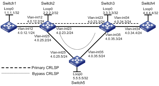
As shown in Figure 1, the primary CRLSP through Switch 1->Switch 2->Switch 3->Switch 4 carries the voice traffic for a company. Multiple Layer 2 switches exist between Switch 2 and Switch 3.
Use MPLS TE FRR to protect the primary CRLSP. When the primary CRLSP fails, FRR can quickly switch traffic to the bypass CRLSP.
Requirements analysis
Use Table 1 to decide the tasks required for fulfilling the requirements.
Table 1 MPLS TE FRR configuration requirements and task matrix
|
Requirements |
Task |
|
Creating the primary and bypass CRLSPs |
Enable MPLS, MPLS TE, and RSVP-TE on the switches. Because the paths for the primary and bypass CRLSPs have been determined, use explicit paths to specify the primary and bypass CRLSPs. |
|
Quick detection of primary CRLSP failure |
Enable BFD for RSVP-TE on Switch 2 and Switch 3. |
|
Quick detection of recovered primary CRLSP |
Set the FRR polling timer. The default timer is 300 seconds. For quicker detection, set a smaller value. In this example, the timer is set to 5 seconds. |
|
Quick failover |
Enable MPLS TE FRR on the ingress node for the traffic to be switched over to the bypass CRLSP when the primary CRLSP fails. |
Software version used
This configuration example was created and verified on S12500-CMW520-R1825P01.
Configuration restrictions and guidelines
When you configure MPLS TE FRR, follow these restrictions and guidelines:
· After you modify the settings for an MPLS TE tunnel interface, you must execute the mpls te commit command to apply the new settings.
· After you create an MPLS TE tunnel, you must configure a route to direct the traffic destined for the tunnel destination to the tunnel.
· If the bandwidth resources are not sufficient, configure FRR only on the key nodes or links to save bandwidth.
· You must configure the bandwidth that the bypass CRLSP can protect with the mpls te backup bandwidth command. Otherwise, the primary and bypass CRLSPs cannot be bound.
· The protection bandwidth configured for the bypass CRLSP must not be less than the bandwidth required by the primary CRLSP. Otherwise, the primary and bypass CRLSPs cannot be bound.
· The bypass CRLSP must not overlap the primary CRLSP except for the ingress and egress nodes.
· The bypass CRLSP must not be used by other services such as VPN.
Configuration procedures
Configuring Switch 1
1. Configure the VLAN interface and loopback interface addresses.
<Switch1> system-view
[Switch1] interface LoopBack 0
[Switch1-LoopBack0] ip address 1.1.1.1 32
[Switch1-LoopBack0] quit
[Switch1] vlan 12
[Switch1-vlan12] port GigabitEthernet 9/0/1
[Switch1-vlan12] quit
[Switch1] interface GigabitEthernet 9/0/1
[Switch1-GigabitEthernet9/0/1] undo shutdown
[Switch1-GigabitEthernet9/0/1] quit
[Switch1] interface Vlan-interface 12
[Switch1-Vlan-interface12] ip address 4.0.12.1 24
[Switch1-Vlan-interface12] undo shutdown
[Switch1-Vlan-interface12] quit
2. Configure the IGP protocol:
# Enable OSPF.
[Switch1] ospf
# Enable the OSPF opaque LSA capability.
[Switch1-ospf-1] opaque-capability enable
# Create an area and advertise VLAN interface and loopback interface addresses.
[Switch1-ospf-1] area 0
[Switch1-ospf-1-area-0.0.0.0] network 1.1.1.1 0.0.0.0
[Switch1-ospf-1-area-0.0.0.0] network 4.0.12.1 0.0.0.0
# Enable MPLS TE for the OSPF area.
[Switch1-ospf-1-area-0.0.0.0] mpls-te enable
[Switch1-ospf-1-area-0.0.0.0] quit
[Switch1-ospf-1] quit
3. Enable MPLS and MPLS TE globally:
# Configure the loopback interface address as the LSR ID.
[Switch1] mpls lsr-id 1.1.1.1
# Enable MPLS, MPLS TE, CSPF, and RSVP-TE globally.
[Switch1] mpls
[Switch1-mpls] mpls te
[Switch1-mpls] mpls te cspf
[Switch1-mpls] mpls rsvp-te
[Switch1-mpls] quit
4. On the VLAN interface, enable MPLS, MPLS TE, and RSVP-TE, and enable BFD for RSVP-TE.
[Switch1] interface Vlan-interface 12
[Switch1-Vlan-interface12] mpls
[Switch1-Vlan-interface12] mpls te
[Switch1-Vlan-interface12] mpls rsvp-te
[Switch1-Vlan-interface12] mpls rsvp-te bfd enable
[Switch1-Vlan-interface12] quit
5. Configure the primary CRLSP:
# Create the primary tunnel interface.
[Switch1] interface Tunnel 0
# Configure an IP address for the primary tunnel interface, so that the line protocol status of the MPLS-TE tunnel does not affect the up/down status of the MPLS-TE tunnel.
[Switch1-Tunnel0] ip address 5.0.0.1 24
# Configure the primary tunnel type as MPLS TE.
[Switch1-Tunnel0] tunnel-protocol mpls te
# Configure a tunnel ID for the primary tunnel.
[Switch1-Tunnel0] mpls te tunnel-id 1
# Configure the destination address of the primary tunnel as the loopback interface address of Switch 4.
[Switch1-Tunnel0] destination 4.4.4.4
[Switch1-Tunnel0] quit
# Configure a static route to direct the traffic destined for 4.4.4.4 to the tunnel.
[Switch1] ip route-static 4.4.4.4 32 Tunnel 0
# Configure an explicit path for the primary CRLSP.
[Switch1] explicit-path pri-path
[Switch1-explicit-path-pri-path] next hop 4.0.12.2
[Switch1-explicit-path-pri-path] next hop 4.0.23.3
[Switch1-explicit-path-pri-path] next hop 4.0.34.4
[Switch1-explicit-path-pri-path] quit
# Apply the configured explicit path with a preference of 5 to the primary tunnel. If a tunnel is configured with multiple explicit paths, it uses the explicit path with the largest preference value.
[Switch1-Tunnel0] mpls te path explicit-path pri-path preference 5
6. Enable MPLS TE FRR:
# Enable MPLS TE FRR on the primary tunnel.
[Switch1-Tunnel0] mpls te fast-reroute
# Submit the primary tunnel configuration to validate the configuration.
[Switch1-Tunnel0] mpls te commit
[Switch1-Tunnel0] quit
Configuring Switch 2
1. Configure IP addresses for the loopback and VLAN interfaces.
<Switch2> system-view
[Switch2] interface LoopBack 0
[Switch2-LoopBack0] ip address 2.2.2.2 32
[Switch2-LoopBack0] quit
[Switch2] vlan 12
[Switch2-vlan12] port GigabitEthernet 9/0/1
[Switch2-vlan12] quit
[Switch2] interface GigabitEthernet 9/0/1
[Switch2-GigabitEthernet9/0/1] undo shutdown
[Switch2-GigabitEthernet9/0/1] quit
[Switch2] interface Vlan-interface 12
[Switch2-Vlan-interface12] ip address 4.0.12.2 24
[Switch2-Vlan-interface12] undo shutdown
[Switch2-Vlan-interface12] quit
[Switch2] vlan 23
[Switch2-vlan23] port GigabitEthernet 9/0/2
[Switch2-vlan23] quit
[Switch2] interface GigabitEthernet 9/0/2
[Switch2-GigabitEthernet9/0/2] undo shutdown
[Switch2-GigabitEthernet9/0/2] quit
[Switch2] interface Vlan-interface 23
[Switch2-Vlan-interface23] ip address 4.0.23.2 24
[Switch2-Vlan-interface23] undo shutdown
[Switch2-Vlan-interface23] quit
[Switch2] vlan25
[Switch2-vlan25] port GigabitEthernet 9/0/3
[Switch2-vlan25] quit
[Switch2] interface GigabitEthernet 9/0/3
[Switch2-GigabitEthernet9/0/3] undo shutdown
[Switch2-GigabitEthernet9/0/3] quit
[Switch2] interface Vlan-interface 25
[Switch2-Vlan-interface25] ip address 4.0.25.2 24
[Switch2-Vlan-interface25] undo shutdown
[Switch2-Vlan-interface25] quit
2. Configure the IGP protocol:
# Enable OSPF.
[Switch2] ospf
# Enable the OSPF opaque LSA capability.
[Switch2-ospf-1] opaque-capability enable
# Create an OSPF area and advertise VLAN interface and loopback interface addresses.
[Switch2-ospf-1] area 0
[Switch2-ospf-1-area-0.0.0.0] network 2.2.2.2 0.0.0.0
[Switch2-ospf-1-area-0.0.0.0] network 4.0.12.2 0.0.0.0
[Switch2-ospf-1-area-0.0.0.0] network 4.0.23.2 0.0.0.0
[Switch2-ospf-1-area-0.0.0.0] network 4.0.25.2 0.0.0.0
# Enable MPLS TE for the OSPF area.
[Switch2-ospf-1-area-0.0.0.0] mpls-te enable
[Switch2-ospf-1-area-0.0.0.0] quit
[Switch2-ospf-1] quit
3. Enable MPLS and MPLS TE globally:
# Configure the loopback interface address as the LSR-ID.
[Switch2] mpls lsr-id 2.2.2.2
# Enable MPLS, MPLS TE, CSPF, and RSVP-TE globally.
[Switch2] mpls
[Switch2-mpls] mpls te
[Switch2-mpls] mpls te cspf
[Switch2-mpls] mpls rsvp-te
# Set the FRR polling timer to 5 seconds.
[Switch2-mpls] mpls te timer fast-reroute 5
[Switch2-mpls] quit
4. On the VLAN interfaces, enable MPLS, MPLS TE, and RSVP-TE, and enable BFD for RSVP-TE.
[Switch2] interface Vlan-interface 12
[Switch2-Vlan-interface12] mpls
[Switch2-Vlan-interface12] mpls te
[Switch2-Vlan-interface12] mpls rsvp-te
[Switch2-Vlan-interface12] mpls rsvp-te bfd enable
[Switch2-Vlan-interface12] quit
[Switch2] interface Vlan-interface 23
[Switch2-Vlan-interface23] mpls
[Switch2-Vlan-interface23] mpls te
[Switch2-Vlan-interface23] mpls rsvp-te
[Switch2-Vlan-interface23] mpls rsvp-te bfd enable
[Switch2-Vlan-interface23] quit
[Switch2] interface Vlan-interface 25
[Switch2-Vlan-interface25] mpls
[Switch2-Vlan-interface25] mpls te
[Switch2-Vlan-interface25] mpls rsvp-te
[Switch2-Vlan-interface25] mpls rsvp-te bfd enable
[Switch2-Vlan-interface25] quit
5. Configure the bypass CRLSP:
# Create the bypass tunnel interface.
[Switch2] interface Tunnel 1
# Configure an IP address for the bypass tunnel interface, so that the line protocol status of the MPLS-TE tunnel does not affect the up/down status of the MPLS-TE tunnel.
[Switch2-Tunnel1] ip address 6.0.0.1 24
# Configure the bypass tunnel type as MPLS TE.
[Switch2-Tunnel1] tunnel-protocol mpls te
# Configure a tunnel ID for the bypass tunnel.
[Switch2-Tunnel1] mpls te tunnel-id 1
# Configure the destination address of the bypass tunnel as the loopback interface address of Switch 3.
[Switch2-Tunnel1] destination 3.3.3.3
# Configure an explicit path for the bypass CR-LSP.
[Switch2] explicit-path by-path
[Switch2-explicit-path-by-path] next hop 4.0.25.5
[Switch2-explicit-path-by-path] next hop 4.0.35.3
[Switch2-explicit-path-by-path] quit
# Apply the explicit path with a preference of 5 to the tunnel. If a tunnel is configured with multiple explicit paths, it uses the explicit path with the largest preference value.
[Switch2-Tunnel1] mpls te path explicit-path by-path preference 5
# Configure the bandwidth that the bypass tunnel protects.
[Switch2-Tunnel1] mpls te backup bandwidth bc0 un-limited
# Submit the bypass tunnel configuration to validate the configuration.
[Switch2-Tunnel0] mpls te commit
[Switch2-Tunnel1] quit
6. Bind the bypass tunnel with the protected interface.
[Switch2] interface Vlan-interface 23
[Switch2-Vlan-interface23] mpls te fast-reroute bypass-tunnel Tunnel1
[Switch2-Vlan-interface23] quit
Configuring Switch 3
1. Configure IP addresses for the loopback and VLAN interfaces.
<Switch3> system-view
[Switch3] interface LoopBack 0
[Switch3-LoopBack0] ip address 3.3.3.3 32
[Switch3-LoopBack0] quit
[Switch3] vlan 23
[Switch3-vlan23] port GigabitEthernet 9/0/1
[Switch3-vlan23] quit
[Switch3] interface GigabitEthernet 9/0/1
[Switch3-GigabitEthernet9/0/1] undo shutdown
[Switch3-GigabitEthernet9/0/1] quit
[Switch3] interface Vlan-interface 23
[Switch3-Vlan-interface23] ip address 4.0.23.3 24
[Switch3-Vlan-interface23] undo shutdown
[Switch3-Vlan-interface23] quit
[Switch3] vlan 34
[Switch3-vlan34] port GigabitEthernet 9/0/2
[Switch3-vlan34] quit
[Switch3] interface GigabitEthernet 9/0/2
[Switch3-GigabitEthernet9/0/2] undo shutdown
[Switch3-GigabitEthernet9/0/2] quit
[Switch3] interface Vlan-interface 34
[Switch3-Vlan-interface34] ip address 4.0.34.3 24
[Switch3-Vlan-interface34] undo shutdown
[Switch3-Vlan-interface34] quit
[Switch3] vlan 35
[Switch3-vlan35] port GigabitEthernet 9/0/3
[Switch3-vlan35] quit
[Switch3] interface GigabitEthernet 9/0/3
[Switch3-GigabitEthernet9/0/3] undo shutdown
[Switch3-GigabitEthernet9/0/3] quit
[Switch3] interface Vlan-interface 35
[Switch3-Vlan-interface35] ip address 4.0.35.3 24
[Switch3-Vlan-interface35] undo shutdown
[Switch3-Vlan-interface35] quit
2. Configure the IGP protocol:
# Enable OSPF.
[Switch3] ospf
# Enable the OSPF opaque LSA capability.
[Switch3-ospf-1] opaque-capability enable
# Create an area, and advertise VLAN interface and loopback interface addresses.
[Switch3-ospf-1] area 0
[Switch3-ospf-1-area-0.0.0.0] network 3.3.3.3 0.0.0.0
[Switch3-ospf-1-area-0.0.0.0] network 4.0.23.3 0.0.0.0
[Switch3-ospf-1-area-0.0.0.0] network 4.0.34.3 0.0.0.0
[Switch3-ospf-1-area-0.0.0.0] network 4.0.35.3 0.0.0.0
# Enable MPLS TE for the OSPF area.
[Switch3-ospf-1-area-0.0.0.0] mpls-te enable
[Switch3-ospf-1-area-0.0.0.0] quit
[Switch3-ospf-1] quit
3. Enable MPLS and MPLS TE globally:
# Configure the loopback interface address as the LSR-ID.
[Switch3] mpls lsr-id 3.3.3.3
# Enable MPLS, MPLS TE, CSPF, and RSVP-TE globally.
[Switch3] mpls
[Switch3-mpls] mpls te
[Switch3-mpls] mpls te cspf
[Switch3-mpls] mpls rsvp-te
[Switch3-mpls] quit
4. On the VLAN interfaces, enable MPLS, MPLS TE, and RSVP-TE, and enable BFD for RSVP-TE.
[Switch3] interface Vlan-interface 23
[Switch3-Vlan-interface23] mpls
[Switch3-Vlan-interface23] mpls te
[Switch3-Vlan-interface23] mpls rsvp-te
[Switch3-Vlan-interface23] mpls rsvp-te bfd enable
[Switch3-Vlan-interface23] quit
[Switch3] interface Vlan-interface 34
[Switch3-Vlan-interface34] mpls
[Switch3-Vlan-interface34] mpls te
[Switch3-Vlan-interface34] mpls rsvp-te
[Switch3-Vlan-interface34] mpls rsvp-te bfd enable
[Switch3-Vlan-interface34] quit
[Switch3] interface Vlan-interface 35
[Switch3-Vlan-interface35] mpls
[Switch3-Vlan-interface35] mpls te
[Switch3-Vlan-interface35] mpls rsvp-te
[Switch3-Vlan-interface35] mpls rsvp-te bfd enable
[Switch3-Vlan-interface35] quit
Configuring Switch 4
1. Configure IP addresses for the loopback and VLAN interfaces.
<Switch4> system-view
[Switch4] interface LoopBack 0
[Switch4-LoopBack0] ip address 4.4.4.4 32
[Switch4-LoopBack0] quit
[Switch4] vlan 34
[Switch4-vlan34] port GigabitEthernet 9/0/1
[Switch4-vlan34] quit
[Switch4] interface GigabitEthernet 9/0/1
[Switch4-GigabitEthernet9/0/1] undo shutdown
[Switch4-GigabitEthernet9/0/1] quit
[Switch4] interface Vlan-interface 34
[Switch4-Vlan-interface34] ip address 4.0.34.4 24
[Switch4-Vlan-interface34] undo shutdown
[Switch4-Vlan-interface34] quit
2. Configure the IGP protocol:
# Enable OSPF.
[Switch4] ospf
# Enable the OSPF opaque LSA capability.
[Switch4-ospf-1] opaque-capability enable
# Create an area, and advertise VLAN interface and loopback interface addresses.
[Switch4-ospf-1] area 0
[Switch4-ospf-1-area-0.0.0.0] network 4.4.4.4 0.0.0.0
[Switch4-ospf-1-area-0.0.0.0] network 4.0.34.4 0.0.0.0
# Enable MPLS TE for the OSPF area.
[Switch4-ospf-1-area-0.0.0.0] mpls-te enable
[Switch4-ospf-1-area-0.0.0.0] quit
3. Enable MPLS and MPLS TE globally:
# Configure the loopback interface address as the LSR-ID.
[Switch4] mpls lsr-id 4.4.4.4
# Enable MPLS, MPLS TE, CSPF, and RSVP-TE globally.
[Switch4] mpls
[Switch4-mpls] mpls te
[Switch4-mpls] mpls te cspf
[Switch4-mpls] mpls rsvp-te
[Switch4-mpls] quit
4. On the VLAN interface, enable MPLS, MPLS TE, and RSVP-TE, and enable BFD for RSVP-TE.
[Switch4] interface Vlan-interface 34
[Switch4-Vlan-interface34] mpls
[Switch4-Vlan-interface34] mpls te
[Switch4-Vlan-interface34] mpls rsvp-te
[Switch4-Vlan-interface34] mpls rsvp-te bfd enable
[Switch4-Vlan-interface34] quit
Configuring Switch 5
1. Configure IP addresses for the loopback and VLAN interfaces.
<Switch5> system-view
[Switch5] interface LoopBack 0
[Switch5-LoopBack0] ip address 5.5.5.5 32
[Switch5-LoopBack0] quit
[Switch5] vlan 25
[Switch5-vlan25] port GigabitEthernet 9/0/1
[Switch5-vlan25] quit
[Switch5] interface GigabitEthernet 9/0/1
[Switch5-GigabitEthernet9/0/1] undo shutdown
[Switch5-GigabitEthernet9/0/1] quit
[Switch5] interface Vlan-interface 25
[Switch5-Vlan-interface25] ip address 4.0.25.5 24
[Switch5-Vlan-interface25] undo shutdown
[Switch5-Vlan-interface25] quit
[Switch5] vlan 35
[Switch5-vlan35] port GigabitEthernet 9/0/2
[Switch5-vlan35] quit
[Switch5] interface GigabitEthernet 9/0/2
[Switch5-GigabitEthernet9/0/2] undo shutdown
[Switch5-GigabitEthernet9/0/2] quit
[Switch5] interface Vlan-interface 35
[Switch5-Vlan-interface35] ip address 4.0.35.5 24
[Switch5-Vlan-interface35] undo shutdown
[Switch5-Vlan-interface35] quit
2. Configure the IGP protocol:
# Enable OSPF.
[Switch5] ospf
# Enable the OSPF opaque LSA capability.
[Switch5-ospf-1] opaque-capability enable
# Create an area, and advertise VLAN interface and loopback interface addresses.
[Switch5-ospf-1] area 0
[Switch5-ospf-1-area-0.0.0.0] network 5.5.5.5 0.0.0.0
[Switch5-ospf-1-area-0.0.0.0] network 4.0.25.5 0.0.0.0
[Switch5-ospf-1-area-0.0.0.0] network 4.0.35.5 0.0.0.0
# Enable MPLS TE for the OSPF area.
[Switch5-ospf-1-area-0.0.0.0] mpls-te enable
[Switch5-ospf-1-area-0.0.0.0] quit
[Switch5-ospf-1] quit
3. Enable MPLS and MPLS TE globally:
# Configure the loopback interface address as the LSR-ID.
[Switch5] mpls lsr-id 5.5.5.5
# Enter MPLS view, and enable MPLS TE, CSPF, and RSVP-TE.
[Switch5] mpls
[Switch5-mpls] mpls te
[Switch5-mpls] mpls te cspf
[Switch5-mpls] mpls rsvp-te
[Switch5-mpls] quit
4. On the VLAN interfaces, enable MPLS, MPLS TE, and RSVP-TE, and enable BFD for RSVP-TE.
[Switch5] interface Vlan-interface 25
[Switch5-Vlan-interface25] mpls
[Switch5-Vlan-interface25] mpls te
[Switch5-Vlan-interface25] mpls rsvp-te
[Switch5-Vlan-interface25] mpls rsvp-te bfd enable
[Switch5-Vlan-interface25] quit
[Switch5] interface Vlan-interface 35
[Switch5-Vlan-interface35] mpls
[Switch5-Vlan-interface35] mpls te
[Switch5-Vlan-interface35] mpls rsvp-te
[Switch5-Vlan-interface35] mpls rsvp-te bfd enable
[Switch5-Vlan-interface35] quit
Verifying the configuration
1. Display the TE tunnel information on Switch 1:
# Execute the display mpls te tunnel-interface Tunnel 0 command on Switch 1 to view the detailed information about the tunnel interface.
[Switch1] display mpls te tunnel-interface Tunnel 0
Tunnel Name : Tunnel0
Tunnel Desc : Tunnel0 Interface
Tunnel State Desc : CR-LSP is Up
Tunnel Attributes :
LSP ID : 1.1.1.1:3
Session ID : 1
Admin State : UP Oper State : UP
Ingress LSR ID : 1.1.1.1 Egress LSR ID: 4.4.4.4
Signaling Prot : RSVP Resv Style : SE
Tunnel mode : -
Class Type : CT0 Tunnel BW : 0 kbps
Reserved BW : 0 kbps
Setup Priority : 7 Hold Priority: 7
Affinity Prop/Mask : 0x0/0x0
Explicit Path Name : pri-path
Tie-Breaking Policy : None
Metric Type : None
Loop Detection : Disabled
Record Route : Enabled Record Label : Enabled
FRR Flag : Enabled BackUpBW Flag: Not Supported
BackUpBW Type : - BackUpBW : -
Route Pinning : Disabled
Retry Limit : 5 Retry Interval: 2 sec
Reopt : Disabled Reopt Freq : -
Back Up Type : None
Back Up LSPID : -
Auto BW : Disabled Auto BW Freq : -
Min BW : - Max BW : -
Current Collected BW: -
Interfaces Protected: -
VPN Bind Type : NONE
VPN Bind Value : -
Car Policy : Disabled
Tunnel Group : Primary
Primary Tunnel : -
Backup Tunnel : -
Group Status : -
2. Display the brief tunnel information on each switch.
[Switch1] display mpls te tunnel
LSP-Id Destination In/Out-If Name
1.1.1.1:1 4.4.4.4 -/Vlan12 Tunnel0
[Switch2] display mpls te tunnel
LSP-Id Destination In/Out-If Name
1.1.1.1:1 4.4.4.4 Vlan12/Vlan23 Tunnel0
2.2.2.2:3 3.3.3.3 -/Vlan25 Tunnel1
[Switch3] display mpls te tunnel
LSP-Id Destination In/Out-If Name
1.1.1.1:1 4.4.4.4 Vlan23/Vlan34 Tunnel0
2.2.2.2:3 3.3.3.3 Vlan35/- Tunnel1
[Switch4] display mpls te tunnel
LSP-Id Destination In/Out-If Name
1.1.1.1:1 4.4.4.4 Vlan34/- Tunnel0
[Switch5] display mpls te tunnel
LSP-Id Destination In/Out-If Name
2.2.2.2:3 3.3.3.3 Vlan25/Vlan35 Tunnel1
The output shows that two tunnels are available on Switch 2 and Switch 3.
3. Display the binding between the primary and bypass tunnels on Switch 2.
[Switch2] display mpls lsp verbose
-------------------------------------------------------------------------
LSP Information: RSVP LSP
-------------------------------------------------------------------------
No. : 1
IngressLsrID : 2.2.2.2
LocalLspID : 1
Tunnel-Interface : Tunnel1
Fec : 3.3.3.3/32
Nexthop : 4.0.25.5
In-Label : NULL
Out-Label : 1024
In-Interface : ----------
Out-Interface : Vlan-interface25
LspIndex : 3073
Tunnel ID : 0x23c002
LsrType : Ingress
Bypass In Use : Not Exists
BypassTunnel : Tunnel Index[---]
No. : 2
IngressLsrID : 1.1.1.1
LocalLspID : 3
Tunnel-Interface : Tunnel0
Fec : 4.4.4.4/32
Nexthop : 4.0.23.3
In-Label : 1026
Out-Label : 1026
In-Interface : Vlan-interface12
Out-Interface : Vlan-interface23
LspIndex : 3076
Tunnel ID : 0x23c005
LsrType : Transit
Bypass In Use : Not Used
BypassTunnel : Tunnel Index[Tunnel1], InnerLabel[1026]
The output shows that the bypass tunnel is bound to VLAN-interface 23 and it is not used.
4. View BFD sessions on switches:
If BFD for RSVP is enabled on the two VLAN interfaces of a link, a BFD session is established to detect the status of the link.
# Display BFD information on the switches.
[Switch1] display bfd session
Total Session Num: 1 Init Mode: Active
Session Working Under Ctrl Mode:
LD/RD SourceAddr DestAddr State Holdtime Interface
3/16 4.0.12.1 4.0.12.2 Up 1800ms Vlan12
[Switch2] display bfd session
Total Session Num: 3 Init Mode: Active
Session Working Under Ctrl Mode:
LD/RD SourceAddr DestAddr State Holdtime Interface
7/3 4.0.25.2 4.0.25.5 Up 1600ms Vlan25
16/3 4.0.12.2 4.0.12.1 Up 1800ms Vlan12
17/8 4.0.23.2 4.0.23.3 Up 1900ms Vlan23
[Switch3] display bfd session
Total Session Num: 3 Init Mode: Active
Session Working Under Ctrl Mode:
LD/RD SourceAddr DestAddr State Holdtime Interface
6/4 4.0.35.3 4.0.35.5 Up 1900ms Vlan35
8/17 4.0.23.3 4.0.23.2 Up 1900ms Vlan23
9/4 4.0.34.3 4.0.34.4 Up 1900ms Vlan34
[Switch4] display bfd session
Total Session Num: 1 Init Mode: Active
Session Working Under Ctrl Mode:
LD/RD SourceAddr DestAddr State Holdtime Interface
4/9 4.0.34.4 4.0.34.3 Up 1700ms Vlan34
[Switch5] display bfd session
Total Session Num: 2 Init Mode: Active
Session Working Under Ctrl Mode:
LD/RD SourceAddr DestAddr State Holdtime Interface
3/7 4.0.25.5 4.0.25.2 Up 1800ms Vlan25
4/6 4.0.35.5 4.0.35.3 Up 1700ms Vlan35
# Display the detailed information about BFD sessions on Switch 2.
[Switch2] display bfd session verbose
Total Session Num: 3 Init Mode: Active
Session Working Under Ctrl Mode:
Local Discr: 7 Remote Discr: 3
Source IP: 4.0.25.2 Destination IP: 4.0.25.5
Session State: Up Interface: Vlan-interface25
Min Trans Inter: 400ms Act Trans Inter: 400ms
Min Recv Inter: 400ms Act Detect Inter: 2000ms
Running Up for: 00:57:04 Auth mode: None
Connect Type: Direct Board Num: 6
Protocol: RSVP
Diag Info: No Diagnostic
Local Discr: 16 Remote Discr: 3
Source IP: 4.0.12.2 Destination IP: 4.0.12.1
Session State: Up Interface: Vlan-interface12
Min Trans Inter: 400ms Act Trans Inter: 400ms
Min Recv Inter: 400ms Act Detect Inter: 2000ms
Running Up for: 00:05:44 Auth mode: None
Connect Type: Direct Board Num: 6
Protocol: RSVP
Diag Info: No Diagnostic
Local Discr: 17 Remote Discr: 8
Source IP: 4.0.23.2 Destination IP: 4.0.23.3
Session State: Up Interface: Vlan-interface23
Min Trans Inter: 400ms Act Trans Inter: 400ms
Min Recv Inter: 400ms Act Detect Inter: 2000ms
Running Up for: 00:05:44 Auth mode: None
Connect Type: Direct Board Num: 6
Protocol: RSVP/MFW
Diag Info: No Diagnostic
5. Perform an FRR switchover:
# Shut down the protected interface VLAN-interface 23 on Switch 2.
[Switch2] interface Vlan-interface 23
[Switch2-Vlan-interface23] shutdown
[Switch2-Vlan-interface23] quit
[Switch2] display mpls te tunnel
LSP-Id Destination In/Out-If Name
1.1.1.1:1 4.4.4.4 Vlan12/Vlan23 Tunnel0
2.2.2.2:3 3.3.3.3 -/Vlan25 Tunnel1
# Display detailed LSP information on Switch 2. The output shows that the bypass tunnel is in use.
[Switch2] display mpls lsp verbose
-------------------------------------------------------------------------
LSP Information: RSVP LSP
-------------------------------------------------------------------------
No. : 1
IngressLsrID : 2.2.2.2
LocalLspID : 1
Tunnel-Interface : Tunnel1
Fec : 3.3.3.3/32
Nexthop : 4.0.25.5
In-Label : NULL
Out-Label : 1024
In-Interface : ----------
Out-Interface : Vlan-interface25
LspIndex : 3073
Tunnel ID : 0x23c002
LsrType : Ingress
Bypass In Use : Not Exists
BypassTunnel : Tunnel Index[---]
No. : 2
IngressLsrID : 1.1.1.1
LocalLspID : 3
Tunnel-Interface : Tunnel0
Fec : 4.4.4.4/32
Nexthop : 4.0.23.3
In-Label : 1026
Out-Label : 1026
In-Interface : Vlan-interface12
Out-Interface : Vlan-interface23
LspIndex : 3076
Tunnel ID : 0x23c005
LsrType : Transit
Bypass In Use : In Use
BypassTunnel : Tunnel Index[Tunnel1] , InnerLabel[1026]
Configuration files
· Switch 1:
[Switch1] display current-configuration
#
sysname Switch1
#
mpls lsr-id 1.1.1.1
#
vlan 1
#
vlan 12
#
mpls
mpls te
mpls rsvp-te
mpls te cspf
#
explicit-path pri-path
next hop 4.0.12.2
next hop 4.0.23.3
next hop 4.0.34.4
#
interface NULL0
#
interface LoopBack0
ip address 1.1.1.1 255.255.255.255
#
interface Vlan-interface12
ip address 4.0.12.1 255.255.255.0
mpls
mpls te
mpls rsvp-te
mpls rsvp-te bfd enable
#
interface GigabitEthernet9/0/1
port link-type trunk
undo port trunk permit vlan 1
port trunk permit vlan 12
#
interface Tunnel0
ip address 5.0.0.1 255.255.255.0
tunnel-protocol mpls te
destination 4.4.4.4
mpls te tunnel-id 1
mpls te record-route label
mpls te path explicit-path pri-path preference 5
mpls te fast-reroute
mpls te commit
#
ip route-static 4.4.4.4 255.255.255.255 Tunnel0
#
ospf 1
opaque-capability enable
area 0.0.0.0
network 1.1.1.1 0.0.0.0
network 4.0.12.1 0.0.0.0
mpls-te enable
#
· Switch 2:
[Switch2] display current-configuration
#
sysname Switch2
#
mpls lsr-id 2.2.2.2
#
vlan 1
#
vlan 12
#
vlan 23
#
vlan 25
#
mpls
mpls te
mpls te timer fast-reroute 5
mpls rsvp-te
mpls te cspf
#
explicit-path by-path
next hop 4.0.25.5
next hop 4.0.35.3
#
interface NULL0
#
interface LoopBack0
ip address 2.2.2.2 255.255.255.255
#
interface Vlan-interface12
ip address 4.0.12.2 255.255.255.0
mpls
mpls te
mpls rsvp-te
mpls rsvp-te bfd enable
#
interface Vlan-interface23
ip address 4.0.23.2 255.255.255.0
mpls
mpls te
mpls te fast-reroute bypass-tunnel Tunnel1
mpls rsvp-te
mpls rsvp-te bfd enable
#
interface Vlan-interface25
ip address 4.0.25.2 255.255.255.0
mpls
mpls te
mpls rsvp-te
mpls rsvp-te bfd enable
#
interface GigabitEthernet9/0/1
port link-type trunk
undo port trunk permit vlan 1
port trunk permit vlan 12
#
interface GigabitEthernet9/0/2
port link-type trunk
undo port trunk permit vlan 1
port trunk permit vlan 23
#
interface GigabitEthernet9/0/3
port link-type trunk
undo port trunk permit vlan 1
port trunk permit vlan 25
#
interface Tunnel1
ip address 6.0.0.1 255.255.255.0
tunnel-protocol mpls te
destination 3.3.3.3
mpls te tunnel-id 1
mpls te record-route
mpls te path explicit-path by-path preference 5
mpls te backup bandwidth bc0 un-limited
mpls te commit
#
ospf 1
opaque-capability enable
area 0.0.0.0
network 2.2.2.2 0.0.0.0
network 4.0.12.2 0.0.0.0
network 4.0.23.2 0.0.0.0
network 4.0.25.2 0.0.0.0
mpls-te enable
#
· Switch 3:
[Switch3] display current-configuration
#
sysname Switch3
#
mpls lsr-id 3.3.3.3
#
vlan 1
#
vlan 23
#
vlan 34 to 35
#
mpls
mpls te
mpls rsvp-te
mpls te cspf
#
interface NULL0
#
interface LoopBack0
ip address 3.3.3.3 255.255.255.255
#
interface Vlan-interface23
ip address 4.0.23.3 255.255.255.0
mpls
mpls te
mpls rsvp-te
mpls rsvp-te bfd enable
#
interface Vlan-interface34
ip address 4.0.34.3 255.255.255.0
mpls
mpls te
mpls rsvp-te
mpls rsvp-te bfd enable
#
interface Vlan-interface35
ip address 4.0.35.3 255.255.255.0
mpls
mpls te
mpls rsvp-te
mpls rsvp-te bfd enable
#
interface GigabitEthernet9/0/1
port link-type trunk
undo port trunk permit vlan 1
port trunk permit vlan 23
#
interface GigabitEthernet9/0/2
port link-type trunk
undo port trunk permit vlan 1
port trunk permit vlan 34
#
interface GigabitEthernet9/0/3
port link-type trunk
undo port trunk permit vlan 1
port trunk permit vlan 35
#
ospf 1
opaque-capability enable
area 0.0.0.0
network 3.3.3.3 0.0.0.0
network 4.0.23.3 0.0.0.0
network 4.0.34.3 0.0.0.0
network 4.0.35.3 0.0.0.0
mpls-te enable
#
· Switch 4:
[Switch4] display current-configuration
#
sysname Switch4
#
mpls lsr-id 4.4.4.4
#
vlan 1
#
vlan 34
#
mpls
mpls te
mpls rsvp-te
mpls te cspf
#
interface NULL0
#
interface LoopBack0
ip address 4.4.4.4 255.255.255.255
#
interface Vlan-interface34
ip address 4.0.34.4 255.255.255.0
mpls
mpls te
mpls rsvp-te
mpls rsvp-te bfd enable
#
interface GigabitEthernet9/0/1
port link-type trunk
undo port trunk permit vlan 1
port trunk permit vlan 34
#
ospf 1
opaque-capability enable
area 0.0.0.0
network 4.4.4.4 0.0.0.0
network 4.0.34.4 0.0.0.0
mpls-te enable
#
· Switch 5:
[Switch5] display current-configuration
#
sysname Switch5
#
mpls lsr-id 5.5.5.5
#
vlan 1
#
vlan 25
#
vlan 35
#
mpls
mpls te
mpls rsvp-te
mpls te cspf
#
interface NULL0
#
interface LoopBack0
ip address 5.5.5.5 255.255.255.255
#
interface Vlan-interface25
ip address 4.0.25.5 255.255.255.0
mpls
mpls te
mpls rsvp-te
mpls rsvp-te bfd enable
#
interface Vlan-interface35
ip address 4.0.35.5 255.255.255.0
mpls
mpls te
mpls rsvp-te
mpls rsvp-te bfd enable
#
interface GigabitEthernet9/0/1
port link-type trunk
undo port trunk permit vlan 1
port trunk permit vlan 25
#
interface GigabitEthernet9/0/2
port link-type trunk
undo port trunk permit vlan 1
port trunk permit vlan 35
#
ospf 1
opaque-capability enable
area 0.0.0.0
network 5.5.5.5 0.0.0.0
network 4.0.35.5 0.0.0.0
network 4.0.25.5 0.0.0.0
mpls-te enable
#
Related documentation
· H3C S12500 Routing Switch Series MPLS Configuration Guide
· H3C S12500 Routing Switch Series MPLS Command Reference