- Table of Contents
- Related Documents
-
| Title | Size | Download |
|---|---|---|
| 00-S12500_CRLSP_Backup_Configuration_Examples | 124.73 KB |
Introduction
This document provides CRLSP backup configuration examples.
CRLSP backup provides end-to-end CRLSP protection. When the ingress node detects that the primary CRLSP fails, it switches traffic to the bypass CRLSP. When the primary CRLSP recovers, the ingress node switches traffic back to the primary CRLSP.
The following CRLSP backup methods are available:
· Hot backup—Creates the bypass CRLSP after creating the primary CRLSP, and switches traffic to the bypass CRLSP when the primary CRLSP fails.
· Ordinary backup—Creates the bypass CRLSP after the primary CRLSP fails.
Prerequisites
The configuration examples in this document were created and verified in a lab environment, and all the devices started with the factory default configuration. When you are working in a live network, make sure you understand the potential impact of every command on your network.
This document assumes that you have basic knowledge of CRLSP.
Example: Configuring CRLSP hot backup
Network requirements
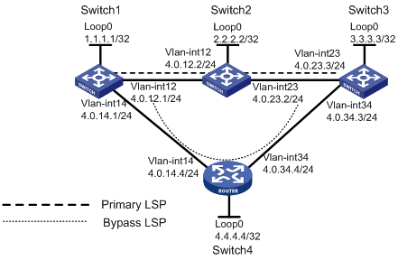
As shown in Figure 1, establish two CRLSPs between Switch 1 and Switch 3. The primary CRLSP passes through Switch1->Switch2->Switch3. The bypass CRLSP is calculated by RSVP-TE. When the primary CRLSP fails, traffic can be immediately switched to the bypass CRLSP.
Requirements analysis
To immediately switch traffic to the bypass CRLSP when the primary CRLSP fails, configure hot CRLSP backup on the ingress node of the primary CRLSP.
To establish the primary and bypass CRLSPs, enable MPLS, MPLS-TE, and RSVP-TE on the switches.
To enable the ingress node to quickly detect the failure of the primary CRLSP, configure BFD for RSVP on each node on the primary CRLSP.
Software version used
This configuration example was created and verified on S12500-CMW520-R1825P01.
Configuration restrictions and guidelines
After you modify the settings for an MPLS TE tunnel interface, you must execute the mpls te commit command to apply the new settings.
After you create an MPLS TE tunnel, you must configure a route to direct the traffic destined for the tunnel destination (3.3.3.3 in this example) to the tunnel.
Configuration procedures
Configuring Switch 1
1. Configure IP addresses for the loopback and VLAN interfaces.
<Switch1> system-view
[Switch1] interface LoopBack 0
[Switch1-LoopBack0] ip address 1.1.1.1 32
[Switch1-LoopBack0] quit
[Switch1] vlan 12
[Switch1-vlan12] port GigabitEthernet 9/0/2
[Switch1-vlan12] quit
[Switch1] interface GigabitEthernet 9/0/2
[Switch1-GigabitEthernet9/0/2] undo shutdown
[Switch1-GigabitEthernet9/0/2] quit
[Switch1] interface Vlan-interface 12
[Switch1-Vlan-interface12] ip address 4.0.12.1 24
[Switch1-Vlan-interface12] undo shutdown
[Switch1-Vlan-interface12] quit
[Switch1] vlan 14
[Switch1-vlan14] port GigabitEthernet 9/0/1
[Switch1-vlan14] quit
[Switch1] interface GigabitEthernet 9/0/1
[Switch1-GigabitEthernet9/0/1] undo shutdown
[Switch1-GigabitEthernet9/0/1] quit
[Switch1] interface Vlan-interface 14
[Switch1-Vlan-interface14] ip address 4.0.14.1 24
[Switch1-Vlan-interface14] undo shutdown
[Switch1-Vlan-interface14] quit
2. Configure the IGP protocol:
# Enable OSPF.
[Switch1] ospf
# Enable the OSPF opaque LSA capability.
[Switch1-ospf-1] opaque-capability enable
# Create an area and advertise VLAN interface and loopback interface addresses.
[Switch1-ospf-1] area 0
[Switch1-ospf-1-area-0.0.0.0] network 1.1.1.1 0.0.0.0
[Switch1-ospf-1-area-0.0.0.0] network 4.0.12.1 0.0.0.0
[Switch1-ospf-1-area-0.0.0.0] network 4.0.14.1 0.0.0.0
# Enable MPLS TE for the OSPF area.
[Switch1-ospf-1-area-0.0.0.0] mpls-te enable
[Switch1-ospf-1-area-0.0.0.0] quit
[Switch1-ospf-1] quit
3. Enable MPLS and MPLS TE globally:
# Configure the loopback interface address as the LSR ID.
[Switch1] mpls lsr-id 1.1.1.1
# Enable MPLS, MPLS TE, CSPF, and RSVP-TE in MPLS view.
[Switch1] mpls
[Switch1-mpls] mpls te
[Switch1-mpls] mpls te cspf
[Switch1-mpls] mpls rsvp-te
[Switch1-mpls] quit
4. On the VLAN interfaces, enable MPLS, MPLS TE, and RSVP-TE, and enable BFD for RSVP-TE.
[Switch1] interface Vlan-interface 12
[Switch1-Vlan-interface12] mpls
[Switch1-Vlan-interface12] mpls te
[Switch1-Vlan-interface12] mpls rsvp-te
[Switch1-Vlan-interface12] mpls rsvp-te bfd enable
[Switch1-Vlan-interface12] quit
[Switch1] interface Vlan-interface 14
[Switch1-Vlan-interface14] mpls
[Switch1-Vlan-interface14] mpls te
[Switch1-Vlan-interface14] mpls rsvp-te
[Switch1-Vlan-interface14] mpls rsvp-te bfd enable
[Switch1-Vlan-interface14] quit
5. Create an MPLS TE tunnel carried on the primary CRLSP, and enable CRLSP hot backup:
# Create the primary tunnel interface.
[Switch1] interface Tunnel 0
# Configure an IP address for the primary tunnel interface, so that the line protocol status of the MPLS-TE tunnel interface does not affect the up/down status of the MPLS-TE tunnel.
[Switch1-Tunnel0] ip address 5.0.0.1 24
# Configure the primary tunnel type as MPLS TE.
[Switch1-Tunnel0] tunnel-protocol mpls te
[Switch1-Tunnel0] quit
# Configure a static route to direct the traffic destined for 3.3.3.3 to the tunnel interface.
[Switch1] ip route-static 3.3.3.3 32 Tunnel 0
# Configure an explicit path for the primary CRLSP.
[Switch1] explicit-path pri-path
[Switch1-explicit-path-pri-path] next hop 4.0.12.2
[Switch1-explicit-path-pri-path] next hop 4.0.23.3
[Switch1-explicit-path-pri-path] quit
# Apply the explicit path with a preference of 5 to the tunnel. If a tunnel is configured with multiple explicit paths, it uses the explicit path with the largest preference value.
[Switch1] interface Tunnel 0
[Switch1-Tunnel0] mpls te path explicit-path pri-path preference 5
# Configure a tunnel ID for the tunnel.
[Switch1-Tunnel0] mpls te tunnel-id 1
# Configure the destination address of the primary tunnel as the loopback interface address of Switch 3.
[Switch1-Tunnel0] destination 3.3.3.3
# Enable CRLSP hot backup.
[Switch1-Tunnel0] mpls te backup hot-standby
# Submit the tunnel configuration to validate the configuration.
[Switch1-Tunnel0] mpls te commit
[Switch1-Tunnel0] quit
Configuring Switch 2
1. Configure IP addresses for the loopback and VLAN interfaces.
<Switch2> system-view
[Switch2] interface LoopBack 0
[Switch2-LoopBack0] ip address 2.2.2.2 32
[Switch2-LoopBack0] quit
[Switch2] vlan 12
[Switch2-vlan12] port GigabitEthernet 9/0/1
[Switch2-vlan12] quit
[Switch2] interface GigabitEthernet 9/0/1
[Switch2-GigabitEthernet9/0/1] undo shutdown
[Switch2-GigabitEthernet9/0/1] quit
[Switch2] interface Vlan-interface 12
[Switch2-Vlan-interface12] ip address 4.0.12.2 24
[Switch2-Vlan-interface12] undo shutdown
[Switch2-Vlan-interface12] quit
[Switch2] vlan 23
[Switch2-vlan23] port GigabitEthernet 9/0/2
[Switch2-vlan23] quit
[Switch2] interface GigabitEthernet 9/0/2
[Switch2-GigabitEthernet9/0/2] undo shutdown
[Switch2-GigabitEthernet9/0/2] quit
[Switch2] interface Vlan-interface 23
[Switch2-Vlan-interface23] ip address 4.0.23.2 24
[Switch2-Vlan-interface23] undo shutdown
[Switch2-Vlan-interface23] quit
2. Configure the IGP protocol:
# Enable OSPF.
[Switch2] ospf
# Enable the OSPF opaque LSA capability.
[Switch2-ospf-1] opaque-capability enable
# Create an area and advertise VLAN interface and loopback interface addresses.
[Switch2-ospf-1] area 0
[Switch2-ospf-1-area-0.0.0.0] network 2.2.2.2 0.0.0.0
[Switch2-ospf-1-area-0.0.0.0] network 4.0.12.2 0.0.0.0
[Switch2-ospf-1-area-0.0.0.0] network 4.0.23.2 0.0.0.0
# Enable MPLS TE for the OSPF area.
[Switch2-ospf-1-area-0.0.0.0] mpls-te enable
[Switch2-ospf-1-area-0.0.0.0] quit
[Switch2-ospf-1] quit
3. Enable MPLS and MPLS TE globally:
# Configure the loopback interface address as the LSR-ID.
[Switch2] mpls lsr-id 2.2.2.2
# Enable MPLS TE, CSPF, and RSVP-TE globally.
[Switch2] mpls
[Switch2-mpls] mpls te
[Switch2-mpls] mpls te cspf
[Switch2-mpls] mpls rsvp-te
[Switch2-mpls] quit
4. On the VLAN interfaces, enable MPLS, MPLS TE, and RSVP-TE, and enable BFD for RSVP-TE.
[Switch2] interface Vlan-interface 12
[Switch2-Vlan-interface12] mpls
[Switch2-Vlan-interface12] mpls te
[Switch2-Vlan-interface12] mpls rsvp-te
[Switch2-Vlan-interface12] mpls rsvp-te bfd enable
[Switch2-Vlan-interface12] quit
[Switch2] interface Vlan-interface 23
[Switch2-Vlan-interface23] mpls
[Switch2-Vlan-interface23] mpls te
[Switch2-Vlan-interface23] mpls rsvp-te
[Switch2-Vlan-interface23] mpls rsvp-te bfd enable
[Switch2-Vlan-interface23] quit
Configuring Switch 3
1. Configure IP addresses for the loopback and VLAN interfaces.
<Switch3> system-view
[Switch3] interface LoopBack 0
[Switch3-LoopBack0] ip address 3.3.3.3 32
[Switch3-LoopBack0] quit
[Switch3] vlan 23
[Switch3-vlan23] port GigabitEthernet 9/0/1
[Switch3-vlan23] quit
[Switch3] interface GigabitEthernet 9/0/1
[Switch3-GigabitEthernet9/0/1] undo shutdown
[Switch3-GigabitEthernet9/0/1] quit
[Switch3] interface Vlan-interface 23
[Switch3-Vlan-interface23] ip address 4.0.23.3 24
[Switch3-Vlan-interface23] undo shutdown
[Switch3-Vlan-interface23] quit
[Switch3] vlan 34
[Switch3-vlan34] port GigabitEthernet 9/0/2
[Switch3-vlan34] quit
[Switch3] interface GigabitEthernet 9/0/2
[Switch3-GigabitEthernet9/0/2] undo shutdown
[Switch3-GigabitEthernet9/0/2] quit
[Switch3] interface Vlan-interface 34
[Switch3-Vlan-interface34] ip address 4.0.34.3 24
[Switch3-Vlan-interface34] undo shutdown
[Switch3-Vlan-interface34] quit
2. Configure the IGP protocol:
# Enable OSPF.
[Switch3] ospf
# Enable the OSPF opaque LSA capability.
[Switch3-ospf-1] opaque-capability enable
# Create an area and advertise VLAN interface and loopback interface addresses.
[Switch3-ospf-1] area 0
[Switch3-ospf-1-area-0.0.0.0] network 3.3.3.3 0.0.0.0
[Switch3-ospf-1-area-0.0.0.0] network 4.0.23.3 0.0.0.0
[Switch3-ospf-1-area-0.0.0.0] network 4.0.34.3 0.0.0.0
# Enable MPLS TE for the OSPF area.
[Switch3-ospf-1-area-0.0.0.0] mpls-te enable
[Switch3-ospf-1-area-0.0.0.0] quit
[Switch3-ospf-1] quit
3. Enable MPLS and MPLS TE globally:
# Configure the loopback interface address as the LSR-ID.
[Switch3] mpls lsr-id 3.3.3.3
# Enable MPLS TE, CSPF, and RSVP-TE globally.
[Switch3] mpls
[Switch3-mpls] mpls te
[Switch3-mpls] mpls te cspf
[Switch3-mpls] mpls rsvp-te
[Switch3-mpls] quit
4. On the VLAN interfaces, enable MPLS, MPLS TE, and RSVP-TE, and enable BFD for RSVP-TE.
[Switch3] interface Vlan-interface 23
[Switch3-Vlan-interface23] mpls
[Switch3-Vlan-interface23] mpls te
[Switch3-Vlan-interface23] mpls rsvp-te
[Switch1-Vlan-interface23] mpls rsvp-te bfd enable
[Switch3-Vlan-interface23] quit
[Switch3] interface Vlan-interface 34
[Switch3-Vlan-interface34] mpls
[Switch3-Vlan-interface34] mpls te
[Switch3-Vlan-interface34] mpls rsvp-te
[Switch1-Vlan-interface34] mpls rsvp-te bfd enable
[Switch3-Vlan-interface34] quit
Configuring Switch 4
1. Configure IP addresses for the loopback and VLAN interfaces.
<Switch4> system-view
[Switch4] interface LoopBack 0
[Switch4-LoopBack0] ip address 4.4.4.4 32
[Switch4-LoopBack0] quit
[Switch4] vlan 14
[Switch4-vlan14] port GigabitEthernet 9/0/1
[Switch4-vlan14] quit
[Switch4] interface GigabitEthernet 9/0/1
[Switch4-GigabitEthernet9/0/1] undo shutdown
[Switch4-GigabitEthernet9/0/1] quit
[Switch4] interface Vlan-interface 14
[Switch4-Vlan-interface14] ip address 4.0.14.4 24
[Switch4-Vlan-interface14] undo shutdown
[Switch4-Vlan-interface14] quit
[Switch4] vlan 34
[Switch4-vlan34] port GigabitEthernet 9/0/2
[Switch4-vlan34] quit
[Switch4] interface GigabitEthernet 9/0/2
[Switch4-GigabitEthernet9/0/2] undo shutdown
[Switch4-GigabitEthernet9/0/2] quit
[Switch4] interface Vlan-interface 34
[Switch4-Vlan-interface34] ip address 4.0.34.4 24
[Switch4-Vlan-interface34] undo shutdown
[Switch4-Vlan-interface34] quit
2. Configure the IGP protocol:
# Enable OSPF.
[Switch4] ospf
# Enable the OSPF opaque LSA capability.
[Switch4-ospf-1] opaque-capability enable
# Create an area and advertise VLAN interface and loopback interface addresses.
[Switch4-ospf-1] area 0
[Switch4-ospf-1-area-0.0.0.0] network 4.4.4.4 0.0.0.0
[Switch4-ospf-1-area-0.0.0.0] network 4.0.14.4 0.0.0.0
[Switch4-ospf-1-area-0.0.0.0] network 4.0.34.4 0.0.0.0
# Enable MPLS TE for the OSPF area.
[Switch4-ospf-1-area-0.0.0.0] mpls-te enable
[Switch4-ospf-1-area-0.0.0.0] quit
[Switch4-ospf-1] quit
3. Enable MPLS and MPLS TE globally:
# Configure the loopback interface address as the LSR-ID.
[Switch4] mpls lsr-id 4.4.4.4
# Enable MPLS, MPLS TE, CSPF, and RSVP-TE globally.
[Switch4] mpls
[Switch4-mpls] mpls te
[Switch4-mpls] mpls te cspf
[Switch4-mpls] mpls rsvp-te
[Switch4-mpls] quit
4. On the VLAN interfaces, enable MPLS, MPLS TE, and RSVP-TE, and enable BFD for RSVP-TE.
[Switch4] interface Vlan-interface 14
[Switch4-Vlan-interface14] mpls
[Switch4-Vlan-interface14] mpls te
[Switch4-Vlan-interface14] mpls rsvp-te
[Switch4-Vlan-interface14] mpls rsvp-te bfd enable
[Switch4-Vlan-interface14] quit
[Switch4] interface Vlan-interface 34
[Switch4-Vlan-interface34] mpls
[Switch4-Vlan-interface34] mpls te
[Switch4-Vlan-interface34] mpls rsvp-te
[Switch4-Vlan-interface34] mpls rsvp-te bfd enable
[Switch4-Vlan-interface34] quit
Verifying the configuration
Follow these steps to verify your configuration on Switch 1.
1. Display CRLSP information on Switch 1.
# Execute the display mpls te tunnel command to view the two CRLSPs for hot backup.
[Switch1] display mpls te tunnel
LSP-Id Destination In/Out-If Name
1.1.1.1:14 3.3.3.3 -/Vlan12 Tunnel0
1.1.1.1:16 3.3.3.3 -/Vlan14 Tunnel0
# Execute the display mpls te tunnel path command to view the paths that the two CRLSPs traverse.
[Switch1] display mpls te tunnel path
Tunnel Interface Name : Tunnel0
Lsp ID : 1.1.1.1 :14
Hop Information
Hop 0 4.0.12.1
Hop 1 4.0.12.2
Hop 2 2.2.2.2
Hop 3 4.0.23.2
Hop 4 4.0.23.3
Hop 5 3.3.3.3
Tunnel Interface Name : Tunnel0
Lsp ID : 1.1.1.1 :16
Hop Information
Hop 0 4.0.14.1
Hop 1 4.0.14.4
Hop 2 4.4.4.4
Hop 3 4.0.34.4
Hop 4 4.0.34.3
Hop 5 3.3.3.3
# Execute the display mpls te tunnel-interface command to view detailed tunnel interface information.
[Switch1] display mpls te tunnel-interface
Tunnel Name : Tunnel0
Tunnel Desc : Tunnel0 Interface
Tunnel State Desc : Primary CR-LSP Up and HotBackup CR-LSP Up
Tunnel Attributes :
LSP ID : 1.1.1.1:14
Session ID : 1
Admin State : UP Oper State : UP
Ingress LSR-ID : 1.1.1.1 Egress LSR-ID: 3.3.3.3
Signaling Prot : RSVP Resv Style : SE
Class Type : CLASS 0 Tunnel BW : 0 kbps
Reserved BW : 0 kbps
Setup Priority : 7 Hold Priority: 7
Affinity Prop/Mask : 0x0/0x0
Explicit Path Name : pri-path
Tie-Breaking Policy : None
Metric Type : None
Loop Detection : Disabled
Record Route : Enabled Record Label : Disabled
FRR Flag : Disabled BackUpBW Flag: Not Supported
BackUpBW Type : - BackUpBW : -
Route Pinning : Disabled
Retry Limit : 5 Retry Interval: 2 sec
Reopt : Disabled Reopt Freq : -
Back Up Type : HotStandBy
Back Up LSPID : 1.1.1.1:16
Auto BW : Disabled Auto BW Freq : -
Min BW : - Max BW : -
Current Collected BW: -
Interfaces Protected: -
VPN Bind Type : NONE
VPN Bind Value : -
Car Policy : Disabled
Tunnel Group : Primary
Primary Tunnel : -
Backup Tunnel : -
Group Status : -
Oam Status : Up
2. View BFD session information:
# Execute the display bfd session command to view the BFD information on the switches.
[Switch1] display bfd session
Total session number: 2 Up session number: 2 Init mode: Active
IPv4 session working under Ctrl mode:
LD/RD SourceAddr DestAddr State Holdtime Interface
1/1 4.0.12.1 4.0.12.2 Up 1900ms Vlan12
2/1 4.0.14.1 4.0.14.4 Up 2000ms Vlan14
[Switch2] display bfd session
Total session number: 2 Up session number: 2 Init mode: Active
IPv4 session working under Ctrl mode:
LD/RD SourceAddr DestAddr State Holdtime Interface
1/1 4.0.12.2 4.0.12.1 Up 1900ms Vlan12
2/1 4.0.23.2 4.0.23.3 Up 1800ms Vlan23
[Switch3] display bfd session
Total session number: 2 Up session number: 2 Init mode: Active
IPv4 session working under Ctrl mode:
LD/RD SourceAddr DestAddr State Holdtime Interface
1/2 4.0.23.3 4.0.23.2 Up 2000ms Vlan23
2/2 4.0.34.3 4.0.34.4 Up 1700ms Vlan34
[Switch4] display bfd session
Total session number: 2 Up session number: 2 Init mode: Active
IPv4 session working under Ctrl mode:
LD/RD SourceAddr DestAddr State Holdtime Interface
1/2 4.0.14.4 4.0.14.1 Up 1800ms Vlan14
2/2 4.0.34.4 4.0.34.3 Up 1900ms Vlan34
# Execute the display bfd session verbose command on Switch 1 to view the detailed information of the BFD sessions.
[Switch1] display bfd session verbose
Total Session Num: 2 Init Mode: Active
Session Working Under Ctrl Mode:
Local Discr: 1 Remote Discr: 1
Source IP: 4.0.12.1 Destination IP: 4.0.12.2
Session State: Up Interface: Vlan-interface12
Min Trans Inter: 400ms Act Trans Inter: 400ms
Min Recv Inter: 400ms Act Detect Inter: 2000ms
Running Up for: 00:01:36 Auth mode: None
Connect Type: Direct Board Num: 6
Protocol: RSVP
Diag Info: No Diagnostic
Local Discr: 2 Remote Discr: 1
Source IP: 4.0.14.1 Destination IP: 4.0.14.4
Session State: Up Interface: Vlan-interface14
Min Trans Inter: 400ms Act Trans Inter: 400ms
Min Recv Inter: 400ms Act Detect Inter: 2000ms
Running Up for: 00:01:36 Auth mode: None
Connect Type: Direct Board Num: 6
Protocol: RSVP
Diag Info: No Diagnostic
The output shows that RSVP has been associated with the BFD sessions.
3. Perform a CRLSP active/standby switchover:
# Use the tracert lsp command to view the path that a packet travels to reach the tunnel destination.
[Switch1] tracert lsp -a 1.1.1.1 te Tunnel 0
LSP Trace Route FEC: TE TUNNEL IPV4 SESSION QUERY Tunnel0 , press CTRL_C to bre
ak.
TTL Replier Time Type Downstream
0 Ingress 4.0.12.2/[1028]
1 4.0.12.2 58 ms Transit 4.0.23.3/[3]
2 4.0.23.3 60 ms Egress
The output shows that the CRLSP passing Switch 2 is used.
# Shut down the interface VLAN-interface 12 of Switch 1 to trigger an active/standby switchover.
[Switch1] interface Vlan-interface12
[Switch1-Vlan-interface12] shutdown
[Switch1-Vlan-interface12] quit
[Switch1-Vlan-interface12] display mpls te tunnel-interface
Tunnel Name : Tunnel0
Tunnel Desc : Tunnel0 Interface
Tunnel State Desc : Backup CR-LSP In use and Primary CR-LSP setting Up
Tunnel Attributes :
LSP ID : 1.1.1.1:17
Session ID : 1
Admin State : UP Oper State : UP
Ingress LSR-ID : 1.1.1.1 Egress LSR-ID: 3.3.3.3
Signaling Prot : RSVP Resv Style : SE
Tunnel mode : -
Class Type : CT0 Tunnel BW : 0 kbps
Reserved BW : 0 kbps
Setup Priority : 7 Hold Priority: 7
Affinity Prop/Mask : 0x0/0x0
Explicit Path Name : pri-path
Tie-Breaking Policy : None
Metric Type : None
Loop Detection : Disabled
Record Route : Enabled Record Label : Disabled
FRR Flag : Disabled BackUpBW Flag: Not Supported
BackUpBW Type : - BackUpBW : -
Route Pinning : Disabled
Retry Limit : 5 Retry Interval: 2 sec
Reopt : Disabled Reopt Freq : -
Back Up Type : HotStandBy
Back Up LSPID : 1.1.1.1:16
Auto BW : Disabled Auto BW Freq : -
Min BW : - Max BW : -
Current Collected BW: -
Interfaces Protected: -
VPN Bind Type : NONE
VPN Bind Value : -
Car Policy : Disabled
Tunnel Group : Primary
Primary Tunnel : -
Backup Tunnel : -
Group Status : -
# Execute the tracert lsp command on Switch 1.
[Switch1-Vlan-interface12] tracert lsp -a 1.1.1.1 te Tunnel 0
LSP Trace Route FEC: TE TUNNEL IPV4 SESSION QUERY Tunnel0 , press CTRL_C to bre
ak.
TTL Replier Time Type Downstream
0 Ingress 4.0.14.4/[1029]
1 4.0.14.4 44 ms Transit 4.0.34.3/[3]
2 4.0.34.3 40 ms Egress
The output shows that the CRLSP passing Switch 4 is used.
Configuration files
[Switch1] display current-configuration
#
sysname Switch1
#
mpls lsr-id 1.1.1.1
#
vlan 1
#
vlan 12
#
vlan 14
#
mpls
mpls te
mpls rsvp-te
mpls te cspf
#
explicit-path pri-path
next hop 4.0.12.2
next hop 4.0.23.3
#
interface NULL0
#
interface LoopBack0
ip address 1.1.1.1 255.255.255.255
#
interface Vlan-interface12
ip address 4.0.12.1 255.255.255.0
mpls
mpls te
mpls rsvp-te
mpls rsvp-te bfd enable
#
interface Vlan-interface14
ip address 4.0.14.1 255.255.255.0
mpls
mpls te
mpls rsvp-te
mpls rsvp-te bfd enable
#
interface GigabitEthernet9/0/1
port link-mode bridge
port access vlan 14
#
interface GigabitEthernet9/0/2
port link-mode bridge
port access vlan 12
#
interface Tunnel0
ip address 5.0.0.1 255.255.255.0
tunnel-protocol mpls te
destination 3.3.3.3
mpls te tunnel-id 1
mpls te record-route
mpls te path explicit-path pri-path preference 5
mpls te backup hot-standby
mpls te commit
#
ip route-static 3.3.3.3 255.255.255.255 Tunnel0
#
ospf 1
opaque-capability enable
area 0.0.0.0
network 1.1.1.1 0.0.0.0
network 4.0.12.1 0.0.0.0
network 4.0.14.1 0.0.0.0
mpls-te enable
#
· Switch 2:
[Switch2] display current-configuration
#
sysname Switch2
#
mpls lsr-id 2.2.2.2
#
vlan 1
#
vlan 12
#
vlan 23
#
mpls
mpls te
mpls rsvp-te
mpls te cspf
#
interface NULL0
#
interface LoopBack0
ip address 2.2.2.2 255.255.255.255
#
interface Vlan-interface12
ip address 4.0.12.2 255.255.255.0
mpls
mpls te
mpls rsvp-te
mpls rsvp-te bfd enable
#
interface Vlan-interface23
ip address 4.0.23.2 255.255.255.0
mpls
mpls te
mpls rsvp-te
mpls rsvp-te bfd enable
#
interface GigabitEthernet9/0/1
port link-mode bridge
port access vlan 12
#
interface GigabitEthernet9/0/2
port link-mode bridge
port access vlan 23
#
ospf 1
opaque-capability enable
area 0.0.0.0
network 2.2.2.2 0.0.0.0
network 4.0.12.2 0.0.0.0
network 4.0.23.2 0.0.0.0
mpls-te enable
#
· Switch 3:
[Switch3] display current-configuration
#
sysname Switch3
#
mpls lsr-id 3.3.3.3
#
vlan 1
#
vlan 23
#
vlan 34
#
mpls
mpls te
mpls rsvp-te
mpls te cspf
#
interface NULL0
#
interface LoopBack0
ip address 3.3.3.3 255.255.255.255
#
interface Vlan-interface23
ip address 4.0.23.3 255.255.255.0
mpls
mpls te
mpls rsvp-te
mpls rsvp-te bfd enable
#
interface Vlan-interface34
ip address 4.0.34.3 255.255.255.0
mpls
mpls te
mpls rsvp-te
mpls rsvp-te bfd enable
#
interface GigabitEthernet9/0/1
port link-mode bridge
port access vlan 23
#
interface GigabitEthernet9/0/2
port link-mode bridge
port access vlan 34
#
ospf 1
opaque-capability enable
area 0.0.0.0
network 3.3.3.3 0.0.0.0
network 4.0.23.3 0.0.0.0
network 4.0.34.3 0.0.0.0
mpls-te enable
#
· Switch 4:
[Switch4] display current-configuration
#
sysname Switch4
#
mpls lsr-id 4.4.4.4
#
vlan 1
#
vlan 14
#
vlan 34
#
mpls
mpls te
mpls rsvp-te
mpls te cspf
#
interface NULL0
#
interface LoopBack0
ip address 4.4.4.4 255.255.255.255
#
interface Vlan-interface14
ip address 4.0.14.4 255.255.255.0
mpls
mpls te
mpls rsvp-te
mpls rsvp-te bfd enable
#
interface Vlan-interface34
ip address 4.0.34.4 255.255.255.0
mpls
mpls te
mpls rsvp-te
mpls rsvp-te bfd enable
#
interface GigabitEthernet9/0/1
port link-mode bridge
port access vlan 14
#
interface GigabitEthernet9/0/2
port link-mode bridge
port access vlan 34
#
ospf 1
opaque-capability enable
area 0.0.0.0
network 4.4.4.4 0.0.0.0
network 4.0.14.4 0.0.0.0
network 4.0.34.4 0.0.0.0
mpls-te enable
#
Related documentation
· H3C S12500 Routing Switch Series MPLS Configuration Guide
· H3C S12500 Routing Switch Series MPLS Command Reference