- Table of Contents
- Related Documents
-
| Title | Size | Download |
|---|---|---|
| 01-Inter-VLAN Communication on Downlink Switches | 185.54 KB |
Introduction
This document describes a typical configuration example for implementing inter-VLAN communication on downlink switches.
Prerequisites
This document is not restricted to specific software or hardware versions. Procedures and information in the examples might be slightly different depending on the software or hardware version of the device.
The configuration examples were created and verified in a lab environment, and all the devices were started with the factory default configuration. When you are working on a live network, make sure you understand the potential impact of every command on your network.
The following information is provided based on the assumption that you have basic knowledge of VLAN.
Software versions used
This configuration example was created and verified on Release 9141P22 of the SR6602-IE router.
Example: Configuring inter-VLAN communication on downlink switches
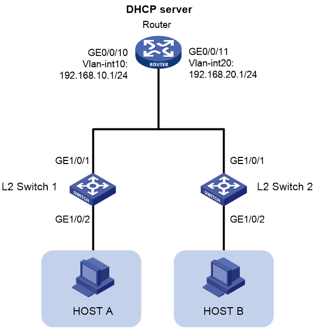
Network configuration
As shown in Figure 1, Switch 1 and Switch 2 are attached to Router, and Host A and Host B are connected to Switch 1 and Switch 2, respectively. Configure the network to meet the following requirements:
· Host A and Host B obtain IP addresses from the subnets of VLAN 10 and VLAN 20, respectively.
· The gateways for VLAN 10 and VLAN 20 are located on Router, which also acts as the DHCP server to allocate IP addresses to the hosts.
Data plan
Table 1 Subnet plan
|
Subnet |
Detailed data plan |
|
VLAN 10 |
· Subnet: 192.168.10.0/24 · Gateway: Router · Gateway interface IP address: 192.168.10.1/24 |
|
VLAN 20 |
· Subnet: 192.168.20.0/24 · Gateway: Router · Gateway interface IP address: 192.168.20.1/24 |
|
VLAN 1 (interconnect address between Router and Switch) |
· Subnet: 192.168.1.0/0 · Router interconnect interface IP address: 192.168.1.1/24 · Switch 1 interconnect interface IP address: 192.168.1.2/24 · Switch 2 interconnect interface IP address: 192.168.1.3/24. |
Table 2 VLAN assignment plan for interfaces
|
Device |
VLAN assignment plan for interfaces |
|
Router |
· Connect interface GE 0/0/10 to Switch 1. Configure the link type as trunk and PVID as 1, and assign the interface to VLAN 1 and VLAN 10. · Connect interface GE 0/0/11 to Switch 2. Configure the link type as trunk and PVID as 1, and assign the interface to VLAN 1 and VLAN 20. |
|
Switch 1 |
· Connect interface GE 1/0/1 to Router. Configure the link type as trunk and PVID as 1, and assign the interface to VLAN 1 and VLAN 10. · Connect interface GE1/0/2 to Host A. Configure the link type as access, and assign the interface to VLAN 10. |
|
Switch 2 |
· Connect interface GE 1/0/1 to Router. Configure the link type as trunk and PVID as 1, and assign the interface to VLAN 1 and VLAN 20. · Connect interface GE1/0/2 to Host B. Configure the link type as access, and assign the interface to VLAN 20. |
Analysis
· Configure subnets on Router and switches as planned, and configure the DHCP server on Router to assign IP addresses to endpoints.
Restrictions and guidelines
· The default IP address of VLAN-interface 1 on Router is 192.168.0.1/23. Edit the default IP address of VLAN-interface 1 on Router and switches as required.
· After editing the default IP address of VLAN-interface 1 on Router, use the new IP address to log in to the Web management interface.
Prerequisites
· Connect the PC to the LAN interface of Router by using an Ethernet cable. Configure the PC with a fixed IP address of 192.168.0.X/23. Then, open a browser and enter the management IP address of Router (https://192.168.0.1) to access the Web management interface.
· Verify that the PC has installed terminal software and is connected to a switch's Console port through a serial cable. Start the terminal software and configure the relevant parameters to connect to the backend interface of the switch.
Procedures
Configuring Router
1. Change the IP address of VLAN-interface 1 to 192.168.1.1/24 as required:
a. From the left navigation pane, select Network > LAN Settings.
b. Click the Edit icon in the Actions column for VLAN-interface 1 to access the page for editing the LAN settings.
c. In the Interface IP address field, change the IP address of the interface to 192.168.1.1.
d. In the Subnet Mask field, change the subnet mask to 255.255.255.0.
e. Clear the Enable DHCP option to disable DHCP.
f. Use the default settings for the other parameters, and then click Apply.
Figure 2 Editing the LAN

2. Create VLAN 10, configure an IP address for the VLAN interface, and enable DHCP on the interface:
a. From the left navigation pane, select Network > LAN Settings.
b. Click Add.
c. In the LAN interface type field, select VLAN interface.
d. In the VLAN ID field, enter 10.
e. In the Interface IP address field, enter 192.168.10.1.
f. In the Subnet Mask field, enter 255.255.255.0.
g. Select the Enable DHCP option to enable DHCP.
h. Use the default settings for the other parameters, and then click Apply.
Figure 3 Configuring VLAN 10

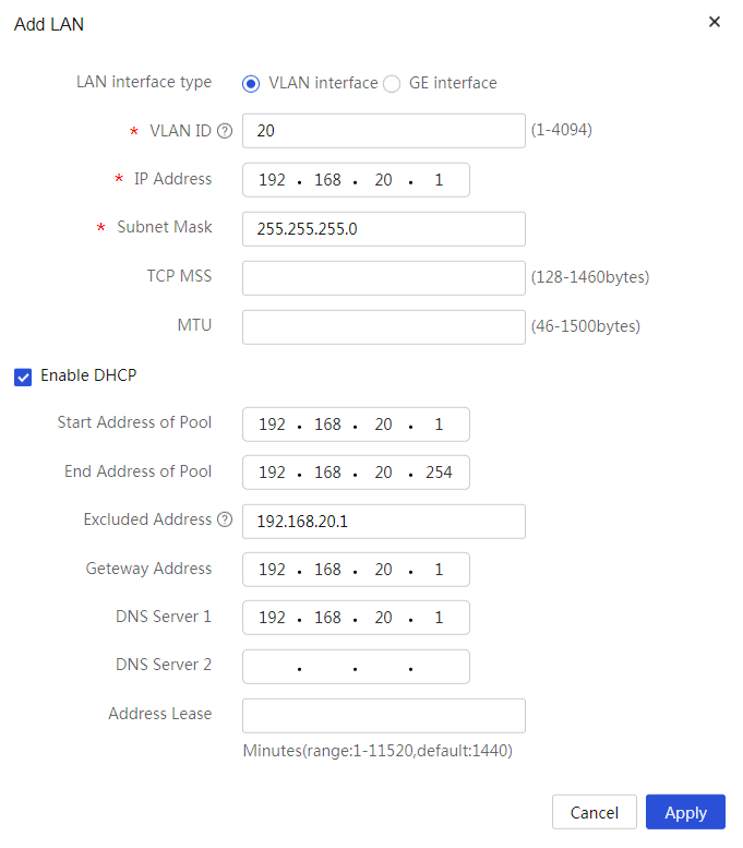
3. Create VLAN 20, configure an IP address for the VLAN interface, and enable DHCP on the interface:
a. From the left navigation pane, select Network > LAN Settings.
b. Click Add.
c. In the LAN interface type field, select VLAN interface.
d. In the VLAN ID field, enter 20.
e. In the Interface IP address field, enter 192.168.20.1.
f. In the Subnet Mask field, enter 255.255.255.0.
g. Select the Enable DHCP option to enable DHCP.
h. Use the default settings for the other parameters, and then click Apply.
Figure 4 Configuring VLAN 20
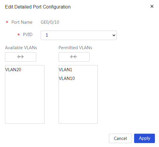
4. Assign interface GE 0/0/10 to VLAN 1 and VLAN 10:
a. From the left navigation pane, select Network > LAN Settings.
b. Click the VLAN Division tab.
c. Click the Edit icon in the Actions column for interface GE 0/0/10.
The detailed port configuration page opens.
d. Click VLAN 10 in the Available VLANs area to add VLAN 10 to the Selected VLANs area.
e. Use the default settings for the other parameters, and then click Apply.
Figure 5 Configuring interface GE 0/0/10
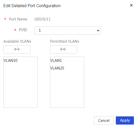
5. Assign interface GE 0/0/11 to VLAN 1 and VLAN 20:
a. From the left navigation pane, select Network > LAN Settings.
b. Click the VLAN Division tab.
c. Click the Edit icon in the Actions column for interface GE 0/0/11.
The detailed port configuration page opens.
d. Click VLAN 20 in the Available VLANs area to add VLAN 20 to the Selected VLANs area.
e. Use the default settings for the other parameters, and then click Apply.
Figure 6 Configuring interface GE 0/0/11
Configuring Switch 1
1. Configure the IP address for VLAN-interface 1 and configure VLAN 10.
<L2 switch 1> system-view
[L2 switch 1] interface vlan 1
[L2 switch 1-interface1] ip address 192.168.1.2 24
[L2 switch 1-interface1] quit
[L2 switch 1] VLAN 10
[L2 switch 1-VLAN10] quit
2. Set the link type of GigabitEthernet 1/0/1 to trunk and assign it to VLANs 1 and 10.
[L2 switch 1] interface gigabitethernet 1/0/1
[L2 switch 1-GigabitEthernet1/0/1] port link-type trunk
[L2 switch 1-GigabitEthernet1/0/1] port trunk permit VLAN 1 10
[L2 switch 1-GigabitEthernet1/0/1] quit
3. Set the link type of interface GigabitEthernet 1/0/2 to access and assign it to VLAN 10.
[L2 switch 1] interface gigabitethernet 1/0/2
[L2 switch 1-GigabitEthernet1/0/2] port link-type access
[L2 switch 1-GigabitEthernet1/0/2] port access vlan 10
[L2 switch 1-GigabitEthernet1/0/2] quit
[L2 switch 1]
Configuring Switch 2
1. Configure the IP address for VLAN-interface 1 and configure VLAN 20.
<L2 switch 2> system-view
[L2 switch 2] interface vlan 1
[L2 switch 2-interface1] ip address 192.168.1.3 24
[L2 switch 2-interface1] quit
[L2 switch 2] VLAN 20
[L2 switch 2-VLAN20] quit
2. Set the link type of GigabitEthernet 1/0/1 to trunk and assign it to VLANs 1 and 20.
[L2 switch 2] interface gigabitethernet 1/0/1
[L2 switch 2-GigabitEthernet1/0/1] port link-type trunk
[L2 switch 2-GigabitEthernet1/0/1] port trunk permit VLAN 1 20
[L2 switch 2-GigabitEthernet1/0/1] quit
3. Set the link type to access for interface GigabitEthernet 1/0/2 and assign it to VLAN 20.
[L2 switch 2] interface gigabitethernet 1/0/2
[L2 switch 2-GigabitEthernet1/0/2] port link-type access
[L2 switch 2-GigabitEthernet1/0/2] port access vlan 20
[L2 switch 2-GigabitEthernet1/0/2] quit
Verifying the configuration
Host A can obtain an IP address from the subnet of VLAN 10, and Host B can obtain an IP address from the subnet of VLAN 20. Verify that the configuration is successful.