- Table of Contents
- Related Documents
-
| Title | Size | Download |
|---|---|---|
| 01-Policy-Based Routing Configuration Examples | 168.29 KB |
Introduction
The following information provides an example for configuring policy-based routing (PBR).
You can configure PBR to forward traffic from specific LAN hosts through designated WAN interfaces within a certain time period.
Prerequisites
This document is not restricted to specific software or hardware versions. Procedures and information in the examples might be slightly different depending on the software or hardware version of the router.
The configuration examples were created and verified in a lab environment, and all the devices were started with the factory default configuration. When you are working on a live network, make sure you understand the potential impact of every command on your network.
The following information is provided based on the assumption that you have basic knowledge of PBR.
Software versions used
This configuration example was created and verified on Release 9141P22 of the SR6602-IE router.
Example: Configuring PBR
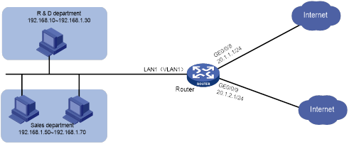
Network configuration
As shown in Figure 1, Router serves as the enterprise's egress gateway and connects to the Internet through interfaces GE0/0/8 and GE0/0/9, whose connection mode is fixed address. The IP address of WAN0 is 20.1.1.1/24, and its gateway address is 20.1.1.254.
The IP address of is 20.1.2.1/24, and its gateway address is 20.1.2.254.
To separate service traffic during work hours (8:30-18:00 on Monday to Friday), configure the router to meet the following requirements:
· The router forwards network access traffic from the R & D department through interface WAN0.
· The router forwards network access traffic from the sales department through interface WAN1.
Procedure
Configuring Internet access settings for the router
# Navigate to the Network Settings > External Networks page to access the external network configuration page.
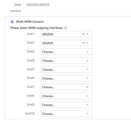
1. On the Scene page, select the multi-WAN scenario.
2. Select GE0/0/8 for Line1.
3. Select GE0/0/9 for Line2.
4. Click Apply.
Figure 2 Scenario settings
5. Click the WAN Settings tab to access the WAN configuration page.
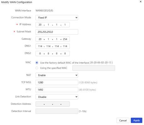
6. Click the Edit icon in the Actions column for WAN8(GE0/0/8) to access the WAN configuration modification page.
7. Select Fixed IP for Connection Mode.
8. Enter 20.1.1.1 for IP Address.
9. Enter 255.255.255.0 for Subnet Mask.
10. Enter 20.1.1.254 for Gateway.
11. Enter the primary DNS server address 114.114.114.114 and backup DNS server address 8.8.8.8 for DNS1 and DNS2, respectively.
12. Select Enable for NAT.
13. Use default settings for other parameters, and then click Apply.
Figure 3 Configuring Internet access settings for WAN8
14. Click the Edit icon in the Actions column for WAN9(GE0/0/9) to enter the WAN configuration modification page.
15. Select Fixed IP for Connection Mode.
16. Enter 20.1.2.1 for IP Address.
17. Enter 255.255.255.0 for Subnet Mask.
18. Enter 20.1.2.254 for Gateway.
19. Enter the primary DNS server address 114.114.114.114 and backup DNS server address 8.8.8.8 for DNS1 and DNS2, respectively.
20. Select Enable for NAT.
21. Use default settings for other parameters, and then click Apply.
Configure PBR
Configuring PBR policy settings for the R & D department
1. Navigate to the Advanced Settings > Policy-Based Routing page.
2. Click Add.
3. Select IP for Protocol Type.
4. Enter 192.168.1.10-192.168.1.30 for Source Address Range.
5. Enter 0.0.0.0-255.255.255.0 (all addresses) for Destination Address Range.
6. Specify 08:00 to 18:00 from Monday to Friday for Valid Period.
7. Select WAN8(GE0/0/8) for Output Interface, and enter IP address 20.1.1.254 of interface WAN0 for Next Hop
8. Use default settings for other parameters, and then click Apply.
Figure 4 Configuring PBR policy settings for the sales department

Configuring PBR policy settings for the sales department
1. Navigate to the Advanced Settings > Policy-Based Routing page.
2. Click Add.
3. Select IP for Protocol Type.
4. Enter 192.168.1.50-192.168.1.70 for Source Address Range.
5. Enter 0.0.0.0-255.255.255.0 (all addresses) for Destination Address Range.
6. Specify 08:00 to 18:00 from Monday to Friday for Valid Period.
7. Select WAN9(GE0/0/9) for Output Interface, and enter IP address 20.1.2.254 of interface WAN1 for Next Hop
8. Use default settings for other parameters, and then click Apply.
Verifying the configuration
1. Log in to the Web interface on the PC of an R & D department employee, perform a tracert operation to target IP address 200.1.1.1, and view the routing path.
C:\Users\abc>tracert 200.1.1.1
Tracing route to 200.1.1.1 over a maximum of 30 hops:
1 <1 ms 1 ms 1 ms erlogin.cn[192.168.1.1]
2 <1 ms <1 ms <1 20.1.1.254
3 <1 ms <1 ms <1 200.1.1.1
Trace complete.
2. Log in to the Web interface on the PC of a sales department employee, perform a tracert operation to target IP address 200.1.1.1, and view the routing path.
C:\Users\cbd>tracert 200.1.1.1
Tracing route to 200.1.1.1 over a maximum of 30 hops:
1 <1 ms 1 ms 1 ms erlogin.cn[192.168.1.1]
2 <1 ms <1 ms <1 20.1.2.254
3 <1 ms <1 ms <1 200.1.1.1
Trace complete.
The routing paths show that R & D department accesses the Internet through the gateway of WAN8(GE0/0/8), and the sales department accesses the Internet through the gateway of WAN9(GE0/0/9). The PBR policy is configured successfully.
