- Table of Contents
- Related Documents
-
| Title | Size | Download |
|---|---|---|
| 06-MAP-E configuration | 246.73 KB |
Contents
Configuring the DHCPv6 client to obtain MAP-E information
Enabling anti-spoofing for MAP-E tunnel packets
Verifying and maintaining MAP-E
Example: Configuring basic MAP-E
Configuring MAP
About MAP
Mapping of Address and Port (MAP) is an IPv4-to-IPv6 transition technique, which allows carriers to carry IPv4 services in a pure IPv6 network. Integrating with stateless and dual translation and encapsulation techniques, MAP can map IPv4 packets to IPv6 packets statelessly.
The MAP technique contains the following types based on the IPv4 packet encapsulation method: Mapping of Address and Port with Encapsulation (MAP-E) and Mapping of Address and Port using Translation (MAP-T). Both MAP-E and MAP-T are IPv4-over-IPv6 IPv6 transition techniques. Only MAP-E is supported in the current software version.
In an IPv4-over-IPv6 scenario, MAP has significant advantages over performance, availability, and deployment costs and effectively reduces device investment costs for carriers. It also promotes the evolution of the network towards IPv6.
Basic concepts
The following describes basic concepts for MAP:
· MAP-E—A stateless transition technique that encapsulates IPv4 packets with an IPv6 packet header.
· MAP Customer Edge (CE)—A device located between the IPv4 network and the IPv6 network.
· MAP Border Relay (BR)—A device located at the border of the IPv6 network and the IPv4 network.
· MAP rule—Describes the mapping between an IPv4 prefix (network number of an IPv4 address), dedicated IPv4 address, or shared IPv4 address and an IPv6 prefix or address. MAP rules include BMRs and FMRs.
· MAP domain—Consists of multiple CEs and BRs. In the same MAP domain, the MAP CEs and MAP BRs share the same IPv6 prefix, IPv4 prefix, address translation rule, and forwarding rule.
· Port set—A port group which has a range of consecutive port numbers. Numbers of ports in different port groups are independent of each other. Different MAP CEs have different port groups.
· Port Set ID (PSID)—The length (k) of a PSID determines the sharing ratio (R), which equals to 2k. Transport layer ports are divided into 2k sets and each set contains a group of consecutive port numbers. Each set is used by a MAP CE.
· Shared IPv4 address—An IPv4 address shared among multiple CEs. A CE can use only ports in a port set to communicate with other devices. Shared IPv4 addresses are also known as port-restricted IPv4 addresses.
· End-user IPv6 prefix—IPv6 prefix assigned to the MAP CE through DHCPv6. The End-user IPv6 prefix of a MAP CE is unique.
· MAP IPv6 address—IPv6 address of a CE enabled with MAP, which is used to reach the CE from the BR or other CEs.
· Rule IPv6 prefix—IPv6 prefix and length specified by the MAP rule.
· Rule IPv4 prefix—IPv4 prefix and length specified by the MAP rule. The IPv4 prefix and length represent the network number and mask length of an IPv4 address, respectively.
· Embedded Address bits (EA-bits)—Indicates the total length of the IPv4 suffix and the PSID in the IPv6 prefix assigned to a CE.
Basic architecture
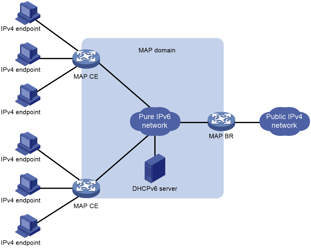
As shown in Figure 1, the network deployed with MAP-E has MAP CEs and a MAP BR. MAP CEs serve as the service access points for private IPv4 users and the MAP BR acts as the edge node between the IPv4 network and the IPv6 network. The MAP CEs and MAP BR make up a MAP domain. In the same MAP domain, the MAP CEs and MAP BR share the same IPv6 prefix, IPv4 prefix, BMR, and FMR.
|
|
IMPORTANT: · H3C devices can only operate as MAP CEs. · A MAP domain can have only one MAP BR. |
Operating mechanism
1. A MAP CE, acting as a DHCPv6 client, sends a DHCPv6 request to the DHCPv6 server for the End-user IPv6 prefix and MAP-E information. The request contains Option Request Option (Option 6), which is used to request from the DHCPv6 server for Option 94 that contains MAP-E information.
Option 94 in the response sent by the DHCPv6 server issues MAP-E information through the following sub-options. Option 89 and Option 93 make up a BMR.
¡ Option 89 contains the EA-bits, IPv4 prefix, IPv4 prefix length, IPv6 prefix, and IPv6 prefix length.
¡ Option 93 contains the value, length, and offset bits of a PSID.
¡ Option 90 contains the IPv6 address of the MAP BR.
Public resources include public IPv4 address and port information. The MAP CE can directly obtain the public IPv4 address information from the MAP-E information. At the same time, the MAP CE calculates the post sets based on the value, length, and offset bits of the PSID.
4. The tunnel module of the MAP CE encapsulates the original IPv4 packet with an IPv6 packet header, in which the source IPv6 address is obtained in step 3, and the destination IPv6 address is the IPv6 address of the BR. Then, the MAP CE sends the encapsulated packet to the MAP BR through the IPv6 network.
5. Upon receiving the packet, the MAP BR checks the source IPv6 address and source port. If the IPv6 packet passes the check, the MAP BR removes the IPv6 packet header to obtain the original IPv4 packet, and then forwards the IPv4 packet based on the route.
If the IPv6 packet fails the check, the MAP BR discards the IPv6 packet.
Packet processing flow
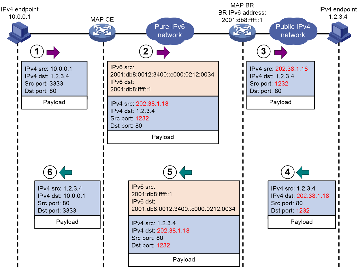
Figure 2 shows the packet processing flow of MAP-E.
1. A private IPv4 user sends a packet to a public IPv4 user.
2. After the MAP CE receives the packet, the NAT and tunnel modules of the MAP CE perform the following tasks:
a. The NAT module translates the private source IP address and source port number in the IPv4 packet to a public address and port number.
b. The tunnel module calculates the IPv6 address corresponding to the public source IPv4 address and source port number based on the BMR. Then, it encapsulates the IPv4 packet with an IPv6 packet header, in which the source IPv6 address is the calculated IPv6 address and the destination IPv6 address is the IPv6 address of the BR.
3. After the MAP BR receives the IPv6 packet, the tunnel module checks the source IPv6 address and port in the packet. If the packet passes the check, the tunnel module removes the IPv6 packet header to obtain the original IPv4 packet. Then, the forwarding module forwards the IPv4 packet to the public IPv4 network side based on an IPv4 route.
4. The public IPv4 user sends a response to the private IPv4 network side.
5. After the MAP BR receives the IPv4 packet, the tunnel module calculates the IPv6 address corresponding to the destination IPv4 address and destination port number based on the BMR. Then, it encapsulates the IPv4 packet with an IPv6 packet header, in which the destination IPv6 address and source IPv6 address are the calculated IPv6 address and IPv6 address of the MAP BR, respectively.
6. After the MAP CE receives the IPv6 packet, the tunnel module removes the IPv6 packet header to obtain the original IPv4 packet. The NAT module looks up the address mapping table and translates the destination IP address and destination port number in the IPv4 packet. Then, the forwarding module forwards the IPv4 packet to the private IPv4 network side based on an IPv4 route.
Figure 2 Packet processing flow for MAP-E
Mapping rule
Port number mapping
Upon receiving a private IPv4 packet, the MAP CE translates the source IPv4 address and source port of the packet. Then, the tunnel module of the MAP CE encapsulates the translated IPv4 packet with an IPv6 header. To improve public IPv4 address usage, MAP uses transport layer ports to extend IPv4 addresses. As a result, a public IPv4 address on the MAP CE can be used by multiple private users.
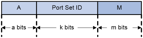
MAP divides a 16-bit transport layer port number into the following parts:
· A—PSID offset, which is the number of PSID offset bits. The default value is 6. The PSID offset avoids conflicts with well-known port numbers in the range of 0 to 1023.
· PSID—The length (k) of a PSID determines the sharing ratio (R), which equals to 2k. Transport layer ports are divided into 2k sets and each set contains a group of consecutive port numbers. Each MAP CE has a unique port set.
· M—The length (m) of this field determines the number of consecutive ports in the port set, which is 2m.
Consequently, a total of 2k port sets are obtained. A PSID uniquely identifies a port set. Each port set contains a number of ((2A)-1)×(2m) ports.
Figure 3 Transport layer port structure for MAP
For example, the PSID offset is 4, the PSID length is 10, and the length of the M field is 2. The transport layer ports are divided into 210=1024 port sets. Each port set contains ((24)-1)*(22)=60 port numbers. Table 1 shows the mappings between PSID values and port sets. The port sets in the table are segmented because the port numbers in the port sets are not consecutive.
Table 1 Mappings between PSID values and port sets
|
PSID value |
First range of consecutive port numbers in the port set (A=0001) |
Second range of consecutive port numbers in the port set (A=0010) |
… |
Fifteenth range of consecutive port numbers in the port set (A=1111) |
|
0 |
4096, 4097, 4098, 4099 |
8192, 8193, 8194, 8195 |
… |
61440, 61441, 61442, 61443 |
|
1 |
4100, 4101, 4102, 4103 |
8196, 8197, 8198, 8199 |
… |
61444, 61445, 61446, 61447 |
|
2 |
4104, 4105, 4106, 4107 |
8200, 8201, 8202, 8203 |
… |
61448, 61449, 61450, 61451 |
|
3 |
4108, 4109, 4110, 4111 |
8204, 8205, 8206, 8207 |
… |
61452, 61453, 61454, 61455 |
|
… |
… |
… |
… |
… |
|
1023 |
8188,8189,8190,8191 |
12284,12285,12286,12287 |
… |
65532, 65533, 65534, 65535 |
Address mapping mechanism
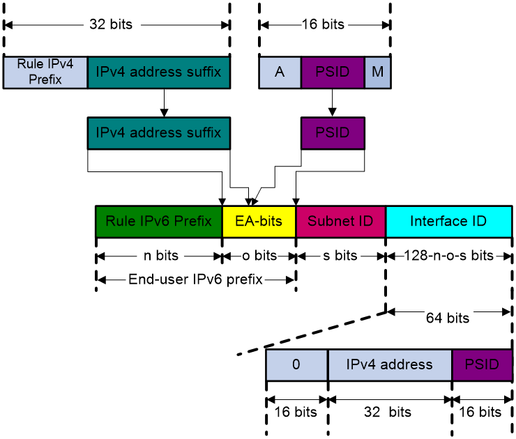
The MAP CE maps the translated IPv4 address and port number of the original IPv4 packet to an IPv6 address based on the mapping rule, as shown in Figure 4. The IPv6 address contains the Rule IPv6 prefix, EA, Subnet ID, and Interface ID fields. The mapping rule establishes a strong connection between the IPv4 address and port information and the IPv6 address to perform a stateless mapping. This protects the MAP BR from maintaining the mapping between the IPv6 and IPv4 addresses.
· Rule IPv6 prefix—IPv6 prefix assigned to the MAP CE by the DHCPv6 server.
· Subnet ID—ID of the first subnet. The value for s is 0.
· EA—A combination of the IPv4 suffix and the value of the transport layer port's PSID.
· Interface ID—A combination of an IPv4 address and PSID value.
¡ IPv4 address—If the DHCPv6 server assigns a shared IPv4 address or a dedicated IPv4 address to the MAP CE, the value is the assigned 32-bit IPv4 address. If the DHCPv6 server assigns a Rule IPv4 prefix to the MAP CE, the value for this field is right-padded with 0s to create a 32-bit field. For example, if the Rule IPv4 prefix is 2.1.1.0/29, the value for this field is 0x02010100 (hexadecimal).
¡ PSID—If the PSID value extracted from the EA-bits is less than 16 bits, it is left-padded with 0s to create a 16-bit field. For example, if the PSID value extracted from the EA-bits is 0xAC, the value for this field is 0x00AC. If the DHCPv6 server assigns a Rule IPv4 prefix or a dedicated IPv4 address, no PSID value can be extracted. The value for this field is 0x0000.
Figure 4 Mapping between an IPv4 address and an IPv6 address
MAP rules
MAP-E rules contain BMRs and FMRs. BMRs are required and FMRs are optional.
· BMR—Describes the mapping between an IPv6 address and an IPv4 address+port. A MAP CE uses a BMR to perform NAT44 on IPv4 packets and encapsulates the translated IPv4 packets with an IPv6 packet header. A MAP BR uses a BMR to decapsulate IPv6 packets and encapsulate the returned packets with an IPv6 packet header, and then forwards the packets to MAP CEs based on an IPv6 route in the MAP domain.
· FMR—Used to implement direct communication between MAP CEs in a MAP domain without MAP BRs. In a MAP domain, when a MAP CE accesses another MAP CE, the source IPv6 address is the IPv6 address calculated by the MAP CE through BMR, and the destination IPv6 address is the address of the peer MAP CE. An FMR is used by the MAP CE to calculate the IPv6 address of the peer MAP CE, which is used as the destination IPv6 address. At present, the FMR must be the same as the BMR.
As shown in Figure 5, MAP CE 1, MAP CE 2, and MAP BR reside in the same MAP domain. MAP CE 1 and MAP CE 2 have the same BMR and the FMR is the same as the BMR.
Figure 5 Accessing MAP CE 1 from MAP CE 2 by using an FMR
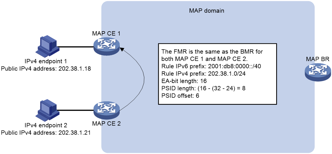
When IPv4 endpoint 2 accesses IPv4 endpoint 1 by using the public IPv4 address and port number of IPv4 endpoint 1, MAP CE 2 encapsulates the original IPv4 packet sent by IPv4 endpoint 2 with an IPv6 header as follows:
2. MAP CE 2 calculates the IPv6 address of IPv4 endpoint 1 based on the public IPv4 address and port number information of IPv4 endpoint 1 and the FMR.
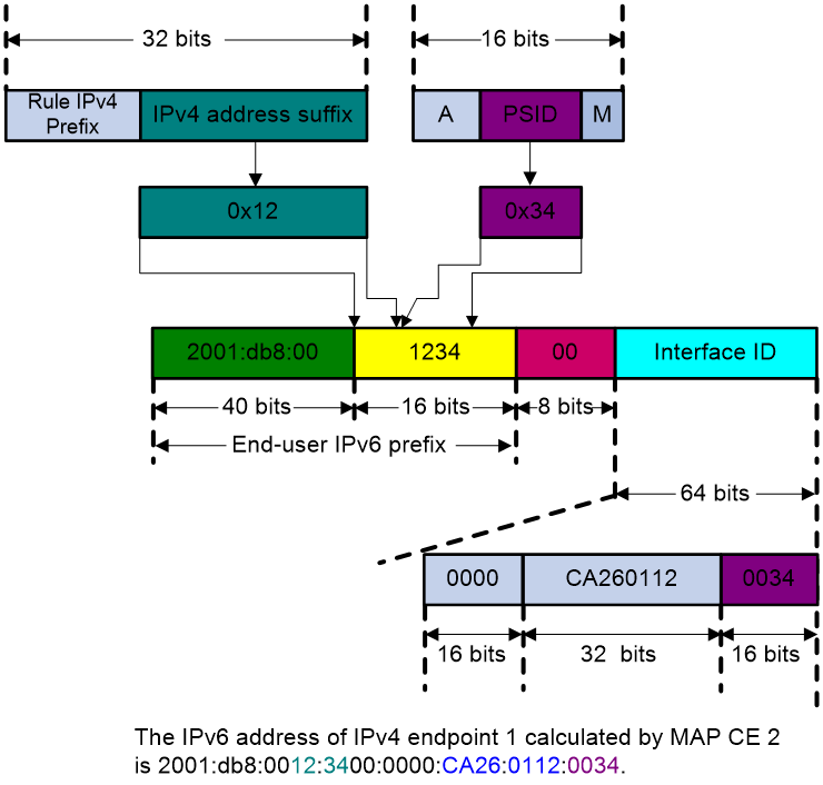
Figure 6 shows the calculation process.
Figure 6 Calculating the IPv6 address of IPv4 endpoint 1
3. MAP-CE 2 encapsulates the original IPv4 packet sent by IPv4 endpoint 2 with an IPv6 packet header. The source IPv6 address and destination IPv6 address in the IPv6 packet header are the IPv6 addresses obtained from steps 1 and 2, respectively.
MAP CE 2 does not send the packet to the MAP BR because the destination IPv6 address in the IPv6 packet header is the IPv6 address of IPv4 endpoint 1.
Similarly, when MAP CE 1 returns a response to MAP CE 2, it also encapsulates the original packet with an IPv6 packet header.
Obtaining MAP-E information
Methods of obtaining MAP-E information
The MAP CE, working as a DHCPv6 client, can use one of the following methods to obtain MAP-E information:
· DHCPv6—Stateful. The DHCPv6 client sends a DHCPv6 request to the DHCPv6 server for prefix and MAP-E information.
· NDRA—Stateless. The DHCPv6 client automatically obtains a prefix from a ND RA message based on the neighbor discovery protocol, and then sends an Information-request packet to the DHCPv6 server for MAP-E information.
After you bind a MAP-E instance to a physical interface on the MAP CE and specify a MAP-E information obtaining method, the DHCPv6 requests or Information-request packets sent to the DHCPv6 server carry Option Request Option (Option 6). Option 6 is used to request from the DHCPv6 server for Option 94. Upon receiving such packets, the DHCPv6 server sends responses that carry Option 94 to issue MAP-E information. Option 94 contains sub-options Option 89, Option 93, and Option 90. Option 89 and Option 93 make up a BMR, and Option 90 provides the IPv6 address of the MAP BR.
MAP-E option encapsulation
After the MAP CE requests MAP-E information from the DHCPv6 server, it obtains MAP-E information by resolving Option 94 carried in the DHCPv6 response.
· Option 94
Option 94, also known as MAP-E Container Option, carries only MAP-E information. Figure 7 shows the format of Option 94.
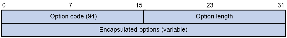
¡ Option code—Option number, which is 94.
¡ Option length—Length of the option, variable.
¡ Encapsulated-options—Sub-options encapsulated in Option 94, including Option 89, Option 90, and Option 93.
· Option 89
Option 89, also known as MAP-E Rule Option, is required for Option 94. Figure 8 shows the format of Option 89.
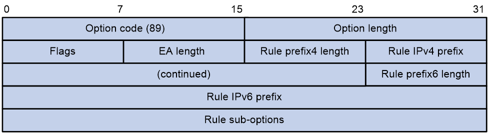
¡ Option code—Option number, which is 89.
¡ Option length—Length of the option, variable.
¡ Flags—Rule identifier.
- The reserved bit is fixed at 0 at present.
- The F bit identifies the rule type. Value 1 indicates a BMR and value 0 indicates an FMR.
¡ EA length—Length of the EA-bits.
¡ Rule prefix4 length—IPv4 prefix length.
|
|
NOTE: The EA length and Rule prefix4 length fields jointly determine the type of IP address assigned to the MAP CE. · When EA length+Rule prefix4 length<32, the DHCPv6 server assigns an IPv4 prefix (IP address segment) to the CE. · When EA length+Rule prefix4 length=32, the DHCPv6 server assigns a dedicated IP address to the CE. · When EA length+Rule prefix4 length>32, the DHCPv6 server assigns a shared IP address to the CE. |
¡ Rule IPv4 prefix—IPv4 prefix.
¡ Rule prefix6 length—IPv6 prefix length.
¡ Rule IPv6 prefix—IPv6 prefix.
¡ Rule sub-options—Sub-option of the rule, which is Option 93.
· Option 90
Option 90, also known as BR Option, is required for Option 94. Figure 9 shows the format of Option 90.
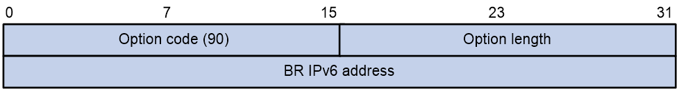
¡ Option code—Option number, which is 90.
¡ Option length—Length of the option, which is 16 bytes.
¡ BR IPv6 address—IPv6 address of the BR.
· Option 93
Option 93, also known as Port Parameters Option, is required for Option 89. Figure 10 shows the format of Option 93.
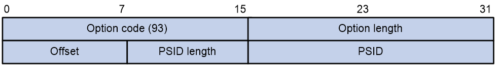
¡ PSID Offset—Offset bits of the PSID.
¡ PSID Len—Length of the PSID.
¡ PSID—PSID value.
Whether the response sent from the DHCPv6 server to the MAP CE carries Option 93 affects the value padded to the PSID field by the MAP CE, as shown in Table 2.
Table 2 Methods of padding the PSID field by the MAP CE
|
Whether the response carries Option 93 |
PSID field padding method |
|
Yes |
· If the DHCPv6 server assigns an IPv4 prefix or dedicated IPv4 address to the MAP CE, the field is padded with all 0s. · If the DHCPv6 server assigns a shared IPv4 address to the MAP CE, the field is the PSID value carried in Option 93. |
|
No |
· If the DHCPv6 server assigns an IPv4 prefix or a dedicated IPv4 address to the MAP CE, the field is padded with all 0s. · If the DHCPv6 server assigns a shared IPv4 address to the MAP CE, the MAP CE calculates the PSID value as follows and pad the field with the value: a. Calculates the PSID length based on the information in Option 89. b. Calculates the M field length based on default value of the PSID Offset field 6. c. Calculates the PSID value based on the PSID offset bits, PSID length, and M field length. |
Protocols and standards
· RFC 7597, Mapping of Address and Port with Encapsulation (MAP-E)
· RFC 7598, DHCPv6 Options for Configuration of Softwire Address and Port-Mapped Clients
MAP-E tasks at a glance
To configure MAP-E, perform the following tasks on the MAP CE:
· Configuring the DHCPv6 client to obtain MAP-E information
· (Optional.) Enabling anti-spoofing for MAP-E tunnel packets
Prerequisites for MAP-E
Perform the following tasks before you configure MAP-E:
· On the DHCPv6 server, configure settings related to issuing MAP-E information.
· On the MAP BR, configure the BMR.
· On the MAP CE, configure the following settings:
¡ Configure the DHCPv6 client feature. The DHCPv6 client can obtain a prefix through DHCPv6 or NDRA. For more information about obtaining a prefix through DHCPv6, see DHCPv6 configuration in Layer 3—IP Services Configuration Guide. For more information about obtaining a prefix through NDRA, see IPv6 basics configuration in Layer 3—IP Services Configuration Guide.
¡ For how to create a MAP-E tunnel interface, see tunnel interface configuration in Interface Configuration Guide.
Configuring the DHCPv6 client to obtain MAP-E information
About this task
When the MAP CE works as a DHCPv6 client, it can use one of the following methods to obtain MAP-E information:
· DHCPv6—Stateful. The DHCPv6 client sends a DHCPv6 request to the DHCPv6 server for End-user IPv6 prefix and MAP-E information.
· NDRA—Stateless. The DHCPv6 client automatically obtains a prefix from a ND RA message based on the neighbor discovery protocol, and then sends an Information-request packet to the DHCPv6 server for MAP-E information.
After the DHCPv6 module obtains MAP-E information, it pushes the MAP-E information to the NAT and tunnel modules through a MAP-E instance. The NAT and tunnel modules use the MAP-E rule to perform address translation and packet encapsulation.
The MAP-E instance is bound to the physical interface that receives DHCPv6 replies so that it carries the MAP-E information in the DHCPv6 replies.
The MAP-E instance is bound to a MAP-E tunnel interface and pushes the MAP-E information to the NAT and tunnel modules through the MAP-E tunnel interface.
Restrictions and guidelines
You can bind a MAP-E instance to only one physical interface and bind only one MAP instance to the same physical interface.
You can bind a MAP-E instance to only one tunnel interface and bind only one MAP instance to the same tunnel interface.
You can bind only created MAP-E instances to MAP-E tunnel interfaces. You cannot delete MAP-E instances that are bound to MAP-E tunnel interfaces. To delete such MAP-E instances, first delete the MAP-E tunnel interfaces to which the MAP-E instances are bound.
Procedure
1. Enter system view.
system-view
2. Create a MAP-E instance and enter its view.
map-e instance instance-name dynamic
3. Specify a method for the MAP-E instance to obtain MAP-E information.
mode { ndra | pd }
By default, MAP-E instances obtain MAP-E information through DHCPv6.
4. Bind a MAP-E instance to a physical interface.
source interface interface-type interface-number
By default, a MAP-E instance is not bound to any physical interface.
5. Return to system view.
quit
6. Create a MAP-E tunnel interface and enter its view.
interface tunnel number mode map-e
7. Bind the MAP-E instance to a MAP-E tunnel interface.
map-e instance instance-name
By default, no MAP-E instances are bound to a MAP-E tunnel interface.
Enabling NAT MAP
About this task
Enabled with this feature, the MAP CE uses the public IPv4 addresses and port sets issued by the DHCPv6 server through Option 94 to perform an IPv4 address+port translation on the received private IPv4 packets.
Restrictions and guidelines
You can enable this feature only on MAP-E tunnel interfaces.
Procedure
1. Enter system view.
system-view
2. Create a MAP-E tunnel interface and enter its view.
interface tunnel number mode map-e
3. Enable NAT MAP.
nat map enable
By default, NAT MAP is disabled.
Enabling anti-spoofing for MAP-E tunnel packets
About this task
After receiving an IPv6 packet from the peer end, the MAP-E tunnel interface enabled with this feature on the MAP CE first checks packet validity, and then decapsulates the packet if it passes the check. The packet check rule is as follows:
· If the outer source IPv6 address is the IPv6 address of the MAP BR, the packet passes the check.
· If the outer source IPv6 address is not the IPv6 address of the MAP BR, the MAP-E module calculates an IPv6 address by using the BMR rule based on the inner source IPv4 address of the packet. Then, it matches the calculated IPv6 address against the outer source IPv6 address of the packet. If the calculated IPv6 address does not match the outer source IPv6 address, the MAP-E module drops the packet to avoid spoofing attacks.
Restrictions and guidelines
Disable this feature on the local MAP-E tunnel interface when the peer MAP BR is a third-party device that does not support this feature.
Procedure
1. Enter system view.
system-view
2. Create a MAP-E tunnel interface and enter its view.
interface tunnel number mode map-e
3. Enable anti-spoofing for MAP-E tunnel packets.
map-e spoofing-enable
By default, anti-spoofing is enabled for MAP-E tunnel packets.
Verifying and maintaining MAP-E
Perform display tasks in in any view.
· Display public resources obtained in MAP-E information on MAP-E tunnel interfaces. The MAP-E information is notified by the MAP CE to the NAT module through the DHCPv6 server.
display nat map interface tunnel [ number ]
· Display MAP instance information.
display map instance [ name instance-name ] [ verbose ]
MAP-E configuration examples
Example: Configuring basic MAP-E
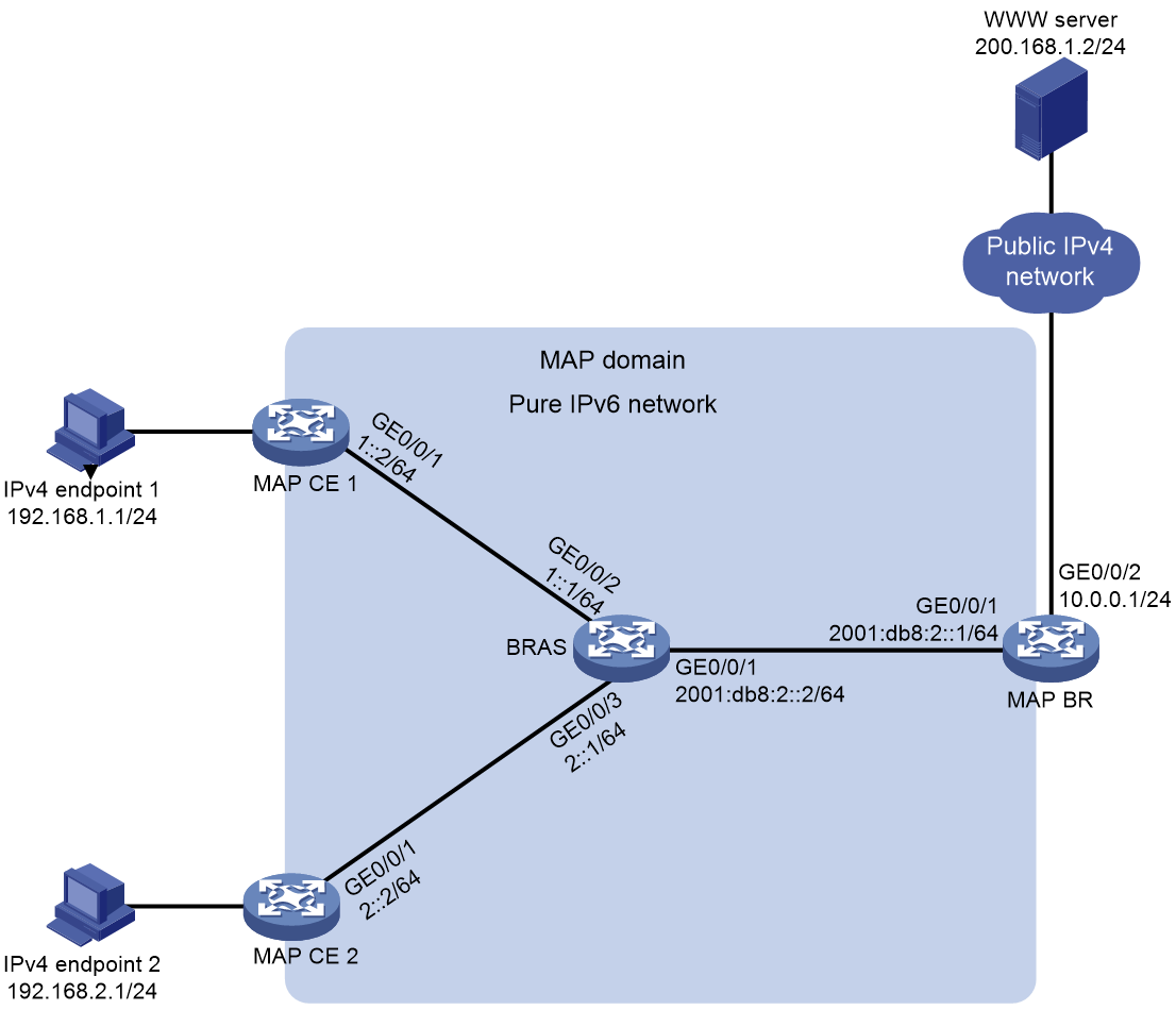
Network configuration
As shown in Figure 11, the MAP CEs connect to the MAP BR through the IPv6 access network, and the MAP BR connects to both the public IPv4 network and the IPv6 access network. The BRAS device, working as a DHCPv6 server, issues the BR IPv6 address and MAP rule to the MAP CEs. Each IPv4 endpoint connects to a MAP CE that performs packet encapsulation and accesses the public IPv4 network resources on subnet 10.0.0.1/24 through the MAP domain or the other IPv4 endpoint in the MAP domain.
The MAP-E information issued by the BRAS device is as follows:
· In the BMR, the Rule IPv6 Prefix is 2001:DB8:1:64BE::/64, the Rule IPv4 Prefix is 192.0.0.0/24, and the EA length is 16.
· The BR IPv6 address is 2001:DB8:CAFE::1.
Prerequisites
On the BRAS device, configure the settings related to issuing MAP-E information. On the MAP BR, configure the BMR.
Procedure
1. Configure MAP CE 1.
# Create a tunnel interface in MAP-E tunnel mode.
<MAP CE 1> system-view
[MAP CE 1] interface tunnel 1 mode map-e
[MAP CE 1-Tunnel1] quit
# Create MAP-E instance 1.
[MAP CE 1] map-e instance 1 dynamic
# Configure the MAP-E instance to obtain MAP-E information through DHCPv6.
[MAP CE 1-mape-1] mode pd
# Bind the MAP-E instance to physical interface GigabitEthernet 0/0/1. When the interface receives a response from the DHCPv6 server, the MAP CE associates the MAP-E information in the response with the MAP-E instance bound to the interface.
[MAP CE 1-mape-1] source interface gigabitethernet 0/0/1
[MAP CE 1-mape-1] quit
# Specify IPv6 address 1::2/64 for GigabitEthernet 0/0/1. Configure the interface as a DHCPv6 client for IPv6 prefix acquisition. Configure the DHCPv6 client to assign an ID to the obtained IPv6 prefix.
[MAP CE 1] interface gigabitethernet 0/0/1
[MAP CE 1-GigabitEthernet0/0/1] ipv6 address 1::2 64
[MAP CE 1-GigabitEthernet0/0/1] ipv6 dhcp client pd 1
[MAP CE 1-GigabitEthernet0/0/1] quit
# Bind MAP-E instance 1 to the tunnel interface, so that the DHCPv6 module of the MAP CE can push the obtained MAP-E information to the NAT and tunnel modules.
[MAP CE 1] interface tunnel 1
[MAP CE 1-Tunnel1] map-e instance 1
# Enable NAT MAP.
[MAP CE 1-Tunnel1] nat map enable
[MAP CE 1-Tunnel1] quit
# Configure a static route in which the destination address is 10.0.0.1/24 and output interface is the tunnel interface.
[MAP CE 1] ip route-static 10.0.0.1 24 tunnel 1
# Configure a static route in which the destination address is 192.168.2.1/24 and output interface is the tunnel interface.
[MAP CE 1] ip route-static 192.168.2.1 24 tunnel 1
# Configure a static route in which the destination address is the BR IPv6 address, output interface is GigabitEthernet 0/0/1, and next hop is 1::1.
[MAP CE 1] ipv6 route-static 2001:db8:cafe::1 128 gigabitethernet 0/0/1 1::1
# Specify slot 2 to process NAT traffic.
|
|
IMPORTANT: When private-to-public and public-to-private traffic of a session resides on different slots, you must use the nat service command to make sure address translation for the forward and reverse traffic are performed on the same NAT service card. |
[MAP CE 1] interface gigabitethernet 0/0/1
[MAP CE 1-GigabitEthernet0/0/1] nat service slot 2
[MAP CE 1-GigabitEthernet0/0/1] quit
# Configure the Endpoint-Independent Mapping mode for PAT.
[MAP CE 1] nat mapping-behavior endpoint-independent
2. Configure MAP CE 2.
# Create a tunnel interface in MAP-E tunnel mode.
<MAP CE 2> system-view
[MAP CE 2] interface tunnel 1 mode map-e
[MAP CE 2-Tunnel1] quit
# Create MAP-E instance 1.
[MAP CE 2] map-e instance 1 dynamic
# Configure the MAP-E instance to obtain MAP-E information through DHCPv6.
[MAP CE 2-mape-1] mode pd
# Bind the MAP-E instance to physical interface GigabitEthernet 0/0/1. When the interface receives a response from the DHCPv6 server, the MAP CE associates the MAP-E information in the response with the MAP-E instance bound to the interface.
[MAP CE 2-mape-1] source interface gigabitethernet 0/0/1
[MAP CE 2-mape-1] quit
# Specify IPv6 address 2::2/64 for GigabitEthernet 0/0/1. Configure the interface as a DHCPv6 client for IPv6 prefix acquisition. Configure the DHCPv6 client to assign an ID to the obtained IPv6 prefix.
[MAP CE 2] interface gigabitethernet 0/0/1
[MAP CE 2-GigabitEthernet0/0/1] ipv6 address 2::2 64
[MAP CE 2-GigabitEthernet0/0/1] ipv6 dhcp client pd 1
[MAP CE 2-GigabitEthernet0/0/1] quit
# Bind MAP-E instance 1 to the tunnel interface, so that the DHCPv6 module of the MAP CE can push the obtained MAP-E information to the NAT and tunnel modules.
[MAP CE 2] interface tunnel 1
[MAP CE 2-Tunnel1] map-e instance 1
# Enable NAT MAP.
[MAP CE 2-Tunnel1] nat map enable
[MAP CE 2-Tunnel1] quit
# Configure a static route in which the destination address is 10.0.0.1/24 and output interface is the tunnel interface.
[MAP CE 2] ip route-static 10.0.0.1 24 tunnel 1
# Configure a static route in which the destination address is 192.168.1.1/24 and output interface is the tunnel interface.
[MAP CE 2] ip route-static 192.168.1.1 24 tunnel 1
# Configure a static route in which the destination address is the BR IPv6 address, output interface is GigabitEthernet 0/0/1, and next hop is 2::1.
[MAP CE 2] ipv6 route-static 2001:db8:cafe::1 128 gigabitethernet 0/0/1 2::1
# Specify slot 2 to process NAT traffic.
|
|
IMPORTANT: When private-to-public and public-to-private traffic of a session resides on different slots, you must use the nat service command to make sure address translation for the forward and reverse traffic are performed on the same NAT service card. |
[MAP CE 2] interface gigabitethernet 0/0/1
[MAP CE 2-GigabitEthernet0/0/1] nat service slot 2
[MAP CE 2-GigabitEthernet0/0/1] quit
# Configure the Endpoint-Independent Mapping mode for PAT.
[MAP CE 2] nat mapping-behavior endpoint-independent
Verifying the configuration
# Display detailed information about MAP-E instance 1.
[MAP CE 1] display map instance name 1 verbose
Type: MAP-E
Instance-name: 1
Mode: PD
Interface-name: GigabitEthernet0/0/1
Tunnel-name: Tunnel1
Prefix: 2001:DB8:1:64BE:103::/80
MAP status: Valid
MAP Rule Info:
BR Address: 2001:DB8:CAFE::1
Rule IPv4 Address: 192.0.0.0/24
Rule IPv6 Prefix Address: 2001:DB8:1:64BE::/64
EA-Bits Length: 16
flags: 128
Calculated Info:
IPv4 Start Address: 192.0.0.1
IPv4 End Address: 192.0.0.1
PSID:
PSID Offset: 2
PSID Len: 4
PSID: 3
MAP IPv6 Address: 2001:DB8:1:64BE:130:C000:1:3
Other Info:
Expired Time: Jan 13 01:33:48 2023
NAT last notified: Jan 10 03:04:10 2023
Tunnel last notified: Jan 10 03:04:04 2023
# Display public resources obtained in MAP-E information on the MAP-E tunnel interface.
[MAP CE 1] display nat map interface tunnel 1
NAT MAP address group information:
Totally 1 NAT MAP address groups.
Address group name/ID: MAP-E_tunnel_1/65536
Resource information:
Start address End address Start port End port
192.0.0.1 192.0.0.1 19456 20479
35840 36863
52224 53247
# Enter the IP address of the WWW server in the address bar of a browser on IPv4 endpoint 1, and press Enter. Display NAT sessions that are generated when IPv4 endpoint 1 accesses the WWW server.
[MAP CE 1] display nat session verbose
Slot 1:
Initiator:
Source IP/port: 192.168.1.1/9664
Destination IP/port: 200.168.1.2/80
DS-Lite tunnel peer: -
VPN instance/VLAN ID/Inline ID: -/-/-
Protocol: TCP(6)
Inbound interface: GigabitEthernet0/0/2
Responder:
Source IP/port: 200.168.1.2/80
Destination IP/port: 192.0.0.1/1024
DS-Lite tunnel peer: -
VPN instance/VLAN ID/Inline ID: -/-/-
Protocol: TCP(6)
Inbound interface: GigabitEthernet0/0/1
State: TCP_ESTABLISHED
Application: HTTP
Role: Master
Failover group ID: 1
Start time: 2022-12-14 10:27:24 TTL: 3576s
Initiator->Responder: 0 packets 0 bytes
Responder->Initiator: 0 packets 0 bytes
Total sessions found: 1
# Display information about NAT EIM entries on MAP CE 2.
If MAP CE 2 does not have EIM entries, access the external network from IPv4 endpoint 2 to trigger MAP CE 2 to create EIM entries. For example, access MAP CE 1 or the BR from IPv4 endpoint 2.
[MAP CE 2] display nat eim
Slot 2:
Local IP/port: 192.168.2.1/1024
Global IP/port: 192.0.0.20/2048
DS-Lite tunnel peer: -
Protocol: TCP(6)
# Enable the Telnet client feature on IPv4 endpoint 1. Log in to IPv4 endpoint 2 from IPv4 endpoint 1 by using the public IP address and port number of IPv4 endpoint 2. The packet capture tool on IPv4 endpoint 2 shows that Telnet packets can be received.
C:\> telnet 192.0.0.20 2048