- Table of Contents
- Related Documents
-
| Title | Size | Download |
|---|---|---|
| 01-NAT configuration | 810.99 KB |
Contents
Restrictions and guidelines: NAT configuration
Interface-based NAT tasks at a glance
Restrictions and guidelines for static NAT configuration
Prerequisites for static NAT configuration
Configuring outbound one-to-one static NAT
Configuring outbound net-to-net static NAT
Configuring inbound one-to-one static NAT
Configuring inbound net-to-net static NAT
Restrictions and guidelines for dynamic NAT configuration
Configuring outbound dynamic NAT
Configuring inbound dynamic NAT
Configuring NAT server mappings
Configuring common NAT server mappings on an interface
Configuring load sharing NAT server mappings on an interface
Configuring ACL-based NAT server mappings on an interface
Configuring port block-based NAT
Restrictions and guidelines for port block-based NAT configuration
Configuring static port block mapping
Configuring dynamic port block mapping
Enabling flow-triggered port block assignment
Configuring high availability for NAT
About high availability for NAT
Restrictions and guidelines for high availability configuration for NAT
Configuring NAT on an HA system in active/standby mode
Configuring NAT session logging
Configuring NAT port block assignment failure logging
Configuring NAT port allocation failure logging
Configuring threshold violation logging for port usage and port block usage
Enabling the deletion of timestamps in TCP SYN and SYN ACK packets
Enabling the support for IP overlapping NAT address groups
Example: Configuring outbound one-to-one static NAT
Example: Configuring outbound dynamic NAT (non-overlapping addresses)
Example: Configuring outbound bidirectional NAT
Example: Configuring NAT Server for external-to-internal access
Example: Configuring NAT Server for external-to-internal access through domain name
Example: Configuring NAT Server for external-to-internal access through domain name
Example: Configuring NAT hairpin in C/S mode
Example: Configuring NAT hairpin in P2P mode
Example: Configuring twice NAT
Example: Configuring load sharing NAT Server
Example: Configuring NAT DNS mapping
Example: Configuring NAT static port block mapping
Example: Configuring NAT dynamic port block mapping
Example: Configuring NAT log export to the information center
Example: Configuring NAT log export to the log server
Example: Configuring a hot backup system in active/standby mode in collaboration with VRRP for NAT
Example: Configuring a hot backup system in dual-active mode in collaboration with VRRP for NAT
NAT overview
Network Address Translation (NAT) translates an IP address in the IP packet header to another IP address. Typically, NAT is configured on gateways to enable private hosts to access external networks and external hosts to access private network resources such as a Web server.
Basic NAT concepts
The following describes basic NAT concepts:
· NAT device—A device configured with NAT. Typically, NAT is configured on the edge device that connects the internal and external networks.
· NAT interface—An interface configured with NAT.
· NAT rule—A rule that NAT follows to translate addresses. The priority of a rule is determined by its location on the rule list. A NAT rule appearing earlier on the rule list has a higher priority for packet matching.
· NAT address—A public IP address used for address translation, and this address is reachable from the external network. The NAT address can be manually assigned or dynamically obtained.
· NAT entry—Stores the mapping between a private IP address and a public IP address. For more information, see "NAT entries."
· Easy IP—Uses the IP address of an interface as the NAT address. The IP address of the interface can be manually assigned or be obtained through DHCP or PPPoE.
Basic NAT operating mechanism
Figure 1 shows the basic NAT operating mechanism.
2. Upon receiving a response from the server, NAT translates the destination public address to the private address, and forwards the packet to the host.
The NAT operation is transparent to the terminals (the host and the server). NAT hides the private network from the external users and shows that the IP address of the internal host is 20.1.1.1.
NAT applications
Traditional NAT
Traditional NAT is configured on the interface that connects to the public network. It translates the source IP addresses of outgoing packets and destination IP addresses of incoming packets.
Twice NAT
Twice NAT translates the destination IP address on the receiving interface, and the source IP address on the sending interface. The receiving and sending interfaces are both NAT interfaces.
Twice NAT allows VPNs with overlapping addresses to access each other.
Bidirectional NAT
NAT translates the source and destination IP addresses of incoming packets on the receiving interface and outgoing packets on the sending interface.
Bidirectional NAT supports active access to external network resources from internal users when the internal and external IP addresses overlap.
NAT hairpin
NAT hairpin allows internal hosts to access each other through NAT. The source and destination IP address of the packets are translated on the interface connected to the internal network.
NAT hairpin includes P2P and C/S modes:
· P2P—Allows internal hosts to access each other through NAT. The internal hosts first register their public addresses to an external server. Then, the hosts communicate with each other by using the registered IP addresses.
· C/S—Allows internal hosts to access internal servers through NAT addresses. The destination IP address of the packet going to the internal server is translated by matching the NAT Server configuration. The source IP address is translated by matching the outbound dynamic or static NAT entries.
NAT DNS mapping
The DNS server is typically on the public network. For the users on the public network to access an internal server, you can configure the NAT Server feature on the NAT interface that connects to the public network. The NAT Server maps the public IP address and port number to the private IP address and port number of the internal server. Then the public users can access the internal server through the server's domain name or public IP address.
When a user is in the private network, the user cannot access the internal server by using the domain name of the server. This is because the DNS response contains the public IP address of the server. In this case, you can configure NAT DNS mapping to solve the problem.
As shown in Figure 2, NAT DNS mapping works as follows:
1. The host sends a DNS request containing the domain name of the internal Web server.
2. Upon receiving the DNS response, the NAT device performs a DNS mapping lookup by using the domain name in the response. A NAT DNS mapping maps the domain name to the public IP address, public port number, and the protocol type for the internal server.
3. If a match is found, the NAT continues to compare the public address, public port number, and the protocol type with the NAT Server configuration. The NAT Server configuration maps the public IP address and port number to the private IP address and port number for the internal server.
4. If a match is found, NAT translates the public IP address in the response into the private IP address of the Web server.
5. The internal host receives the DNS response, and obtains the private IP address of the Web server.
NAT control
You can use ACLs to implement NAT control. The match criteria in the ACLs include the source IP address, source port number, destination IP address, destination port number, transport layer protocol, and VPN instance. Only packets permitted by an ACL are processed by NAT.
NAT translation methods
Static NAT
Static NAT creates a fixed mapping between a private address and a public address. It supports connections initiated from internal users to external network and from external users to the internal network. Static NAT applies to regular communications.
Dynamic NAT
Dynamic NAT uses an address pool to translate addresses. It applies to the scenario where a large number of internal users access the external network.
NO-PAT
Not Port Address Translation (NO-PAT) translates a private IP address to an IP public address. The public IP address cannot be used by another internal host until it is released.
NO-PAT supports all IP packets.
PAT
Port Address Translation (PAT) translates multiple private IP addresses to a single public IP address by mapping the private IP address and source port to the public IP address and a unique port. PAT supports TCP and UDP packets, and ICMP request packets.
Figure 3 PAT operation
As shown in Figure 3, PAT translates the source IP addresses of the three packets to the same IP public address and translates their port numbers to different port numbers. Upon receiving a response, PAT translates the destination address and port number of the response, and forwards it to the target host.
PAT supports the following mappings:
· Endpoint-Independent Mapping (EIM)—Uses the same IP and port mapping (EIM entry) for packets from the same source IP and port to any destinations. EIM allows external hosts to initiate connections to the translated IP addresses and ports of internal hosts. It allows internal hosts behind different NAT gateways to access each other.
· Address and Port-Dependent Mapping (APDM)—Uses different IP and port mappings for packets from the same source IP and port to different destination IP addresses and ports. APDM allows an external host to initiate connections to an internal host only under the condition that the internal host has previously accessed the external host. It is secure, but it does not allow internal hosts behind different NAT gateways to access each other.
NAT Server
The NAT Server feature maps a public address and port number to the private IP address and port number of an internal server. This feature allows servers in the private network to provide services for external users.
Figure 4 shows how NAT Server works:
1. Upon receiving a request from the host, NAT translates the public destination IP address and port number to the private IP address and port number of the internal server.
2. Upon receiving a response from the server, NAT translates the private source IP address and port number to the public IP address and port number.
Port block-based NAT
Port block-based NAT is a PAT translation based on port ranges. It maps multiple private IP addresses to one public IP address and uses a different port block for each private IP address. For example, the private IP address 10.1.1.1 of an internal host is mapped to the public IP address 202.1.1.1 and port block 10001 to 10256. When the internal host accesses public hosts, the source IP address 10.1.1.1 is translated to 202.1.1.1, and the source ports are translated to ports in the port block 10001 to 10256.
Port block-based NAT includes static and dynamic mappings.
Static port block mapping
The NAT gateway computes a static port block mapping before address translation. The mapping is between a private IP address and a public IP address with a port block.
When an internal user initiates a connection to the external network, the system performs the following operations:
· Locates a static mapping based on the private IP address of the user and obtains the public IP address and the port block in the mapping.
· Selects a public port number in the port block.
· Translates the private IP address to the public IP address and assigns the selected public port number.
The NAT gateway uses private IP addresses, public IP addresses, a port range, and a port block size to compute static mappings:
1. Divides the port range by the port block size to get the number of available port blocks for each public IP address.
This value is the base number for mapping.
2. Sorts the port blocks in ascending order of the start port number in each block.
3. Sorts the private IP addresses and the public IP addresses separately in ascending order.
4. Maps the first base number of private IP addresses to the first public IP address and its port blocks in ascending order.
For example, the number of available port blocks of each public IP address is m. The first m private IP addresses are mapped to the first public IP address and the m port blocks in ascending order. The next m private IP addresses are mapped to the second IP address and the m port blocks in ascending order. The other static port block mappings are created by analogy.
Dynamic port block mapping
When an internal user initiates a connection to the external network, the dynamic port block-based NAT operates as follows:
1. Uses ACLs to implement translation control. It processes only packets that match an ACL permit rule.
2. Creates a mapping from the internal user's private IP address to a public IP address and a port block.
3. Translates the private IP address to the public IP address, and the source ports to ports in the selected port block for subsequent connections from the private IP address.
4. Withdraws the port block and deletes the dynamic port block mapping when all connections from the private IP address are disconnected.
Dynamic port block mapping supports port block extending. If the ports in the port block for a private address are all occupied, dynamic port block mapping translates the source port to a port in an extended port block.
NAT entries
NAT session entry
NAT creates a NAT session entry for a session and creates an address mapping for the first packet in the session.
A NAT session entry contains extended NAT information, such as interface and translation method. Subsequent packets of the session are translated by using this entry.
· If the direction of the subsequent packets is the same as the direction of the first translated packets, NAT performs the source and destination address translation the same as the first packet.
· If the direction of the subsequent packets is the opposite direction, NAT perform reverse address translation. For example, if the source address of the first packets is translated, then the destination address of the subsequent packets is translated.
The session management module maintains the updating and aging of NAT session entries. For information about session management, see Security Configuration Guide.
EIM entry
If EIM is configured on the NAT device, the PAT mode will first create a NAT session entry, and then an EIM entry. The EIM entry is a 3-tuple entry, and it maps a private address/port to a public address/port. The EIM entry ensures:
· Subsequent new connections originating from the same source IP and port uses the same translation as the initial connection.
· Translates the address for new connections initiated from external hosts to the NAT address and port number based on the EIM entry.
An EIM entry ages out after all related NAT session entries age out.
NO-PAT entry
A NO-PAT entry maps a private address to a public address. The same mapping applies to subsequent connections originating from the same source IP.
A NO-PAT entry ages out after all related NAT session entries age out.
Port block-based entry
A port block-based entry maps a private IP address to a public IP address and a port block.
Port block-based entries include static and dynamic port block mappings. For information about these mappings, see "Static port block mapping" and "Dynamic port block mapping."
VRF-aware NAT
VRF-aware NAT allows users from different VRF (VPN instances) to access external networks and to access each other.
1. Upon receiving a request from a user in a VRF to an external network, NAT performs the following tasks:
¡ Translates the private source IP address and port number to a public IP address and port number.
¡ Records the VRF information, such as the VRF name.
2. When a response packet arrives, NAT performs the following tasks:
¡ Translates the destination public IP address and port number to the private IP address and port number.
¡ Forwards the packet to the target VRF.
The NAT Server feature supports VRF-aware NAT for external users to access the servers in a VPN instance. For example, to enable a host at 10.110.1.1 in VPN 1 to provide Web services for Internet users, configure NAT Server to use 202.110.10.20 as the public IP address of the Web server.
NAT ALG
NAT ALG (Application Level Gateway) translates address or port information in the application layer payloads to ensure connection establishment.
For example, an FTP application includes a data connection and a control connection. The IP address and port number for the data connection depend on the payload information of the control connection. This requires NAT ALG to translate the address and port information for data connection establishment.
Configuring NAT
Restrictions and guidelines: NAT configuration
The general restrictions and guidelines are as follows:
· You can use an ACL in a NAT rule to identify the IP addresses to be translated. The match criteria include the source IP address, source port number, destination IP address, destination port number, transport layer protocol, and VPN instance. For more information about ACLs, see ACL and QoS Configuration Guide.
· If NAT is configured on only one output interface in a dual uplink network, do not add the two output interfaces to the same security zone. Doing so will cause communication interruption. For more information about security zone, see Fundamentals Configuration Guide.
· If you perform all the translation methods, the NAT rules are sorted in the following descending order:
a. NAT Server.
b. Static NAT.
c. NAT static port blocking mapping.
d. Dynamic NAT and NAT dynamic port block mapping.
Dynamic NAT and NAT dynamic port block mapping take effect on IPv4 packets. The match order of dynamic NAT rules and NAT dynamic port block mapping rules is determined by their priority values. If the priority values are the same, rules are matched based on the ACLs they use.
· If you configure interface-based NAT on a Layer 3 aggregate interface and use the service command to specify a traffic processing slot for the interface, editing the slot might affect ongoing session and traffic statistics. As a result, the statistics are not as expected. However, this is normal and no action is required. For more information about the service command, see Ethernet link aggregation commands in Layer 2—LAN Switching Command Reference.
NAT tasks at a glance
Interface-based NAT tasks at a glance
To configure interface-based NAT, perform the following tasks:
1. Configuring a translation method on an interface
¡ Configuring common NAT server mappings on an interface
¡ Configuring load sharing NAT server mappings on an interface
¡ Configuring ACL-based NAT server mappings on an interface
¡ Configuring port block-based NAT
2. (Optional.) Enabling flow-triggered port block assignment
3. (Optional.) Configuring NAT hairpin
4. (Optional.) Configuring NAT DNS mapping
5. (Optional.) Configuring NAT ALG
6. (Optional.) Configuring high availability for NAT
7. (Optional.) Configuring NAT logging
8. (Optional.) Enabling the deletion of timestamps in TCP SYN and SYN ACK packets
9. (Optional.) Enabling the support for IP overlapping NAT address groups
Configuring static NAT
Restrictions and guidelines for static NAT configuration
Typically, configure inbound static NAT with outbound dynamic NAT, NAT Server, or outbound static NAT to implement bidirectional NAT.
Prerequisites for static NAT configuration
Before configuring static NAT, you must perform the following tasks:
· Configure an ACL to identify the IP addresses to be translated. For more information about ACLs, see ACL and QoS Configuration Guide.
· Manually add a route for inbound static NAT. Use local-ip or local-network as the destination address, and use global-ip, an address in global-network, or the next hop directly connected to the output interface as the next hop.
Configuring outbound one-to-one static NAT
About this task
For address translation from a private IP address to a public IP address, configure outbound one-to-one static NAT on the interface connected to the external network.
· When the source IP address of an outgoing packet matches the local-ip, the source IP address is translated into the global-ip.
· When the destination IP address of an incoming packet matches the global-ip, the destination IP address is translated into the local-ip.
Restrictions and guidelines
If multiple outbound one-to-one static mappings are available for one private IP address, the device uses the following rules to determine their match order:
· A mapping with a smaller priority value has a higher priority.
· If the mappings have no priority value or their priority values are the same, their match order is determined by the ACLs in the mappings:
¡ Mappings with named ACLs have higher priority than mappings with numbered ACLs.
¡ Mappings with named ACLs are matched in alphanumeric order of their ACL names.
¡ Mappings with numbered ACLs are matched in descending order of their ACL numbers.
Procedure
1. Enter system view.
system-view
2. Configure a one-to-one mapping for outbound static NAT.
nat static outbound local-ip [ vpn-instance local-vpn-instance-name ] global-ip [ vpn-instance global-vpn-instance-name ] [ acl { ipv4-acl-number | name ipv4-acl-name } [ reversible ] ] [ vrrp virtual-router-id ] [ rule rule-name ] [ priority priority ] [ packet-type-ignore ]
Support for the packet-type-ignore keyword depends on the device model. For more information about the support of the devices for the packet-type-ignore keyword, see the command reference.
3. (Optional.) Rearrange outbound one-to-one mapping rules to adjust their priorities.
nat static outbound rule move nat-rule-name1 { after | before } nat-rule-name2
By default, the priority of a mapping rule is determined by its location on the rule list. A NAT rule appearing earlier on the rule list has a higher priority for packet matching.
4. Enter interface view.
interface interface-type interface-number
5. Enable static NAT on the interface.
nat static enable
By default, static NAT is disabled.
Configuring outbound net-to-net static NAT
About this task
For address translation from a private network to a public network, configure outbound net-to-net static NAT on the interface connected to the external network.
· When the source IP address of an outgoing packet matches the private address range, the source IP address is translated into a public address in the public address range.
· When the destination IP address of an incoming packet matches the public address range, the destination IP address is translated into a private address in the private address range.
Restrictions and guidelines
If multiple outbound net-to-net static mappings are available for translating addresses in a private IP network, the device uses the following rules to determine their match order:
· A mapping with a smaller priority value has a higher priority.
· If the mappings have no priority value or their priority values are the same, their match order is determined by the ACLs in the mappings:
¡ Mappings with named ACLs have higher priority than mappings with numbered ACLs.
¡ Mappings with named ACLs are matched in alphanumeric order of their ACL names.
¡ Mappings with numbered ACLs are matched in descending order of their ACL numbers.
Procedure
1. Enter system view.
system-view
2. Configure a net-to-net mapping for outbound static NAT.
nat static outbound net-to-net local-start-address local-end-address [ vpn-instance local-vpn-instance-name ] global global-network { mask-length | mask } [ vpn-instance global-vpn-instance-name ] [ acl { ipv4-acl-number | name ipv4-acl-name } [ reversible ] ] [ vrrp virtual-router-id ] [ rule rule-name ] [ priority priority ]
3. (Optional.) Rearrange outbound net-to-net mapping rules to adjust their priorities.
nat static outbound net-to-net rule move nat-rule-name1 { after | before } nat-rule-name2
By default, the priority of a mapping rule is determined by its location on the rule list. A NAT rule appearing earlier on the rule list has a higher priority for packet matching.
4. Enter interface view.
interface interface-type interface-number
5. Enable static NAT on the interface.
nat static enable
By default, static NAT is disabled.
Configuring inbound one-to-one static NAT
About this task
For address translation from a public IP address to a private IP address, configure inbound one-to-one static NAT.
· When the source IP address of an incoming packet matches the global-ip, the source IP address is translated into the local-ip.
· When the destination IP address of an outgoing packet matches the local-ip, the destination IP address is translated into the global-ip.
Restrictions and guidelines
If multiple inbound one-to-one static mappings are available for translating one public IP address, the device uses the following rules to determine their match order:
· A mapping with a smaller priority value has a higher priority.
· If the mappings have no priority value or their priority values are the same, their match order is determined by the ACLs in the mappings:
¡ Mappings with named ACLs have higher priority than mappings with numbered ACLs.
¡ Mappings with named ACLs are matched in alphanumeric order of their ACL names.
¡ Mappings with numbered ACLs are matched in descending order of their ACL numbers.
Procedure
1. Enter system view.
system-view
2. Configure a one-to-one mapping for inbound static NAT.
nat static inbound global-ip [ vpn-instance global-vpn-instance-name ] local-ip [ vpn-instance local-vpn-instance-name ] [ acl { ipv4-acl-number | name ipv4-acl-name } [ reversible ] ] [ rule rule-name ] [ priority priority ] [ packet-type-ignore ]
Support for the packet-type-ignore keyword depends on the device model. For more information about the support of the devices for the packet-type-ignore keyword, see the command reference.
3. (Optional.) Rearrange inbound one-to-one mapping rules to adjust their priorities.
nat static inbound rule move nat-rule-name1 { after | before } nat-rule-name2
By default, the priority of a rule is determined by its location on the rule list. A NAT rule appearing earlier on the rule list has a higher priority for packet matching.
4. Enter interface view.
interface interface-type interface-number
5. Enable static NAT on the interface.
nat static enable
By default, static NAT is disabled.
Configuring inbound net-to-net static NAT
About this task
For address translation from a public network to a private network, configure inbound net-to-net static NAT.
· When the source IP address of an incoming packet matches the public address range, the source IP address is translated into a private address in the private address range.
· When the destination IP address of an outgoing packet matches the private address range, the destination IP address is translated into a public address in the public address range.
Restrictions and guidelines
If multiple inbound net-to-net static mappings are available for translating addresses in a public network, the device uses the following rules to determine their match order:
· A mapping with a smaller priority value has a higher priority.
· If the mappings have no priority value or their priority values are the same, their match order is determined by the ACLs in the mappings:
¡ Mappings with named ACLs have higher priority than mappings with numbered ACLs.
¡ Mappings with named ACLs are matched in alphanumeric order of their ACL names.
¡ Mappings with numbered ACLs are matched in descending order of their ACL numbers.
Procedure
1. Enter system view.
system-view
2. Configure a net-to-net mapping for inbound static NAT.
nat static inbound net-to-net global-start-address global-end-address [ vpn-instance global-vpn-instance-name ] local local-network { mask-length | mask } [ vpn-instance local-vpn-instance-name ] [ acl { ipv4-acl-number | name ipv4-acl-name } [ reversible ] ] [ rule rule-name ] [ priority priority ]
3. (Optional.) Rearrange inbound net-to-net mapping rules to adjust their priorities.
nat static inbound net-to-net rule move nat-rule-name1 { after | before } nat-rule-name2
By default, the priority of a mapping rule is determined by its location on the rule list. A NAT rule appearing earlier on the rule list has a higher priority for packet matching.
4. Enter interface view.
interface interface-type interface-number
5. Enable static NAT on the interface.
nat static enable
By default, static NAT is disabled.
Configuring dynamic NAT
Restrictions and guidelines for dynamic NAT configuration
You can configure multiple inbound or outbound dynamic NAT rules. The device follows these guidelines to determine their match order:
· A NAT rule with a smaller priority value has a higher priority.
· If NAT rules have no priority value or their priority values are the same, their match order is determined by ACLs in the rules:
¡ NAT rules with named ACLs have higher priority than NAT rules with numbered ACLs.
¡ NAT rules with named ACLs are matched in alphanumeric order of their ACL names.
¡ NAT rules with numbered ACLs are matched in descending order of their ACL numbers.
· The NAT rule configured with no ACL has the lowest priority.
Prerequisites
Before configuring dynamic NAT, you must perform the following tasks:
· Configure an ACL to identify the IP addresses to be translated. For more information about ACLs, see ACL and QoS Configuration Guide.
· Determine whether to enable the Easy IP feature. If you use the IP address of an interface as the NAT address, you are configuring Easy IP.
· Determine a public IP address pool for address translation.
· Determine whether to translate port numbers. Use NO-PAT to translate only IP addresses and PAT to translate both IP addresses and port numbers.
Configuring outbound dynamic NAT
About this task
To translate private IP addresses into public IP addresses, configure outbound dynamic NAT on the interface connected to the external network.
Procedure
1. Enter system view.
system-view
2. Create a NAT address group and enter its view.
nat address-group group-id
3. Add an address range to the address group.
address start-address end-address
By default, no address ranges exist.
You can add multiple address ranges to an address group, but the address ranges must not overlap.
4. Return to system view.
quit
5. Enter interface view.
interface interface-type interface-number
6. Configure outbound dynamic NAT. Choose the options to configure as needed:
¡ Configure NO-PAT.
nat outbound [ ipv4-acl-number | name ipv4-acl-name ] address-group group-id [ vpn-instance vpn-instance-name ] no-pat [ reversible ] [ rule rule-name ] [ priority priority ]
¡ Configure PAT.
nat outbound [ ipv4-acl-number | name ipv4-acl-name ] [ address-group group-id ] [ vpn-instance vpn-instance-name ] [ port-preserved ] [ rule rule-name ] [ priority priority ]
You can configure multiple outbound dynamic NAT rules on an interface.
|
Parameter |
Description |
|
address-group |
If you do not specify this keyword, the IP address of the interface is used as the NAT address. Easy IP is implemented. |
|
no-pat reversible |
If you specify these keywords, you enable reverse address translation. Reverse address translation uses existing NO-PAT entries to translate the destination address for connections actively initiated from the external network to the internal network. The destination address is translated into the private IP address in the matching NO-PAT entry. |
7. (Optional.) Execute the following commands in sequence to specify the Endpoint-Independent Mapping mode for outbound dynamic PAT.
quit
nat mapping-behavior endpoint-independent [ acl { ipv4-acl-number | name ipv4-acl-name } ]
The default mapping mode is Address and Port-Dependent Mapping.
This command takes effect only on outbound dynamic NAT for PAT.
8. (Optional.) Rearrange outbound dynamic NAT rules to adjust their priorities.
nat outbound rule move nat-rule-name1 { after | before } nat-rule-name2
By default, the priority of a rule is determined by its location on the rule list. A NAT rule appearing earlier on the rule list has a higher priority for packet matching.
Configuring inbound dynamic NAT
Restrictions and guidelines
Do not configure inbound dynamic NAT alone. Typically, inbound dynamic NAT functions with outbound dynamic NAT, NAT Server, or outbound static NAT to implement bidirectional NAT.
As a best practice, manually create a route because it takes time to automatically add routes.
Procedure
1. Enter system view.
system-view
2. Create a NAT address group and enter its view.
nat address-group group-id
3. Add an address range to the address group.
address start-address end-address
By default, no address ranges exist.
You can add multiple address ranges to an address group, but the address ranges in address groups must not overlap.
4. Return to system view.
quit
5. Enter interface view.
interface interface-type interface-number
6. Configure inbound dynamic NAT.
nat inbound { ipv4-acl-number | name ipv4-acl-name } address-group group-id [ vpn-instance vpn-instance-name ] [ no-pat [ reversible ] [ add-route ] ] [ rule rule-name ] [ priority priority ]
You can configure multiple inbound dynamic NAT rules on an interface.
|
Parameter |
Description |
|
no-pat reversible |
If you specify these keywords, you enable reverse address translation. Reverse address translation uses existing NO-PAT entries to translate the destination address for connections actively initiated from the external network to the internal network. The destination address is translated into the private IP address in the matching NO-PAT entry. |
|
add-route |
This keyword enables the device to automatically add a route destined for the private address when an inbound dynamic NAT rule is matched. The output interface is the NAT interface, and the next hop is the source address before translation. If you do not specify this keyword, you must manually add the route. |
7. (Optional.) Rearrange inbound dynamic NAT rules to adjust their priorities.
nat inbound rule move nat-rule-name1 { after | before } nat-rule-name2
By default, the priority of a rule is determined by its location on the rule list. A NAT rule appearing earlier on the rule list has a higher priority for packet matching.
Configuring NAT server mappings
About NAT server mappings
Typically, the NAT Server feature is configured on the interface connected to the external network to allow servers in the private network to provide services for external users. It maps a public IP address and port number to the private IP address and port number of the internal server.
The NAT Server feature can be implemented by configuring the following server mappings:
· Common NAT server mapping—Maps the private IP address and the port number of the internal server to a public IP address and a port number. This method allows external hosts to access the internal server by using the specified public IP address.
· Load sharing NAT server mapping—You can add multiple internal servers to an internal server group so that these servers provide the same service for external hosts. The NAT device chooses one internal server based on the weight and number of connections of the servers to respond to a request from an external host to the public address of the internal server group.
· ACL-based NAT server mapping—An extension of common NAT server mapping. A common NAT server mapping maps the private IP address of the internal server to a single public IP address. An ACL-based NAT server mapping maps the private IP address of the internal server to a set of public IP addresses defined by an ACL. If the destination address of a packet matches a permit rule in the ACL, the destination address is translated into the private IP address of the internal server.
Configuring common NAT server mappings on an interface
1. Enter system view.
system-view
2. Enter interface view.
interface interface-type interface-number
3. Configure common NAT server mappings. Choose the options to configure as needed:
¡ A single public address with one single or no public port:
nat server [ protocol pro-type ] global { global-address | current-interface | interface interface-type interface-number } [ global-port ] [ vpn-instance global-vpn-instance-name ] inside local-address [ local-port ] [ vpn-instance local-vpn-instance-name ] [ acl { ipv4-acl-number | name ipv4-acl-name } ] [ reversible ] [ vrrp virtual-router-id ] [ rule rule-name ]
¡ One single public address with consecutive public ports:
nat server protocol pro-type global { global-address | current-interface | interface interface-type interface-number } global-port1 global-port2 [ vpn-instance global-vpn-instance-name ] inside { { local-address | local-address1 local-address2 } local-port | local-address local-port1 local-port2 } [ vpn-instance local-vpn-instance-name ] [ acl { ipv4-acl-number | name ipv4-acl-name } ] [ vrrp virtual-router-id ] [ rule rule-name ]
¡ Consecutive public addresses with one single or no public port:
nat server protocol pro-type global global-address1 global-address2 [ global-port ] [ vpn-instance global-vpn-instance-name ] inside { local-address | local-address1 local-address2 } [ local-port ] [ vpn-instance local-vpn-instance-name ] [ acl { ipv4-acl-number | name ipv4-acl-name } ] [ vrrp virtual-router-id ] [ rule rule-name ]
¡ Consecutive public addresses with one single public port:
nat server protocol pro-type global global-address1 global-address2 global-port [ vpn-instance global-vpn-instance-name ] inside local-address local-port1 local-port2 [ vpn-instance local-vpn-instance-name ] [ acl { ipv4-acl-number | name ipv4-acl-name } ] [ rule rule-name ]
You can configure multiple NAT server mappings on an interface.
Configuring load sharing NAT server mappings on an interface
Restrictions and guidelines
When you configure a load shared NAT server mapping, you must make sure a user uses the same public address and public port to access the same service on an internal server. For this purpose, make sure value N in the following mappings is equal to or less than the number of servers in the internal server group:
· One public address and N consecutive public port numbers are mapped to one internal server group.
· N consecutive public addresses and one public port number are mapped to one internal server group.
Procedure
1. Enter system view.
system-view
2. Create a NAT server group and enter its view.
nat server-group group-id
By default, no NAT server groups exist.
3. Add an internal server into the group.
inside ip inside-ip port port-number [ weight weight-value ]
You can add multiple internal servers to a group.
4. Return to system view.
quit
5. Enter interface view.
interface interface-type interface-number
6. Configure a load sharing NAT server mapping.
nat server protocol pro-type global { { global-address | current-interface | interface interface-type interface-number } { global-port | global-port1 global-port2 } | global-address1 global-address2 global-port } [ vpn-instance global-vpn-instance-name ] inside server-group group-id [ vpn-instance local-vpn-instance-name ] [ acl { ipv4-acl-number | name ipv4-acl-name } ] [ vrrp virtual-router-id ] [ rule rule-name ]
You can configure multiple load sharing NAT server mappings on an interface.
Configuring ACL-based NAT server mappings on an interface
Restrictions and guidelines
If multiple ACL-based NAT server mappings are configured, the device uses the following rules to determine their match order:
· A mapping with a smaller priority value has a higher priority.
· If the mappings have no priority value or their priority values are the same, their match order is determined by the ACLs in the mappings:
¡ Mappings with named ACLs have higher priority than mappings with numbered ACLs.
¡ Mappings with named ACLs are matched in alphanumeric order of their ACL names.
¡ Mappings with numbered ACLs are matched in descending order of their ACL numbers.
Procedure
1. Enter system view.
system-view
2. Enter interface view.
interface interface-type interface-number
3. Configure an ACL-based NAT server mapping.
nat server global { ipv4-acl-number | name ipv4-acl-name } inside local-address [ local-port ] [ vpn-instance local-vpn-instance-name ] [ vrrp virtual-router-id ] [ rule rule-name ] [ priority priority ]
You can configure multiple NAT server mappings on an interface.
4. Rearrange ACL-based NAT server mappings to adjust their priorities.
nat server rule move nat-rule-name1 { after | before } nat-rule-name2
By default, the priority of a mapping rule is determined by its location on the rule list. A NAT rule appearing earlier on the rule list has a higher priority for packet matching.
Configuring port block-based NAT
About port block-based NAT
Port block-based NAT provides outbound address translation, and it is configured on the interface connected to the public network.
Restrictions and guidelines for port block-based NAT configuration
To configure dynamic port block mapping, you must configure port block parameters in the NAT address group.
Configuring static port block mapping
1. Enter system view.
system-view
2. Create a NAT port block group, and enter its view.
nat port-block-group group-id
3. Add a private IP address range to the port block group.
local-ip-address start-address end-address
You can add multiple private IP address ranges to one port block group, but they cannot overlap.
4. Add a public IP address range to the port block group.
global-ip-pool start-address end-address
You can add multiple public IP address ranges to one port block group, but they cannot overlap.
5. Configure the port range for the public IP addresses.
port-range start-port-number end-port-number
By default, the port range is 1 to 65535.
6. Set the port block size.
block-size block-size
By default, the port block size is 256.
7. Return to system view.
quit
8. Enter interface view.
interface interface-type interface-number
9. Configure a static outbound port block mapping rule on the interface.
nat outbound port-block-group group-id [ rule rule-name ]
By default, no port block mapping rule is configured on an interface.
You can configure multiple port block mapping rules on one interface.
10. (Optional.) Execute the following commands in sequence to specify the Endpoint-Independent Mapping mode for PAT.
quit
nat mapping-behavior endpoint-independent [ acl { ipv4-acl-number | name ipv4-acl-name } ]
The default mapping mode is Address and Port-Dependent Mapping.
Configuring dynamic port block mapping
1. Enter system view.
system-view
2. (Optional.) Specify the Endpoint-Independent Mapping mode for PAT.
nat mapping-behavior endpoint-independent [ acl { ipv4-acl-number | name ipv4-acl-name } ]
The default mapping mode is Address and Port-Dependent Mapping.
3. Create a NAT address group, and enter its view.
nat address-group group-id
4. Add a public IP address range to the NAT address group.
address start-address end-address
You can add multiple public IP address ranges to an address group, but the IP address ranges in address groups cannot overlap.
5. (Optional.) Configure the port range for the public IP addresses.
port-range start-port-number end-port-number
By default, the port range is 1 to 65535.
The configuration takes effect only on PAT translation mode.
6. Configure port block parameters.
port-block block-size block-size [ extended-block-number extended-block-number ]
By default, no port block parameters exist.
The configuration takes effect only on PAT translation mode.
7. Return to system view.
quit
8. Enter interface view.
interface interface-type interface-number
9. Configure PAT for outbound dynamic NAT.
nat outbound [ ipv4-acl-number | name ipv4-acl-name ] [ address-group group-id ] [ vpn-instance vpn-instance-name ] [ port-preserved ] [ rule rule-name ] [ priority priority ]
By default, no outbound dynamic NAT rules exist.
The port-preserved keyword does not take effect on dynamic port block mappings.
10. (Optional.) Enable dynamic port block mapping synchronization.
a. Return to system view.
quit
b. Enable dynamic port block mapping synchronization.
nat port-block synchronization enable
By default, dynamic port block mapping synchronization is disabled.
Enabling flow-triggered port block assignment
About this task
This feature allows the user traffic to trigger the port block assignment. It is applicable to port block-based NAT. If unification is not configured between NAT and BRAS, you must enable this feature. If unification is configured, port block assignment is triggered when users come online.
Procedure
1. Enter system view.
system-view
2. Enable flow-triggered port block assignment.
nat port-block flow-trigger enable
By default, flow-triggered port block assignment is disabled.
Configuring NAT hairpin
Restrictions and guidelines
NAT hairpin works in conjunction with NAT Server, outbound dynamic NAT, or outbound static NAT. To provide service correctly, you must configure NAT hairpin on the same interface module as its collaborative NAT feature.
To configure the P2P mode, you must configure outbound PAT on the interface connected to the external network and enable the EIM mapping mode.
Procedure
1. Enter system view.
system-view
2. Enter interface view.
interface interface-type interface-number
3. Enable NAT hairpin.
nat hairpin enable
By default, NAT hairpin is disabled.
Configuring NAT DNS mapping
Restrictions and guidelines
NAT DNS mapping works in conjunction with NAT Server. NAT DNS mapping maps the domain name of an internal server to the public IP address, public port number, and protocol type of the internal server. NAT Server maps the public IP and port to the private IP and port of the internal server.
Procedure
1. Enter system view.
system-view
2. Configure a NAT DNS mapping.
nat dns-map domain domain-name protocol pro-type { interface interface-type interface-number | ip global-ip } port global-port
You can configure multiple NAT DNS mappings.
Configuring NAT ALG
1. Enter system view
system-view
2. Configure NAT ALG for a protocol or all protocols.
nat alg { all | dns | ftp | h323 | icmp-error | ils | mgcp | nbt | pptp | rsh | rtsp | sccp | sip | sqlnet | tftp | xdmcp }
By default, NAT ALG is enabled for DNS, FTP, ICMP error messages, PPTP, and RTSP, and is disabled for the other supported protocols.
Configuring high availability for NAT
About high availability for NAT
If only one NAT device is deployed in the internal network, internal users cannot access the external network when the NAT device fails. To avoid this situation, configure a two-node hot backup system to provide redundant NAT services. The two devices in the system synchronize session entries, session relation entries, NAT port block entries, and NAT configurations through the hot backup channel. When one device fails, the other device takes over.
For more information about configuring high availability, see high availability group configuration in High Availability Configuration Guide.
Operating mechanism
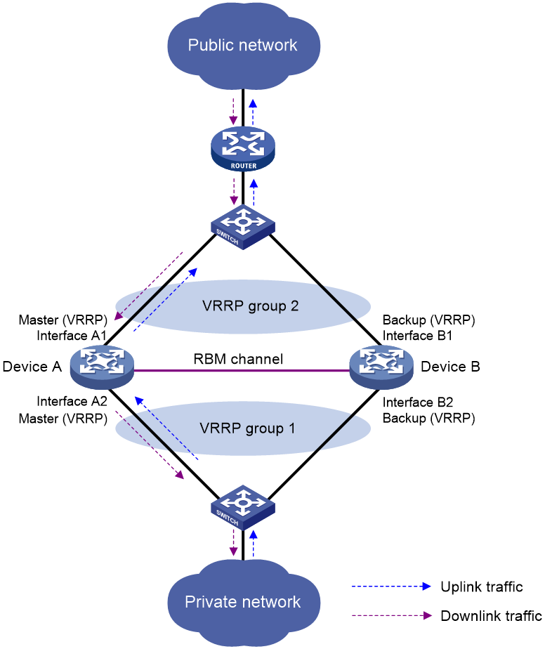
Typically, the master device in the VRRP group processes NAT services in the hot backup system. The following example illustrates how the hot backup system in active/standby mode ensures uninterrupted NAT services when the master device fails.
As shown in Figure 5, Device A acts as the primary device and Device B acts as the secondary device in a hot backup system. Device A synchronizes its session entries, session relation entries, and port block entries to Device B in real time through the hot backup channel. Downlinks of Device A and Device B are in VRRP group 1 and uplinks of Device A and Device B are in VRRP group 2. VRRP groups are associated with the hot backup system. RBM selects Device A as the master device for address translation based on the selection mechanism.
Figure 5 Hot backup in active/standby mode
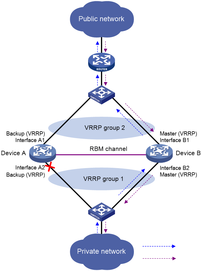
As shown in Figure 6, when Interface A2 of Device A fails, Device B becomes the master device in the VRRP group. Because Device B has NAT configuration information and service entries, NAT services are not interrupted after link switchover.
Figure 6 Traffic switchover in active/standby mode
Restrictions and guidelines for high availability configuration for NAT
The HA system supports NAT only in active/standby mode.
Configuring NAT on an HA system in active/standby mode
About this task
On an active/standby hot backup system, some translation rules for static translation, port block-based translation, or NAT server mappings issue the translated public IP addresses or the public IP addresses of internal servers to the address management module. Then, both the active and standby devices advertise the mappings between the public IP addresses and MAC addresses of their own physical interfaces to all nodes in the same LAN. As a result, the upstream Layer 3 device directly connected to the hot backup system might incorrectly send downlink packets to a VRRP backup device, causing service anomalies.
To avoid such an issue, bind address translation methods to the VRRP group in use. This ensures that only the VRRP master device responds to the ARP requests for the translated public IP addresses or the public IP addresses of internal servers. The MAC addresses in the responses are the virtual MAC address of the VRRP group.
Restrictions and guidelines
Bind address translation methods to the VRRP group in use on the primary device in the hot backup system.
Procedure
1. Enter system view.
system-view
2. Bind a translation method to a VRRP group. Choose the following steps to configure as needed.
3. Bind a VRRP group to the NAT address group.
a. Enter NAT address group view.
nat address-group group-id [ name group-name ]
b. Bind a VRRP group to the NAT address group.
vrrp vrid virtual-router-id
By default, a NAT address group is not bound to any VRRP group.
4. Bind a VRRP group to the NAT port block group.
a. Enter NAT port block group view.
nat port-block-group group-id
b. Bind a VRRP group to the NAT port block group.
vrrp vrid virtual-router-id
By default, a NAT port block group is not bound to any VRRP group.
5. Bind a VRRP group to the one-to-one mapping for outbound static NAT.
For more information, see "Configuring outbound one-to-one static NAT."
6. Bind a VRRP group to the net-to-net mapping for outbound static NAT.
For more information, see "Configuring outbound net-to-net static NAT."
7. Bind a VRRP group to the internal server.
a. Enter interface view.
interface interface-type interface-number
b. Bind a VRRP group to the internal server.
For more information, see "Configuring common NAT server mappings on an interface," "Configuring load sharing NAT server mappings on an interface," and "Configuring ACL-based NAT server mappings on an interface."
Configuring NAT logging
Configuring NAT session logging
About this task
NAT session logging records NAT session information, including translation information and access information.
A NAT device generates NAT session logs for the following events:
· NAT session establishment.
· NAT session removal. This event occurs when you add a configuration with a higher priority, remove a configuration, change ACLs, when a NAT session ages out, or when you manually delete a NAT session.
· Active NAT session logging.
Procedure
1. Enter system view.
system-view
2. Enable NAT logging.
nat log enable [ acl { ipv4-acl-number | name ipv4-acl-name } ]
By default, NAT logging is disabled.
3. Enable NAT session logging.
¡ For NAT session establishment events:
nat log flow-begin
¡ For NAT session removal events:
nat log flow-end
¡ For active NAT flows:
nat log flow-active time-value
By default, NAT session logging is disabled.
Configuring NAT user logging
About this task
The device enabled with NAT user logging generates a user log whenever it assigns or withdraws a port block. The log includes the private IP address, public IP address, and port block. You can use the public IP address and port numbers to locate the user's private IP address from the user logs.
The device generates NAT user logs when one of the following events occurs:
· A port block is assigned.
For the NAT static port block mapping, the device generates a user log when it translates the first connection from a private IP address.
For the NAT dynamic port block mapping, the device generates a user log when it assigns or extends a port block for a private IP address.
· A port block is withdrawn.
For the NAT static port block mapping, the device generates a user log when all connections from a private IP address are disconnected.
For the NAT dynamic port block mapping, the device generates a user log when all the following conditions are met:
¡ All connections from a private IP address are disconnected.
¡ The port blocks (including the extended ones) assigned to the private IP address are withdrawn.
¡ The corresponding mapping entry is deleted.
Prerequisites
Before configuring NAT user logging, you must configure the custom NAT log generation and outputting features. For more information, see fast log output in System Management Configuration Guide.
Procedure
1. Enter system view.
system-view
2. Enable NAT logging.
nat log enable [ acl { ipv4-acl-number | name ipv4-acl-name } ]
By default, NAT logging is disabled.
The acl keyword does not take effect on NAT user logging.
3. Enable NAT user logging. Choose the options to configure as needed:
¡ For port block assignment:
nat log port-block-assign
¡ For port block withdrawal:
nat log port-block-withdraw
By default, NAT user logging is disabled.
Configuring NAT port block assignment failure logging
About this task
The system generates logs when the system fails port block assignment.
Procedure
1. Enter system view.
system-view
2. Enable NAT logging.
nat log enable [ acl { ipv4-acl-number | name ipv4-acl-name } ]
By default, NAT logging is disabled.
3. Enable logging for port block assignment failures.
nat log port-block-alloc-fail
By default, logging is disabled for port block assignment failures.
Configuring NAT port allocation failure logging
About this task
The system generates logs when port allocation fails in dynamic NAT. Typically, the failure is caused by the fact that all ports are occupied in a port block.
Prerequisites
Before configuring this feature, you must configure the custom log outputting feature. For more information, see fast log output in System Management Configuration Guide.
Procedure
1. Enter system view.
system-view
2. Enable NAT logging.
nat log enable [ acl { ipv4-acl-number | name ipv4-acl-name } ]
By default, NAT logging is disabled.
3. Enable logging for NAT port allocation failures.
nat log port-alloc-fail
By default, logging is disabled for NAT port allocation failures.
Configuring threshold violation logging for port usage and port block usage
About this task
The system generates logs when port block usage or port usage in a port block exceeds the thresholds.
Procedure
1. Enter system view.
system-view
2. Enable NAT logging.
nat log enable [ acl { ipv4-acl-number | name ipv4-acl-name } ]
By default, NAT logging is disabled.
3. Enable threshold violation logging. Choose the options to configure as needed:
¡ Enable logging for port usage in port blocks and set the usage threshold.
nat log port-block port-usage threshold value
By default, logging for port usage in port blocks is disabled.
¡ Set the port block usage threshold.
nat log port-block usage threshold value
By default, the port block usage threshold is 90%.
Enabling the deletion of timestamps in TCP SYN and SYN ACK packets
About this task
With this feature configured, the system deletes the timestamps from the TCP SYN and SYN ACK packets after dynamic address translation.
If PAT mode is configured on an interface by using nat inbound or nat outbound, and the tcp_timestams and tcp_tw_recycle function is configured on the TCP server, TCP connections might not be established. To solve the problem, you can shut down the tcp_tw_recycle function or use the nat timestamp delete command.
Procedure
1. Enter system view.
system-view
2. Enable the deletion of timestamps in TCP SYN and SYN ACK packets
nat timestamp delete [ vpn-instance vpn-instance-name ]
By default, the deletion of timestamps in TCP SYN and SYN ACK packets is disabled.
You can enable this feature for multiple VPN instances by repeating the command with different VPN parameters.
Enabling the support for IP overlapping NAT address groups
About this task
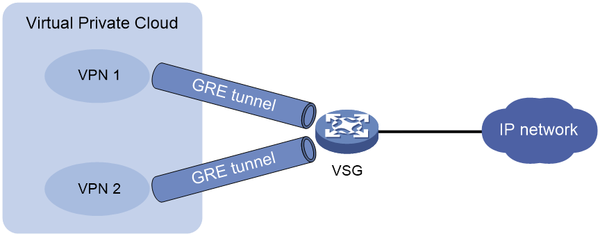
As shown in Figure 7, the VPN users in the VPC network access the VSG device through GRE tunnels. To allow VPC users in different VPN instances to access the public network, use different NAT address groups as a best practice. If the public address resources are not sufficient, enable this feature to allow overlapping addresses in NAT address groups. For more information about VPC, see MPLS L3VPN configuration in MPLS Configuration Guide.
Figure 7 VPC built on GRE tunnels
Restrictions and guidelines
With this feature enabled, NAT address groups cannot have overlapping IP addresses if multiple address translation rules are configured for users in the same VPN instance. Otherwise, the NAT service might not operate correctly.
Procedure
1. Enter system view.
system-view
2. Enable the support for IP overlapping NAT address groups
nat address-group ip-overlap enable
By default, overlapping addresses in different NAT address groups are not supported.
Verifying and maintaining NAT
Verifying NAT configuration
Perform all display tasks in in any view.
· Display all NAT configuration information.
display nat all
· Display static NAT mappings.
display nat static
· Display NAT address group information.
display nat address-group [ group-id ]
· Display inbound dynamic NAT configuration.
display nat inbound
· Display outbound dynamic NAT configuration.
display nat outbound
· Display NAT server mappings.
display nat server
· Display internal server group configuration.
display nat server-group [ group-id ]
· Display static outbound port block group mapping rules for NAT444.
display nat outbound port-block-group
· Display NAT port block group configuration.
display nat port-block-group [ group-id ]
· Display NAT DNS mappings.
display nat dns-map
· Display NAT logging configuration.
display nat log
Monitoring NAT running status
Perform display tasks in any view.
· Display information about NAT EIM entries.
display nat eim [ slot slot-number ] [ protocol { tcp | udp } ]
· Display information about NAT NO-PAT entries.
display nat no-pat [ slot slot-number ]
· Display NAT port block mappings.
display nat port-block { dynamic | static } [ slot slot-number ]
· Display NAT sessions.
display nat session [ { source-ip source-ip | destination-ip destination-ip } * [ vpn-instance vpn -instance-name ] ] [ slot slot-number ] [ verbose ]
Displaying NAT statistics
Perform all display tasks in in any view.
· Display NAT statistics.
display nat statistics [ summary ] [ slot slot-number ]
· Display NAT EIM entry statistics.
display nat eim statistics [ slot slot-number ]
Deleting NAT EIM entries
To delete NAT EIM entries, execute the following command in user view:
reset nat eim [ protocol { tcp | udp } ] [ slot slot-number ]
Clearing NAT sessions
To clear NAT sessions, execute the following command in user view:
reset nat session [ protocol { tcp | udp } ] [ slot slot-number ]
NAT configuration examples
Example: Configuring outbound one-to-one static NAT
Network configuration
Configure static NAT to allow the host at 10.110.10.8/24 to access the Internet.

Procedure
# Specify IP addresses for the interfaces on the router. (Details not shown.)
# Configure a one-to-one static NAT mapping between the private address 10.110.10.8 and the public address 202.38.1.100.
<Router> system-view
[Router] nat static outbound 10.110.10.8 202.38.1.100
# Enable static NAT on GigabitEthernet 0/0/2.
[Router] interface gigabitethernet 0/0/2
[Router-GigabitEthernet0/0/2] nat static enable
Verifying the configuration
# Verify that the host at 10.110.10.8/24 can access the server on the Internet. (Details not shown.)
# Display static NAT configuration.
[Router] display nat static
Static NAT mappings:
Totally 1 outbound static NAT mappings.
IP-to-IP:
Local IP : 10.110.10.8
Global IP : 202.38.1.100
Config status: Active
Interfaces enabled with static NAT:
Totally 1 interfaces enabled with static NAT.
Interface: GigabitEthernet0/0/2
Config status: Active
# Display NAT session information.
[Router] display nat session verbose
Initiator:
Source IP/port: 10.110.10.8/42496
Destination IP/port: 202.38.1.111/2048
DS-Lite tunnel peer: -
VPN instance/VLAN ID/VLL ID: -/-/-
Protocol: ICMP(1)
Inbound interface: GigabitEthernet0/0/1
Responder:
Source IP/port: 202.38.1.111/42496
Destination IP/port: 202.38.1.100/0
DS-Lite tunnel peer: -
VPN instance/VLAN ID/VLL ID: -/-/-
Protocol: ICMP(1)
Inbound interface: GigabitEthernet0/0/2
State: ICMP_REPLY
Application: INVALID
Start time: 2019-08-16 09:30:49 TTL: 27s
Initiator->Responder: 5 packets 420 bytes
Responder->Initiator: 5 packets 420 bytes
Total sessions found: 1
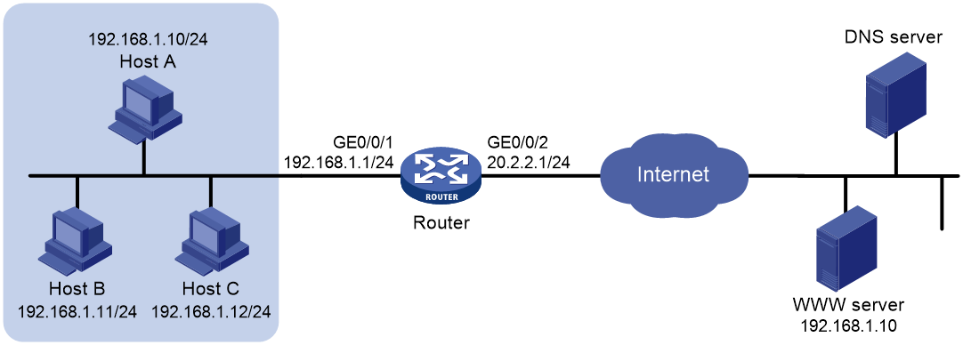
Example: Configuring outbound dynamic NAT (non-overlapping addresses)
Network configuration
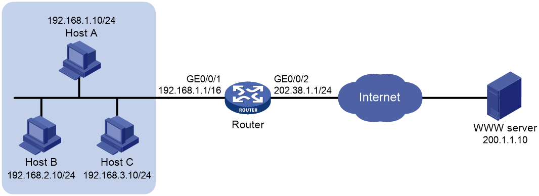
As shown in Figure 9, a company has a private address 192.168.0.0/16 and two public IP addresses 202.38.1.2 and 202.38.1.3. Configure outbound dynamic NAT to allow only internal users on subnet 192.168.1.0/24 to access the Internet.
Procedure
# Specify IP addresses for the interfaces on the router. (Details not shown.)
# Configure address group 0, and add an address range from 202.38.1.2 to 202.38.1.3 to the group.
<Router> system-view
[Router] nat address-group 0
[Router-address-group-0] address 202.38.1.2 202.38.1.3
[Router-address-group-0] quit
# Configure ACL 2000 to identify packets from subnet 192.168.1.0/24.
[Router] acl basic 2000
[Router-acl-ipv4-basic-2000] rule permit source 192.168.1.0 0.0.0.255
[Router-acl-ipv4-basic-2000] quit
# Enable outbound dynamic PAT on GigabitEthernet 0/0/2. The source IP addresses of the packets permitted by the ACL rule is translated into the addresses in address group 0.
[Router] interface gigabitethernet 0/0/2
[Router-GigabitEthernet0/0/2] nat outbound 2000 address-group 0
Verifying the configuration
# Verify that Host A can access the WWW server, while Host B cannot. (Details not shown.)
# Display all NAT configuration and statistics.
[Router] display nat all
NAT address group information:
Totally 1 NAT address groups.
Address group 0:
Port range: 1-65535
Address information:
Start address End address
202.38.1.2 202.38.1.3
NAT outbound information:
Totally 1 NAT outbound rules.
Interface: GigabitEthernet0/0/2
ACL: 2000 Address group: 0 Port-preserved: N
NO-PAT: N Reversible: N
Config status: Active
NAT logging:
Log enable : Disabled
Flow-begin : Disabled
Flow-end : Disabled
Flow-active : Disabled
Port-block-assign : Disabled
Port-block-withdraw : Disabled
Port-alloc-fail : Enabled
Port-block-alloc-fail : Disabled
Port-usage : Disabled
Port-block-usage : Enabled(40%)
NAT mapping behavior:
Mapping mode : Address and Port-Dependent
ACL : ---
Config status: Active
NAT ALG:
DNS : Enabled
FTP : Enabled
H323 : Disabled
ICMP-ERROR : Enabled
ILS : Disabled
MGCP : Disabled
NBT : Disabled
PPTP : Enabled
RTSP : Enabled
RSH : Disabled
SCCP : Disabled
SIP : Disabled
SQLNET : Disabled
TFTP : Disabled
XDMCP : Disabled
# Display NAT session information generated when Host A accesses the WWW server.
[Router] display nat session verbose
Initiator:
Source IP/port: 192.168.1.10/52992
Destination IP/port: 200.1.1.10/2048
DS-Lite tunnel peer: -
VPN instance/VLAN ID/VLL ID: -/-/-
Protocol: ICMP(1)
Inbound interface: GigabitEthernet0/0/1
Responder:
Source IP/port: 200.1.1.10/4
Destination IP/port: 202.38.1.3/0
DS-Lite tunnel peer: -
VPN instance/VLAN ID/VLL ID: -/-/-
Protocol: ICMP(1)
Inbound interface: GigabitEthernet0/0/2
State: ICMP_REPLY
Application: INVALID
Start time: 2019-08-15 14:53:29 TTL: 12s
Initiator->Responder: 1 packets 84 bytes
Responder->Initiator: 1 packets 84 bytes
Total sessions found: 1
Example: Configuring outbound bidirectional NAT
Network configuration
As shown in Figure 10, the private network where the Web server resides overlaps with the company private network 192.168.1.0/24. The company has two public IP addresses 202.38.1.2 and 202.38.1.3. Configure NAT to allow internal users to access the external Web server by using the server's domain name.
Analysis
To meet the network configuration, you must perform the following tasks:
· Configure inbound dynamic NAT ALG to make sure the internal host reaches the Web server instead of another internal host. NAT ALG can translate the Web server's IP address in the DNS reply payload to a dynamically assigned public address.
· Configure outbound dynamic NAT to translate the source IP address of packets from an internal host to a dynamically assigned public address.
· Add a static route to the public IP address of the external Web server.
Procedure
# Specify IP addresses for the interfaces on the router. (Details not shown.)
# Enable NAT ALG for DNS.
<Router> system-view
[Router] nat alg dns
# Configure ACL 2000 to identify packets from subnet 192.168.1.0/24.
[Router] acl basic 2000
[Router-acl-ipv4-basic-2000] rule permit source 192.168.1.0 0.0.0.255
[Router-acl-ipv4-basic-2000] quit
# Create address group 1.
[Router] nat address-group 1
# Add address 202.38.1.2 to address group 1..
[Router-address-group-1] address 202.38.1.2 202.38.1.2
[Router-address-group-1] quit
# Create address group 2.
[Router] nat address-group 2
# Add address 202.38.1.3 to address group 2.
[Router-address-group-2] address 202.38.1.3 202.38.1.3
[Router-address-group-2] quit
# Enable inbound NO-PAT on GigabitEthernet0/0/2 to translate the source IP address in the DNS reply payload into the address in address group 1, and allow reverse translation.
[Router] interface gigabitethernet 0/0/2
[Router-GigabitEthernet0/0/2] nat inbound 2000 address-group 1 no-pat reversible
# Enable outbound PAT on GigabitEthernet 0/0/2 to translate the source address of outgoing packets into the address in address group 2.
[Router-GigabitEthernet0/0/2] nat outbound 2000 address-group 2
# Configure a static route to 202.38.1.2 with GigabitEthernet 0/0/2 as the output interface and 20.2.2.2 as the next hop. (The next hop address varies by network.)
[Router] ip route-static 202.38.1.2 32 gigabitethernet 0/0/2 20.2.2.2
Verifying the configuration
# Verify that Host A can access the Web server by using its domain name. (Details not shown.)
# Display all NAT configuration and statistics.
[Router] display nat all
NAT address group information:
Totally 2 NAT address groups.
Address group 1:
Port range: 1-65535
Address information:
Start address End address
202.38.1.2 202.38.1.2
Address group 2:
Port range: 1-65535
Address information:
Start address End address
202.38.1.3 202.38.1.3
NAT inbound information:
Totally 1 NAT inbound rules.
Interface: GigabitEthernet0/0/2
ACL: 2000 Address group: 1 Add route: N
NO-PAT: Y Reversible: Y
Service card: Slot 2
Config status: Active
NAT outbound information:
Totally 1 NAT outbound rules.
Interface: GigabitEthernet0/0/2
ACL: 2000 Address group: 2 Port-preserved: N
NO-PAT: N Reversible: N
Service card: Slot 2
Config status: Active
NAT logging:
Log enable : Disabled
Flow-begin : Disabled
Flow-end : Disabled
Flow-active : Disabled
Port-block-assign : Disabled
Port-block-withdraw : Disabled
Port-alloc-fail : Enabled
Port-block-alloc-fail : Disabled
Port-usage : Disabled
Port-block-usage : Enabled(40%)
NAT mapping behavior:
Mapping mode : Address and Port-Dependent
ACL : ---
Config status: Active
NAT ALG:
DNS : Enabled
FTP : Enabled
H323 : Disabled
ICMP-ERROR : Enabled
ILS : Disabled
MGCP : Disabled
NBT : Disabled
PPTP : Enabled
RTSP : Enabled
RSH : Disabled
SCCP : Disabled
SIP : Disabled
SQLNET : Disabled
TFTP : Disabled
XDMCP : Disabled
# Display NAT sessions that are generated when Host A accesses the Web server.
[Router] display nat session verbose
Initiator:
Source IP/port: 192.168.1.10/1694
Destination IP/port: 202.38.1.2/8080
DS-Lite tunnel peer: -
VPN instance/VLAN ID/VLL ID: -/-/-
Protocol: TCP(6)
Inbound interface: GigabitEthernet0/0/1
Responder:
Source IP/port: 192.168.1.10/8080
Destination IP/port: 202.38.1.3/1025
DS-Lite tunnel peer: -
VPN instance/VLAN ID/VLL ID: -/-/-
Protocol: TCP(6)
Inbound interface: GigabitEthernet0/0/2
State: TCP_ESTABLISHED
Application: HTTP
Role: -
Failover group ID: -
Start time: 2019-12-15 14:53:29 TTL: 3597s
Initiator->Responder: 7 packets 308 bytes
Responder->Initiator: 5 packets 312 bytes
Total sessions found: 1
Example: Configuring NAT Server for external-to-internal access
Network configuration
As shown in Figure 11, two Web servers, one FTP server and one SMTP server are in the internal network to provide services for external users. The internal network address is 10.110.0.0/16. The company has three public IP addresses from 202.38.1.1/24 to 202.38.1.3/24.
Configure the NAT Server feature to allow the external user to use public address 202.38.1.1/24 to access the internal servers.

Procedure
# Specify IP addresses for the interfaces on the router. (Details not shown.)
# Enter interface view of GigabitEthernet 0/0/2.
<Router> system-view
[Router] interface gigabitethernet 0/0/2
# Configure a NAT server mapping to allow external users to access the FTP server by using address 202.38.1.1 and port 21.
[Router-GigabitEthernet0/0/2] nat server protocol tcp global 202.38.1.1 21 inside 10.110.10.3 ftp
# Configure a NAT server mapping to allow external users to access the Web server 1 by using address 202.38.1.1 and port 80.
[Router-GigabitEthernet0/0/2] nat server protocol tcp global 202.38.1.1 80 inside 10.110.10.1 http
# Configure a NAT server mapping to allow external users to access the Web server 2 by using address 202.38.1.1 and port 8080.
[Router-GigabitEthernet0/0/2] nat server protocol tcp global 202.38.1.1 8080 inside 10.110.10.2 http
# Configure a NAT server mapping to allow external users to access the SMTP server by using address 202.38.1.1 and port number defined by SMTP.
[Router-GigabitEthernet0/0/2] nat server protocol tcp global 202.38.1.1 smtp inside 10.110.10.4 smtp
Verifying the configuration
# Verify that the host on the external network can access the internal servers by using the public addresses. (Details not shown.)
# Display all NAT configuration and statistics.
[Router] display nat all
NAT internal server information:
Totally 4 internal servers.
Interface: GigabitEthernet0/0/2
Protocol: 6(TCP)
Global IP/port: 202.38.1.1/21
Local IP/port : 10.110.10.3/21
Config status : Active
Interface: GigabitEthernet0/0/2
Protocol: 6(TCP)
Global IP/port: 202.38.1.1/25
Local IP/port : 10.110.10.4/25
Config status : Active
Interface: GigabitEthernet0/0/2
Protocol: 6(TCP)
Global IP/port: 202.38.1.1/80
Local IP/port : 10.110.10.1/80
Config status : Active
Interface: GigabitEthernet0/0/2
Protocol: 6(TCP)
Global IP/port: 202.38.1.1/8080
Local IP/port : 10.110.10.2/80
Config status : Active
NAT logging:
Log enable : Disabled
Flow-begin : Disabled
Flow-end : Disabled
Flow-active : Disabled
Port-block-assign : Disabled
Port-block-withdraw : Disabled
Port-alloc-fail : Enabled
Port-block-alloc-fail : Disabled
Port-usage : Disabled
Port-block-usage : Enabled(40%)
NAT mapping behavior:
Mapping mode : Address and Port-Dependent
ACL : ---
Config status: Active
NAT ALG:
DNS : Enabled
FTP : Enabled
H323 : Disabled
ICMP-ERROR : Enabled
ILS : Disabled
MGCP : Disabled
NBT : Disabled
PPTP : Enabled
RTSP : Enabled
RSH : Disabled
SCCP : Disabled
SIP : Disabled
SQLNET : Disabled
TFTP : Disabled
XDMCP : Disabled
# Display NAT session information generated when the host accesses the FTP server.
[Router] display nat session verbose
Initiator:
Source IP/port: 202.38.1.10/1694
Destination IP/port: 202.38.1.1/21
DS-Lite tunnel peer: -
VPN instance/VLAN ID/VLL ID: -/-/-
Protocol: TCP(6)
Inbound interface: GigabitEthernet0/0/2
Responder:
Source IP/port: 10.110.10.3/21
Destination IP/port: 202.38.1.10/1694
DS-Lite tunnel peer: -
VPN instance/VLAN ID/VLL ID: -/-/-
Protocol: TCP(6)
Inbound interface: GigabitEthernet0/0/1
State: TCP_ESTABLISHED
Application: FTP
Start time: 2019-08-15 14:53:29 TTL: 3597s
Initiator->Responder: 7 packets 308 bytes
Responder->Initiator: 5 packets 312 bytes
Total sessions found: 1
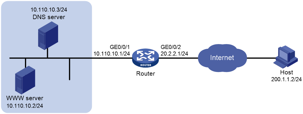
Example: Configuring NAT Server for external-to-internal access through domain name
Network configuration
As shown in Figure 12, Web server at 10.110.10.2/24 in the internal network provides services for external users. A DNS server at 10.110.10.3/24 is used to resolve the domain name of the Web server. The company has two public IP addresses: 202.38.1.2 and 202.38.1.3.
Configure NAT Server to allow external users to access the internal Web server by using the domain name.
Analysis
To meet the network requirements, you must perform the following tasks:
· Configure a NAT server mapping to map the private IP address and port of the DNS server to a public address and port. The mapping allows the external host to access the internal DNS server for domain name resolution.
· Enable ALG for DNS and configure outbound dynamic NAT to translate the private IP address of the Web server in the payload of the DNS response packet into a public IP address.
Procedure
# Specify IP addresses for the interfaces on the router. (Details not shown.)
# Enable NAT ALG for DNS.
<Router> system-view
[Router] nat alg dns
# Configure ACL 2000 to identify packets from 10.110.10.2.
[Router] acl basic 2000
[Router-acl-ipv4-basic-2000] rule permit source 10.110.10.2 0
[Router-acl-ipv4-basic-2000] quit
# Create address group 1.
[Router] nat address-group 1
# Add address 202.38.1.3 to the group.
[Router-address-group-1] address 202.38.1.3 202.38.1.3
[Router-address-group-1] quit
# Configure a NAT server mapping on GigabitEthernet 0/0/2 to map the address 202.38.1.1 to 10.110.10.3. External users can access the internal DNS server.
[Router] interface gigabitethernet 0/0/2
[Router-GigabitEthernet0/0/2] nat server protocol udp global 202.38.1.2 inside 10.110.10.3 dns
# Enable outbound NO-PAT on GigabitEthernet 0/0/2. Use the address in address group 1 to translate the private address in DNS response payload, and allow reversible NAT.
[Router-GigabitEthernet0/0/2] nat outbound 2000 address-group 1 no-pat reversible
Verifying the configuration
# Verify that the host on the external network can access the internal Web server by using the server's domain name. (Details not shown.)
# Display all NAT configuration and statistics.
[Router] display nat all
NAT address group information:
Totally 1 NAT address groups.
Address group 1:
Port range: 1-65535
Address information:
Start address End address
202.38.1.3 202.38.1.3
NAT outbound information:
Totally 1 NAT outbound rules.
Interface: GigabitEthernet0/0/2
ACL: 2000 Address group: 1 Port-preserved: N
NO-PAT: Y Reversible: Y
Service card: Slot 2
Config status: Active
NAT internal server information:
Totally 1 internal servers.
Interface: GigabitEthernet0/0/2
Protocol: 17(UDP)
Global IP/port: 202.38.1.2/53
Local IP/port : 10.110.10.3/53
Service card : Slot 2
Config status : Active
NAT logging:
Log enable : Disabled
Flow-begin : Disabled
Flow-end : Disabled
Flow-active : Disabled
Port-block-assign : Disabled
Port-block-withdraw : Disabled
Port-alloc-fail : Enabled
Port-block-alloc-fail : Disabled
Port-usage : Disabled
Port-block-usage : Enabled(40%)
NAT mapping behavior:
Mapping mode : Address and Port-Dependent
ACL : ---
Config status: Active
NAT ALG:
DNS : Enabled
FTP : Enabled
H323 : Disabled
ICMP-ERROR : Enabled
ILS : Disabled
MGCP : Disabled
NBT : Disabled
PPTP : Enabled
RTSP : Enabled
RSH : Disabled
SCCP : Disabled
SIP : Disabled
SQLNET : Disabled
TFTP : Disabled
XDMCP : Disabled
# Display NAT sessions that are generated when the host accesses the Web server.
[Router] display nat session verbose
Initiator:
Source IP/port: 200.1.1.2/1694
Destination IP/port: 202.38.1.3/8080
DS-Lite tunnel peer: -
VPN instance/VLAN ID/VLL ID: -/-/-
Protocol: TCP(6)
Inbound interface: GigabitEthernet0/0/2
Responder:
Source IP/port: 10.110.10.2/8080
Destination IP/port: 202.1.1.2/1694
DS-Lite tunnel peer: -
VPN instance/VLAN ID/VLL ID: -/-/-
Protocol: TCP(6)
Inbound interface: GigabitEthernet0/0/1
State: TCP_ESTABLISHED
Application: HTTP
Role: -
Failover group ID: -
Start time: 2019-12-15 14:53:29 TTL: 3597s
Initiator->Responder: 7 packets 308 bytes
Responder->Initiator: 5 packets 312 bytes
Total sessions found: 1
Example: Configuring NAT Server for external-to-internal access through domain name
Network configuration
As shown in Figure 13, an intranet uses the subnet 192.168.1.0/24. The Web server at 192.168.1.2/24 provides Web services for external users and the DNS server at 192.168.1.3/24 resolves the domain name of the Web server. The company has three public addresses 202.38.1.2 through 202.38.1.4.
Configure NAT to allow external host at 192.168.1.2 in the external network to use the domain name to access the internal Web server.
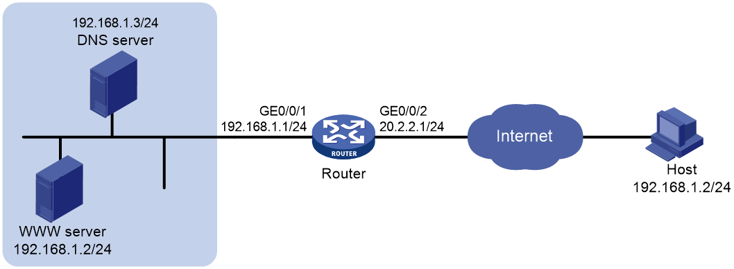
Analysis
To meet the network requirements, you must perform the following tasks:
· Configure NAT Server to map the private IP address and port of the DNS server to a public IP address and port. NAT Server allows the external host to access the internal DNS server for domain name resolution.
· Configure outbound dynamic NAT and enable ALG for DNS. The Web server's IP address is the same as the external host's IP address. NAT ALG can translate the Web server's private address in the payload of the DNS response packet to a dynamically assigned public address.
· Configure inbound dynamic NAT. The external host's IP address is the same as the Web server's IP address. Inbound dynamic NAT can translate the external host's IP address into a dynamically assigned public address.
· Add a static route to the public IP address of the external host with GigabitEthernet 0/0/2 as the output interface.
Procedure
# Specify IP addresses for the interfaces on the router. (Details not shown.)
# Enable NAT ALG for DNS.
<Router> system-view
[Router] nat alg dns
# Configure ACL 2000 to identify packets from subnet 192.168.1.0/24.
[Router] acl basic 2000
[Router-acl-ipv4-basic-2000] rule permit source 192.168.1.0 0.0.0.255
[Router-acl-ipv4-basic-2000] quit
# Create address group 1.
[Router] nat address-group 1
# Add address 202.38.1.2 to address group 1.
[Router-address-group-1] address 202.38.1.2 202.38.1.2
[Router-address-group-1] quit
# Create address group 2.
[Router] nat address-group 2
# Add address 202.38.1.3 to address group 2.
[Router-address-group-2] address 202.38.1.3 202.38.1.3
[Router-address-group-2] quit
# Configure NAT Server on GigabitEthernet 0/0/2 to allow external hosts to access the internal DNS server by using address 202.38.1.4.
[Router] interface gigabitethernet 0/0/2
[Router-GigabitEthernet0/0/2] nat server protocol udp global 202.38.1.4 inside 192.168.1.3 dns
# Enable outbound NO-PAT on GigabitEthernet 0/0/2 to translate IP address of the Web server in the DNS response payload into the address in address group 1, and allow reversible NAT.
[Router-GigabitEthernet0/0/2] nat outbound 2000 address-group 1 no-pat reversible
# Enable inbound PAT on GigabitEthernet 0/0/2 to translate the source address of packets going to the internal network to the address in address group 2.
[Router-GigabitEthernet0/0/2] nat inbound 2000 address-group 2
# Configure a static route to 202.38.1.3 with GigabitEthernet 0/0/2 as the output interface and 20.2.2.2 as the next hop. (The next hop address varies by network.)
[Router] ip route-static 202.38.1.3 32 gigabitethernet 0/0/2 20.2.2.2
Verifying the configuration
# Verify that the host on the external network can use the domain name to access the internal Web server whose address is the same as the host. (Details not shown.)
# Display all NAT configuration and statistics.
[Router] display nat all
NAT address group information:
Totally 2 NAT address groups.
Address group 1:
Port range: 1-65535
Address information:
Start address End address
202.38.1.2 202.38.1.2
Address group 2:
Port range: 1-65535
Address information:
Start address End address
202.38.1.3 202.38.1.3
NAT inbound information:
Totally 1 NAT inbound rules.
Interface: GigabitEthernet0/0/2
ACL: 2000 Address group: 2 Add route: N
NO-PAT: N Reversible: N
Service card: Slot 2
Config status: Active
NAT outbound information:
Totally 1 NAT outbound rules.
Interface: GigabitEthernet0/0/2
ACL: 2000 Address group: 1 Port-preserved: N
NO-PAT: Y Reversible: Y
Service card: Slot 2
Config status: Active
NAT internal server information:
Totally 1 internal servers.
Interface: GigabitEthernet0/0/2
Protocol: 17(UDP)
Global IP/port: 202.38.1.4/53
Local IP/port : 200.1.1.3/53
Service card : Slot 2
Config status : Active
NAT logging:
Log enable : Disabled
Flow-begin : Disabled
Flow-end : Disabled
Flow-active : Disabled
Port-block-assign : Disabled
Port-block-withdraw : Disabled
Port-alloc-fail : Enabled
Port-block-alloc-fail : Disabled
Port-usage : Disabled
Port-block-usage : Enabled(40%)
NAT mapping behavior:
Mapping mode : Address and Port-Dependent
ACL : ---
Config status: Active
NAT ALG:
DNS : Enabled
FTP : Enabled
H323 : Disabled
ICMP-ERROR : Enabled
ILS : Disabled
MGCP : Disabled
NBT : Disabled
PPTP : Enabled
RTSP : Enabled
RSH : Disabled
SCCP : Disabled
SIP : Disabled
SQLNET : Disabled
TFTP : Disabled
XDMCP : Disabled
# Display NAT sessions that are generated when the host accesses the Web server.
[Router] display nat session verbose
Initiator:
Source IP/port: 192.168.1.2/1694
Destination IP/port: 202.38.1.2/8080
DS-Lite tunnel peer: -
VPN instance/VLAN ID/VLL ID: -/-/-
Protocol: TCP(6)
Inbound interface: GigabitEthernet0/0/2
Responder:
Source IP/port: 192.168.1.2/8080
Destination IP/port: 202.38.1.3/1025
DS-Lite tunnel peer: -
VPN instance/VLAN ID/VLL ID: -/-/-
Protocol: TCP(6)
Inbound interface: GigabitEthernet0/0/1
State: TCP_ESTABLISHED
Application: HTTP
Role: -
Failover group ID: -
Start time: 2019-12-15 14:53:29 TTL: 3597s
Initiator->Responder: 7 packets 308 bytes
Responder->Initiator: 5 packets 312 bytes
Total sessions found: 1
Example: Configuring NAT hairpin in C/S mode
Network configuration
As shown in Figure 14, the internal FTP server at 192.168.1.4/24 provides services for internal and external users. The private network uses two public IP addresses 202.38.1.1 and 202.38.1.2.
Configure NAT hairpin in C/S mode to allow external and internal users to access the internal FTP server by using public IP address 202.38.1.2.

Analysis
To allow external hosts to access the internal FTP server by using a public IP address, configure NAT Server on the interface connected to the external network.
To allow internal hosts to access the internal FTP server by using a public IP address, perform the following tasks:
· Enable NAT hairpin on the interface connected to the internal network.
· Configure outbound NAT on the interface where the NAT server mapping is configured. The destination address is translated by matching the NAT server mapping. The source address is translated by matching the outbound NAT.
Procedure
# Specify IP addresses for the interfaces on the router. (Details not shown.)
# Configure ACL 2000 to identify packets from subnet 192.168.1.0/24.
<Router> system-view
[Router] acl basic 2000
[Router-acl-ipv4-basic-2000] rule permit source 192.168.1.0 0.0.0.255
[Router-acl-ipv4-basic-2000] quit
# Configure a NAT server mapping on GigabitEthernet 0/0/2 to map the IP address of the FTP server to a public address, allowing external users to access the internal FTP server.
[Router] interface gigabitethernet 0/0/2
[Router-GigabitEthernet0/0/2] nat server protocol tcp global 202.38.1.2 inside 192.168.1.4 ftp
# Enable outbound NAT with Easy IP on GigabitEthernet 0/0/2 so that NAT translates the source addresses of the packets from internal hosts into the IP address of GigabitEthernet 0/0/2.
[Router-GigabitEthernet0/0/2] nat outbound 2000
# Enable NAT hairpin on GigabitEthernet 0/0/1.
[Router] interface gigabitethernet 0/0/1
[Router-GigabitEthernet0/0/1] nat hairpin enable
Verifying the configuration
# Verify that both internal and external hosts can access the internal FTP server through the public address. (Details not shown.)
# Display all NAT configuration and statistics.
[Router]display nat all
NAT outbound information:
Totally 1 NAT outbound rules.
Interface: GigabitEthernet0/0/2
ACL: 2000 Address group: --- Port-preserved: N
NO-PAT: N Reversible: N
Config status: Active
NAT internal server information:
Totally 1 internal servers.
Interface: GigabitEthernet0/0/2
Protocol: 6(TCP)
Global IP/port: 202.38.1.2/21
Local IP/port : 192.168.1.4/21
Config status : Active
NAT logging:
Log enable : Disabled
Flow-begin : Disabled
Flow-end : Disabled
Flow-active : Disabled
Port-block-assign : Disabled
Port-block-withdraw : Disabled
Port-alloc-fail : Enabled
Port-block-alloc-fail : Disabled
Port-usage : Disabled
Port-block-usage : Enabled(40%)
NAT hairpinning:
Totally 1 interfaces enabled with NAT hairpinning.
Interface: GigabitEthernet0/0/1
Config status: Active
NAT mapping behavior:
Mapping mode : Address and Port-Dependent
ACL : ---
Config status: Active
NAT ALG:
DNS : Enabled
FTP : Enabled
H323 : Disabled
ICMP-ERROR : Enabled
ILS : Disabled
MGCP : Disabled
NBT : Disabled
PPTP : Enabled
RTSP : Enabled
RSH : Disabled
SCCP : Disabled
SIP : Disabled
SQLNET : Disabled
TFTP : Disabled
XDMCP : Disabled
# Display NAT session information generated when Host A accesses the FTP server.
[Router] display nat session verbose
Initiator:
Source IP/port: 192.168.1.2/1694
Destination IP/port: 202.38.1.2/21
DS-Lite tunnel peer: -
VPN instance/VLAN ID/VLL ID: -/-/-
Protocol: TCP(6)
Inbound interface: GigabitEthernet0/0/1
Responder:
Source IP/port: 192.168.1.4/21
Destination IP/port: 202.38.1.1/1025
DS-Lite tunnel peer: -
VPN instance/VLAN ID/VLL ID: -/-/-
Protocol: TCP(6)
Inbound interface: GigabitEthernet0/0/1
State: TCP_ESTABLISHED
Application: FTP
Start time: 2019-08-15 14:53:29 TTL: 3597s
Initiator->Responder: 7 packets 308 bytes
Responder->Initiator: 5 packets 312 bytes
Example: Configuring NAT hairpin in P2P mode
Network configuration
In the P2P application, internal clients must register their IP address to the external server and the server records the registered IP addresses and port numbers of the internal clients. An internal client must request the IP address and port number of another client from the external server before accessing the client.
Configure NAT hairpin so that:
· The internal clients can register the same public address to the external server.
· The internal clients can access each other through the IP address and port number obtained from the server.
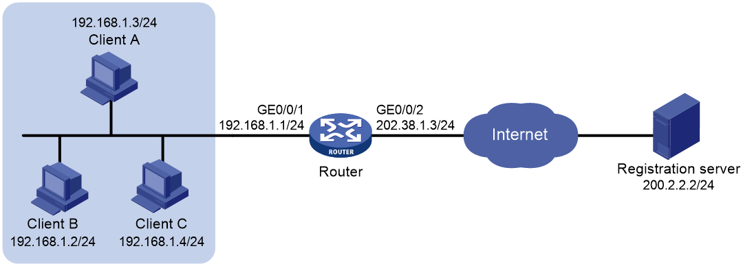
Analysis
To meet the network requirements, you must perform the following tasks:
· Configure outbound dynamic PAT on the interface connected to the external network, so the internal clients can access the external server for registration.
· Configure the mapping behavior for PAT as Endpoint-Independent Mapping because the registered IP address and port number should be accessible for any source address.
· Enable NAT hairpin on the interface connected to the internal network so that internal clients can access each other through the public address.
Procedure
# Specify IP addresses for the interfaces on the router. (Details not shown.)
# Configure ACL 2000 to identify packets from subnet 192.168.1.0/24.
<Router> system-view
[Router] acl basic 2000
[Router-acl-ipv4-basic-2000] rule permit source 192.168.1.0 0.0.0.255
[Router-acl-ipv4-basic-2000] quit
# Configure outbound dynamic PAT with Easy IP on GigabitEthernet 0/0/2. The IP address of GigabitEthernet 0/0/2 is used as the public address for the source address translation of the packets from internal to external.
[Router] interface gigabitethernet 0/0/2
[Router-GigabitEthernet0/0/2] nat outbound 2000
# Configure the Endpoint-Independent Mapping mode for PAT. For packets with the same source address and port number and permitted by ACL 2000, the source address and port number are translated to the same public address and port number.
[Router] nat mapping-behavior endpoint-independent acl 2000
# Enable NAT hairpin on GigabitEthernet 0/0/1.
[Router] interface gigabitethernet 0/0/1
[Router-GigabitEthernet0/0/1] nat hairpin enable
Verifying the configuration
# Verify that Host A, Host B, and Host C can access each other after they register their IP addresses and port numbers to the external server. (Details not shown.)
# Display all NAT configuration and statistics.
[Router] display nat all
NAT outbound information:
Totally 1 NAT outbound rules.
Interface: GigabitEthernet0/0/2
ACL: 2000 Address group: --- Port-preserved: N
NO-PAT: N Reversible: N
Config status: Active
NAT logging:
Log enable : Disabled
Flow-begin : Disabled
Flow-end : Disabled
Flow-active : Disabled
Port-block-assign : Disabled
Port-block-withdraw : Disabled
Port-alloc-fail : Enabled
Port-block-alloc-fail : Disabled
Port-usage : Disabled
Port-block-usage : Enabled(40%)
NAT hairpinning:
Totally 1 interfaces enabled with NAT hairpinning.
Interface: GigabitEthernet0/0/1
Config status: Active
NAT mapping behavior:
Mapping mode : Endpoint-Independent
ACL : 2000
Config status: Active
NAT ALG:
DNS : Enabled
FTP : Enabled
H323 : Disabled
ICMP-ERROR : Enabled
ILS : Disabled
MGCP : Disabled
NBT : Disabled
PPTP : Enabled
RTSP : Enabled
RSH : Disabled
SCCP : Disabled
SIP : Disabled
SQLNET : Disabled
TFTP : Disabled
XDMCP : Disabled
# Display NAT session information generated when Client A accesses Client B.
[Router] display nat session verbose
Initiator:
Source IP/port: 192.168.1.3/44929
Destination IP/port: 202.38.1.3/1
DS-Lite tunnel peer: -
VPN instance/VLAN ID/VLL ID: -/-/-
Protocol: UDP(17)
Inbound interface: GigabitEthernet0/0/1
Responder:
Source IP/port: 192.168.1.2/69
Destination IP/port: 202.38.1.3/1024
DS-Lite tunnel peer: -
VPN instance/VLAN ID/VLL ID: -/-/-
Protocol: UDP(17)
Inbound interface: GigabitEthernet0/0/1
State: UDP_READY
Application: TFTP
Start time: 2019-08-15 15:53:36 TTL: 46s
Initiator->Responder: 1 packets 56 bytes
Responder->Initiator: 1 packets 72 bytes
Total sessions found: 1
Example: Configuring twice NAT
Network configuration
As shown in Figure 16, two departments are in different VPN instances with overlapping addresses. Configure twice NAT so that Host A and Host B in different departments can access each other.
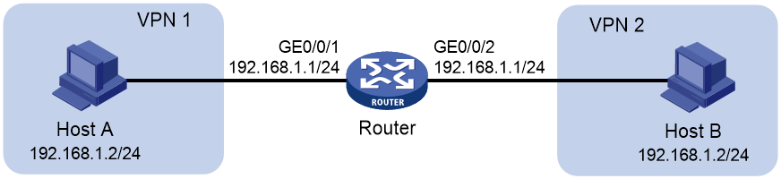
Analysis
This is a typical application of twice NAT. Both the source and destination addresses of packets between the two VPNs need to be translated. Configure static NAT on both interfaces connected to the VPNs on the NAT device.
Procedure
# Specify VPN instances and IP addresses for the interfaces on the router. (Details not shown.)
# Configure a static outbound NAT mapping between 192.168.1.2 in vpn 1 and 172.16.1.2 in vpn 2.
<Router> system-view
[Router] nat static outbound 192.168.1.2 vpn-instance vpn1 172.16.1.2 vpn-instance vpn2
# Configure a static outbound NAT mapping between 192.168.1.2 in vpn 2 and 172.16.2.2 in vpn 1.
[Router] nat static outbound 192.168.1.2 vpn-instance vpn2 172.16.2.2 vpn-instance vpn1
# Enable static NAT on GigabitEthernet 0/0/2.
[Router] interface gigabitethernet 0/0/2
[Router-GigabitEthernet0/0/2] nat static enable
# Enable static NAT on GigabitEthernet 0/0/1.
[Router] interface gigabitethernet 0/0/1
[Router-GigabitEthernet0/0/1] nat static enable
Verifying the configuration
# Verify that Host A and Host B can access each other. The public address for Host A is 172.16.1.2 and that for Host B is 172.16.2.2. (Details not shown.)
# Display all NAT configuration and statistics.
[Router] display nat all
Static NAT mappings:
Totally 2 outbound static NAT mappings.
IP-to-IP:
Local IP : 192.168.1.2
Global IP : 172.16.1.2
Local VPN : vpn1
Global VPN : vpn2
Config status: Active
IP-to-IP:
Local IP : 192.168.1.2
Global IP : 172.16.2.2
Local VPN : vpn2
Global VPN : vpn1
Config status: Active
Interfaces enabled with static NAT:
Totally 2 interfaces enabled with static NAT.
Interface: GigabitEthernet0/0/1
Config status: Active
Interface: GigabitEthernet0/0/2
Config status: Active
NAT logging:
Log enable : Disabled
Flow-begin : Disabled
Flow-end : Disabled
Flow-active : Disabled
Port-block-assign : Disabled
Port-block-withdraw : Disabled
Port-alloc-fail : Enabled
Port-block-alloc-fail : Disabled
Port-usage : Disabled
Port-block-usage : Enabled(40%)
NAT mapping behavior:
Mapping mode : Address and Port-Dependent
ACL : ---
Config status: Active
NAT ALG:
DNS : Enabled
FTP : Enabled
H323 : Disabled
ICMP-ERROR : Enabled
ILS : Disabled
MGCP : Disabled
NBT : Disabled
PPTP : Enabled
RTSP : Enabled
RSH : Disabled
SCCP : Disabled
SIP : Disabled
SQLNET : Disabled
TFTP : Disabled
XDMCP : Disabled
# Display NAT sessions that are generated when Host A accesses Host B.
[Router] display nat session verbose
Initiator:
Source IP/port: 192.168.1.2/42496
Destination IP/port: 172.16.2.2/2048
DS-Lite tunnel peer: -
VPN instance/VLAN ID/VLL ID: vpn1/-/-
Protocol: ICMP(1)
Inbound interface: GigabitEthernet0/0/1
Responder:
Source IP/port: 192.168.1.2/42496
Destination IP/port: 172.16.1.2/0
DS-Lite tunnel peer: -
VPN instance/VLAN ID/VLL ID: vpn2/-/-
Protocol: ICMP(1)
Inbound interface: GigabitEthernet0/0/2
State: ICMP_REPLY
Application: INVALID
Start time: 2019-08-16 09:30:49 TTL: 27s
Initiator->Responder: 5 packets 420 bytes
Responder->Initiator: 5 packets 420 bytes
Total sessions found: 1
Example: Configuring load sharing NAT Server
Network configuration
As shown in Figure 17, three FTP servers are in the intranet to provide FTP services for external users. Configure NAT so that these external users use the address 202.38.1.1/16 to access the servers and the three FTP servers implement load sharing.

Procedure
# Specify IP addresses for the interfaces on the router. (Details not shown.)
# Create NAT server group 0, and add members to the group.
<Router> system-view
[Router] nat server-group 0
[Router-nat-server-group-0] inside ip 10.110.10.1 port 21
[Router-nat-server-group-0] inside ip 10.110.10.2 port 21
[Router-nat-server-group-0] inside ip 10.110.10.3 port 21
[Router-nat-server-group-0] quit
# Associate NAT server group 0 with GigabitEthernet 0/0/2 so that servers in the server group can provide FTP services.
[Router] interface gigabitethernet 0/0/2
[Router-GigabitEthernet0/0/2] nat server protocol tcp global 202.38.1.1 ftp inside server-group 0
Verifying the configuration
# Verify that external hosts can access the internal FTP server group. (Details not shown.)
# Display all NAT configuration and statistics.
[Router] display nat all
NAT server group information:
Totally 1 NAT server groups.
Group Number Inside IP Port Weight
0 10.110.10.1 21 100
10.110.10.2 21 100
10.110.10.3 21 100
NAT internal server information:
Totally 1 internal servers.
Interface: GigabitEthernet0/0/2
Protocol: 6(TCP)
Global IP/port: 202.38.1.1/21
Local IP/port : server group 0
10.110.10.1/21 (Connections: 1)
10.110.10.2/21 (Connections: 2)
10.110.10.3/21 (Connections: 2)
Config status : Active
NAT logging:
Log enable : Disabled
Flow-begin : Disabled
Flow-end : Disabled
Flow-active : Disabled
Port-block-assign : Disabled
Port-block-withdraw : Disabled
Port-alloc-fail : Enabled
Port-block-alloc-fail : Disabled
Port-usage : Disabled
Port-block-usage : Enabled(40%)
NAT mapping behavior:
Mapping mode : Address and Port-Dependent
ACL : ---
Config status: Active
NAT ALG:
DNS : Enabled
FTP : Enabled
H323 : Disabled
ICMP-ERROR : Enabled
ILS : Disabled
MGCP : Disabled
NBT : Disabled
PPTP : Enabled
RTSP : Enabled
RSH : Disabled
SCCP : Disabled
SIP : Disabled
SQLNET : Disabled
TFTP : Disabled
XDMCP : Disabled
# Display NAT session information generated when external hosts access an internal FTP server.
[Router] display nat session verbose
Initiator:
Source IP/port: 202.38.1.25/53957
Destination IP/port: 202.38.1.1/21
DS-Lite tunnel peer: -
VPN instance/VLAN ID/VLL ID: -/-/-
Protocol: TCP(6)
Inbound interface: GigabitEthernet0/0/2
Responder:
Source IP/port: 10.110.10.3/21
Destination IP/port: 202.38.1.25/53957
DS-Lite tunnel peer: -
VPN instance/VLAN ID/VLL ID: -/-/-
Protocol: TCP(6)
Inbound interface: GigabitEthernet0/0/1
State: TCP_ESTABLISHED
Application: FTP
Start time: 2019-08-16 11:06:07 TTL: 26s
Initiator->Responder: 1 packets 60 bytes
Responder->Initiator: 2 packets 120 bytes
Total sessions found: 1
Example: Configuring NAT DNS mapping
Network configuration
As shown in Figure 18, the internal Web server at 10.110.10.1/16 and FTP server at 10.110.10.2/16 provide services for external users. The company has three public addresses 202.38.1.1 through 202.38.1.3. The DNS server at 202.38.1.4 is on the external network.
Configure NAT so that:
· The public IP address 202.38.1.2 is used by external users to access the Web and FTP servers.
· External users can use the public address or domain name of internal servers to access them.
· Internal users can access the internal servers by using their domain names.

Analysis
To meet the network requirements, perform the following tasks:
· Configure a NAT server mapping to map the public IP addresses and port numbers of the internal servers to a public address and port numbers so that external users can access the internal servers.
· Configure NAT DNS and NAT ALG so that the public IP address of the internal server in the payload of the DNS response packet can be translated to the private IP address.
Procedure
# Specify IP addresses for the interfaces on the router. (Details not shown.)
# Enable NAT ALG for DNS.
<Router> system-view
[Router] nat alg dns
# Enter interface view of GigabitEthernet 0/0/2.
[Router] interface gigabitethernet 0/0/2
# Configure a NAT server mapping to allow external hosts to access the internal Web server by using address 202.38.1.2.
[Router-GigabitEthernet0/0/2] nat server protocol tcp global 202.38.1.2 inside 10.110.10.1 http
# Configure a NAT server mapping to allow external hosts to access the internal FTP server by using address 202.38.1.2.
[Router-GigabitEthernet0/0/2] nat server protocol tcp global 202.38.1.2 inside 10.110.10.2 ftp
# Enable outbound NAT with Easy IP on GigabitEthernet 0/0/2.
[Router-GigabitEthernet0/0/2] nat outbound
# Configure two DNS mappings by mapping domain name www.example.com of the Web server to 202.38.1.2, and ftp.example.com of the FTP server to 202.38.1.2.
[Router] nat dns-map domain www.example.com protocol tcp ip 202.38.1.2 port http
[Router] nat dns-map domain ftp.example.com protocol tcp ip 202.38.1.2 port ftp
[Router] quit
Verifying the configuration
# Verify that both internal and external hosts can access the internal servers by using domain names. (Details not shown.)
# Display all NAT configuration and statistics.
[Router] display nat all
NAT outbound information:
Totally 1 NAT outbound rules.
Interface: GigabitEthernet0/0/2
ACL: --- Address group: --- Port-preserved: N
NO-PAT: N Reversible: N
Service card: Slot 2
Config status: Active
NAT internal server information:
Totally 2 internal servers.
Interface: GigabitEthernet0/0/2
Protocol: 6(TCP)
Global IP/port: 202.38.1.2/21
Local IP/port : 10.110.10.2/21
Service card : Slot 2
Config status : Active
Interface: GigabitEthernet0/0/2
Protocol: 6(TCP)
Global IP/port: 202.38.1.2/80
Local IP/port : 10.110.10.1/80
Service card : Slot 2
Config status : Active
NAT DNS mapping information:
Totally 2 NAT DNS mappings.
Domain name: ftp.example.com
Global IP : 202.38.1.2
Global port: 21
Protocol : TCP(6)
Config status: Active
Domain name: www.example.com
Global IP : 202.38.1.2
Global port: 80
Protocol : TCP(6)
Config status: Active
NAT logging:
Log enable : Disabled
Flow-begin : Disabled
Flow-end : Disabled
Flow-active : Disabled
Port-block-assign : Disabled
Port-block-withdraw : Disabled
Port-alloc-fail : Enabled
Port-block-alloc-fail : Disabled
Port-usage : Disabled
Port-block-usage : Enabled(40%)
NAT mapping behavior:
Mapping mode : Address and Port-Dependent
ACL : ---
Config status: Active
NAT ALG:
DNS : Enabled
FTP : Enabled
H323 : Disabled
ICMP-ERROR : Enabled
ILS : Disabled
MGCP : Disabled
NBT : Disabled
PPTP : Enabled
RTSP : Enabled
RSH : Disabled
SCCP : Disabled
SIP : Disabled
SQLNET : Disabled
TFTP : Disabled
XDMCP : Disabled
Example: Configuring NAT static port block mapping
Network configuration
As shown in Figure 19, configure NAT static port block mapping to allow users at private IP addresses 10.110.10.1 to 10.110.10.10 to use public IP address 202.38.1.100 for accessing the Internet. Configure the port range as 10001 to 15000, and set the port block size to 500.

Procedure
# Specify IP addresses for the interfaces on the router. (Details not shown.)
# Create NAT port block group 1.
<Router> system-view
[Router] nat port-block-group 1
# Add the private IP addresses from 10.110.10.1 to 10.110.10.10 to the port block group.
[Router-port-block-group-1] local-ip-address 10.110.10.1 10.110.10.10
# Add the public IP address 202.38.1.100 to the port block group.
[Router-port-block-group-1] global-ip-pool 202.38.1.100 202.38.1.100
# Set the port block size to 500.
[Router-port-block-group-1] block-size 500
# Configure the port range as 10001 to 15000.
[Router-port-block-group-1] port-range 10001 15000
[Router-port-block-group-1] quit
# Apply the port block group 1 to the outbound direction of GigabitEthernet 0/0/2.
[Router] interface gigabitethernet 0/0/2
[Router-GigabitEthernet0/0/2] nat outbound port-block-group 1
[Router-GigabitEthernet0/0/2] quit
# Enable flow-triggered port block assignment.
[Router] nat port-block flow-trigger enable
Verifying the configuration
# Verify that users at the private IP addresses can access the Internet. (Details not shown.)
# Display all NAT configuration and statistics.
[Router] display nat all
NAT logging:
Log enable : Disabled
Flow-begin : Disabled
Flow-end : Disabled
Flow-active : Disabled
Port-block-assign : Disabled
Port-block-withdraw : Disabled
Port-alloc-fail : Enabled
Port-block-alloc-fail : Disabled
Port-usage : Disabled
Port-block-usage : Enabled(40%)
NAT mapping behavior:
Mapping mode : Address and Port-Dependent
ACL : ---
Config status: Active
NAT ALG:
DNS : Enabled
FTP : Enabled
H323 : Disabled
ICMP-ERROR : Enabled
ILS : Disabled
MGCP : Disabled
NBT : Disabled
PPTP : Enabled
RTSP : Enabled
RSH : Disabled
SCCP : Disabled
SIP : Disabled
SQLNET : Disabled
TFTP : Disabled
XDMCP : Disabled
NAT port block group information:
Totally 1 NAT port block groups.
Port block group 1:
Port range: 10001-15000
Block size: 500
Local IP address information:
Start address End address VPN instance
10.110.10.1 10.110.10.10 ---
Global IP pool information:
Start address End address
202.38.1.100 202.38.1.100
NAT outbound port block group information:
Totally 1 outbound port block group items.
Interface: GigabitEthernet0/0/2
port-block-group: 1
Config status : Active
# Display static port block mappings.
[Router] display nat port-block static
Slot 1:
Local VPN Local IP Global IP Port block Connections
--- 10.110.10.1 202.38.1.100 10001-10500 2
--- 10.110.10.2 202.38.1.100 10501-11000 0
--- 10.110.10.3 202.38.1.100 11001-11500 0
--- 10.110.10.4 202.38.1.100 11501-12000 0
--- 10.110.10.5 202.38.1.100 12001-12500 1
--- 10.110.10.6 202.38.1.100 12501-13000 0
--- 10.110.10.7 202.38.1.100 13001-13500 0
--- 10.110.10.8 202.38.1.100 13501-14000 0
--- 10.110.10.9 202.38.1.100 14001-14500 0
--- 10.110.10.10 202.38.1.100 14501-15000 0
Example: Configuring NAT dynamic port block mapping
Network configuration
As shown in Figure 20, a company uses private IP address on network 192.168.0.0/16 and public IP addresses 202.38.1.2 and 202.38.1.3. Configure NAT dynamic port block mapping to meet the following requirements:
· Only users on subnet 192.168.1.0/24 can use public IP addresses 202.38.1.2 and 202.38.1.3 to access the Internet.
· The port range for the public IP addresses is 1024 to 65535.
· The port block size is 300.
· If the ports in the assigned port block are all used, extend another port block for users.
Procedure
# Specify IP addresses for the interfaces on the router. (Details not shown.)
# Create public address group 0.
<Router> system-view
[Router] nat address-group 0
# Add public IP addresses 202.38.1.2 and 202.38.1.3 to the NAT address group.
[Router-address-group-0] address 202.38.1.2 202.38.1.3
# Configure the port range as 1024 to 65535.
[Router-address-group-0] port-range 1024 65535
# Set the port block size to 300 and the extended port block number to 1.
[Router-address-group-0] port-block block-size 300 extended-block-number 1
[Router-address-group-0] quit
# Configure an ACL to identify packets from subnet 192.168.1.0/24.
[Router] acl basic 2000
[Router-acl-ipv4-basic-2000] rule permit source 192.168.1.0 0.0.0.255
[Router-acl-ipv4-basic-2000] quit
# Configure outbound NAT on GigabitEthernet 0/0/2.
[Router] interface gigabitethernet 0/0/2
[Router-GigabitEthernet0/0/2] nat outbound 2000 address-group 0
[Router-GigabitEthernet0/0/2] quit
# Enable flow-triggered port block assignment.
[Router] nat port-block flow-trigger enable
Verifying the configuration
# Verify that Host A can access external servers, but Host B and Host C cannot. (Details not shown.)
# Display all NAT configuration and statistics.
[Router] display nat all
NAT address group information:
Totally 1 NAT address groups.
Address group 0:
Port range: 1024-65535
Port block size: 300
Extended block number: 1
Address information:
Start address End address
202.38.1.2 202.38.1.3
NAT outbound information:
Totally 1 NAT outbound rules.
Interface: GigabitEthernet0/0/2
ACL: 2000 Address group: 0 Port-preserved: N
NO-PAT: N Reversible: N
Config status: Active
NAT logging:
Log enable : Disabled
Flow-begin : Disabled
Flow-end : Disabled
Flow-active : Disabled
Port-block-assign : Disabled
Port-block-withdraw : Disabled
Port-alloc-fail : Enabled
Port-block-alloc-fail : Disabled
Port-usage : Disabled
Port-block-usage : Enabled(40%)
NAT mapping behavior:
Mapping mode : Address and Port-Dependent
ACL : ---
Config status: Active
NAT ALG:
DNS : Enabled
FTP : Enabled
H323 : Disabled
ICMP-ERROR : Enabled
ILS : Disabled
MGCP : Disabled
NBT : Disabled
PPTP : Enabled
RTSP : Enabled
RSH : Disabled
SCCP : Disabled
SIP : Disabled
SQLNET : Disabled
TFTP : Disabled
XDMCP : Disabled
# Display NAT statistics.
[Router] display nat statistics
Slot 1:
Total session entries: 0
Total EIM entries: 0
Total inbound NO-PAT entries: 0
Total outbound NO-PAT entries: 0
Total static port block entries: 0
Total dynamic port block entries: 430
Active static port block entries: 0
Active dynamic port block entries: 1
Example: Configuring NAT log export to the information center
Network configuration
As shown in Figure 21, configure NAT on the device for the internal host to access the Internet. Configure NAT logging on the device and configure the device to export the NAT logs to the information center. The NAT logs in the information center are used for monitoring the internal host.

Procedure
# Assign IP addresses to interfaces on the device and make sure the device and the host can reach each other. (Details not shown.)
# Specify the information center as the destination for flow log export.
<Device> system-view
[Device] userlog flow syslog
# Enable NAT logging.
[Device] nat log enable
# Enable logging for NAT session establishment events.
[Device] nat log flow-begin
# Enable logging for NAT session removal events.
[Device] nat log flow-end
# Enable logging for active NAT flows and set the logging interval to 10 minutes.
[Device] nat log flow-active 10
[Device] quit
Verifying the configuration
# Display the internal host's access records in the log buffer.
<Device> dir
Directory of cf:/
38 -rw- 141 Aug 07 2019 17:54:43 ifindex.dat
39 drw- - Aug 18 2019 17:51:38 license
40 drw- - May 20 2019 14:36:20 logfile
249852 KB total (232072 KB free)
File system type of cf: FAT32
<Device> cd logfile
<Device> dir
<Device> more logfile.log
…
%Aug 10 20:06:30:182 2019 Device NAT/6/NAT_FLOW: Protocol(1001)=ICMP;SrcIPAd
dr(1003)=10.110.10.8;SrcPort(1004)=259;NatSrcIPAddr(1005)=202.38.1.100;NatSrcPor
t(1006)=0;DstIPAddr(1007)=202.38.1.2;DstPort(1008)=2048;NatDstIPAddr(1009)=202.3
8.1.2;NatDstPort(1010)=259;InitPktCount(1044)=0;InitByteCount(1046)=0;RplyPktCou
nt(1045)=0;RplyByteCount(1047)=0;RcvVPNInstance(1042)=;SndVPNInstance(1043)=;Rcv
DSLiteTunnelPeer(1040)=;SndDSLiteTunnelPeer(1041)=;BeginTime_e(1013)=08102019200
630; EndTime_e(1014)=08102019200700;Event(1048)=(8)Session created;
…
Table 1 Command output
|
Field |
Description |
|
Protocol(1001)=ICMP |
Protocol type. |
|
SrcIPAddr(1003)=10.110.10.8 |
Source IP address before NAT. |
|
SrcPort(1004)=259 |
Source TCP or UDP port before NAT. |
|
NatSrcIPAddr(1005)=202.38.1.100 |
Source IP address after NAT. |
|
NatSrcPort(1006)=0 |
Source TCP or UDP port after NAT. |
|
DstIPAddr(1007)=202.38.1.2 |
Destination IP address before NAT. |
|
DstPort(1008)=2048 |
Destination TCP or UDP port before NAT. |
|
NatDstIPAddr(1009)=202.38.1.2 |
Destination IP address after NAT. |
|
NatDstPort(1010)=259 |
Destination TCP or UDP port after NAT. |
|
BeginTime_e(1013)=08102019200630 |
Start time of the flow, in seconds. In this example, the start time is 20:06:30, August 10, 2019. |
|
EndTime_e(1014)=08102019200700 |
End time of the flow, in seconds. In this example, the end time is 20:07:00, August 10, 2019. |
Example: Configuring NAT log export to the log server
Network configuration
As shown in Figure 22, configure the device to export the NAT logs to the log server. The NAT logs in the log server are used for monitoring the internal user.
Procedure
# Assign IP addresses to interfaces on the device. (Details not shown.)
# Make sure the device and the user can reach each other. (Details not shown.)
# Make sure the device and the log server can reach each other. (Details not shown.)
# Enable NAT logging.
<Device> system-view
[Device] nat log enable
# Enable logging for NAT session establishment events.
[Device] nat log flow-begin
# Enable logging for NAT session removal events.
[Device] nat log flow-end
# Enable logging for active NAT flows and set the logging interval to 10 minutes.
[Device] nat log flow-active 10
# Set the flow log version to 3.0.
[Device] userlog flow export version 3
# Export flow log entries to port 2000 on the log host at 1.2.3.6.
[Device] userlog flow export host 1.2.3.6 port 2000
# Specify 2.2.2.2 as the source IP address for flow log packets.
[Device] userlog flow export source-ip 2.2.2.2
[Device] quit
Verifying the configuration
# Display the flow log configuration and statistics.
<Device> display userlog export
Flow:
Export flow log as UDP Packet.
Version: 3.0
Source ipv4 address: 2.2.2.2
Source ipv6 address:
Log load balance function: Disabled
Log Server numbers: 1
Log Server 1:
Host/Port: 1.2.3.6/2000
Total logs/UDP packets exported: 112/87
Example: Configuring a hot backup system in active/standby mode in collaboration with VRRP for NAT
For more information, see high availability group configuration in High Availability Configuration Guide.
Example: Configuring a hot backup system in dual-active mode in collaboration with VRRP for NAT
For more information, see high availability group configuration in High Availability Configuration Guide.