- Table of Contents
-
- 09-Multicast Configuration Guide
- 00-Preface
- 01-Multicast overview
- 02-Multicast routing and forwarding configuration
- 03-IGMP configuration
- 04-PIM configuration
- 05-MSDP configuration
- 06-Multicast VPN configuration
- 07-IPv6 multicast routing and forwarding configuration
- 08-MLD configuration
- 09-IPv6 PIM configuration
- Related Documents
-
| Title | Size | Download |
|---|---|---|
| 02-Multicast routing and forwarding configuration | 306.09 KB |
Contents
Configuring multicast routing and forwarding
About multicast routing and forwarding
Usages of static multicast routes
Multicast forwarding across unicast subnets
Multicast routing and forwarding diagnostic troubleshooting
Restrictions and guidelines: Multicast routing and forwarding configuration
Multicast routing and forwarding tasks at a glance
Prerequisites for multicast routing and forwarding
Configuring static multicast routes
Specifying the longest prefix match principle
Configuring multicast load splitting
Configuring an IPv4 multicast flow policy
Restrictions and guidelines for configuring an IPv4 multicast flow policy
Creating an IPv4 multicast flow policy
Configuring the multicast group range
Configuring the estimated bandwidth
Configuring the IPv4 unicast reserved bandwidth percentage
Configuring a multicast forwarding boundary
Using mtrace to trace a multicast path
Using mtrace1 to trace a multicast path
Using mtrace2 to trace a multicast path
Setting the maximum number of cached unknown multicast packets
Verifying and maintaining multicast routing and forwarding
Verifying multicast routing and forwarding configuration and running status
Displaying multicast routing entries and multicast forwarding entries
Clearing multicast routing entries and multicast forwarding entries
Displaying and clearing statistics for multicast forwarding events
Multicast routing and forwarding configuration examples
Example: Changing an RPF route
Example: Creating an RPF route
Troubleshooting multicast routing and forwarding
Static multicast route failure
Configuring multicast routing and forwarding
About multicast routing and forwarding
Each multicast routing protocol has its own routing table. Multicast routing information in routing entries generated by the multicast routing protocols and statically configured multicast routing entries are summarized in a set of (S, G) and (*, G) entries. All the (S, G) and (*, G) entries form a general multicast routing table. The optimal multicast routing entries in the general multicast routing table are added to the multicast forwarding table to guide multicast data forwarding.
RPF check mechanism
A multicast routing protocol uses reverse path forwarding (RPF) check to ensure the multicast data delivery along the correct path and to avoid data loops.
RPF check process
A multicast device performs the RPF check on a multicast packet as follows:
1. Chooses an optimal route back to the packet source separately from the unicast, MBGP, and static multicast routing tables.
The term "packet source" means different things in different situations:
¡ For a packet that travels along the SPT, the packet source is the multicast source.
¡ For a packet that travels along the RPT, the packet source is the RP.
¡ For a bootstrap message originated from the BSR, the packet source is the BSR.
For more information about the concepts of SPT, RPT, source-side RPT, RP, and BSR, see "PIM overview."
2. Selects one of the three optimal routes as the RPF route as follows:
¡ If the device uses the longest prefix match principle, the route with the highest subnet mask becomes the RPF route. If the routes have the same mask, the route with the highest route preference becomes the RPF route. If the routes have the same route preference, the unicast route becomes the RPF route. If equal cost routes exist, the equal cost route with the highest next hop IP address becomes the RPF route.
For more information about the route preference, see Layer 3—IP Routing Configuration Guide.
¡ If the device does not use the longest prefix match principle, the route with the highest route preference becomes the RPF route. If the routes have the same preference, the unicast route becomes the RPF route. If equal cost routes exist, the equal cost route with the highest next hop IP address becomes the RPF route.
The RPF route contains the RPF interface and RPF neighbor information.
¡ If the RPF route is a unicast route or MBGP route, the outgoing interface is the RPF interface and the next hop is the RPF neighbor.
¡ If the RPF route is a static multicast route, the RPF interface and RPF neighbor are specified in the route.
3. Determines whether the packet arrived at the RPF interface.
¡ If the packet arrived at the RPF interface, the RPF check succeeds and the packet is forwarded.
¡ If the packet arrived at the non-RPF interface, the RPF check fails and the packet is discarded.
RPF check implementation in multicast
Implementing an RPF check on each received multicast packet brings a big burden to the device. The use of a multicast forwarding table is the solution to this issue. When the device creates a multicast forwarding entry for an (S, G) packet, it sets the RPF interface of the packet as the incoming interface of the (S, G) entry. After the device receives another (S, G) packet, it looks up the multicast forwarding table for a matching (S, G) entry.
· If no match is found, the device first determines the RPF route back to the packet source and the RPF interface. Then, it creates a forwarding entry with the RPF interface as the incoming interface and makes the following judgments:
¡ If the receiving interface is the RPF interface, the RPF check succeeds and the device forwards the packet out of all the outgoing interfaces.
¡ If the receiving interface is not the RPF interface, the RPF check fails and the device discards the packet.
· If a match is found and the matching forwarding entry contains the receiving interface, the device forwards the packet out of all the outgoing interfaces.
· If a match is found but the matching forwarding entry does not contain the receiving interface, the device determines the RPF route back to the packet source. Then, the device performs one of the following actions:
¡ If the RPF interface is the incoming interface, it means that the forwarding entry is correct but the packet traveled along a wrong path. The packet fails the RPF check, and the device discards the packet.
¡ If the RPF interface is not the incoming interface, it means that the forwarding entry has expired. The device replaces the incoming interface with the RPF interface and matches the receiving interface against the RPF interface. If the receiving interface is the RPF interface, the device forwards the packet out of all outgoing interfaces. Otherwise, it discards the packet.
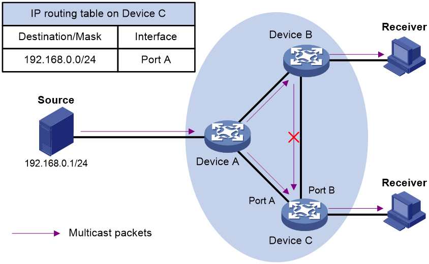
As shown in Figure 1, assume that unicast routes are available on the network, MBGP is not configured, and no static multicast routes have been configured on Device C. Multicast packets travel along the SPT from the multicast source to the receivers. The multicast forwarding table on Device C contains the (S, G) entry, with Port A as the incoming interface.
· If a multicast packet arrives at Device C on Port A, the receiving interface is the incoming interface of the (S, G) entry. Device C forwards the packet out of all outgoing interfaces.
· If a multicast packet arrives at Device C on Port B, the receiving interface is not the incoming interface of the (S, G) entry. Device C searches its unicast routing table and finds that the outgoing interface to the source (the RPF interface) is Port A. In this case, the (S, G) entry is correct, but the packet traveled along a wrong path. The packet fails the RPF check and Device C discards the packet.
Usages of static multicast routes
A static multicast route can change an RPF route or create an RPF route.
Changing an RPF route
Typically, the topology structure of a multicast network is the same as that of a unicast network, and multicast traffic follows the same transmission path as unicast traffic does. You can configure a static multicast route for a multicast source to change the RPF route. As a result, the device creates a transmission path for multicast traffic that is different from the transmission path for unicast traffic.
Figure 2 Changing an RPF route
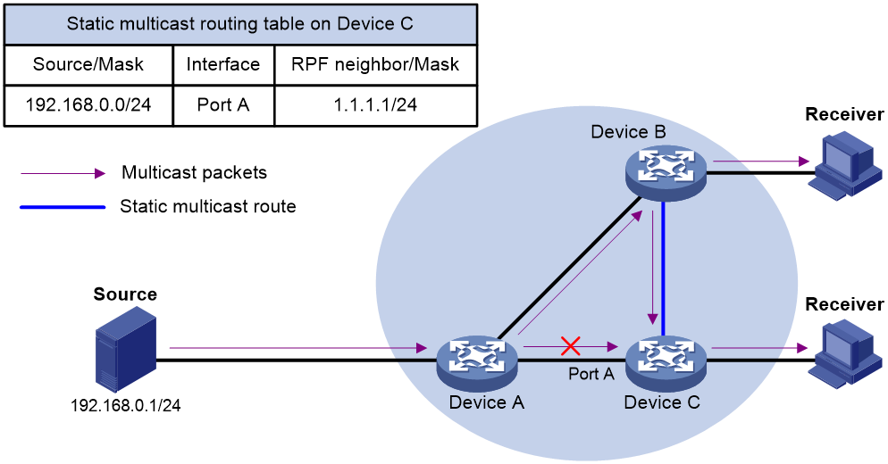
As shown in Figure 2, when no static multicast route is configured, Device C's RPF neighbor on the path back to the source is Device A. The multicast data from the source travels through Device A to Device C. You can configure a static multicast route on Device C and specify Device B as Device C's RPF neighbor on the path back to the source. The multicast data from the source travels along the path: Device A to Device B and then to Device C.
Creating an RPF route
When a unicast route is blocked, multicast forwarding might be stopped due to lack of an RPF route. You can configure a static multicast route to create an RPF route. In this way, a multicast routing entry is created to guide multicast forwarding.
Figure 3 Creating an RPF route
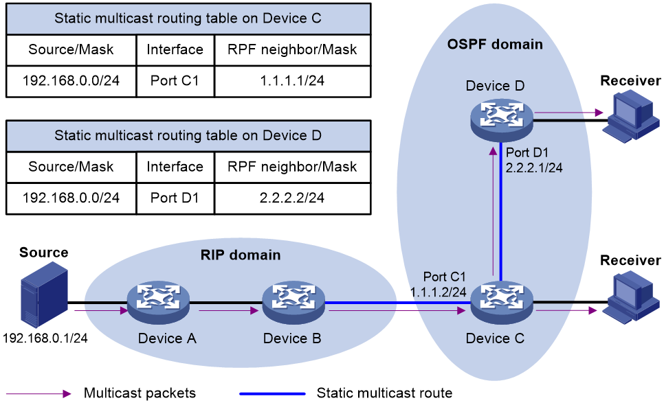
As shown in Figure 3, the RIP domain and the OSPF domain are unicast isolated from each other. For the receiver hosts in the OSPF domain to receive multicast packets from the multicast source in the RIP domain, you must configure Device C and Device D as follows:
· On Device C, configure a static multicast route for the multicast source and specify Device B as the RPF neighbor.
· On Device D, configure a static multicast route for the multicast source and specify Device C as the RPF neighbor.
Multicast forwarding across unicast subnets
Multicast data transmission over a 6to4 tunnel is not supported in the current software version.
Devices forward the multicast data from a multicast source hop by hop along the forwarding tree, but some devices might not support multicast protocols in a network. When the multicast data is forwarded to a device that does not support IP multicast, the forwarding path is blocked. In this case, you can enable multicast forwarding across two unicast subnets by establishing a tunnel between the devices at the edges of the two unicast subnets.
Figure 4 Multicast data transmission through a tunnel
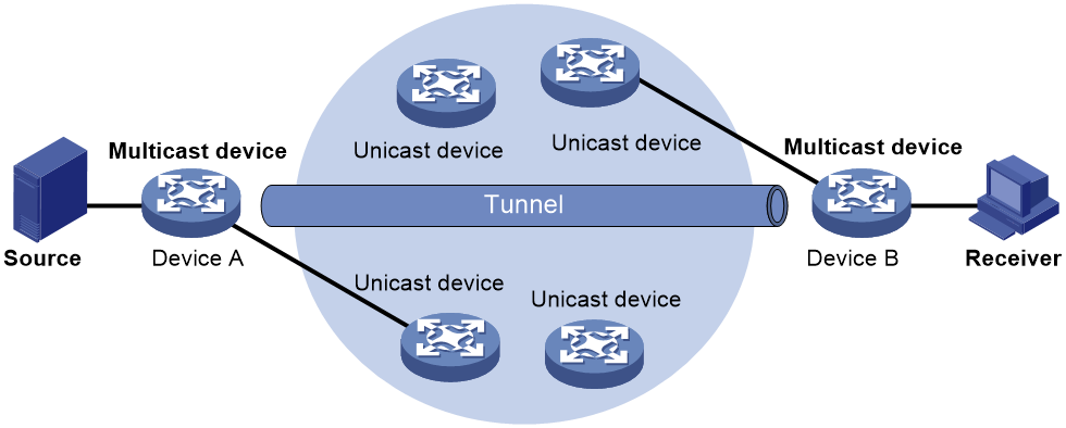
As shown in Figure 4, a tunnel is established between Device A and Device B. Device A encapsulates the multicast data in unicast IP packets, and forwards them to Device B across the tunnel through unicast devices. Then, Device B strips off the unicast IP header and continues to forward the multicast data to the receiver.
To use this tunnel only for multicast traffic, configure the tunnel as the outgoing interface only for multicast routes.
Mtrace
Mtrace is a traceroute facility used to trace the path along which multicast group data travels from a source to a destination.
Device roles
Mtrace includes the following roles:
· Last-hop router (LHR)—An LHR is a router that has a multicast-enabled interface on the same subnet as the destination and can forward specific multicast data to the subnet.
· First-hop router (FHR)—An FHR is a router that is directly connected to the multicast source.
· Client—A client is a router that initiates an mtrace.
Process
The mtrace process is as follows:
1. The client sends an mtrace Query message (with a hops field indicating the maximum number of hops to trace) to the destination.
2. The LHR turns the received Query message to an mtrace Request message by adding local forwarding information and sends the Request message to the upstream neighbor.
3. Each router along the traced path adds its local forwarding information to the received Request message and sends the Request message to its upstream neighbor.
4. The FHR adds its local forwarding information to the received Request message. Then, it turns the Request message to an mtrace Reply message and sends the Reply message to the client.
5. The client interprets forwarding information in the Reply message and displays the information.
If the client does not receive a Reply message within the waiting time, the client initiates a hop-by-hop trace to determine which device on the path encountered an error. It sends a Query message with the hops field set to 1 and waits for a Reply message. If it does not receive a Reply message within the waiting time, the client determines that this hop encountered an error. If the client receives a Reply message within the waiting time, it sends a Query message with the hops field value increased by 1 and waits for a Reply message. This process continues until the client does not receive a Reply message within the waiting time any more.
Multicast routing and forwarding diagnostic troubleshooting
This feature identifies whether the multicast module is running correctly and helps troubleshoot multicast routing entry establishment failures. For more information about this feature, see diagnostic troubleshooting in Intelligent Operations Configuration Guide.
Restrictions and guidelines: Multicast routing and forwarding configuration
The device can route and forward multicast data only through the primary IP addresses of interfaces, rather than their secondary addresses or unnumbered IP addresses. For more information about primary and secondary IP addresses, and IP unnumbered, see Layer 3—IP Services Configuration Guide.
Multicast routing and forwarding tasks at a glance
To configure multicast routing and forwarding, perform the following tasks:
1. Enabling IP multicast routing
2. (Optional.) Configuring static multicast routes
3. (Optional.) Specifying the longest prefix match principle
4. (Optional.) Configuring multicast load splitting
5. (Optional.) Configuring an IPv4 multicast flow policy
6. (Optional.) Configuring a multicast forwarding boundary
7. (Optional.) Using mtrace to trace a multicast path
8. (Optional.) Setting the maximum number of cached unknown multicast packets
Prerequisites for multicast routing and forwarding
Before you configure multicast routing and forwarding, configure a unicast routing protocol so that all devices in the domain can interoperate at the network layer.
Enabling IP multicast routing
About this task
Enable IP multicast routing before you configure any Layer 3 multicast functionality on the public network or VPN instance.
Procedure
1. Enter system view.
system-view
2. Enable IP multicast routing and enter MRIB view.
multicast routing [ vpn-instance vpn-instance-name ]
By default, IP multicast routing is disabled.
Configuring static multicast routes
About this task
To configure a static multicast route for a multicast source, you can specify an RPF interface or an RPF neighbor for the multicast traffic from that source.
Restrictions and guidelines
Static multicast routes take effect only on the multicast devices on which they are configured, and will not be advertised throughout the network or redistributed to other devices.
Procedure
1. Enter system view.
system-view
2. Configure a static multicast route.
ip rpf-route-static [ vpn-instance vpn-instance-name ] source-address { mask-length | mask } { rpf-nbr-address | interface-type interface-number } [ preference preference ] [ description text ]
3. (Optional.) Delete all static multicast routes.
delete ip rpf-route-static [ vpn-instance vpn-instance-name ]
You can use the undo ip rpf-route-static command to delete a specific static multicast route or use the delete ip rpf-route-static command to delete all static multicast routes.
Specifying the longest prefix match principle
About this task
You can enable the device to use the longest prefix match principle for RPF route selection. For more information about RPF route selection, see "RPF check process."
Procedure
1. Enter system view.
system-view
2. Enter MRIB view.
multicast routing [ vpn-instance vpn-instance-name ]
3. Specify the longest prefix match principle.
longest-match
By default, the route preference principle is used.
Configuring multicast load splitting
About this task
You can enable the device to split multiple data flows on a per-source basis or on a per-source-and-group basis. This optimizes the traffic delivery.
Restrictions and guidelines
This feature does not take effect on BIDIR-PIM.
Procedure
1. Enter system view.
system-view
2. Enter MRIB view.
multicast routing [ vpn-instance vpn-instance-name ]
3. Configure multicast load splitting.
load-splitting { balance-ecmp | balance-ucmp | ecmp | flow-ucmp | source | source-group | ucmp }
By default, multicast load splitting is disabled.
Configuring an IPv4 multicast flow policy
About this task
You can configure the estimated bandwidth for matching multicast flows through an IPv4 multicast flow policy on a downstream device if the following conditions exist:
· ECMP routes between the downstream device and an upstream device.
· The multicast load-splitting mode is flow-ucmp.
When the downstream device selects an incoming interface on the upstream device, it selects the link with the smallest bandwidth usage calculated based on the estimated bandwidth. If two links have the same bandwidth usage, the link with the higher next-hop IP address is selected.
The bandwidth usage is calculated according to the following formula: Bandwidth usage = (Used bandwidth+Estimated bandwidth)/(Total interface bandwidth x (1–Unicast reserved bandwidth)).
· The estimated bandwidth is configured by the bandwidth command in IPv4 multicast flow policy view.
· The total interface bandwidth is configured by the bandwidth command in interface view.
· The unicast reserved bandwidth is configured by the flow-ucmp unicast reserve-bandwidth or multicast flow-ucmp unicast reserve-bandwidth command.
Restrictions and guidelines for configuring an IPv4 multicast flow policy
For this feature to take effect, you must configure the multicast load-splitting mode as flow-ucmp.
Adding, deleting, or modifying an IPv4 multicast flow policy does not affect the link selection results of existing multicast flows and affects link selection for only new multicast flows. Before configuring the multicast load-splitting mode as flow-ucmp, you must plan the configuration of an IPv4 multicast flow policy and the unicast reserved bandwidth configuration.
The change of link bandwidth and the change in the number of ECMP routes do not affect the route selection of existing multicast flows.
This feature does not affect multicast source-side link selection, link selection in PIM-DM, RPT link selection in PIM-SM, or local RP link selection.
If both IPv4 and IPv6 multicast flows exist in the network, increase the unicast reserved bandwidth as needed to avoid congestion.
Creating an IPv4 multicast flow policy
1. Enter system view.
system-view
2. Enter MRIB view.
multicast routing [ vpn-instance vpn-instance-name ]
3. Create an IPv4 multicast flow policy.
¡ Create a custom IPv4 multicast flow policy.
flow-policy name policy-name
¡ Create the default IPv4 multicast flow policy.
flow-policy default
Configuring the multicast group range
About this task
Perform this task to configure a multicast group range in which an IPv4 multicast flow policy takes effect. If a multicast group matches the ACL specified in an IPv4 multicast flow policy, the estimated bandwidth configured in the policy is used for the multicast flows of the multicast group.
Restrictions and guidelines
This feature is not supported by the default IPv4 multicast flow policy.
Procedure
1. Enter system view.
system-view
2. Enter MRIB view.
multicast routing [ vpn-instance vpn-instance-name ]
3. Enter IPv4 multicast flow policy view.
flow-policy { default | name policy-name }
4. Configure the multicast group range.
acl { ipv4-acl-number | name ipv4-acl-name }
By default, an IPv4 multicast flow policy does not take effect on any multicast groups.
Configuring the estimated bandwidth
About this task
The estimated bandwidth is selected for IPv4 multicast flows as follows:
1. If the multicast group of an IPv4 multicast flow matches the ACL specified in a custom IPv4 multicast flow policy, the estimated bandwidth configured in the policy is selected for the multicast flow.
2. If the multicast group of an IPv4 multicast flow does not match an ACL in any custom IPv4 multicast flow policy, the estimated bandwidth configured in the default policy is selected for the multicast flow.
3. If the default policy is not created or the estimated bandwidth is not configured in the default policy, the estimated bandwidth for the multicast flow is 0.
Procedure
1. Enter system view.
system-view
2. Enter MRIB view.
multicast routing [ vpn-instance vpn-instance-name ]
3. Enter IPv4 multicast flow policy view.
flow-policy { default | name policy-name }
4. Configure the estimated bandwidth.
bandwidth bandwidth { gbps | kbps | mbps }
By default, the estimated bandwidth is 0.
Configuring the IPv4 unicast reserved bandwidth percentage
About this task
Perform this task when IPv4 unicast traffic and IPv4 multicast traffic coexist in the network. The available bandwidth for multicast traffic is calculated based on the total interface bandwidth and the configured IPv4 unicast reserved bandwidth percentage. For example, if the total interface bandwidth is 100 kbps and the unicast reserved bandwidth percentage is 20% (20 kbps), the available bandwidth for multicast traffic is 80 kbps.
Restrictions and guidelines
For this feature to take effect, you must configure the multicast load-splitting mode as flow-ucmp.
The flow-ucmp unicast reserve-bandwidth command takes effect on all interfaces, and the multicast flow-ucmp unicast reserve-bandwidth command takes effect only on the current interface. If you execute both commands, the latter has higher priority.
Setting the global IPv4 unicast reserved bandwidth percentage
1. Enter system view.
system-view
2. Enter MRIB view.
multicast routing [ vpn-instance vpn-instance-name ]
3. Set the global IPv4 unicast reserved bandwidth percentage.
flow-ucmp unicast reserve-bandwidth percentage
By default, the global IPv4 unicast reserved bandwidth percentage is not set.
Setting the IPv4 unicast reserved bandwidth percentage on an interface
1. Enter system view.
system-view
2. Enter interface view.
interface interface-type interface-number
3. Set the IPv4 unicast reserved bandwidth percentage on the interface.
multicast flow-ucmp unicast reserve-bandwidth percentage
By default, the IPv4 unicast reserved bandwidth percentage is not set on an interface.
Configuring a multicast forwarding boundary
About this task
You can configure an interface as a multicast forwarding boundary for a multicast group range. The interface cannot receive or forward multicast packets for the group range.
Restrictions and guidelines
You do not need to enable IP multicast before this configuration.
Procedure
system-view
2. Enter interface view.
interface interface-type interface-number
3. Configure the interface as a multicast forwarding boundary for a multicast group range.
multicast boundary group-address { mask-length | mask }
By default, an interface is not a multicast forwarding boundary.
Using mtrace to trace a multicast path
Using mtrace1 to trace a multicast path
To use mtrace version 1 (mtrace1) to trace a multicast path, execute the following command in any view:
mtrace [ v1 ] [ vpn-instance vpn-instance-name ] { source-address | group-address } * [ destination address ] [ verbose ]
Using mtrace2 to trace a multicast path
Restrictions and guidelines
For successful mtrace, do not specify a UDP port number used by other modules.
You must specify the same UDP port number on all devices on the traced path.
Procedure
1. Enter system view.
system-view
2. (Optional.) Specify the UDP port number used by mtrace.
mtrace-service port number
By default, mtrace uses UDP port number 10240.
3. Use mtrace version 2 (mtrace2) to trace a multicast path.
mtrace v2 [ vpn-instance vpn-instance-name ] { source-address | group-address } * [ destination address | port number | wait-time time | max-hop count ] * [ verbose ]
Execute this command in any view.
The UDP port number specified in this command must be the same as that specified in the mtrace-service port command.
Setting the maximum number of cached unknown multicast packets
About this task
The device caches a multicast packet for a period of time if no matching multicast forwarding entry is found for the packet. If a multicast forwarding entry is established for the packet within the time period, the device forwards the packet. This mechanism prevents the device from mistakenly dropping multicast packets when the multicast forwarding entries for these packets are to be established.
You can set the maximum number of unknown multicast packets that can be cached for an (S, G) entry, in total, or both.
Restrictions and guidelines
As a best practice, set the value in the multicast forwarding-table cache-unknown total command to be far greater than the value in the multicast forwarding-table cache-unknown per-entry command.
Procedure
1. Enter system view.
system-view
2. Set the maximum number of unknown multicast packets that can be cached for an (S, G) entry.
multicast forwarding-table cache-unknown per-entry per-entry-limit
By default, the device can cache only one unknown multicast packet for an (S, G) entry.
3. Set the maximum number of unknown multicast packets that can be cached in total.
multicast forwarding-table cache-unknown total total-limit
By default, the device can cache 1024 unknown multicast packets in total.
Verifying and maintaining multicast routing and forwarding
Verifying multicast routing and forwarding configuration and running status
Perform display tasks in any view.
· Display multicast boundary information.
display multicast [ vpn-instance vpn-instance-name ] boundary [ group-address [ mask-length | mask ] ] [ interface interface-type interface-number ]
· Display DF information.
display multicast [ vpn-instance vpn-instance-name ] forwarding df-info [ rp-address ] [ verbose ] [ slot slot-number ]
· Display information about the interfaces maintained by the MRIB.
display mrib [ vpn-instance vpn-instance-name ] interface [ interface-type interface-number ]
· Display RPF information for a multicast source.
display multicast [ vpn-instance vpn-instance-name ] rpf-info source-address [ group-address ]
· Display link selection information for IPv4 multicast flow policies.
display multicast [ vpn-instance vpn-instance-name ] flow-policy info [ interface interface-type interface-number | source source-address | group group-address | policy { default | name policy-name } ] *
Displaying multicast routing entries and multicast forwarding entries
Displaying multicast routing entries
Perform display tasks in any view.
· Display multicast routing entries.
display multicast [ vpn-instance vpn-instance-name ] routing-table [ source-address [ mask { mask-length | mask } ] | group-address [ mask { mask-length | mask } ] | incoming-interface interface-type interface-number | outgoing-interface { exclude | include | match } interface-type interface-number ] *
· Display static multicast routing entries.
display multicast[ vpn-instance vpn-instance-name ] routing-table static [ source-address { mask-length | mask } ]
Displaying multicast forwarding entries
Perform display tasks in any view.
· Display multicast forwarding entries.
display multicast [ vpn-instance vpn-instance-name ] forwarding-table [ source-address [ mask { mask-length | mask } ] | group-address [ mask { mask-length | mask } ] | incoming-interface interface-type interface-number | outgoing-interface { exclude | include | match } interface-type interface-number | slot slot-number | statistics ] *
· Display multicast fast forwarding entries.
display multicast [ vpn-instance vpn-instance-name ] fast-forwarding cache [ source-address | group-address ] * [ slot slot-number ]
· Display information about the DF list in the multicast forwarding table.
display multicast [ vpn-instance vpn-instance-name ] forwarding-table df-list [ group-address ] [ verbose ] [ slot slot-number ]
Clearing multicast routing entries and multicast forwarding entries
Restrictions and guidelines
The reset commands might cause multicast data transmission failures.
When you clear a multicast routing entry, the associated multicast forwarding entry is also cleared.
When you clear a multicast forwarding entry, the associated multicast routing entry is also cleared.
Procedure
Perform clear tasks in user view.
· Clear multicast forwarding entries.
reset multicast [ vpn-instance vpn-instance-name ] forwarding-table { { source-address [ mask { mask-length | mask } ] | group-address [ mask { mask-length | mask } ] | incoming-interface { interface-type interface-number } } * | all }
· Clear multicast fast forwarding entries.
reset multicast [ vpn-instance vpn-instance-name ] fast-forwarding cache { { source-address | group-address } * | all } [ slot slot-number ]
· Clear multicast routing entries.
reset multicast [ vpn-instance vpn-instance-name ] routing-table { { source-address [ mask { mask-length | mask } ] | group-address [ mask { mask-length | mask } ] | incoming-interface interface-type interface-number } * | all }
Displaying and clearing statistics for multicast forwarding events
To display statistics for multicast forwarding events, execute the following command in any view:
display multicast [ vpn-instance vpn-instance-name ] forwarding event [ slot slot-number]
To clear statistics for multicast forwarding events, execute the following command in user view:
reset multicast [ vpn-instance vpn-instance-name ] forwarding event
Multicast routing and forwarding configuration examples
Example: Changing an RPF route
Network configuration
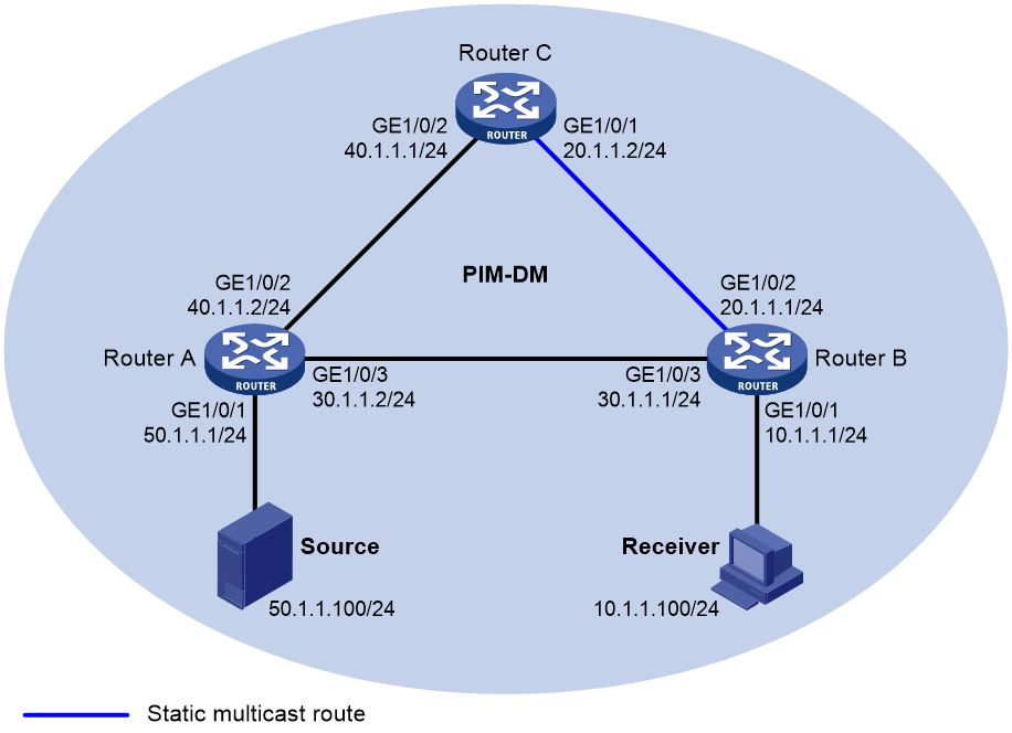
As shown in Figure 5:
· PIM-DM runs on the network.
· All routers on the network support multicast.
· Router A, Router B, and Router C run OSPF.
· Typically, the receiver host can receive the multicast data from the source through the path: Router A to Router B, which is the same as the unicast route.
Configure the routers so that the multicast data from the source travels to the receiver along the following path: Router A to Router C to Router B. This path is different from the unicast route.
Procedure
1. Assign an IP address and subnet mask for each interface, as shown in Figure 5. (Details not shown.)
2. Configure OSPF on the routers in the PIM-DM domain. (Details not shown.)
3. Enable IP multicast routing, and enable IGMP and PIM-DM:
# On Router B, enable IP multicast routing.
<RouterB> system-view
[RouterB] multicast routing
[RouterB-mrib] quit
# Enable IGMP on the receiver-side interface GigabitEthernet 1/0/1.
[RouterB] interface gigabitethernet 1/0/1
[RouterB-GigabitEthernet1/0/1] igmp enable
[RouterB-GigabitEthernet1/0/1] quit
# Enable PIM-DM on the other interfaces.
[RouterB] interface gigabitethernet 1/0/2
[RouterB-GigabitEthernet1/0/2] pim dm
[RouterB-GigabitEthernet1/0/2] quit
[RouterB] interface gigabitethernet 1/0/3
[RouterB-GigabitEthernet1/0/3] pim dm
[RouterB-GigabitEthernet1/0/3] quit
# On Router A, enable IP multicast routing.
<RouterA> system-view
[RouterA] multicast routing
[RouterA-mrib] quit
# Enable PIM-DM on each interface.
[RouterA] interface gigabitethernet 1/0/1
[RouterA-GigabitEthernet1/0/1] pim dm
[RouterA-GigabitEthernet1/0/1] quit
[RouterA] interface gigabitethernet 1/0/2
[RouterA-GigabitEthernet1/0/2] pim dm
[RouterA-GigabitEthernet1/0/2] quit
[RouterA] interface gigabitethernet 1/0/3
[RouterA-GigabitEthernet1/0/3] pim dm
[RouterA-GigabitEthernet1/0/3] quit
# Enable IP multicast routing and PIM-DM on Router C in the same way Router A is configured. (Details not shown.)
4. Display RPF information for the source on Router B.
[RouterB] display multicast rpf-info 50.1.1.100
RPF information about source 50.1.1.100:
RPF interface: GigabitEthernet1/0/3, RPF neighbor: 30.1.1.2
Referenced route/mask: 50.1.1.0/24
Referenced route type: igp
Route selection rule: preference-preferred
Load splitting rule: disable
The output shows that the current RPF route on Router B is contributed by a unicast routing protocol and the RPF neighbor is Router A.
5. On Router B, configure a static multicast route to the source and specify Router C as the RPF neighbor.
[RouterB] ip rpf-route-static 50.1.1.0 24 20.1.1.2
Verifying the configuration
# Display RPF information for the source on Router B.
[RouterB] display multicast rpf-info 50.1.1.100
RPF information about source 50.1.1.100:
RPF interface: GigabitEthernet1/0/2, RPF neighbor: 20.1.1.2
Referenced route/mask: 50.1.1.0/24
Referenced route type: multicast static
Route selection rule: preference-preferred
Load splitting rule: disable
The output shows the following information:
· The RPF route on Router B is the configured static multicast route.
· The RPF neighbor of Router B is Router C.
Example: Creating an RPF route
Network configuration
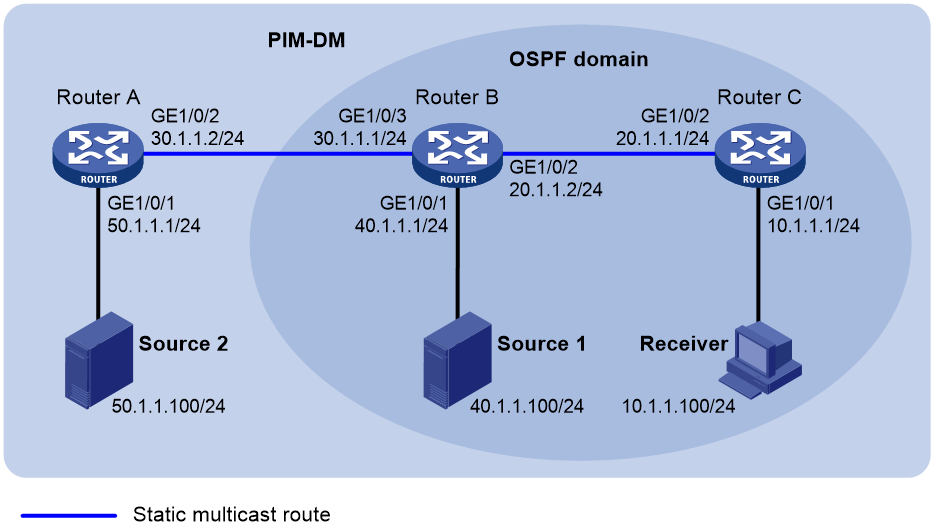
As shown in Figure 6:
· PIM-DM runs on the network.
· All routers on the network support IP multicast.
· Router B and Router C run OSPF, and have no unicast routes to Router A.
· Typically, the receiver host receives the multicast data from Source 1 in the OSPF domain.
Configure the routers so that the receiver host can receive multicast data from Source 2, which is outside the OSPF domain.
Procedure
1. Assign an IP address and subnet mask for each interface, as shown in Figure 6. (Details not shown.)
2. Configure OSPF on Router B and Router C. (Details not shown.)
3. Enable IP multicast routing, and enable IGMP and PIM-DM:
# On Router C, enable IP multicast routing.
<RouterC> system-view
[RouterC] multicast routing
[RouterC-mrib] quit
# Enable IGMP on the receiver-side interface GigabitEthernet 1/0/1.
[RouterC] interface gigabitethernet 1/0/1
[RouterC-GigabitEthernet1/0/1] igmp enable
[RouterC-GigabitEthernet1/0/1] quit
# Enable PIM-DM on GigabitEthernet 1/0/2.
[RouterC] interface gigabitethernet 1/0/2
[RouterC-GigabitEthernet1/0/2] pim dm
[RouterC-GigabitEthernet1/0/2] quit
# On Router A, enable IP multicast routing.
<RouterA> system-view
[RouterA] multicast routing
[RouterA-mrib] quit
# Enable PIM-DM on each interface.
[RouterA] interface gigabitethernet 1/0/1
[RouterA-GigabitEthernet1/0/1] pim dm
[RouterA-GigabitEthernet1/0/1] quit
[RouterA] interface gigabitethernet 1/0/2
[RouterA-GigabitEthernet1/0/2] pim dm
[RouterA-GigabitEthernet1/0/2] quit
# Enable IP multicast routing and PIM-DM on Router B in the same way Router A is configured. (Details not shown.)
4. Display RPF information for Source 2 on Router B and Router C.
[RouterB] display multicast rpf-info 50.1.1.100
[RouterC] display multicast rpf-info 50.1.1.100
No output is displayed because no RPF routes to Source 2 exist on Router B and Router C.
5. Configure a static multicast route:
# Configure a static multicast route on Router B and specify Router A as its RPF neighbor to Source 2.
[RouterB] ip rpf-route-static 50.1.1.0 24 30.1.1.2
# Configure a static multicast route on Router C and specify Router B as its RPF neighbor to Source 2.
[RouterC] ip rpf-route-static 50.1.1.0 24 20.1.1.2
Verifying the configuration
# Display RPF information for Source 2 on Router B.
[RouterB] display multicast rpf-info 50.1.1.100
RPF information about source 50.1.1.100:
RPF interface: GigabitEthernet1/0/3, RPF neighbor: 30.1.1.2
Referenced route/mask: 50.1.1.0/24
Referenced route type: multicast static
Route selection rule: preference-preferred
Load splitting rule: disable
# Display RPF information for Source 2 on Router C.
[RouterC] display multicast rpf-info 50.1.1.100
RPF information about source 50.1.1.100:
RPF interface: GigabitEthernet1/0/2, RPF neighbor: 20.1.1.2
Referenced route/mask: 50.1.1.0/24
Referenced route type: multicast static
Route selection rule: preference-preferred
Load splitting rule: disable
The output shows that the RPF routes to Source 2 exist on Router B and Router C. These RPF routes are the configured static multicast routes.
Troubleshooting multicast routing and forwarding
Static multicast route failure
Symptom
No dynamic routing protocol is enabled on the routers, and the physical status and link layer status of interfaces are both up, but the static multicast route fails.
Solution
To resolve the problem:
1. Use the display multicast routing-table static command to display information about static multicast routes. Verify that the static multicast route has been correctly configured and that the route entry exists in the static multicast routing table.
2. Check the type of interface that connects the static multicast route to the RPF neighbor. If the interface is not a point-to-point interface, be sure to specify the address for the RPF neighbor.
3. If the problem persists, contact H3C Support.