- Table of Contents
- Related Documents
-
| Title | Size | Download |
|---|---|---|
| 02-GRE over IPsec Configuration Examples | 94.56 KB |
GRE over IPsec Configuration Examples
Copyright © 2024 New H3C Technologies Co., Ltd. All rights reserved.
No part of this manual may be reproduced or transmitted in any form or by any means without prior written consent of New H3C Technologies Co., Ltd.
Except for the trademarks of New H3C Technologies Co., Ltd., any trademarks that may be mentioned in this document are the property of their respective owners.
The information in this document is subject to change without notice.
Introduction
The following information provides configuration examples for the GRE over IPsec feature of the router.
Prerequisites
The following information applies to Comware 7-based routers. Procedures and information in the examples might be slightly different depending on the software or hardware version of the routers.
The configuration examples were created and verified in a lab environment, and all the devices were started with the factory default configuration. When you are working on a live network, make sure you understand the potential impact of every command on your network.
The following information is provided based on the assumption that you have basic knowledge of IPsec.
Example: Configuring GRE over IPsec
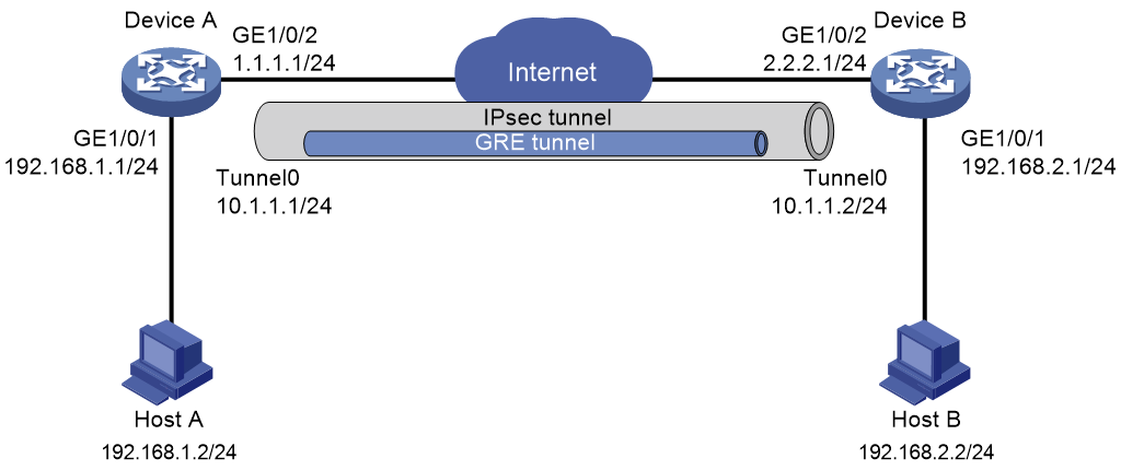
Network configuration
As shown in Figure 1, Device A and Device B transmit data to each other through a GRE tunnel. Use IPsec to encrypt the data passing through the GRE tunnel.
Analysis
· To encrypt the data encapsulated by GRE with IPsec, you must apply the IPsec policy on the physical interface connected to the peer device, and configure the source and destination addresses in the ACL as the physical interface addresses on each device.
· To use IPsec to protect the entire GRE tunnel, the interface applied with the IPsec policy and the GRE tunnel source interface and destination interface must be the same interface.
Restrictions and guidelines
Procedures
Configuring Device A
1. Configure IP addresses for interfaces.
# Configure an IP address for interface GigabitEthernet 1/0/1.
<DeviceA> system-view
[DeviceA] interface gigabitethernet 1/0/1
[DeviceA-GigabitEthernet1/0/1] ip address 192.168.1.1 255.255.255.0
[DeviceA-GigabitEthernet1/0/1] quit
# Configure an IP address for interface GigabitEthernet 1/0/2.
[DeviceA] interface gigabitethernet 1/0/2
[DeviceA-GigabitEthernet1/0/2] ip address 1.1.1.1 255.255.255.0
[DeviceA-GigabitEthernet1/0/2] quit
2. Configure the GRE tunnel:
# Create tunnel interface Tunnel 0, and specify the tunnel mode as GRE/IPv4.
[DeviceA] interface tunnel 0 mode gre
# Assign an IP address to interface Tunnel 0.
[DeviceA-Tunnel0] ip address 10.1.1.1 255.255.255.0
# Configure the source address of interface Tunnel 0 as the IP address of GigabitEthernet 1/0/2 on Device A.
[DeviceA-Tunnel0] source 1.1.1.1
# Configure the destination address of interface Tunnel 0 as the IP address of GigabitEthernet 1/0/2 on Device B.
[DeviceA-Tunnel0] destination 2.2.2.1
[DeviceA-Tunnel0] quit
3. Configure an ACL:
# Configure ACL 3000 to identify the traffic to be protected.
[DeviceA] acl number 3000
[DeviceA-acl-adv-3000] rule 0 permit gre source 1.1.1.1 0 destination 2.2.2.1 0
[DeviceA-acl-adv-3000] quit
4. Configure a static route.
# Configure a static route from Device A through interface Tunnel 0 to the subnet where Host B resides.
[DeviceA] ip route-static 192.168.2.1 255.255.255.0 tunnel 0
5. Configure the IPsec VPN:
# Create an IKE keychain.
[DeviceA] ike keychain keychain1
[DeviceA-ike-keychain-keychain1] pre-shared-key address 2.2.2.1 255.255.255.0 key simple 123456TESTplat&!
[DeviceA-ike-keychain-keychain1] quit
# Create an IPsec transform set.
[DeviceA] ipsec transform-set tran1
[DeviceA-ipsec-transform-set-tran1] esp encryption-algorithm des
[DeviceA-ipsec-transform-set-tran1] esp authentication-algorithm sha1
[DeviceA-ipsec-transform-set-tran1] quit
# Create an IKE-based IPsec policy entry. Specify the policy name as policy1 and set the sequence number to 1.
[DeviceA] ipsec policy policy1 1 isakmp
[DeviceA-ipsec-policy-isakmp-policy1-1] security acl 3000
[DeviceA-ipsec-policy-isakmp-policy1-1] remote-address 2.2.2.1
[DeviceA-ipsec-policy-isakmp-policy1-1] transform-set tran1
[DeviceA-ipsec-policy-isakmp-policy1-1] quit
Apply IPsec policy policy1 to GigabitEthernet 1/0/2.
[DeviceA] interface gigabitethernet 1/0/2
[DeviceA-GigabitEthernet1/0/2] ipsec apply policy policy1
[DeviceA-GigabitEthernet1/0/2] quit
Configuring Device B
1. Configure IP addresses for interfaces.
# Configure an IP address for interface GigabitEthernet 1/0/1.
<DeviceB> system-view
[DeviceB] interface gigabitethernet 1/0/1
[DeviceB-GigabitEthernet1/0/1] ip address 192.168.2.1 255.255.255.0
[DeviceB-GigabitEthernet1/0/1] quit
# Configure an IP address for interface GigabitEthernet1/0/2.
[DeviceB] interface gigabitethernet 1/0/2
[DeviceB-GigabitEthernet1/0/2] ip address 2.2.2.1 255.255.255.0
[DeviceB-GigabitEthernet1/0/2] quit
2. Configure the GRE tunnel:
# Create tunnel interface Tunnel 0, and specify the tunnel mode as GRE/IPv4.
[DeviceB] interface tunnel 0 mode gre
# Assign an IP address to Tunnel 0.
[DeviceB-Tunnel0] ip address 10.1.1.2 255.255.255.0
# Configure the source address of interface Tunnel 0 as the IP address of GigabitEthernet 1/0/2 on Device B.
[DeviceB-Tunnel0] source 2.2.2.1
# Configure the destination address of interface Tunnel 0 as the IP address of GigabitEthernet 1/0/2 on Device A.
[DeviceB-Tunnel0] destination 1.1.1.1
[DeviceB-Tunnel0] quit
3. Configure a static route.
# Configure a static route from Device B through Tunnel 0 to the subnet where Host A resides.
[DeviceB] ip route-static 192.168.1.1 255.255.255.0 tunnel 0
4. Create an ACL:
# Configure ACL 3000 to identify the traffic to be protected.
[DeviceB] acl number 3000
[DeviceB-acl-adv-3000] rule 0 permit gre source 2.2.2.1 0 destination 1.1.1.1 0
[DeviceB-acl-adv-3000] quit
5. Configure the IPsec VPN:
# Create an IKE keychain.
[DeviceB] ike keychain keychain1
[DeviceB-ike-keychain-keychain1] pre-shared-key address 1.1.1.1 255.255.255.0 key simple 123456TESTplat&!
[DeviceB-ike-keychain-keychain1] quit
# Create an IPsec transform set.
[DeviceB] ipsec transform-set tran1
[DeviceB-ipsec-transform-set-tran1] esp encryption-algorithm des
[DeviceB-ipsec-transform-set-tran1] esp authentication-algorithm sha1
[DeviceB-ipsec-transform-set-tran1] quit
# Create an IKE-based IPsec policy entry. Specify the policy name as policy1 and set the sequence number to 1.
[DeviceB] ipsec policy policy1 1 isakmp
[DeviceB-ipsec-policy-isakmp-policy1-1] security acl 3000
[DeviceB-ipsec-policy-isakmp-policy1-1] remote-address 1.1.1.1
[DeviceB-ipsec-policy-isakmp-policy1-1] transform-set tran1
[DeviceB-ipsec-policy-isakmp-policy1-1] quit
6. Apply IPsec policy policy1 to GigabitEthernet 1/0/2.
[DeviceB] interface gigabitethernet 1/0/2
[DeviceB-GigabitEthernet1/0/2] ipsec apply policy policy1
[DeviceB-GigabitEthernet1/0/2] quit
Verifying the configuration
# Initiate a connection from Host A to Host B to trigger IKE negotiation. Verify that you can successfully ping 192.168.2.2 from 192.168.1.2 after the IPsec tunnel is successfully established.
C:\Users> ping 192.168.2.2
Pinging 192.168.2.2 with 32 bytes of data:
Request timed out.
Reply from 192.168.2.2: bytes=32 time=2ms TTL=254
Reply from 192.168.2.2: bytes=32 time=2ms TTL=254
Reply from 192.168.2.2: bytes=32 time=1ms TTL=254
Ping statistics for 192.168.2.2:
Packets: Sent = 4, Received = 3, Lost = 1 (25% loss),
Approximate round trip times in milli-seconds:
Minimum = 1ms, Maximum = 2ms, Average = 1ms
# Execute the display ike sa command to view the IKE SA on Device A.
<DeviceA> display ike sa
Connection-ID Remote Flag DOI
------------------------------------------------------------------
2 2.2.2.1 RD IPSEC
Flags:
RD--READY RL--REPLACED FD-FADING
# Execute the display ipsec sa command to view IPsec SA information on Device A.
<DeviceA> display ipsec sa
-------------------------------
Interface: GigabitEthernet1/0/2
-------------------------------
-----------------------------
IPsec policy: policy1
Sequence number: 1
Mode: isakmp
-----------------------------
Tunnel id: 0
Encapsulation mode: tunnel
Perfect forward secrecy:
Path MTU: 1443
Tunnel:
local address: 1.1.1.1
remote address: 2.2.2.1
Flow:
sour addr: 1.1.1.1/255.255.255.255 port: 0 protocol: gre
dest addr: 2.2.2.1/255.255.255.255 port: 0 protocol: gre
[Inbound ESP SAs]
SPI: 2130348402 (0x7efa8972)
Transform set: ESP-ENCRYPT-DES-CBC ESP-AUTH-SHA1
SA duration (kilobytes/sec): 1843200/3600
SA remaining duration (kilobytes/sec): 1843199/3573
Max received sequence-number: 3
Anti-replay check enable: Y
Anti-replay window size: 64
UDP encapsulation used for NAT traversal: N
Status: Active
[Outbound ESP SAs]
SPI: 2811839266 (0xa7994322)
Transform set: ESP-ENCRYPT-DES-CBC ESP-AUTH-SHA1
SA duration (kilobytes/sec): 1843200/3600
SA remaining duration (kilobytes/sec): 1843199/3573
Max sent sequence-number: 3
UDP encapsulation used for NAT traversal: N
Status: Active
# Execute the display interface tunnel 0 command to view information about the traffic transmitted through the GRE tunnel on Device A.
<DeviceA> display interface tunnel 0
Tunnel0
Current state: UP
Line protocol state: UP
Description: Tunnel0 Interface
Bandwidth: 64kbps
Maximum Transmit Unit: 1476
Internet Address is 10.1.1.1/24 Primary
Tunnel source 1.1.1.1, destination 2.2.2.1
Tunnel keepalive disabled
Tunnel TTL 255
Tunnel protocol/transport GRE/IP
GRE key disabled
Checksumming of GRE packets disabled
Output queue - Urgent queuing: Size/Length/Discards 0/100/0
Output queue - Protocol queuing: Size/Length/Discards 0/500/0
Output queue - FIFO queuing: Size/Length/Discards 0/75/0
Last clearing of counters: Never
Last 300 seconds input rate: 0 bytes/sec, 0 bits/sec, 0 packets/sec
Last 300 seconds output rate: 0 bytes/sec, 0 bits/sec, 0 packets/sec
Input: 43 packets, 3480 bytes, 0 drops
Output: 45 packets, 3740 bytes, 2 drops
# Initiate a connection from Host B to Host A to verify the connectivity. (Details not shown.)
Configuration files
· Device A:
#
interface GigabitEthernet1/0/1
ip address 192.168.1.1 255.255.255.0
#
interface GigabitEthernet1/0/2
ip address 1.1.1.1 255.255.255.0
ipsec apply policy policy1
#
interface Tunnel0 mode gre
ip address 10.1.1.1 255.255.255.0
source 1.1.1.1
destination 2.2.2.1
#
ip route-static 192.168.2.1 24 Tunnel0
#
acl number 3000
rule 0 permit gre source 1.1.1.1 0 destination 2.2.2.1 0
#
ipsec transform-set tran1
esp encryption-algorithm des-cbc
esp authentication-algorithm sha1
#
ipsec policy policy1 1 isakmp
transform-set tran1
security acl 3000
remote-address 2.2.2.1
#
ike keychain keychain1
pre-shared-key address 2.2.2.1 255.255.255.0 key cipher $c$3$n6jdlYtuR+K6mijQ8
qp4hMMjV/iteA==
#
· Device B:
#
interface GigabitEthernet1/0/1
ip address 192.168.2.1 255.255.255.0
#
interface GigabitEthernet1/0/2
ip address 2.2.2.1 255.255.255.0
ipsec apply policy policy1
#
interface Tunnel0 mode gre
ip address 10.1.1.2 255.255.255.0
source 2.2.2.1
destination 1.1.1.1
#
ip route-static 192.168.1.1 24 Tunnel0
#
acl number 3000
rule 0 permit gre source 2.2.2.1 0 destination 1.1.1.1 0
#
ipsec transform-set tran1
esp encryption-algorithm des-cbc
esp authentication-algorithm sha1
#
ipsec policy policy1 1 isakmp
transform-set tran1
security acl 3000
remote-address 1.1.1.1
#
ike keychain keychain1
pre-shared-key address 1.1.1.1 255.255.255.0 key cipher $c$3$n6jdlYtuR+K6mijQ8
qp4hMMjV/iteA==
#
