- Table of Contents
- Related Documents
-
| Title | Size | Download |
|---|---|---|
| 01-Port Mapping and NAT Hairpin Configuration Examples | 191.86 KB |
Introduction
The following information describes how to configure port mapping and NAT hairpin on routers.
Port mapping and NAT hairpin enable both external users (for example, traveling employees) and internal users to access internal servers by using public addresses. To configure port mapping, navigate to the Network > NAT Settings > Port mapping page on the Web interface. To configure NAT hairpin, navigate to the Network > NAT Settings > Advanced Settings page on the Web interface.
Prerequisites
This document is not restricted to specific software or hardware versions. Procedures and information in the examples might be slightly different depending on the software or hardware version of the device.
The configuration examples were created and verified in a lab environment, and all the devices were started with the factory default configuration. When you are working on a live network, make sure you understand the potential impact of every command on your network.
The following information is provided based on the assumption that you have basic knowledge of port mapping and NAT hairpin.
Software versions used
This configuration example was created and verified on R6749P21 of the MSR3610-X1 router.
Example: Configuring port mapping and NAT hairpin
Network configuration
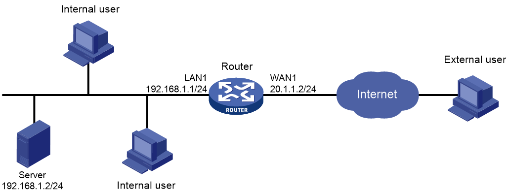
As shown in Figure 1, the router acts as the enterprise's gateway, with interface WAN1 connected to the Internet. Interface WAN1 uses fixed IP address 20.1.1.2/24 and gateway address 20.1.1.1.
Configure port mapping and NAT hairpin on the router to enable both external and internal users to access the OA server on the internal network by using the IP address and port number of interface WAN1.
The OA server uses the TCP protocol, IP address 192.168.1.2, and internal port number 80.
Procedures
Connecting the router to the Internet
In this example, select the single-WAN scenario for the router, and set the connection mode of the selected WAN interface to fixed IP.
To connect the router to the Internet:
1. Log in to the Web interface. From the navigation pane, select Network > WAN Settings.
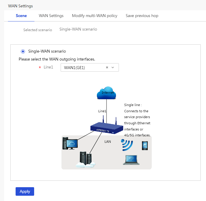
2. On the Scene tab, select Single-WAN scenario, and then click Apply.
Figure 2 Configuring the WAN scenario
3. Click the WAN Settings tab.
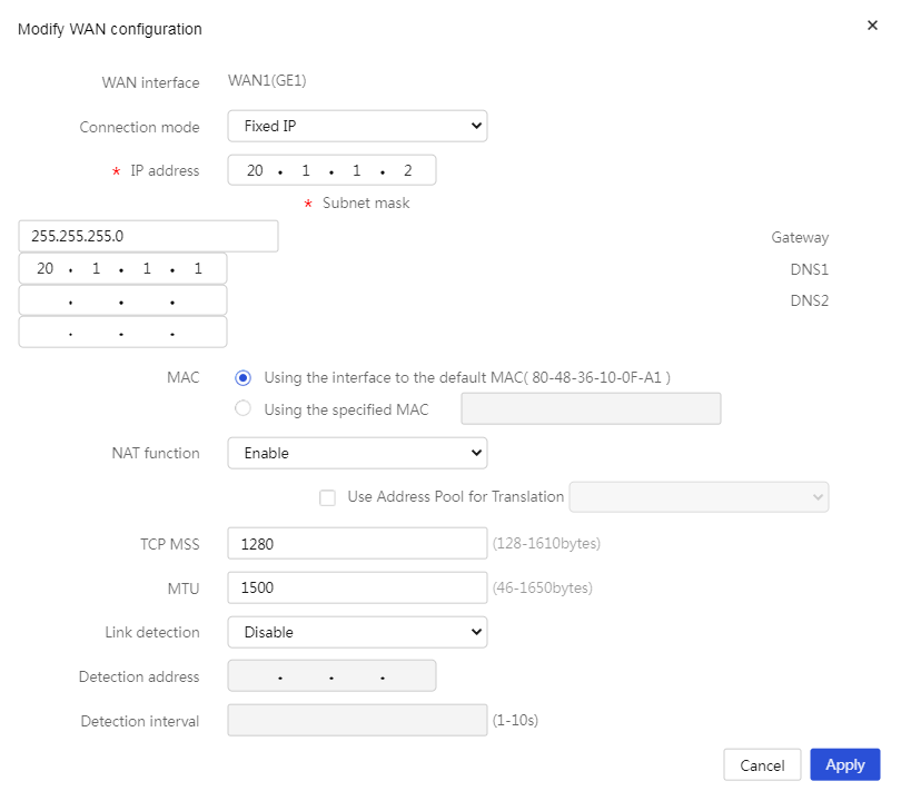
4. Click the Edit icon in the Actions column for WAN1. On the page that opens, perform the following tasks:
¡ Select Fixed IP from the Connection mode list.
¡ Enter 20.1.1.2 in the IP address field.
¡ Enter 255.255.255.0 in the Subnet mask field.
¡ Enter 20.1.1.1 in the Gateway field.
¡ Select Enable from the NAT function list.
¡ Use the default settings for the other parameters, and then click Apply.
Figure 3 Connecting interface WAN1 to the Internet
Configuring port mapping
In this example, port mapping only applies to Web services of the server. Configure the router to use a user-defined port as its global port. Make sure the start and end global port numbers are the same. As a best practice, set the port numbers to 10000 or a larger number.
To configure port mapping:
1. From the navigation pane, select Network > NAT Settings.
2. On the Port mapping tab, click Add. On the page that opens, perform the following tasks:
¡ Select WAN1(GE1) from the Interface list.
¡ Select TCP for the Protocol Type field.
¡ Select Current IP address for the Global IP address field.
¡ Select User-defined ports from the Global port number list. Set both the start and end port numbers to 10000.
¡ Enter the server IP address in the Local IP address field. In this example, enter 192.168.1.2.
¡ Set the start port number to 80 for the Local port number field.
¡ Click Apply.
Figure 4 Adding a NAT port mapping

Configuring NAT hairpin
In this example, PCs on the internal network belong to VLAN1. Assign the interface on which NAT hairpin takes effect to VLAN1.
To configure NAT hairpin:
1. From the navigation pane, select Network > NAT Settings.
2. Click the Advanced Settings tab.
3. In the NAT hairpin area, select Enable NAT hairpin function.
4. Click Apply.
Figure 5 Enabling NAT hairpin

Verifying the configuration
Verify that both external and internal users can access the website of the enterprise OA system (http://20.1.1.2:10000).
