- Table of Contents
- Related Documents
-
| Title | Size | Download |
|---|---|---|
| 03-Data buffer configuration | 85.01 KB |
Contents
Cell resources and packet resources
Configuring packet-drop alarms
Verifying and maintaining data buffers
Configuring data buffers
About data buffers
Data buffer types
Data buffers temporarily store packets.
The following data buffers are available:
· Ingress buffer—Stores incoming packets when the CPU is busy.
· Egress buffer—Stores outgoing packets when network congestion occurs.
Figure 1 shows the structure of ingress and egress buffers.
Figure 1 Data buffer structure

Cell resources and packet resources
A buffer uses the following types of resources:
· Cell resources—Store packets. The buffer uses cell resources based on packet sizes. A cell resource provides 128 bytes. The buffer allocates one cell resource to a 128-byte packet and two cell resources to a 200-byte packet.
· Packet resources—Store packet pointers. A packet pointer indicates where the packet is located in cell resources. The buffer uses one packet resource for each incoming or outgoing packet.
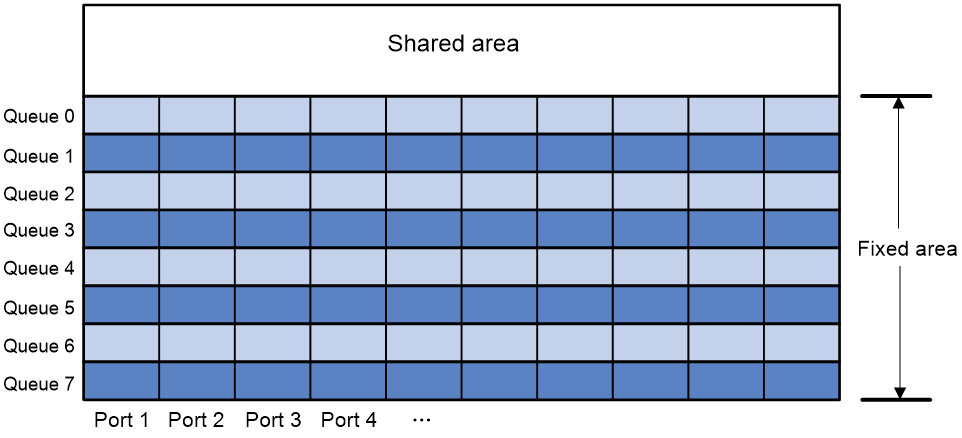
Fixed area and shared area
Each type of resources has a fixed area and a shared area.
· Fixed area—Partitioned into queues, each of which is equally divided by all the interfaces on a card, as shown in Figure 2. When congestion occurs or the CPU is busy, the following rules apply:
a. An interface first uses the relevant queues of the fixed area to store packets.
b. When a queue is full, the interface uses the corresponding queue of the shared area.
c. When the queue in the shared area is also full, the interface discards subsequent packets.
The system allocates the fixed area among queues as specified by the user. Even if a queue is not full, other queues cannot preempt its space. Similarly, the share of a queue for an interface cannot be preempted by other interfaces even if it is not full.
· Shared area—Partitioned into queues, each of which is not equally divided by the interfaces, as shown in Figure 2. The system determines the actual shared-area space for each queue according to user configuration and the number of packets actually received and sent. If a queue is not full, other queues can preempt its space.
The system puts packets received or sent on all interfaces into a queue in the order they arrive. When the queue is full, subsequent packets are dropped.
Figure 2 Fixed area and shared area
Configuring packet-drop alarms
About this task
This feature works with a network management system (such as IMC). The device periodically reports packet drop alarms for the data buffer to the network management system.
Hardware and feature compatibility
The S5580X-EI and S5580S-EI switch series do not support this feature.
Procedure
1. Enter system view.
system-view
2. Enable packet-drop alarms.
buffer packet-drop alarm enable
By default, packet-drop alarms are disabled.
3. (Optional.) Set the interval for sending packet-drop alarms.
buffer packet-drop alarm interval interval
The default setting is 5 seconds.
Verifying and maintaining data buffers
Perform all display tasks in any view.
· Display data buffer usage.
display buffer usage [ slot slot-number ]
· Display buffer usage statistics for interfaces.
display buffer usage interface [ interface-type [ interface-number ] ] [ verbose ]