- Table of Contents
- Related Documents
-
| Title | Size | Download |
|---|---|---|
| 02-Appendix | 784.46 KB |
Contents
Appendix A Server specifications
Appendix B Component specifications
DRAM DIMM rank classification label
Appendix C Common software operations
Accessing the BIOS setup utility
Configuring the memory mode from the BIOS
Obtaining the HDM management IP addresses
Appendix A Server specifications
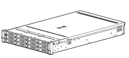
Chassis view
Technical specifications
|
Item |
Specifications |
|
Dimensions (H × W × D) |
· Without a security bezel: 87.5 × 445.4 × 748 mm (3.44 × 17.54 × 29.45 in) · With a security bezel: 87.5 × 445.4 × 769 mm (3.44 × 17.54 × 30.28 in) |
|
Max. weight |
27.33 kg (60.25 lb) |
Front panel
Front panel view
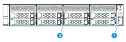
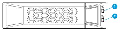
Figure 2 CSAP-SA front panel
|
(1) USB 3.0 connector |
(2) Drive cage bay for 8LFF drives |
LEDs and buttons
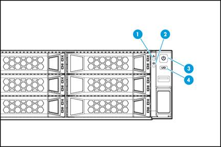
Figure 3 Front panel LEDs and buttons
|
(1) Health LED |
(2) Ethernet port LED |
|
(3) Power on/standby button and system power LED |
(4) UID button LED |
Table 1 LEDs and buttons on the front panel
|
Button/LED |
Status |
|
Health LED |
· Steady green—The system is operating correctly. · Flashing green (4 Hz)—HDM is initializing. · Flashing amber (0.5 Hz)—A predictive alarm has occurred. · Flashing amber (1 Hz)—A major alarm has occurred. · Flashing red (1 Hz)—A critical alarm has occurred. If a system alarm is present, log in to HDM to obtain more information about the system running status. |
|
Ethernet port LED |
· Steady green—A link is present on the port. · Flashing green (1 Hz)—The port is receiving or sending data. · Off—No link is present on the port. |
|
Power on/standby button and system power LED |
· Steady green—The system has started. · Flashing green (1 Hz)—The system is starting. · Steady amber—The system is in Standby state. · Off—No power is present. Possible reasons: ¡ No power source is connected. ¡ No power supplies are present. ¡ The installed power supplies are faulty. ¡ The system power cords are not connected correctly. |
|
UID button LED |
· Steady blue—UID LED is activated. The UID LED can be activated by using the following methods: ¡ Press the UID button LED. ¡ Activate the UID LED from HDM. · Flashing blue: ¡ 1 Hz—The firmware is being upgraded or the system is being managed from HDM. ¡ 4 Hz—HDM is restarting. To restart HDM, press the UID button LED for 8 seconds. · Off—UID LED is not activated. |
Ports
Table 2 Optional ports on the front panel
|
Port |
Type |
Description |
|
USB connector |
USB 3.0 |
Connects the following devices: · USB flash drive. · USB keyboard or mouse. · USB optical drive for operating system installation. |
Rear panel
Rear panel view
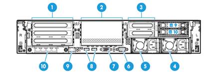
Figure 4 Rear panel components
|
(1) PCIe slots 1 through 3 from the top down (processor 1) |
|
|
(2) PCIe slots 4 through 6 from the top down (processor 2) |
|
|
(3) PCIe slots 7 and 8 from the top down (processor 2)(not supported) |
|
|
(4) Power supply 2 |
(5) Power supply 1 |
|
(6) BIOS serial port |
(7) VGA connector |
|
(8) USB 3.0 connectors |
|
|
(9) HDM dedicated network port (1 Gbps, RJ-45, default IP address 192.168.1.2/24) |
|
|
(10) 4-port mLOM network adapter |
|
LEDs
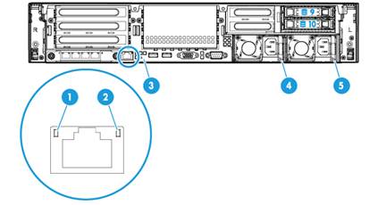
Figure 5 Rear panel LEDs
|
(1) Link LED of the Ethernet port |
(2) Activity LED of the Ethernet port |
|
(3) UID LED |
(4) Power supply 1 LED |
|
(5) Power supply 2 LED |
|
Table 3 LEDs on the rear panel
|
LED |
Status |
|
Link LED of the Ethernet port |
· Steady green—A link is present on the port. · Off—No link is present on the port. |
|
Activity LED of the Ethernet port |
· Flashing green (1 Hz)—The port is receiving or sending data. · Off—The port is not receiving or sending data. |
|
UID指示灯 |
· Steady blue—UID LED is activated. The UID LED can be activated by using the following methods: ¡ Press the UID button LED. ¡ Enable UID LED from HDM. · Flashing blue: ¡ 1 Hz—The firmware is being updated or the system is being managed by HDM. ¡ 4 Hz—HDM is restarting. To restart HDM, press the UID button LED for 8 seconds. · Off—UID LED is not activated. |
|
Power supply LED |
· Steady green—The power supply is operating correctly. · Flashing green (1 Hz)—Power is being input correctly but the system is not powered on. · Flashing green (0.33 Hz)—The power supply is in standby state and does not output power. · Steady amber—Either of the following conditions exists: ¡ The power supply is faulty. ¡ The power supply does not have power input, but the other power supply has correct power input. · Flashing amber (1 Hz)—An alarm has occurred on the power supply. · Off—No power supplies have power input, which can be caused by an incorrect power cord connection or power source shutdown. |
Ports
Table 4 Ports on the rear panel
|
Type |
Description |
|
|
HDM dedicated network port |
RJ-45 |
Establishes a network connection to manage HDM from its Web interface. |
|
USB connector |
USB 3.0 |
Connects the following devices: · USB flash drive. · USB keyboard or mouse. · USB optical drive for operating system installation. |
|
VGA connector |
DB-15 |
Connects a display terminal, such as a monitor or KVM device. |
|
BIOS serial port |
DB-9 |
The BIOS serial port is used for the following purposes: · Log in to the server when the remote network connection to the server has failed. · Establish a GSM modem or encryption lock connection. |
|
Power receptacle |
Standard single-phase |
Connects the power supply to the power source. |
System board
System board components
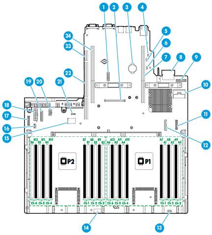
Figure 6 System board components
|
(1) TPM/TCM connector |
(2) Mezzanine storage controller connector |
|
(3) System battery |
(4) System maintenance switch 1 |
|
(5) System maintenance switch 2 |
(6) System maintenance switch 3 |
|
(7) PCIe riser connector 1 (processor 1) |
(8) mLOM network adapter connector (coming with a 4-port mLOM Ethernet adapter) |
|
(9) Network adapter NCSI function connector |
(10) Mini-SAS port (×8 SATA ports) |
|
(11) Front I/O connector |
(12) Optical/SATA port |
|
(13) Diagnostic panel connector (not supported) |
(14) Front drive backplane power connector 1 |
|
(15) Dual internal USB 3.0 connectors |
(16) Front drive backplane AUX connector 2 or rear drive backplane AUX connector |
|
(17) Chassis-open alarm module, front VGA, and USB 2.0 connector |
(18) Front drive backplane power connector 2 and SATA M.2 SSD power connector |
|
(19) Front drive backplane AUX connector 1 |
(20) Rear drive backplane power connector |
|
(21) NVMe VROC module connector |
(22) PCIe riser connector 3 (processor 2) |
|
(23) Dual SD card extended module connector |
(24) PCIe riser connector 2 (processor 2) |
System maintenance switches
Use the system maintenance switches if you forget HDM username, HDM password, or BIOS password, or need to restore default BIOS settings, as described in Table 5. To identify the location of the switches on the system board, see "System board components."
Table 5 System maintenance switches
|
Item |
Description |
Remarks |
|
System maintenance switch 1 |
· Pins 1-2 jumped (default)—HDM login requires the username and password of a valid HDM user account. · Pins 2-3 jumped—HDM login requires the default username and password. |
For security purposes, jump pins 1 and 2 after you complete tasks with the default username and password as a best practice. |
|
System maintenance switch 2 |
· Pins 1-2 jumped (default)—Normal server startup. · Pins 2-3 jumped—Clears all passwords from the BIOS at server startup. |
To clear all passwords from the BIOS, jump pins 2 and 3 and then start the server. All the passwords will be cleared from the BIOS. Before the next server startup, jump pins 1 and 2 to perform a normal server startup. |
|
System maintenance switch 3 |
· Pins 1-2 jumped (default)—Normal server startup. · Pins 2-3 jumped—Restores the default BIOS settings. |
To restore the default BIOS settings, jump pins 2 and 3 for over 30 seconds and then jump pins 1 and 2 for normal server startup. |
DIMM slots
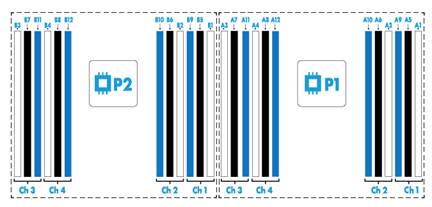
The server provides 4 DIMM channels per processor, 12 channels in total. Each channel contains one white-coded slot, one black-coded slot, and one blue-coded slot.
Figure 7 shows the physical layout of the DIMM slots on the system board. For more information about the DIMM slot population rules, see the guidelines in "Installing DIMMs."
Appendix B Component specifications
Drives
Drive numbering
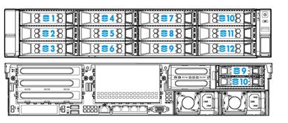
Figure 8 Front drive numbering for 8LFF drive configuration

Figure 9 Front and rear drive numbering for 12LFF+2SFF drive configuration
Drive LEDs
|
(1) Fault/UID LED |
(2) Present/Active LED |
Table 6 Drive LED description
|
Fault/UID LED status |
Present/Active LED status |
Description |
|
Steady green/Flashing green (4.0 Hz) |
A drive failure is predicted. As a best practice, replace the drive before it fails. |
|
|
Steady amber |
Steady green/Flashing green (4.0 Hz) |
The drive is faulty. Replace the drive immediately. |
|
Steady blue |
Steady green/Flashing green (4.0 Hz) |
The drive is operating correctly and is selected by the RAID controller. |
|
Off |
Flashing green (4.0 Hz) |
The drive is performing a RAID migration or rebuilding, or the system is reading or writing data to the drive. |
|
Off |
Steady green |
The drive is present but no data is being read or written to the drive. |
|
Off |
Off |
The drive is not securely installed. |
Processor
Table 7 Processor specifications
|
Model |
Base frequency (GHz) |
Power (W) |
Cores |
L3 cache (MB) |
UPIs and speed (GT/s) |
|
4110 |
2.1 |
85 |
8 |
11 |
2 ×9.6 |
|
|
NOTE: The server comes with one 4110 processor. |
DIMM
DRAM DIMM rank classification label
A DIMM rank is a set of memory chips that the system accesses while writing or reading from the memory. On a multi-rank DIMM, only one rank is accessible at a time.
To determine the rank classification of a DRAM DIMM, use the label attached to the DIMM, as shown in Figure 11.
Figure 11 DRAM DIMM rank classification label
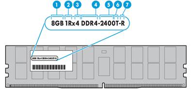
Table 8 DIMM rank classification label description
|
Callout |
Description |
Remarks |
|
1 |
Capacity |
Options include: · 8GB. · 16GB. · 32GB. |
|
2 |
Number of ranks |
Options include: · 1R— One rank. · 2R—Two ranks. · 4R—Four ranks. · 8R—Eight ranks. |
|
3 |
Data width |
Options include: · ×4—4 bits. · ×8—8 bits. |
|
4 |
DIMM generation |
Only DDR4 is supported. |
|
5 |
Data rate |
Options include: · 2133 MHz. · 2400 MHz. |
|
6 |
CAS latency |
One T equals 17 clock cycles. |
|
7 |
DIMM type |
Options include: · L—LRDIMM. · R—RDIMM. |
|
|
NOTE: The data rate of a DIMM can be displayed in DDR4-xx or PC4-xx format. In DDR4-xx format, DDR4 represents the generation and xx represents the data rate in MHz. In PC4-xx format, PC4 represents the generation and xx represents the bandwidth in MB/s. |
DIMM specifications
Table 9 DIMM specifications
|
Model |
Type |
Rank |
Capacity |
Data rate |
|
DDR4-16G-1Rx4-R |
RDIMM |
1R |
16 GB |
2666 MHz |
|
DDR4-32G-2Rx4-R |
RDIMM |
2R |
32 GB |
2666 MHz |
|
|
NOTE: The server comes with 32GB memory (2 × 16GB DIMMs). |
HDDs and SSDs
Table 10 HDD specifications
|
Model |
Capacity |
Interface type |
Port rate |
Rotation speed |
Form factor |
|
HDD-1T-SATA-6G-LFF |
1 TB |
SATA |
6 G |
7.2K |
LFF |
|
HDD-2T-SATA-6G-LFF |
2 TB |
SATA |
6 G |
7.2K |
LFF |
|
HDD-4T-SATA-6G-LFF |
4 TB |
SATA |
6 G |
7.2K |
LFF |
|
HDD-600G-SAS-12G-LFF |
600 GB |
SAS |
12 G |
10K |
LFF |
|
HDD-600G-SAS-12G-SFF |
600 GB |
SAS |
12 G |
10K |
SFF |
Table 11 SSD specifications
|
Model |
Capacity |
Interface type |
Port rate |
Form factor |
|
SSD-240G-SATA-6G-LFF-i |
240 GB |
SATA |
6G |
LFF |
|
SSD-480G-SATA-6G-LFF |
480 GB |
SATA |
6G |
LFF |
|
|
NOTE: The server comes with three HDD-4T-SATA-6G-LFF HDDs. No SSDs are provided by default. You can purchase SSDs as needed. |
Riser card
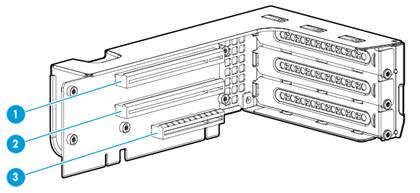
Figure 12 Riser card view
|
(1) PCIe slot 1/4 |
(2) PCIe slot 2/5 |
(3) PCIe slot 3/6 |
|
|
NOTE: If a riser card can be installed on riser connector 1 or 2, the slot numbers of its PCIe slots are presented in the m/n format in this document. · The m argument represents the PCIe slot number on connector 1. · The n argument represents the PCIe slot number on connector 2. For example, PCIe slot 2/5 represents that a PCIe slot is numbered 2 or 5 when the riser card is installed on riser connector 1 or riser connector 2, respectively. |
PCIe network adapters
Table 12 PCIe network adapter specifications
|
Model |
Ports |
Port type |
Transmit rate |
Data channel bus |
Form factor |
|
NSQM1SCXGT4A |
4 |
RJ-45 |
10/100/1000 Mbps |
PCIe2.0 x4 |
LP |
|
NSQM1SCXTG2A |
2 |
SFP+ |
10 Gbps |
PCIe2.0 x8 |
LP |
|
|
NOTE: No PCIe network adapter is provided with the server. You can purchase PCIe network adapters as needed. |
Fans
Table 13 Fan specifications
|
Diameter |
Rated rotation speed |
Max air volume |
|
60 mm, single rotor |
16500 RPM |
76.16 CFM |
|
|
NOTE: The server comes with four fans. |
Power supplies
Table 14 Power supply specifications
|
Item |
800W power supply |
550W power supply |
|
Model |
PSR800-12A-A |
PSR550-12A-A |
|
Rated input voltage range |
· 100 VAC to 240 VAC @50/60Hz (10 A receptacle) · 192 VDC to 288 VDC (240 HVDC power source) |
· 100 VAC to 240 VAC @50/60Hz (10 A receptacle) · 192 VDC to 288 VDC (240 HVDC power source) |
|
Rated input current |
10.0 A Max @ 100 to 240 VAC |
8.0 A Max @ 100 to 240V AC |
|
4.0 A Max @ 240 VDC |
2.75 A Max @ 240V DC |
|
|
Max rated output power |
800 W |
550 W |
|
Efficiency @ 50% load |
94%, Platinum level |
94%, Platinum level |
|
Temperature |
· Operating temperature: 0°C to 50°C (32°F to 122°F) · Storage temperature: –40°C to +70°C (–40°F to +158°F) |
|
|
Operating humidity |
5% to 90% |
5% to 90% |
|
Maximum altitude |
5000 m (16404.20 ft) |
5000 m (16404.20 ft) |
|
Redundancy |
1+1 redundancy |
1+1 redundancy |
|
Hot swappable |
Yes |
Yes |
|
Cold backup |
Yes |
Yes |
|
|
NOTE: · The server comes with one 550 W power supply. · 1+1 redundancy and power supply hot swapping are available only when two power supplies of the same model are present. |
Appendix C Common software operations
Figures in this section are for illustration only. The software interface might differ from your screen display.
Accessing the BIOS setup utility
|
|
CAUTION: Before restarting the server, save all the data to avoid data loss. |
By default, no boot password, administrator password, and user password are configured. You can access the BIOS setup utility directly.
To access the BIOS setup utility:
1. Connect a mouse, keyboard, and monitor to the server, or launch a remote console from HDM.
2. Start or restart the server. To start or restart the server from a remote console:
¡ To
start the server from a remote console, click Power > Power On or the ![]() icon.
icon.
¡ To restart the server from a remote console, click Power > Force System Reset.
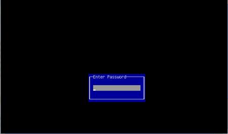
3. If the system requires a password during the start process, enter the administrator password or user password.
If you forget the administrator password or user password, power off the server, turn on system maintenance switch 2, and then power on the server. The system clears administrator and user passwords for the BIOS at the restart. For more information about system maintenance switches, see "System maintenance switches."
Figure 13 Entering the administrator password or user password
4. Press Del or Esc on the BIOS boot screen as shown in Figure 14.
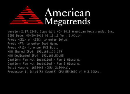
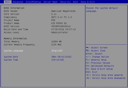
The BIOS setup screen opens as shown in Figure 15.
Configuring the memory mode from the BIOS
1. Enter the BIOS setup utility.
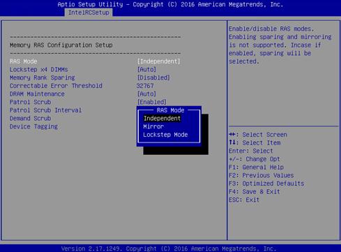
2. Access the IntelRCSetup > Memory Configuration > Memory RAS Configuration screen.
3. Select a RAS mode and then press Enter.
By default, the RAS mode is Independent.
Figure 16 Setting the RAS mode
4. Configure memory rank sparing.
By default, memory rank sparing is disabled.
You cannot enable memory rank sparing and the mirror mode at the same time. If you set the RAS mode to mirror, enabling memory rank sparing restores the default RAS mode (independent mode).
Figure 17 Configuring memory rank sparing

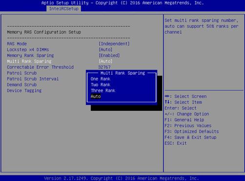
5. If you enable memory rank sparing, specify the number of spare ranks.
a. Select Multi Rank Sparing and then press Enter.
b. Select the spare rank quantity and then press Enter. Options include:
- One Rank—Uses one rank as the spare. Make sure a minimum of two ranks are available for each channel.
- Two Rank—Uses two ranks as the spares. Make sure a minimum of four ranks are available for each channel.
- Three Rank—Uses three ranks as the spares. Make sure a minimum of six ranks are available for each channel.
- Auto—Uses 50% ranks of a channel as the spares. Make sure a minimum of two ranks are available for each channel.
By default, the Auto mode is used. If the number of ranks cannot meet the requirement, the system changes the spare rank sparing value to Auto automatically.
Figure 18 Selecting the number of spare ranks
6. Press F4 to save the configuration.
Logging in to HDM
After connecting the server to the network, you can log in to HDM for the server through the HDM dedicated network port. Table 15 displays the default HDM sign-in settings. If the HDM management IP address has been changed, you can access the BIOS boot screen to obtain the IP address. For more information, see "Obtaining the HDM management IP addresses."
Table 15 Default HDM sign-in settings
|
Item |
Default setting |
|
Management IP address |
HDM dedicated network port: 192.168.1.2/24 |
|
Username, password, and domain name |
· Username: admin · Password: Password@_ · Domain name: See the label at the lower left corner of the chassis access panel |
Obtaining the HDM management IP addresses
To view HDM management IP addresses from the BIOS boot screen, make sure quiet boot is disabled from the Boot > Quiet Boot screen.
Access the BIOS boot screen as shown in Figure 14, and view the shared network port address (HDM Shared IPv4) and dedicated network port address (HDM Dedicated IPv4).
Signing in to HDM
1. Open the browser, and enter the HDM management IP address in the https://HDM_ip_address format. This section uses Internet Explorer and IP address 192.168.50.85 as an example.
2. On the security certificate page that opens, click Continue to this website (not recommended).
Figure 19 Security certificate confirmation page

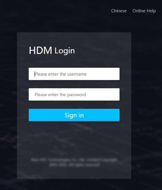
3. On the sign-in page, select an interface language as needed, enter the username and password, and then click Sign in.
The default username is admin) and the default password is Password@_.
Figure 20 HDM sign-in page
Appendix D Glossary
Table 16
|
Description |
||
|
B |
||
|
BIOS |
Basic input/output system is non-volatile firmware pre-installed in a ROM chip on a server's system board. The BIOS stores basic input/output, power-on self-test, and auto startup programs to provide the most basic hardware initialization, setup and control functionality. |
|
|
C |
||
|
CPLD |
Complex programmable logic device is an integrated circuit used to build reconfigurable digital circuits. |
|
|
H |
||
|
HDM |
Hardware Device Management is the server management control unit with which administrators can configure server settings, view component information, monitor server health status, and remotely manage the server. |
|
|
Hot swapping |
A module that supports hot swapping (a hot-swappable module) can be installed or removed while the server is running without affecting the system operation. |
|
|
K |
||
|
KVM |
A device that allows remote users to use their local video display, keyboard, and mouse to monitor and control remote servers. |
|
|
R |
||
|
RAID |
Redundant array of independent disks (RAID) is a data storage virtualization technology that combines multiple physical hard drives into a single logical unit to improve storage and security performance. |
|
|
Redundancy |
A mechanism that ensures high availability and business continuity by providing backup modules. In redundancy mode, a backup or standby module takes over when the primary module fails. |
|
|
U |
A unit of measure defined as 44.45 mm (1.75 in) in IEC 60297-1. It is used as a measurement of the overall height of racks, as well as equipment mounted in the racks. |
|
Appendix E Acronyms
|
Acronym |
Full name |
|
B |
|
|
BIOS |
Basic Input Output System |
|
C |
|
|
CD |
Compact Disk |
|
CPLD |
Complex Programmable Logic Device |
|
CPU |
Central Processing Unit |
|
D |
|
|
DIMM |
Dual Inline Memory Module |
|
DVD |
Digital Versatile Disc |
|
F |
|
|
FLOM |
|
|
G |
|
|
GPU |
Graphics Processing Unit |
|
GUI |
Graphical User Interface |
|
H |
|
|
HBA |
Host Bus Adapter |
|
HDD |
Hard Disk Drive |
|
HDM |
Hardware Device Management |
|
I |
|
|
IDC |
Internet Data Center |
|
K |
|
|
KVM |
Keyboard, Video, Mouse |
|
L |
|
|
LFF |
Large Form Factor |
|
LRDIMM |
Load Reduced Dual Inline Memory Module |
|
P |
|
|
PCIe |
Peripheral Component Interconnect Express |
|
POST |
Power-on Self Test |
|
R |
|
|
Redundant Arrays of Independent Disks |
|
|
RAS |
Reliability, Availability, Serviceability |
|
RDIMM |
Registered Dual Inline Memory Module |
|
S |
|
|
SAS |
Serial Attached Small Computer System Interface |
|
SATA |
Serial ATA |
|
SD |
Secure Digital |
|
SDDC |
Single Device Data Correction |
|
SDS |
Secure Diagnosis System |
|
SFF |
Small Form Factor |
|
SSD |
Solid State Drive |
|
T |
|
|
TCM |
Trusted Cryptography Module |
|
TPM |
Trusted Platform Module |
|
U |
|
|
UEFI |
Unified Extensible Firmware Interface |
|
UID |
Unit Identification |
|
UPS |
Uninterruptible Power Supply |
|
USB |
Universal Serial Bus |
