- Table of Contents
- Related Documents
-
| Title | Size | Download |
|---|---|---|
| 01-Text | 2.64 MB |
Installation safety recommendations
Installation site requirements
Airflow direction of the server
Temperature and humidity requirements
Equipment room height requirements
Installing or removing the server
Installing cable management brackets·
Connecting a mouse, keyboard, and monitor
Removing the server from a rack
Installing a PCIe network adapter
Powering on and powering off the server
Replacing the chassis air baffle
Removing the chassis air baffle
Installing the chassis air baffle
Replacing a PCIe network adapter
Safety information
Safety sign conventions
To avoid bodily injury or damage to the server or its components, make sure you are familiar with the safety signs on the server chassis or its components.
Table 1 Safety signs
|
Sign |
Description |
|
|
Circuit or electricity hazards are present. Only H3C authorized or professional server engineers are allowed to service, repair, or upgrade the server.
To avoid bodily injury or damage to circuits, do not open any components marked with the electrical hazard sign unless you have authorization to do so. |
|
|
Electrical hazards are present. Field servicing or repair is not allowed.
To avoid bodily injury, do not open any components with the field-servicing forbidden sign in any circumstances. |
|
|
The surface or component might be hot and present burn hazards.
To avoid being burnt, allow hot surfaces or components to cool before touching them. |
|
|
The server or component is heavy and requires more than one people to carry or move.
To avoid bodily injury or damage to hardware, do not move a heavy component alone. In addition, observe local occupational health and safety requirements and guidelines for manual material handling. |
|
|
The server is powered by multiple power supplies.
To avoid bodily injury from electrical shocks, make sure you disconnect all power supplies if you are performing offline servicing. |
Power source recommendations
Power instability or outage might cause data loss, service disruption, or damage to the server in the worst case.
To protect the server from unstable power or power outage, use uninterrupted power supplies (UPSs) to provide power for the server.
Installation safety recommendations
To avoid bodily injury or damage to the server, read the following information carefully before you operate the server.
General operating safety
To avoid bodily injury or damage to the server, follow these guidelines when you operate the server:
· Only H3C authorized or professional server engineers are allowed to install, service, repair, operate, or upgrade the server.
· Place the server on a clean, stable table or floor for servicing.
· Make sure all cables are correctly connected before you power on the server.
· To avoid being burnt, allow the server and its internal modules to cool before touching them.
Electrical safety
|
|
WARNING! If you put the server in standby mode (system power LED in amber) with the power on/standby button on the front panel, the power supplies continue to supply power to some circuits in the server. To remove all power for servicing safety, you must first press the button, wait for the system to enter standby mode, and then remove the power cords from the server. |
To avoid bodily injury or damage to the server, follow these guidelines:
· Always use the power cords that came with the server.
· Do not use the power cords that came with the server for any other devices.
· Power off the server when installing or removing any components that are not hot swappable.
Rack mounting recommendations
To avoid bodily injury or damage to the equipment, follow these guidelines when you rack mount a server:
· Mount the server in a standard 19-inch rack.
· Make sure the leveling jacks are extended to the floor and the full weight of the rack rests on the leveling jacks.
· Couple the racks together in multi-rack installations.
· Load the rack from the bottom to the top, with the heaviest hardware unit at the bottom of the rack.
· Get help to lift and stabilize the server during installation or removal, especially when the server is not fastened to the rails. As a best practice, a minimum of two people are required to safely load or unload a rack. A third person might be required to help align the server if the server is installed higher than check level.
· For rack stability, make sure only one unit is extended at a time. A rack might get unstable if more than one server unit is extended.
· Make sure the rack is stable when you operate a server in the rack.
· To maintain correct airflow and avoid thermal damage to the server, use blank panels to fill empty rack units.
ESD prevention
Electrostatic charges that build up on people and tools might damage or shorten the lifespan of the system board and electrostatic-sensitive components.
Preventing electrostatic discharge
To prevent electrostatic damage, follow these guidelines:
· Transport or store the server with the components in antistatic bags.
· Keep the electrostatic-sensitive components in separate antistatic bags until they arrive at an ESD-protected area.
· Place the components on a grounded surface before removing them from their antistatic bags.
· Avoid touching pins, leads, or circuitry.
Grounding methods to prevent electrostatic discharge
The following are grounding methods that you can use to prevent electrostatic discharge:
· Wear an ESD wrist strap and make sure it makes good skin contact and is reliably grounded.
· Take adequate personal grounding measures, including wearing antistatic clothing and static dissipative shoes.
· Use conductive field service tools.
· Use a portable field service kit with a folding static-dissipating work mat.
Cooling performance
Poor cooling performance might result from improper airflow and poor ventilation and might cause damage to the server.
To ensure good ventilation and proper airflow, follow these guidelines:
· Install blanks if the following module slots are empty:
¡ Drive bays.
¡ Fan bays.
¡ PCIe slots.
¡ Power supply slots.
· Do not block the ventilation openings in the server chassis.
· To avoid thermal damage to the server, do not operate the server for long periods in any of the following conditions:
¡ Access panel open or uninstalled.
¡ Air baffles uninstalled.
¡ PCIe slots, drive bays, fan bays, or power supply slots empty.
· If you stack devices in a rack, make sure a minimum of 2 mm (0.08 in) space is available between two vertically adjacent devices.
Battery safety
The server's system board contains a system battery, which is designed with a lifespan of 5 to 10 years.
If the server no longer automatically displays the correct date and time, you might need to replace the battery. When you replace the battery, follow these safety guidelines:
· Do not attempt to recharge the battery.
· Do not expose the battery to a temperature higher than 60°C (140°F).
· Do not disassemble, crush, puncture, short external contacts, or dispose of the battery in fire or water.
· Dispose of the battery at a designated facility. Do not throw the battery away together with other wastes.
Preparing for installation
Prepare a rack that meets the rack requirements and plan an installation site that meets the requirements for space and airflow, temperature, humidity, equipment room height, cleanliness, and grounding.
Space requirements
The cabinet for installing the server must meet the following requirements:
· A minimum clearance of 635 mm (25 in) in front of the cabinet.
· A minimum clearance of 762 mm (30 in) behind the cabinet.
· A minimum clearance of 1219 mm (47.99 in) between two adjacent cabinets.
Installation site requirements
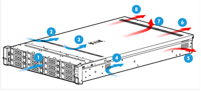
Airflow direction of the server
Figure 1 Airflow direction of the server
|
(1) to (4) Directions of the airflow into the chassis and power supplies |
|
|
(5) to (7) Direction of the airflow out of the chassis |
(8) Direction of the airflow out of the power supplies |
Temperature and humidity requirements
To ensure correct operation of the server, make sure the room temperature and humidity meet the requirements as described in Table 2.
Table 2 Temperature and humidity requirements
|
Item |
Description |
|
Temperature |
· Operating temperature: 0°C to 45°C (32°F to 113°F) · Storage temperature: –40°C to +70°C (–40°F to +158°F) |
|
Humidity |
· Operating humidity: 8% to 90%, non-condensing · Storage humidity: 5% to 95%, non-condensing |
|
Operating altitude |
–60 m to +3000 m (–196.85 ft to +9842.52 ft) The allowed maximum temperature decreases by 0.33 °C (32.59°F) as the altitude increases by 100 m (328.08 ft) from 900 m (2952.76 ft) |
|
Storage altitude |
–60 m to +5000 m (–196.85 ft to +16404.20 ft) |
Equipment room height requirements
To ensure correct operation of the server, make sure the equipment room height meets the requirements as described in "Appendix A Server specifications."
Cleanliness requirements
Mechanically active substances buildup on the chassis might result in electrostatic adsorption, which causes poor contact of metal components and contact points. In the worst case, electrostatic adsorption can cause communication failure.
Table 3 Mechanically active substance concentration limit in the equipment room
|
Substance |
Particle diameter |
Concentration limit |
|
Dust particles |
≥ 5 µm |
≤ 3 x 10⁴ particles/m3 (No visible dust on desk in three days) |
|
Dust (suspension) |
≤ 75 µm |
≤ 0.2 mg/m3 |
|
Dust (sedimentation) |
75 µm to 150 µm |
≤ 1.5 mg/(m2h) |
|
Sand |
≥ 150 µm |
≤ 30 mg/m3 |
The equipment room must also meet limits on salts, acids, and sulfides to eliminate corrosion and premature aging of components, as shown in Table 4.
Table 4 Harmful gas limits in an equipment room
|
Gas |
Maximum concentration (mg/m3) |
|
SO2 |
0.2 |
|
H2S |
0.006 |
|
NO2 |
0.04 |
|
NH3 |
0.05 |
|
Cl2 |
0.01 |
Grounding requirements
Correctly connecting the server grounding cable is crucial to lightning protection, anti-interference, and ESD prevention. The server can be grounded through the grounding wire of the power supply system and no external grounding cable is required. Make sure the resistance between the server chassis and the ground is less than 10 Ω.
Installation tools
Table 5 lists the tools that you might use during installation.
|
Picture |
Name |
Description |
|
|
T25 Torx screwdriver |
Installs or removes screws inside chassis ears. A flathead screwdriver can also be used for this purpose. |
|
T15 Torx screwdriver (shipped with the server) |
Installs or removes the screw on the access panel. |
|
|
T10 Torx screwdriver (shipped with the server) |
Installs or removes screws on riser card blanks. |
|
|
Flat-head screwdriver |
Installs or removes the system battery. |
|
|
|
Cage nut insertion/extraction tool |
Inserts or extracts the cage nuts in rack posts. |
|
|
Diagonal pliers |
Clips insulating sleeves. |
|
|
Tape measure |
Measures distance. |
|
|
Multimeter |
Measures resistance and voltage. |
|
|
ESD wrist strap |
Prevents ESD when you operate the server. |
|
|
Antistatic gloves |
Prevents ESD when you operate the server. |
|
|
Antistatic clothing |
Prevents ESD when you operate the server. |
|
|
Ladder |
Supports high-place operations. |
|
|
Interface cable (such as an Ethernet cable or optical fiber) |
Connects the server to an external network. |
|
|
Monitor |
Displays the output from the server. |


Installing or removing the server
To install hardware options, first install the options and then rack-mount the server. For more information, see "Installing hardware options."
Installing the server
Installing rails
Install the inner rails to the server and the outer rails to the rack. For information about installing the rails, see the document shipped with the rails.
Rack-mounting the server
1. Slide the server into the rack. For more information about how to slide the server into the rack, see the installation guide for the rails.
Figure 2 Rack-mounting the server

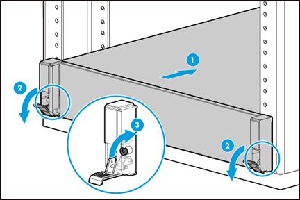
2. Secure the server as shown in Figure 3.
a. Push the server until the multifunctional rack mount ears are flush against the rack front posts, as shown by callout 1.
b. Unlock the latches of the multifunctional rack mount ears, as shown by callout 2.
c. Fasten the captive screws inside the chassis ears and lock the latches, as shown by callout 3.
Installing cable management brackets
Install cable management brackets if the server is shipped with cable management brackets. For information about how to install cable management brackets, see the installation guide shipped with the brackets.
Connecting external cables
Cabling guidelines
|
|
WARNING! To avoid electric shock, fire, or damage to the equipment, do not connect communication equipment to RJ-45 Ethernet ports on the server. |
· For heat dissipation, make sure no cables block the inlet or outlet air vents of the fan modules, heatsinks, GPUs, and PSUs.
· To easily identify ports and connect/disconnect cables, make sure the cables do not cross.
· Label the cables for easy identification of the cables.
· Wrap unused cables onto an appropriate position on the rack.
· To avoid damage to cables when extending the server out of the rack, do not route the cables too tight if you use cable management brackets.
Connecting a mouse, keyboard, and monitor
About this task
Perform this task before you configure HDM or enter the operating system of the server.
The server provides one DB15 VGA connector for connecting a monitor. The server is not shipped with a standard PS2 mouse and keyboard. To connect a PS2 mouse and keyboard, you must prepare a USB-to-PS2 adapter.
Procedure
1. Connect one plug of a VGA cable to a VGA connector on the server, and fasten the screws on the plug.
Figure 4 Connecting a VGA cable
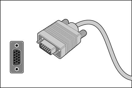
2. Connect the other plug of the VGA cable to the VGA connector on the monitor, and fasten the screws on the plug.
3. Connect the mouse and keyboard.
¡ For a USB mouse and keyboard, directly connect the USB connectors of the mouse and keyboard to the USB connectors on the server.
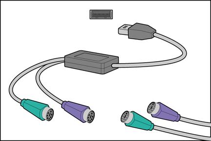
¡ For a PS2 mouse and keyboard, insert the USB connector of the USB-to-PS2 adapter to a USB connector on the server. Then, insert the PS2 connectors of the mouse and keyboard into the PS2 receptacles of the adapter.
Figure 5 Connecting a PS2 mouse and keyboard by using a USB-to-PS2 adapter
Connecting an Ethernet cable
About this task
Perform this task before you set up a network environment or log in to the HDM management interface through the HDM network port to manage the server.
Procedure
1. Determine the network port on the server.
¡ To connect the server to the external network, use one of the four Ethernet ports on the rear panel.
¡ To log in to the HDM management interface, use the HDM dedicated network port or the HDM shared network port (Ethernet interface 1) on the rear panel. For the location of the network ports, see "Rear panel."
2. Determine type of the Ethernet cable.
Verify the connectivity of the cable by using a link tester.
If you are replacing the Ethernet cable, make sure the new cable is the same type or compatible with the old cable.
3. Label the Ethernet cable by filling in the names and numbers of the server and the peer device on the label.
As a best practice, use labels of the same kind for all cables.
If you are replacing the Ethernet cable, label the new cable with the same number as the number of the old cable.
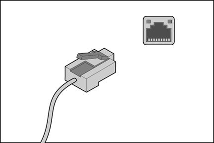
4. Connect one end of the Ethernet cable to the network port on the server and the other end to the peer device.
Figure 6 Connecting an Ethernet cable
5. Verify network connectivity.
After powering on the server, use the ping command to test the network connectivity. If the connection between the server and the peer device fails, verify that the Ethernet cable is securely connected.
6. Secure the Ethernet cable. For information about how to secure cables, see "Securing cables."
Connecting a USB device
About this task
Perform this task before you install the operating system of the server or transmit data through a USB device.
The server provides a maximum of five USB connectors.
· Three USB connectors on the front and rear panels.
· Two internal USB connectors for connecting USB devices that are not designed to be installed and removed very often.
Guidelines
Before connecting a USB device, make sure the USB device can operate correctly and then copy data to the USB device.
USB devices are hot swappable.
As a best practice for compatibility, purchase H3C-certified USB devices.
Procedure
1. (Optional.) Remove the access panel if you need to connect the USB device to an internal USB connector. For information about how to remove the access panel, see "Removing the access panel."
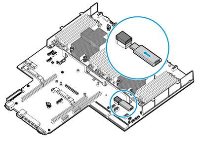
2. Connect the USB device to the USB connector, as shown in Figure 7.
Figure 7 Connecting a USB device to an internal USB connector
3. (Optional.) Install the access panel. For information about how to install the access panel, see "Installing the access panel."
4. Verify that the server can identify the USB device.
If the server fails to identify the USB device, download and install the driver of the USB device. If the server still fails to identify the USB device after the driver is installed, replace the USB device.
Connecting the power cord
Guidelines
|
|
WARNING! To avoid damage to the equipment or even bodily injury, use the power cord that ships with the server. |
Before connecting the power cord, make sure the server and components are installed correctly.
Procedure
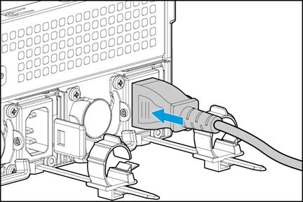
1. Insert the power cord plug into the power receptacle of a power supply at the rear panel, as shown in Figure 8.
Figure 8 Connecting the power cord
2. Connect the other end of the power cord to the power source, for example, the power strip on the rack.
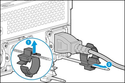
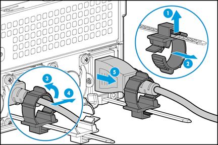
3. Secure the power cord to avoid unexpected disconnection of the power cord.
a. If the cable clamp is positioned too near the power cord that it blocks the power cord plug connection, press down the tab on the cable mount and slide the clip backward.
Figure 9 Sliding the cable clamp backward
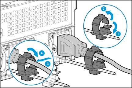
b. Open the cable clamp, place the power cord through the opening in the cable clamp, and then close the cable clamp, as shown by callouts 1, 2, 3, and 4 in Figure 10.
Figure 10 Securing the AC power cord
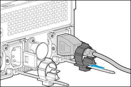
c. Slide the cable clamp forward until it is flush against the edge of the power cord plug, as shown in Figure 11.
Figure 11 Sliding the cable clamp forward
Securing cables
Securing cables to cable management brackets
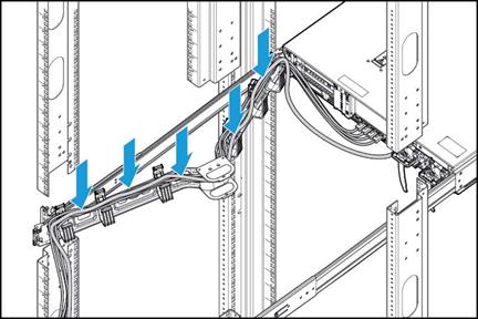
As shown in Figure 12, secure cables to cable management brackets.
Figure 12 Securing cables to cable management brackets
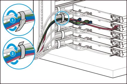
Securing cables to slide rails by using cable straps
You can secure cables to either left slide rails or right slide rails. As a best practice for cable management, secure cables to left slide rails.
When multiple cable straps are used in the same rack, stagger the strap location, so that the straps are adjacent to each other when viewed from top to bottom. This positioning will enable the slide rails to slide easily in and out of the rack.
To secure cables to slide rails by using cable straps:
1. Hold the cables against a slide rail.
2. Wrap the strap around the slide rail and loop the end of the cable strap through the buckle.
3. Dress the cable strap to ensure that the extra length and buckle part of the strap are facing outside of the slide rail.
Figure 13 Securing cables to a slide rail
Removing the server from a rack
1. Power down the server. For more information, see "Powering off the server."
2. Disconnect all peripheral cables from the server.
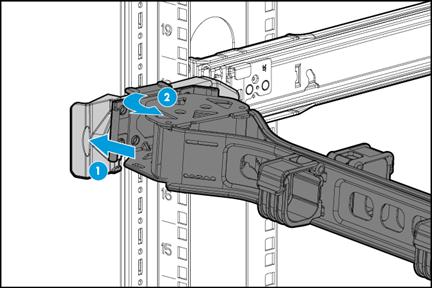
3. Open the cable management bracket, if any.
a. Press the tab as shown by callout 1 and pull the cable management bracket as shown in by callout 2.
Figure 14 Releasing the cable management bracket
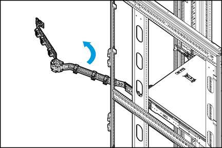
b. Open the cable management bracket.
Figure 15 Opening the cable management bracket
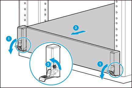
4. Extend the server from the rack.
a. Open the latches of the chassis ears.
b. Loosen the captive screws.
c. Slide the server out of the rack.
Figure 16 Extending the server from the rack
5. Place the server on a clean, stable surface.
Installing hardware options
If you are installing multiple hardware options, read their installation procedures and identify similar steps to streamline the entire installation procedure.
Installing drives
Guidelines
The drives are hot swappable.
Procedure
1. Remove the security bezel, if any. For more information, see "Removing the security bezel."
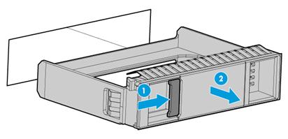
2. Press the latch on the drive blank inward with one hand, and pull the drive blank out of the slot.
Figure 17 Removing the drive blank
3. Install the drive:
Press the button on the drive panel to release the locking lever.
Figure 18 Releasing the locking lever
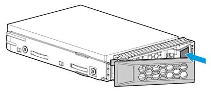
b. Insert the drive into the slot and push it gently until you cannot push it further.
Close the locking lever until it snaps into place.
4. (Optional.) Install the removed security bezel. For more information, see "Installing the security bezel."
Verifying the installation
Use the following methods to verify that the drive is installed correctly:
· Access the operating system of the server and verify the drive properties (including capacity).
· Observe the drive LEDs to verify that the drive is operating correctly. For more information, see drive LEDs in "Appendix B Component specifications."
Installing power supplies
Guidelines
· The power supplies are hot swappable.
· Make sure the installed power supplies are the same model. HDM will perform power supply consistency check and generate an alarm if the power supply models are different.
·
Procedure
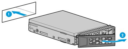
1. Remove the power supply blank from the target power supply slot.
Figure 20 Removing the power supply blank
2. Push the power supply into the slot until it snaps into place.
Figure 21 Installing a power supply
3. Connect the power cord. For more information, see "Connecting the power cord."
Verifying the installation
Use one of the following methods to verify that the power supply is installed correctly:
· Observe the power supply LED to verify that the power supply is operating correctly. For more information about the power supply LED, see LEDs in "Rear panel."
· Log in to HDM to verify that the power supply is operating correctly.
Installing a PCIe network adapter
Procedure
1. Power off the server. For more information, see "Powering off the server."
2. Remove the server from the rack. For more information, see "Removing the server from a rack."
3. Remove the access panel. For more information, see "Removing the access panel."
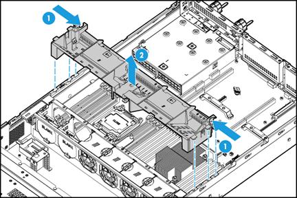
4. Remove the riser card. Lift the riser card out of the chassis.
Figure 22 Removing the riser card
5. Install the PCIe network adapter to the riser card:
a. Remove the PCIe module blank. Remove the screw that secures the blank and then pull the blank out of the slot.
Figure 23 Removing a PCIe module blank
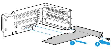
b. Slide the PCIe network adapter into the PCIe slot on the riser card, and use the screw to secure the network adapter.
Figure 24 Installing a PCIe network adapter to the riser card
6. Install the riser card to the server. Insert the riser card onto the PCIe riser connector along the guide rails.
Figure 25 Installing the riser card to the server

7. Install the access panel. For more information, see "Installing the access panel."
8. Rack-mount the server. For more information, see "Rack-mounting the server."
9. Connect the power cord. For more information, see "Connecting the power cord."
10. Power on the server. For more information, see "Powering on the server."
Verifying the installation
Log in to HDM to verify that the PCIe network adapter is operating correctly.
Installing DIMMs
About DIMMs
The server supports DDR4 DIMMs, which include LRDIMM and RDIMM.
· RDIMMs can perform parity check on addresses.
· Compared with RDIMMs, LRDIMMs provide larger capacity and higher bandwidth.
Guidelines
|
|
WARNING! The DIMMs are not hot swappable. |
You can install a maximum of 12 DIMMs for each processor, three DIMMs per DIMM channel. For more information, see DIMM slots in "Appendix A Server specifications."
When you install DIMMs, follow these restrictions and guidelines:
· Make sure the corresponding processor is present before powering on the server.
· Make sure all DIMMs installed on the server have the same specifications.
· Populate the white slots, then the black slots, and finally the blue slots. For example, for processor 1, populate DIMM slots A1 through A4 prior to DIMM slots A5 through A8, and populate DIMM slots A5 through A8 prior to DIMM slots A9 through A12.
· Populate DIMM channels in sequence. If only one processor is installed, start with the lowest numbered channel, for example, A1, A2, A3, and so on. If two processors are installed, start with the lowest numbered DIMM channels on the two memory controllers in alphabetic order, for example, A1, B1, A2, B2, A3, B3, and so on.
· For the memory mode setting to take effect, make sure the following DIMM installation requirements are met when you install DIMMs for a processor:
|
Memory mode |
DIMM requirements |
|
Mirror Lockstep |
Populate channel 1 and channel 2 in the same way, and populate channel 3 and channel 4 in the same way (same DIMM quantity, same slots, and same DIMM model). |
|
Memory Rank Sparing |
A minimum of 2 ranks per channel. |
|
|
NOTE: If the DIMM configuration does not meet the requirements for the configured memory mode, the system uses the default memory mode (Independent mode). For more information about configuring the memory mode, see "Appendix C Common software operations." |
Procedure
1. Power off the server. For more information, see "Powering off the server."
2. Remove the server from the rack. For more information, see "Removing the server from a rack."
3. Remove the access panel. For more information, see "Removing the access panel."
4. Remove the chassis air baffle. For more information, see "Removing the chassis air baffle."
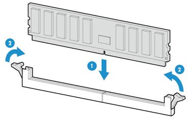
5. Install a DIMM:
a. Open the DIMM slot latches.
b. Align the notch on the DIMM with the connector key in the DIMM slot and press the DIMM into the socket until the latches lock the DIMM in place, as shown in Figure 26.
To avoid damage to the DIMM, do not use force to press the DIMM into the socket when you encounter resistance. Instead, re-align the notch with the connector key, and then reinsert the DIMM again.
6. Install the chassis air baffle. For more information, see "Installing the chassis air baffle."
7. Install the access panel. For more information, see "Installing the access panel."
8. Rack-mount the server. For more information, see "Rack-mounting the server."
9. Connect the power cord. For more information, see "Connecting the power cord."
10. Power on the server. For more information, see "Powering on the server."
Verifying the installation
Use one of the following methods to verify that the memory size is correct:
· Access the GUI or CLI of the server:
¡ In the GUI of a windows OS, click the Start icon in the bottom left corner, enter msinfo32 in the search box, and then click the msinfo32 item.
¡ In the CLI of a Linux OS, execute the cat /proc/meminfo command.
· Log in to HDM. For more information, see HDM online help.
· Access the BIOS and access the IntelRCSetup > Memory Configuration > Memory Configuration screen.
If the memory size is incorrect, re-install or replace the DIMM.
|
|
NOTE: It is normal that the CLI or GUI of the server OS displays a smaller memory size than the actual size if the mirror, partial mirror, or memory rank sparing memory mode is enabled. In this situation, you can verify the memory size from HDM or BIOS. |
Powering on and powering off the server
Important information
If the server is connected to external storage devices, make sure the server is the first device to power off and then the last device to power on. This restriction prevents the server from mistakenly identifying the external storage devices as faulty devices.
Powering on the server
Prerequisites
Before you power on the server, you must complete the following tasks:
· Install the server and internal components correctly.
· Connect the server to a power source.
Procedure
Powering on the server by pressing the power on/standby button
Press the power on/standby button to power on the server.
The server exits standby mode and supplies power to the system. The system power LED changes from steady amber to flashing green and then to steady green. For information about the position of the system power LED, see LEDs and buttons in "Appendix A Server specifications."
Powering on the server from the HDM Web interface
1. Log in to HDM.
For information about how to log in to HDM, see "Appendix C Common software operations."
2. Power on the server.
a. Select Power Management > Power Configuration.
b. Select Power on and then click Execute.
Powering on the server from the remote console interface
1. Log in to HDM.
For information about how to log in to HDM, see " Appendix C Common software operations."
2. Log in to a remote console.
3.
Click Power >
Power On Server or click the ![]() icon.
icon.
Configuring automatic power-on
Automatic power-on allows the server to start up automatically once a power cord is connected.
To configure automatic power-on:
1. Log in to HDM.
For information about how to log in to HDM, see " Appendix C Common software operations."
2. Configure automatic power-on for the server.
a. Select Power Management > Power Configuration.
b. Click the Automatic power-on tab and then select Always power on.
c. Click Save.
Powering off the server
Guidelines
Before powering off the server, you must complete the following tasks:
· Back up all critical data.
· Make sure all services have stopped or have been migrated to other servers.
Procedure
Powering off the server from its operating system
1. Connect a monitor, mouse, and keyboard to the server.
2. Shut down the operating system of the server.
3. Disconnect all power cords from the server.
Powering off the server by pressing the power on/standby button
|
|
IMPORTANT: This method forces the server to enter standby mode without properly exiting applications and the operating system. Use this method only when the server system crashes. For example, a process gets stuck. |
1. Press and hold the power on/standby button until the system power LED turns into steady amber.
2. Disconnect all power cords from the server.
Powering off the server from the HDM Web interface
1. Log in to HDM.
For information about how to log in to HDM, see " Appendix C Common software operations."
2. Select Power Management > Power Configuration.
3. Select Force power-off or Graceful power-off and then click Execute.
4. Disconnect all power cords from the server.
Powering off the server from the remote console interface
1. Log in to HDM.
For information about how to log in to HDM, see " Appendix C Common software operations."
2. Log in to a remote console.
3.
Click Power >
Force Power Off/Graceful Power Off, or click the ![]() icon.
icon.
4. Disconnect all power cords from the server.
Replacing hardware options
If you are replacing multiple hardware options, read their replacement procedures and identify similar steps to streamline the entire replacement procedure.
Replacing the security bezel
Removing the security bezel
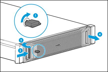
1. Insert the key provided with the bezel into the lock on the bezel. Hold down and turn the key 90 degree clockwise to unlock the security bezel, as shown by callout 1 in Figure 27.
|
|
CAUTION: To avoid damage to the lock, hold down the key while you are turning the key. |
2. Press the latch at the left end of the bezel, open the security bezel, and then release the latch, as shown by callouts 2 and 3 in Figure 27.
3. Pull the right edge of the security bezel out of the groove in the right chassis ear to remove the security bezel, as shown by callout 4 in Figure 27.
Figure 27 Removing the security bezel
Installing the security bezel
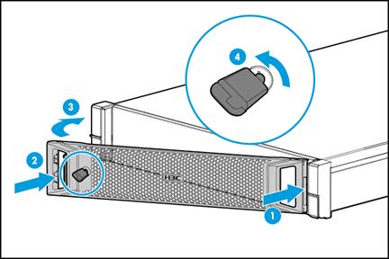
1. Press the right edge of the security bezel into the groove in the right chassis ear on the server, as shown by callout 1 in Figure 28.
2. Press the latch at the other end, close the security bezel, and then release the latch to secure the security bezel into place. See callouts 2 and 3 in Figure 28.
3. Insert the key provided with the bezel into the lock on the bezel and lock the security bezel, as shown by callout 4 in Figure 28. Then, pull out the key and keep it safe.
|
|
CAUTION: To avoid damage to the lock, hold down the key while you are turning the key. |
Figure 28 Installing the security bezel
Replacing a drive
Guidelines
The drives are hot swappable.
If you are using the drives to create a RAID, follow these restrictions and guidelines:
· To avoid degraded RAID performance or RAID creation failures, make sure all drives in the RAID are the same type (HDDs or SSDs) and have the same connector type (SAS or SATA).
· For efficient use of storage, use drives that have the same capacity to build a RAID. If the drives have different capacities, the lowest capacity is used across all drives in the RAID.
· Back up drive data before replacement.
· If the installed drive contains RAID information, you must clear the information before configuring RAIDs. As a best practice, install drives that do not contain RAID information.
Prerequisites
Identify the position of the drive to be replaced.
Identify the RAID array information of the drive to be replaced.
Procedure
1. Remove the security bezel, if any. For more information, see "Removing the security bezel."
2. Observe the drive LEDs to verify that the drive can be removed. For more information about drive LEDs, see drive LEDs in "Appendix B Component specifications."
3. Remove the drive. Press the button on the drive to release the locking lever, and then hold the locking lever and pull the drive out of the slot.

4. Install a new drive. For more information, see "Installing drives."
5. Install the removed security bezel, if any. For more information, see "Installing the security bezel."
Verifying the replacement
Use one of the following methods to verify that the drive has been replaced correctly:
· Verify the drive properties (including capacity) by using one of the following methods:
¡ Log in to HDM.
¡ Access the CLI or GUI of the server.
· Observe the drive LEDs to verify that the drive is operating correctly. For more information about drive LEDs, see drive LEDs in "Appendix B Component specifications."
Replacing the access panel
|
WARNING! To avoid bodily injury from hot surfaces, allow the server and its internal modules to cool before touching them. |
Removing the access panel
1. Power off the server. For more information, see "Powering off the server."
2. Remove the server from the rack. For more information, see "Removing the server from a rack."
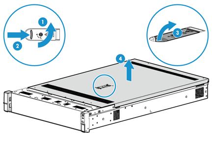
3. Remove the access panel, as shown in Figure 30.
a. If the locking lever on the access panel is locked, unlock the locking lever. Use a T15 Torx screwdriver to turn the screw on the lever, as shown by callout 1.
b. Press the latch on the locking lever, pull the locking lever upward, and then release the latch, as shown by callouts 2 and 3. The access panel will automatically slide to the rear of the server chassis.
c. Lift the access panel to remove it, as shown by callout 4.
Figure 30 Removing the access panel
Installing the access panel
1. Open the locking level on the access panel, as shown in Figure 31.
Figure 31 Opening the locking lever
2. Install the access panel as shown in Figure 32:
a. Place the access panel on top of the server chassis, with the guide pin in the chassis aligned with the pin hole in the locking lever area, as shown by callout 1.
b. Close the locking lever, as shown by callout 2. The access panel will automatically slide toward the server front to secure itself into place.
c. (Optional.) Lock the locking lever. Use a T15 Torx screwdriver to turn the screw on the lever, as shown by callout 3.
Figure 32 Installing the access panel
3. Mount the server in a rack. For more information, see "Rack-mounting the server."
4. Connect the power cord. For more information, see "Connecting the power cord."
5. Power on the server. For more information, see "Powering on the server."
Replacing a power supply
The power supplies are hot swappable.
If two power supplies are installed and sufficient space is available for replacement, you can replace a power supply without powering off or removing the server from the rack.
Procedure
1. Power off the server. For more information, see "Powering off the server."
2. Remove the server from the rack. For more information, see "Removing the server from a rack."
3. Disconnect the power cord from the power supply, as shown in Figure 33:
a. Press the tab to disengage the ratchet from the tie mount, slide the cable clamp outward, and then release the tab, as shown by callouts 1 and 2.
b. Open the cable clamp and remove the power cord out of the clamp, as shown by callouts 3 and 4.
c. Unplug the power cord, as shown by callout 5.
Figure 33 Removing the power cord
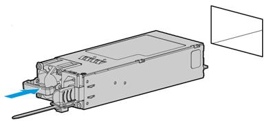
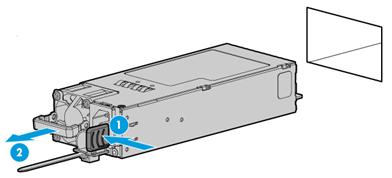
4. Holding the power supply by its handle and pressing the retaining latch with your thumb, pull the power supply slowly out of the slot, as shown in Figure 34:
Figure 34 Removing the power supply
5. Install a new power supply. For more information, see "Installing power supplies."
|
|
IMPORTANT: If the server is configured with only one power supply, you must install the power supply in slot 2. |
6. Mount the server in the rack. For more information, see "Rack-mounting the server."
7. Connect the power cord. For more information, see "Connecting the power cord."
8. Power on the server. For more information, see "Powering on the server."
Verifying the replacement
Use the following methods to verify that the power supply has been replaced correctly:
· Observe the power supply LED to verify that the power supply LED is steady or flashing green. For more information about the power supply LED, see LEDs in "Rear panel."
· Log in to HDM to verify that the power supply status is correct.
Replacing the chassis air baffle
|
WARNING! To avoid bodily injury from hot surfaces, allow the server and its internal modules to cool before touching them. |
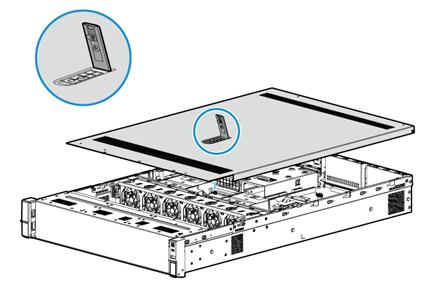
Removing the chassis air baffle
1. Power off the server. For more information, see "Powering off the server."
2. Remove the server from the rack. For more information, see "Removing the server from a rack."
3. Remove the access panel. For more information, see "Removing the access panel."
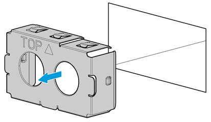
4. Remove the chassis air baffle. Hold the air baffle by the blue notches at both ends, and lift the air baffle out of the chassis, as shown in Figure 35.
Figure 35 Removing the chassis air baffle
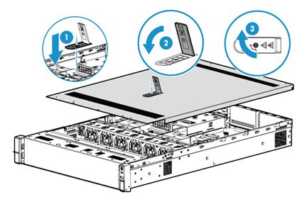
Installing the chassis air baffle
1. Install the chassis air baffle. Place the air baffle on top of the chassis, with the standouts at both ends of the air baffle aligned with the notches on the chassis edges, as shown in Figure 36.
Figure 36 Installing the chassis air baffle

2. Install the access panel. For more information, see "Installing the access panel."
3. Mount the server in a rack. For more information, see "Rack-mounting the server."
4. Connect the power cord. For more information, see "Connecting the power cord."
5. Power on the server. For more information, see "Powering on the server."
Replacing a PCIe network adapter
Procedure
1. Power off the server. For more information, see "Powering off the server."
2. Remove the server from the rack. For more information, see "Removing the server from a rack."
3. Remove the access panel. For more information, see "Removing the access panel."
4. Disconnect cables from the PCIe network adapter.
5. Remove the PCIe network adapter:
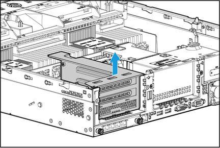
a. Remove the riser card. Lift the riser card out of the chassis.
Figure 37 Removing the riser card

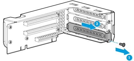
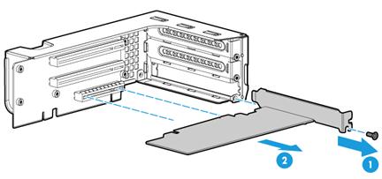
b. Remove the PCIe network adapter from the riser card. Remove the screw that secures the PCIe network adapter, and then pull the PCIe network adapter out of the slot.
Figure 38 Removing the PCIe network adapter from the riser card
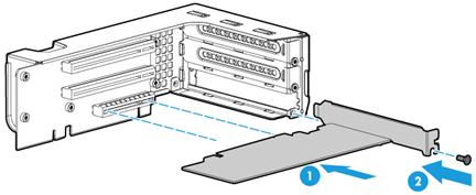
6. Install a new PCIe network adapter to the riser card. Insert the network adapter into the slot along the guide rails, and use a screw to secure it into place.
Figure 39 Installing a PCIe network adapter to the riser card.
7. Install the riser card to the server. Insert the riser card onto the PCIe riser connector along the guide rails.
Figure 40 Installing the riser card to the server

8. Connect cables to the PCIe network adapter.
9. Install the access panel. For more information, see "Installing the access panel."
10. Rack-mount the server. For more information, see "Rack-mounting the server."
11. Connect the power cord. For more information, see "Connecting the power cord."
12. Power on the server. For more information, see "Powering on the server."
Verifying the replacement
Log in to HDM to verify that the PCIe network adapter is in a correct state.
Replacing a fan
|
WARNING! To avoid bodily injury from hot surfaces, allow the server and its internal modules to cool before touching them. |
Removing a fan
The fans are hot swappable. If sufficient space is available for replacement, you can replace a fan without powering off the server or removing the server from the rack. The following procedure is provided based on the assumption that no sufficient space is available for replacement.
To remove a fan:
1. Power off the server. For more information, see "Powering off the server."
2. Remove the server from the rack. For more information, see "Removing the server from a rack."
3. Remove the access panel. For more information, see "Removing the access panel."
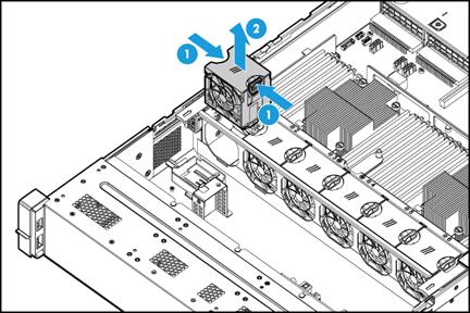
4. Remove a fan. Pin the latches at both sides of the fan and pull the fan out of the slot.
Installing a fan
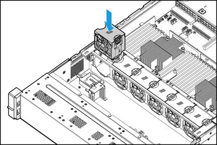
1. Insert a fan into the slot and push it until it snaps into place, as shown in Figure 42.
2. Install the access panel. For more information, see "Installing the access panel."
3. Rack-mount the server. For more information, see "Rack-mounting the server."
4. Connect the power cord. For more information, see "Connecting the power cord."
5. Power on the server. For more information, see "Powering on the server."
Verifying the installation
Log in to HDM to verify that the fan is operating correctly.
Replacing a DIMM
|
|
WARNING! To avoid bodily injury from hot surfaces, allow the server and its internal modules to cool before touching them. |
Guidelines
Make sure all the DIMMs installed on a server are the same model.
Procedure
1. Power off the server. For more information, see "Powering off the server."
2. Remove the server from the rack. For more information, see "Removing the server from a rack."
3. Remove the access panel. For more information, see "Removing the access panel."
4. Remove the chassis air baffle. For more information, see "Removing the chassis air baffle."
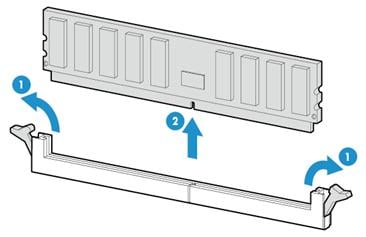
5. Remove a DIMM. Open the DIMM slot latches and pull the DIMM out of the slot.
6. Install a new DIMM. For more information, see "Installing DIMMs."
7. Install the chassis air baffle. For more information, see "Installing the chassis air baffle."
8. Install the access panel. For more information, see "Installing the access panel."
9. Rack-mount the server. For more information, see "Rack-mounting the server."
10. Connect the power cord. For more information, see "Connecting the power cord."
11. Power on the server. For more information, see "Powering on the server."
During server startup, you can access the BIOS to configure the DIMM memory mode. For more information, see " Appendix C Common software operations."
Verifying the replacement
Use one of the following methods to verify that the memory size is correct:
· Access the GUI or CLI of the server:
¡ In the GUI of a windows OS, click the Start icon in the bottom left corner, enter msinfo32 in the search box, and then click the msinfo32 item.
¡ In the CLI of a Linux OS, execute the cat /proc/meminfo command.
· Log in to HDM.
· Access BIOS and access the IntelRCSetup > Memory Configuration > Memory Configuration screen.
If the memory size is incorrect, re-install or replace the DIMM.
|
|
NOTE: It is normal that the CLI or GUI of the server OS displays a smaller memory size than the actual size if the mirror, partial mirror, or memory rank sparing memory mode is enabled. In this situation, you can verify the memory size from HDM or BIOS. |
Replacing the system battery
|
WARNING! To avoid bodily injury from hot surfaces, allow the server and its internal modules to cool before touching them. |
The server comes with a system battery installed on the system board, which supplies power to the real-time clock and has a lifespan of 5 to 10 years. If the server no longer automatically displays the correct date and time, you might need to replace the battery.
|
|
NOTE: The BIOS will restore to the default settings after the replacement. You must reconfigure the BIOS to have the desired settings, including the system date and time. |
Removing the system battery
1. Power off the server. For more information, see "Powering off the server."
2. Remove the server from the rack. For more information, see "Removing the server from a rack."
3. Remove the access panel. For more information, see "Removing the access panel."
4. Remove PCIe modules that might hinder system battery removal.
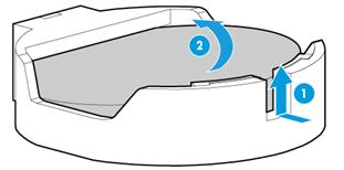
5. Remove the system battery, as shown in Figure 44.
a. Use a flat-head insulated tool to slightly pry the system battery up from the notch as shown by callout 1.
|
|
WARNING! To avoid damaging the battery holder or system board, do not use excessive force when prying up the battery. |
b. Pinch the battery by its top edge and slowly lift it out of the battery holder, as shown by callout 2.
Figure 44 Removing the system battery
|
|
NOTE: For environment protection purposes, dispose of the used-up system battery at a designated site. |
Installing the system battery
1. Install the system battery, as shown in Figure 45.
a. Insert the system battery with the plus sign "+" facing up into the battery holder, as shown by callout 1.
b. Press down the battery to secure it into place, as shown by callout 2.
Figure 45 Installing the system battery

2. Install the removed PCIe modules.
3. Install the access panel. For more information, see "Installing the access panel."
4. Rack-mount the server. For more information, see "Rack-mounting the server."
5. Connect the power cord. For more information, see "Connecting the power cord."
6. Power on the server. For more information, see "Powering on the server."
7. Access the BIOS to reconfigure the system date and time.
Verifying the replacement
Verify that the system date and time is displayed correctly.
Technical support
Collecting fault information
Before contacting H3C Support, collect the following server information to facilitate troubleshooting:
· Log and sensor information:
¡ Event logs, HDM logs (audit logs and update logs), and SDS logs.
¡ Sensor information in HDM.
· Product serial number.
· Product model and name.
· Snapshots of error messages and descriptions.
· Hardware change history, including installation, replacement, insertion, and removal of hardware.
· Third-party software installed on the server.
· Operating system type and version.
Preparing tools
Prepare the following tools for troubleshooting:
· T25, T15, and T10 Torx screwdrivers.
· Flat-head screwdriver.
· Cage nut insertion/extraction tool.
· Diagonal pliers.
· Multimeter.
· Interface cable (network cable, for example).
· Monitor (PC for example).
· ESD wrist strap, antistatic gloves, and antistatic clothing.
