- Table of Contents
-
- 11-Network Management and Monitoring Configuration Guide
- 00-Preface
- 01-System maintenance and debugging configuration
- 02-NQA configuration
- 03-NTP configuration
- 04-PTP configuration
- 05-SNMP configuration
- 06-RMON configuration
- 07-Event MIB configuration
- 08-NETCONF configuration
- 09-Puppet configuration
- 10-Chef configuration
- 11-CWMP configuration
- 12-EAA configuration
- 13-Process monitoring and maintenance configuration
- 14-Sampler configuration
- 15-Mirroring configuration
- 16-NetStream configuration
- 17-IPv6 NetStream configuration
- 18-sFlow configuration
- 19-Information center configuration
- 20-GOLD configuration
- 21-Packet capture configuration
- 22-VCF fabric configuration
- 23-Ansible configuration
- 24-iNQA configuration
- 25-Packet trace configuration
- 26-NetAnalysis configuration
- Related Documents
-
| Title | Size | Download |
|---|---|---|
| 03-NTP configuration | 530.50 KB |
Restrictions and guidelines: NTP configuration
Configuring NTP association mode
Configuring NTP in client/server mode
Configuring NTP in symmetric active/passive mode
Configuring NTP in broadcast mode
Configuring NTP in multicast mode
Configuring the local clock as the reference source
Configuring access control rights
Configuring NTP authentication
Configuring NTP authentication in client/server mode
Configuring NTP authentication in symmetric active/passive mode
Configuring NTP authentication in broadcast mode
Configuring NTP authentication in multicast mode
Controlling NTP message sending and receiving
Specifying a source address for NTP messages
Disabling an interface from receiving NTP messages
Configuring the maximum number of dynamic associations
Setting a DSCP value for NTP packets
Specifying the NTP time-offset thresholds for log and trap outputs
Display and maintenance commands for NTP
Example: Configuring NTP client/server association mode
Example: Configuring IPv6 NTP client/server association mode
Example: Configuring NTP symmetric active/passive association mode
Example: Configuring IPv6 NTP symmetric active/passive association mode
Example: Configuring NTP broadcast association mode
Example: Configuring NTP multicast association mode
Example: Configuring IPv6 NTP multicast association mode
Example: Configuring NTP authentication in client/server association mode
Example: Configuring NTP authentication in broadcast association mode
Example: Configuring MPLS L3VPN network time synchronization in client/server mode
Example: Configuring MPLS L3VPN network time synchronization in symmetric active/passive mode
Restrictions and guidelines: SNTP configuration
Specifying an NTP server for the device
Configuring SNTP authentication
Specifying the SNTP time-offset thresholds for log and trap outputs
Configuring NTP
About NTP
NTP is used to synchronize system clocks among distributed time servers and clients on a network. NTP runs over UDP and uses UDP port 123.
NTP application scenarios
Various tasks, including network management, charging, auditing, and distributed computing depend on accurate and synchronized system time setting on the network devices. NTP is typically used in large networks to dynamically synchronize time among network devices.
NTP guarantees higher clock accuracy than manual system clock setting. In a small network that does not require high clock accuracy, you can keep time synchronized among devices by changing their system clocks one by one.
NTP working mechanism
Figure 1 shows how NTP synchronizes the system time between two devices (Device A and Device B, in this example). Assume that:
· Prior to the time synchronization, the time is set to 10:00:00 am for Device A and 11:00:00 am for Device B.
· Device B is used as the NTP server. Device A is to be synchronized to Device B.
· It takes 1 second for an NTP message to travel from Device A to Device B, and from Device B to Device A.
· It takes 1 second for Device B to process the NTP message.
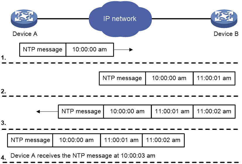
The synchronization process is as follows:
1. Device A sends Device B an NTP message, which is timestamped when it leaves Device A. The time stamp is 10:00:00 am (T1).
2. When this NTP message arrives at Device B, Device B adds a timestamp showing the time when the message arrived at Device B. The timestamp is 11:00:01 am (T2).
3. When the NTP message leaves Device B, Device B adds a timestamp showing the time when the message left Device B. The timestamp is 11:00:02 am (T3).
4. When Device A receives the NTP message, the local time of Device A is 10:00:03 am (T4).
Up to now, Device A can calculate the following parameters based on the timestamps:
· The roundtrip delay of the NTP message: Delay = (T4 – T1) – (T3 – T2) = 2 seconds.
· Time difference between Device A and Device B: Offset = [ (T2 – T1) + (T3 – T4) ] /2 = 1 hour.
Based on these parameters, Device A can be synchronized to Device B.
This is only a rough description of the work mechanism of NTP. For more information, see the related protocols and standards.
NTP architecture
NTP uses stratums 1 to 16 to define clock accuracy, as shown in Figure 2. A lower stratum value represents higher accuracy. Clocks at stratums 1 through 15 are in synchronized state, and clocks at stratum 16 are not synchronized.
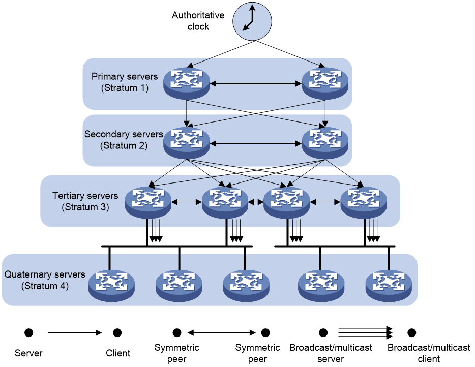
A stratum 1 NTP server gets its time from an authoritative time source, such as an atomic clock. It provides time for other devices as the primary NTP server. A stratum 2 time server receives its time from a stratum 1 time server, and so on.
To ensure time accuracy and availability, you can specify multiple NTP servers for a device. The device selects an optimal NTP server as the clock source based on parameters such as stratum. The clock that the device selects is called the reference source. For more information about clock selection, see the related protocols and standards.
If the devices in a network cannot synchronize to an authoritative time source, you can perform the following tasks:
· Select a device that has a relatively accurate clock from the network.
· Use the local clock of the device as the reference clock to synchronize other devices in the network.
NTP association modes
NTP supports the following association modes:
· Client/server mode
· Symmetric active/passive mode
· Broadcast mode
· Multicast mode
You can select one or more association modes for time synchronization. Table 1 provides detailed description for the four association modes.
In this document, an "NTP server" or a "server" refers to a device that operates as an NTP server in client/server mode. Time servers refer to all the devices that can provide time synchronization, including NTP servers, NTP symmetric peers, broadcast servers, and multicast servers.
|
Mode |
Working process |
Principle |
Application scenario |
|
Client/server |
On the client, specify the IP address of the NTP server. A client sends a clock synchronization message to the NTP servers. Upon receiving the message, the servers automatically operate in server mode and send a reply. If the client can be synchronized to multiple time servers, it selects an optimal clock and synchronizes its local clock to the optimal reference source after receiving the replies from the servers. |
A client can synchronize to a server, but a server cannot synchronize to a client. |
As Figure 2 shows, this mode is intended for configurations where devices of a higher stratum synchronize to devices with a lower stratum. |
|
Symmetric active/passive |
On the symmetric active peer, specify the IP address of the symmetric passive peer. A symmetric active peer periodically sends clock synchronization messages to a symmetric passive peer. The symmetric passive peer automatically operates in symmetric passive mode and sends a reply. If the symmetric active peer can be synchronized to multiple time servers, it selects an optimal clock and synchronizes its local clock to the optimal reference source after receiving the replies from the servers. |
A symmetric active peer and a symmetric passive peer can be synchronized to each other. If both of them are synchronized, the peer with a higher stratum is synchronized to the peer with a lower stratum. |
As Figure 2 shows, this mode is most often used between servers with the same stratum to operate as a backup for one another. If a server fails to communicate with all the servers of a lower stratum, the server can still synchronize to the servers of the same stratum. |
|
Broadcast |
A server periodically sends clock synchronization messages to the broadcast address 255.255.255.255. Clients listen to the broadcast messages from the servers to synchronize to the server according to the broadcast messages. When a client receives the first broadcast message, the client and the server start to exchange messages to calculate the network delay between them. Then, only the broadcast server sends clock synchronization messages. |
A broadcast client can synchronize to a broadcast server, but a broadcast server cannot synchronize to a broadcast client. |
A broadcast server sends clock synchronization messages to synchronize clients in the same subnet. As Figure 2 shows, broadcast mode is intended for configurations involving one or a few servers and a potentially large client population. The broadcast mode has lower time accuracy than the client/server and symmetric active/passive modes because only the broadcast servers send clock synchronization messages. |
|
Multicast |
A multicast server periodically sends clock synchronization messages to the user-configured multicast address. Clients listen to the multicast messages from servers and synchronize to the server according to the received messages. |
A multicast client can synchronize to a multicast server, but a multicast server cannot synchronize to a multicast client. |
A multicast server can provide time synchronization for clients in the same subnet or in different subnets. The multicast mode has lower time accuracy than the client/server and symmetric active/passive modes. |
.
NTP security
To improve time synchronization security, NTP provides the access control and authentication functions.
NTP access control
You can control NTP access by using an ACL. The access rights are in the following order, from the least restrictive to the most restrictive:
· Peer—Allows time requests and NTP control queries (such as alarms, authentication status, and time server information) and allows the local device to synchronize itself to a peer device.
· Server—Allows time requests and NTP control queries, but does not allow the local device to synchronize itself to a peer device.
· Synchronization—Allows only time requests from a system whose address passes the access list criteria.
· Query—Allows only NTP control queries from a peer device to the local device.
When the device receives an NTP request, it matches the request against the access rights in order from the least restrictive to the most restrictive: peer, server, synchronization, and query.
· If no NTP access control is configured, the peer access right applies.
· If the IP address of the peer device matches a permit statement in an ACL, the access right is granted to the peer device. If a deny statement or no ACL is matched, no access right is granted.
· If no ACL is specified for an access right or the ACL specified for the access right is not created, the access right is not granted.
· If none of the ACLs specified for the access rights is created, the peer access right applies.
· If none of the ACLs specified for the access rights contains rules, no access right is granted.
This feature provides minimal security for a system running NTP. A more secure method is NTP authentication.
NTP authentication
Use this feature to authenticate the NTP messages for security purposes. If an NTP message passes authentication, the device can receive it and get time synchronization information. If not, the device discards the message. This function makes sure the device does not synchronize to an unauthorized time server.
Figure 3 NTP authentication
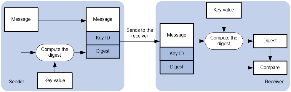
As shown in Figure 3, NTP authentication is performed as follows:
1. The sender uses the key identified by the key ID to calculate a digest for the NTP message through the MD5/HMAC authentication algorithm. Then it sends the calculated digest together with the NTP message and key ID to the receiver.
2. Upon receiving the message, the receiver performs the following actions:
a. Finds the key according to the key ID in the message.
b. Uses the key and the MD5/HMAC authentication algorithm to calculate the digest for the message.
c. Compares the digest with the digest contained in the NTP message.
- If they are different, the receiver discards the message.
- If they are the same and an NTP association is not required to be established, the receiver provides a response packet. For information about NTP associations, see "Configuring the maximum number of dynamic associations."
- If they are the same and an NTP association is required to be established or has existed, the local device determines whether the sender is allowed to use the authentication ID. If the sender is allowed to use the authentication ID, the receiver accepts the message. If the sender is not allowed to use the authentication ID, the receiver discards the message.
NTP for MPLS L3VPN instances
On an MPLS L3VPN network, a PE that acts as an NTP client or active peer can synchronize with the NTP server or passive peer in an MPLS L3VPN instance.
As shown in Figure 4, users in VPN 1 and VPN 2 are connected to the MPLS backbone network through provider edge (PE) devices. VPN instances vpn1 and vpn2 have been created for VPN 1 and VPN 2, respectively on the PEs. Services of the two VPN instances are isolated. Time synchronization between PEs and devices in the two VPN instances can be realized if you perform the following tasks:
· Configure the PEs to operate in NTP client or symmetric active mode.
· Specify the VPN instance to which the NTP server or NTP symmetric passive peer belongs.
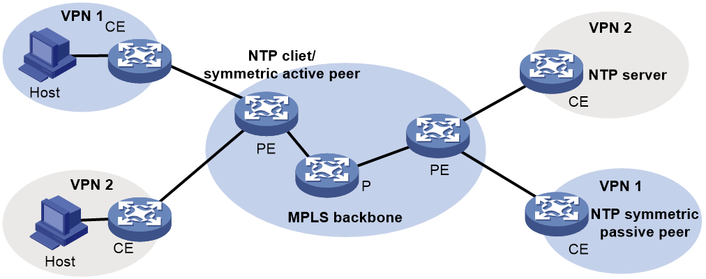
For more information about MPLS L3VPN, VPN instance, and PE, see MPLS Configuration Guide.
Protocols and standards
· RFC 1305, Network Time Protocol (Version 3) Specification, Implementation and Analysis
· RFC 5905, Network Time Protocol Version 4: Protocol and Algorithms Specification
Restrictions and guidelines: NTP configuration
· You cannot configure both NTP and SNTP on the same device.
· NTP is supported only on the following Layer 3 interfaces:
¡ Layer 3 Ethernet interfaces.
¡ Layer 3 Ethernet subinterfaces.
¡ Layer 3 aggregate interfaces.
¡ Layer 3 aggregate subinterfaces.
¡ VLAN interfaces.
¡ Tunnel interfaces.
· Do not configure NTP settings on an aggregate member port.
· The NTP service and SNTP service are mutually exclusive. You can only enable either NTP service or SNTP service at a time.
· To avoid frequent time changes or even synchronization failures, do not specify more than one reference source on a network.
· For correct time synchronization, make sure the time offset between the system time and the NTP clock source is less than 68 years.
· To use NTP for time synchronization, you must use the clock protocol command to specify NTP for obtaining the time. For more information about the clock protocol command, see device management commands in Fundamentals Command Reference.
NTP tasks at a glance
To configure NTP, perform the following tasks:
2. Configuring NTP association mode
¡ Configuring NTP in client/server mode
¡ Configuring NTP in symmetric active/passive mode
¡ Configuring NTP in broadcast mode
¡ Configuring NTP in multicast mode
3. (Optional.) Configuring the local clock as the reference source
4. (Optional.) Configuring access control rights
5. (Optional.) Configuring NTP authentication
¡ Configuring NTP authentication in client/server mode
¡ Configuring NTP authentication in symmetric active/passive mode
¡ Configuring NTP authentication in broadcast mode
¡ Configuring NTP authentication in multicast mode
6. (Optional.) Controlling NTP message sending and receiving
¡ Specifying a source address for NTP messages
¡ Disabling an interface from receiving NTP messages
¡ Configuring the maximum number of dynamic associations
¡ Setting a DSCP value for NTP packets
7. (Optional.) Specifying the NTP time-offset thresholds for log and trap outputs
Enabling the NTP service
Restrictions and guidelines
NTP and SNTP are mutually exclusive. Before you enable NTP, make sure SNTP is disabled.
Procedure
1. Enter system view.
system-view
2. Enable the NTP service.
ntp-service enable
By default, the NTP service is disabled.
Configuring NTP association mode
Configuring NTP in client/server mode
Restrictions and guidelines
To configure NTP in client/server mode, specify an NTP server for the client.
For a client to synchronize to an NTP server, make sure the server is synchronized by other devices or uses its local clock as the reference source.
If the stratum level of a server is higher than or equal to a client, the client will not synchronize to that server.
You can specify multiple servers for a client by executing the ntp-service unicast-server or ntp-service ipv6 unicast-server command multiple times.
Procedure
1. Enter system view.
system-view
2. Specify an NTP server for the device.
IPv4:
ntp-service unicast-server { server-name | ip-address } [ vpn-instance vpn-instance-name ] [ authentication-keyid keyid | maxpoll maxpoll-interval | minpoll minpoll-interval | priority | source interface-type interface-number | version number ] *
IPv6:
ntp-service ipv6 unicast-server { server-name | ipv6-address } [ vpn-instance vpn-instance-name ] [ authentication-keyid keyid | maxpoll maxpoll-interval | minpoll minpoll-interval | priority | source interface-type interface-number ] *
By default, no NTP server is specified.
Configuring NTP in symmetric active/passive mode
Restrictions and guidelines
To configure NTP in symmetric active/passive mode, specify a symmetric passive peer for the active peer.
For a symmetric passive peer to process NTP messages from a symmetric active peer, execute the ntp-service enable command on the symmetric passive peer to enable NTP.
For time synchronization between the symmetric active peer and the symmetric passive peer, make sure either or both of them are in synchronized state.
You can specify multiple symmetric passive peers by executing the ntp-service unicast-peer or ntp-service ipv6 unicast-peer command multiple times.
Procedure
1. Enter system view.
system-view
2. Specify a symmetric passive peer for the device.
IPv4:
ntp-service unicast-peer { peer-name | ip-address } [ vpn-instance vpn-instance-name ] [ authentication-keyid keyid | maxpoll maxpoll-interval | minpoll minpoll-interval | priority | source interface-type interface-number | version number ] *
IPv6:
ntp-service ipv6 unicast-peer { peer-name | ipv6-address } [ vpn-instance vpn-instance-name ] [ authentication-keyid keyid | maxpoll maxpoll-interval | minpoll minpoll-interval | priority | source interface-type interface-number ] *
By default, no symmetric passive peer is specified.
Configuring NTP in broadcast mode
Restrictions and guidelines
To configure NTP in broadcast mode, you must configure an NTP broadcast client and an NTP broadcast server.
For a broadcast client to synchronize to a broadcast server, make sure the broadcast server is synchronized by other devices or uses its local clock as the reference source.
Configuring the broadcast client
1. Enter system view.
system-view
2. Enter interface view.
interface interface-type interface-number
3. Configure the device to operate in broadcast client mode.
ntp-service broadcast-client
By default, the device does not operate in any NTP association mode.
After you execute the command, the device receives NTP broadcast messages from the specified interface.
Configuring the broadcast server
1. Enter system view.
system-view
2. Enter interface view.
interface interface-type interface-number
3. Configure the device to operate in NTP broadcast server mode.
ntp-service broadcast-server [ authentication-keyid keyid | version number ] *
By default, the device does not operate in any NTP association mode.
After you execute the command, the device sends NTP broadcast messages from the specified interface.
Configuring NTP in multicast mode
Restrictions and guidelines
To configure NTP in multicast mode, you must configure an NTP multicast client and an NTP multicast server.
For a multicast client to synchronize to a multicast server, make sure the multicast server is synchronized by other devices or uses its local clock as the reference source.
Configuring a multicast client
1. Enter system view.
system-view
2. Enter interface view.
interface interface-type interface-number
3. Configure the device to operate in multicast client mode.
IPv4:
ntp-service multicast-client [ ip-address ]
IPv6:
ntp-service ipv6 multicast-client ipv6-address
By default, the device does not operate in any NTP association mode.
After you execute the command, the device receives NTP multicast messages from the specified interface.
Configuring the multicast server
1. Enter system view.
system-view
2. Enter interface view.
interface interface-type interface-number
3. Configure the device to operate in multicast server mode.
IPv4:
ntp-service multicast-server [ ip-address ] [ authentication-keyid keyid | ttl ttl-number | version number ] *
IPv6:
ntp-service ipv6 multicast-server ipv6-address [ authentication-keyid keyid | ttl ttl-number ] *
By default, the device does not operate in any NTP association mode.
After you execute the command, the device sends NTP multicast messages from the specified interface.
Configuring the local clock as the reference source
About this task
This task enables the device to use the local clock as the reference so that the device is synchronized.
Restrictions and guidelines
Make sure the local clock can provide the time accuracy required for the network. After you configure the local clock as the reference source, the local clock is synchronized, and can operate as a time server to synchronize other devices in the network. If the local clock is incorrect, timing errors occur.
The system time reverts to the initial BIOS default after a cold reboot. As a best practice, do not configure the local clock as the reference source or configure the device as a time server.
Devices differ in clock precision. As a best practice to avoid network flapping and clock synchronization failure, configure only one reference clock on the same network segment and make sure the clock has high precision.
Prerequisites
Before you configure this feature, adjust the local system time to ensure that it is accurate.
Procedure
1. Enter system view.
system-view
2. Configure the local clock as the reference source.
ntp-service refclock-master [ ip-address ] [ stratum ]
By default, the device does not use the local clock as the reference source.
Configuring access control rights
Prerequisites
Before you configure the right for peer devices to access the NTP services on the local device, create and configure ACLs associated with the access right. For information about configuring an ACL, see ACL and QoS Configuration Guide.
Procedure
1. Enter system view.
system-view
2. Configure the right for peer devices to access the NTP services on the local device.
IPv4:
ntp-service access { peer | query | server | synchronization } acl ipv4-acl-number
IPv6:
ntp-service ipv6 { peer | query | server | synchronization } acl ipv6-acl-number
By default, the right for peer devices to access the NTP services on the local device is peer.
Configuring NTP authentication
Configuring NTP authentication in client/server mode
Restrictions and guidelines
To ensure a successful NTP authentication in client/server mode, configure the same authentication key ID, algorithm, and key on the server and client. Make sure the peer device is allowed to use the key ID for authentication on the local device.
NTP authentication results differ when different configurations are performed on client and server. For more information, see Table 2. (N/A in the table means that whether the configuration is performed or not does not make any difference.)
Table 2 NTP authentication results
|
Client |
Server |
||||
|
Enable NTP authentication |
Specify the server and key |
Trusted key |
Enable NTP authentication |
Trusted key |
|
|
Successful authentication |
|||||
|
Yes |
Yes |
Yes |
Yes |
Yes |
|
|
Failed authentication |
|||||
|
Yes |
Yes |
Yes |
Yes |
No |
|
|
Yes |
Yes |
Yes |
No |
N/A |
|
|
Yes |
Yes |
No |
N/A |
N/A |
|
|
Authentication not performed |
|||||
|
Yes |
No |
N/A |
N/A |
N/A |
|
|
No |
N/A |
N/A |
N/A |
N/A |
|
Configuring NTP authentication for a client
1. Enter system view.
system-view
2. Enable NTP authentication.
ntp-service authentication enable
By default, NTP authentication is disabled.
3. Configure an NTP authentication key.
ntp-service authentication-keyid keyid authentication-mode { hmac-sha-1 | hmac-sha-256 | hmac-sha-384 | hmac-sha-512 | md5 } { cipher | simple } string [ acl ipv4-acl-number | ipv6 acl ipv6-acl-number ] *
By default, no NTP authentication key exists.
4. Configure the key as a trusted key.
ntp-service reliable authentication-keyid keyid
By default, no authentication key is configured as a trusted key.
5. Associate the specified key with an NTP server.
IPv4:
ntp-service unicast-server { server-name | ip-address } [ vpn-instance vpn-instance-name ] authentication-keyid keyid
IPv6:
ntp-service ipv6 unicast-server { server-name | ipv6-address } [ vpn-instance vpn-instance-name ] authentication-keyid keyid
Configuring NTP authentication for a server
1. Enter system view.
system-view
2. Enable NTP authentication.
ntp-service authentication enable
By default, NTP authentication is disabled.
3. Configure an NTP authentication key.
ntp-service authentication-keyid keyid authentication-mode { hmac-sha-1 | hmac-sha-256 | hmac-sha-384 | hmac-sha-512 | md5 } { cipher | simple } string [ acl ipv4-acl-number | ipv6 acl ipv6-acl-number ] *
By default, no NTP authentication key exists.
4. Configure the key as a trusted key.
ntp-service reliable authentication-keyid keyid
By default, no authentication key is configured as a trusted key.
Configuring NTP authentication in symmetric active/passive mode
Restrictions and guidelines
To ensure a successful NTP authentication in symmetric active/passive mode, configure the same authentication key ID, algorithm, and key on the active peer and passive peer. Make sure the peer device is allowed to use the key ID for authentication on the local device.
NTP authentication results differ when different configurations are performed on active peer and passive peer. For more information, see Table 3. (N/A in the table means that whether the configuration is performed or not does not make any difference.)
Table 3 NTP authentication results
|
Active peer |
Passive peer |
||||
|
Enable NTP authentication |
Specify the peer and key |
Trusted key |
Stratum level |
Enable NTP authentication |
Trusted key |
|
Successful authentication |
|||||
|
Yes |
Yes |
Yes |
N/A |
Yes |
Yes |
|
Failed authentication |
|||||
|
Yes |
Yes |
Yes |
N/A |
Yes |
No |
|
Yes |
Yes |
Yes |
N/A |
No |
N/A |
|
Yes |
No |
N/A |
N/A |
Yes |
N/A |
|
No |
N/A |
N/A |
N/A |
Yes |
N/A |
|
Yes |
Yes |
No |
Larger than the passive peer |
N/A |
N/A |
|
Yes |
Yes |
No |
Smaller than the passive peer |
Yes |
N/A |
|
Authentication not performed |
|||||
|
Yes |
No |
N/A |
N/A |
No |
N/A |
|
No |
N/A |
N/A |
N/A |
No |
N/A |
|
Yes |
Yes |
No |
Smaller than the passive peer |
No |
N/A |
Configuring NTP authentication for an active peer
1. Enter system view.
system-view
2. Enable NTP authentication.
ntp-service authentication enable
By default, NTP authentication is disabled.
3. Configure an NTP authentication key.
ntp-service authentication-keyid keyid authentication-mode { hmac-sha-1 | hmac-sha-256 | hmac-sha-384 | hmac-sha-512 | md5 } { cipher | simple } string [ acl ipv4-acl-number | ipv6 acl ipv6-acl-number ] *
By default, no NTP authentication key exists.
4. Configure the key as a trusted key.
ntp-service reliable authentication-keyid keyid
By default, no authentication key is configured as a trusted key.
5. Associate the specified key with a passive peer.
IPv4:
ntp-service unicast-peer { ip-address | peer-name } [ vpn-instance vpn-instance-name ] authentication-keyid keyid
IPv6:
ntp-service ipv6 unicast-peer { ipv6-address | peer-name } [ vpn-instance vpn-instance-name ] authentication-keyid keyid
Configuring NTP authentication for a passive peer
1. Enter system view.
system-view
2. Enable NTP authentication.
ntp-service authentication enable
By default, NTP authentication is disabled.
3. Configure an NTP authentication key.
ntp-service authentication-keyid keyid authentication-mode { hmac-sha-1 | hmac-sha-256 | hmac-sha-384 | hmac-sha-512 | md5 } { cipher | simple } string [ acl ipv4-acl-number | ipv6 acl ipv6-acl-number ] *
By default, no NTP authentication key exists.
4. Configure the key as a trusted key.
ntp-service reliable authentication-keyid keyid
By default, no authentication key is configured as a trusted key.
Configuring NTP authentication in broadcast mode
Restrictions and guidelines
To ensure a successful NTP authentication in broadcast mode, configure the same authentication key ID, algorithm, and key on the broadcast server and client. Make sure the peer device is allowed to use the key ID for authentication on the local device.
NTP authentication results differ when different configurations are performed on broadcast client and server. For more information, see Table 4. (N/A in the table means that whether the configuration is performed or not does not make any difference.)
Table 4 NTP authentication results
|
Broadcast server |
Broadcast client |
|||
|
Enable NTP authentication |
Specify the server and key |
Trusted key |
Enable NTP authentication |
Trusted key |
|
Successful authentication |
||||
|
Yes |
Yes |
Yes |
Yes |
Yes |
|
Failed authentication |
||||
|
Yes |
Yes |
Yes |
Yes |
No |
|
Yes |
Yes |
Yes |
No |
N/A |
|
Yes |
Yes |
No |
Yes |
N/A |
|
Yes |
No |
N/A |
Yes |
N/A |
|
No |
N/A |
N/A |
Yes |
N/A |
|
Authentication not performed |
||||
|
Yes |
Yes |
No |
No |
N/A |
|
Yes |
No |
N/A |
No |
N/A |
|
No |
N/A |
N/A |
No |
N/A |
Configuring NTP authentication for a broadcast client
1. Enter system view.
system-view
2. Enable NTP authentication.
ntp-service authentication enable
By default, NTP authentication is disabled.
3. Configure an NTP authentication key.
ntp-service authentication-keyid keyid authentication-mode { hmac-sha-1 | hmac-sha-256 | hmac-sha-384 | hmac-sha-512 | md5 } { cipher | simple } string [ acl ipv4-acl-number | ipv6 acl ipv6-acl-number ] *
By default, no NTP authentication key exists.
4. Configure the key as a trusted key.
ntp-service reliable authentication-keyid keyid
By default, no authentication key is configured as a trusted key.
Configuring NTP authentication for a broadcast server
1. Enter system view.
system-view
2. Enable NTP authentication.
ntp-service authentication enable
By default, NTP authentication is disabled.
3. Configure an NTP authentication key.
ntp-service authentication-keyid keyid authentication-mode { hmac-sha-1 | hmac-sha-256 | hmac-sha-384 | hmac-sha-512 | md5 } { cipher | simple } string [ acl ipv4-acl-number | ipv6 acl ipv6-acl-number ] *
By default, no NTP authentication key exists.
4. Configure the key as a trusted key.
ntp-service reliable authentication-keyid keyid
By default, no authentication key is configured as a trusted key.
5. Enter interface view.
interface interface-type interface-number
6. Associate the specified key with the broadcast server.
ntp-service broadcast-server authentication-keyid keyid
By default, the broadcast server is not associated with a key.
Configuring NTP authentication in multicast mode
Restrictions and guidelines
To ensure a successful NTP authentication in multicast mode, configure the same authentication key ID, algorithm, and key on the multicast server and client. Make sure the peer device is allowed to use the key ID for authentication on the local device.
NTP authentication results differ when different configurations are performed on broadcast client and server. For more information, see Table 5. (N/A in the table means that whether the configuration is performed or not does not make any difference.)
Table 5 NTP authentication results
|
Multicast server |
Multicast client |
|||
|
Enable NTP authentication |
Specify the server and key |
Trusted key |
Enable NTP authentication |
Trusted key |
|
Successful authentication |
||||
|
Yes |
Yes |
Yes |
Yes |
Yes |
|
Failed authentication |
||||
|
Yes |
Yes |
Yes |
Yes |
No |
|
Yes |
Yes |
Yes |
No |
N/A |
|
Yes |
Yes |
No |
Yes |
N/A |
|
Yes |
No |
N/A |
Yes |
N/A |
|
No |
N/A |
N/A |
Yes |
N/A |
|
Authentication not performed |
||||
|
Yes |
Yes |
No |
No |
N/A |
|
Yes |
No |
N/A |
No |
N/A |
|
No |
N/A |
N/A |
No |
N/A |
Configuring NTP authentication for a multicast client
1. Enter system view.
system-view
2. Enable NTP authentication.
ntp-service authentication enable
By default, NTP authentication is disabled.
3. Configure an NTP authentication key.
ntp-service authentication-keyid keyid authentication-mode { hmac-sha-1 | hmac-sha-256 | hmac-sha-384 | hmac-sha-512 | md5 } { cipher | simple } string [ acl ipv4-acl-number | ipv6 acl ipv6-acl-number ] *
By default, no NTP authentication key exists.
4. Configure the key as a trusted key.
ntp-service reliable authentication-keyid keyid
By default, no authentication key is configured as a trusted key.
Configuring NTP authentication for a multicast server
1. Enter system view.
system-view
2. Enable NTP authentication.
ntp-service authentication enable
By default, NTP authentication is disabled.
3. Configure an NTP authentication key.
ntp-service authentication-keyid keyid authentication-mode { hmac-sha-1 | hmac-sha-256 | hmac-sha-384 | hmac-sha-512 | md5 } { cipher | simple } string [ acl ipv4-acl-number | ipv6 acl ipv6-acl-number ] *
By default, no NTP authentication key exists.
4. Configure the key as a trusted key.
ntp-service reliable authentication-keyid keyid
By default, no authentication key is configured as a trusted key.
5. Enter interface view.
interface interface-type interface-number
6. Associate the specified key with a multicast server.
IPv4:
ntp-service multicast-server [ ip-address ] authentication-keyid keyid
IPv6:
ntp-service ipv6 multicast-server ipv6-multicast-address authentication-keyid keyid
By default, no multicast server is associated with the specified key.
Controlling NTP message sending and receiving
Specifying a source address for NTP messages
About this task
You can specify a source address for NTP messages directly or by specifying a source interface. If you specify a source interface for NTP messages, the device uses the IP address of the specified interface as the source address to send NTP messages.
Restrictions and guidelines
To prevent interface status changes from causing NTP communication failures, specify an interface that is always up as the source interface, a loopback interface for example.
When the device responds to an NTP request, the source IP address of the NTP response is always the IP address of the interface that has received the NTP request.
If you have specified the source interface for NTP messages in the ntp-service unicast-server/ntp-service ipv6 unicast-server or ntp-service unicast-peer/ntp-service ipv6 unicast-peer command, the IP address of the specified interface is used as the source IP address for NTP messages.
If you have configured the ntp-service broadcast-server or ntp-service multicast-server/ntp-service ipv6 multicast-server command in an interface view, the IP address of the interface is used as the source IP address for broadcast or multicast NTP messages.
Procedure
1. Enter system view.
system-view
2. Specify the source address for NTP messages.
IPv4:
ntp-service source { interface-type interface-number | ipv4-address }
IPv6:
ntp-service ipv6 source interface-type interface-number
By default, no source address is specified for NTP messages.
Disabling an interface from receiving NTP messages
About this task
When NTP is enabled, all interfaces by default can receive NTP messages. For security purposes, you can disable some of the interfaces from receiving NTP messages.
Procedure
1. Enter system view.
system-view
2. Enter interface view.
interface interface-type interface-number
3. Disable the interface from receiving NTP packets.
IPv4:
undo ntp-service inbound enable
IPv6:
undo ntp-service ipv6 inbound enable
By default, an interface receives NTP messages.
Configuring the maximum number of dynamic associations
About this task
Perform this task to restrict the number of dynamic associations to prevent dynamic associations from occupying too many system resources.
NTP has the following types of associations:
· Static association—A manually created association.
· Dynamic association—Temporary association created by the system during NTP operation. A dynamic association is removed if no messages are exchanged within about 12 minutes.
The following describes how an association is established in different association modes:
· Client/server mode—After you specify an NTP server, the system creates a static association on the client. The server simply responds passively upon the receipt of a message, rather than creating an association (static or dynamic).
· Symmetric active/passive mode—After you specify a symmetric passive peer on a symmetric active peer, static associations are created on the symmetric active peer, and dynamic associations are created on the symmetric passive peer.
· Broadcast or multicast mode—Static associations are created on the server, and dynamic associations are created on the client.
Restrictions and guidelines
A single device can have a maximum of 128 concurrent associations, including static associations and dynamic associations.
Procedure
1. Enter system view.
system-view
2. Configure the maximum number of dynamic sessions.
ntp-service max-dynamic-sessions number
By default, the maximum number of dynamic sessions is 100.
Setting a DSCP value for NTP packets
About this task
The DSCP value determines the sending precedence of an NTP packet.
Procedure
1. Enter system view.
system-view
2. Set a DSCP value for NTP packets.
IPv4:
ntp-service dscp dscp-value
IPv6:
ntp-service ipv6 dscp dscp-value
The default DSCP value is 48 for IPv4 packets and 56 for IPv6 packets.
Specifying the NTP time-offset thresholds for log and trap outputs
About this task
By default, the system synchronizes the NTP client's time to the server and outputs a log and a trap when the time offset exceeds 128 ms for multiple times.
After you set the NTP time-offset thresholds for log and trap outputs, the system synchronizes the client's time to the server when the time offset exceeds 128 ms for multiple times, but outputs logs and traps only when the time offset exceeds the specified thresholds, respectively.
Procedure
1. Enter system view.
system-view
2. Specify the NTP time-offset thresholds for log and trap outputs.
ntp-service time-offset-threshold { log log-threshold | trap trap-threshold } *
By default, no NTP time-offset thresholds are set for log and trap outputs.
Display and maintenance commands for NTP
Execute display commands in any view.
|
Task |
Command |
|
Display information about IPv6 NTP associations. |
display ntp-service ipv6 sessions [ verbose ] |
|
Display information about IPv4 NTP associations. |
display ntp-service sessions [ verbose ] |
|
Display information about NTP service status. |
display ntp-service status |
|
Display brief information about the NTP servers from the local device back to the primary NTP server. |
display ntp-service trace [ source interface-type interface-number ] |
NTP configuration examples
Example: Configuring NTP client/server association mode
Network configuration
As shown in Figure 5, perform the following tasks:
· Configure Device A's local clock as its reference source, with stratum level 2.
· Configure Device B to operate in client mode and specify Device A as the NTP server of Device B.

Procedure
1. Assign an IP address to each interface, and make sure Device A and Device B can reach each other, as shown in Figure 5. (Details not shown.)
2. Configure Device A:
# Enable the NTP service.
<DeviceA> system-view
[DeviceA] ntp-service enable
# Specify the local clock as the reference source, with stratum level 2.
[DeviceA] ntp-service refclock-master 2
3. Configure Device B:
# Enable the NTP service.
<DeviceB> system-view
[DeviceB] ntp-service enable
# Specify NTP for obtaining the time.
[DeviceB] clock protocol ntp
# Specify Device A as the NTP server of Device B.
[DeviceB] ntp-service unicast-server 1.0.1.11
Verifying the configuration
# Verify that Device B has synchronized its time with Device A, and the clock stratum level of Device B is 3.
[DeviceB] display ntp-service status
Clock status: synchronized
Clock stratum: 3
System peer: 1.0.1.11
Local mode: client
Reference clock ID: 1.0.1.11
Leap indicator: 00
Clock jitter: 0.000977 s
Stability: 0.000 pps
Clock precision: 2^-22
Root delay: 0.00383 ms
Root dispersion: 16.26572 ms
Reference time: d0c6033f.b9923965 Wed, Dec 29 2010 18:58:07.724
System poll interval: 64 s
# Verify that an IPv4 NTP association has been established between Device B and Device A.
[DeviceB] display ntp-service sessions
source reference stra reach poll now offset delay disper
********************************************************************************
[12345]1.0.1.11 127.127.1.0 2 1 64 15 -4.0 0.0038 16.262
Notes: 1 source(master), 2 source(peer), 3 selected, 4 candidate, 5 configured.
Total sessions: 1
Example: Configuring IPv6 NTP client/server association mode
Network configuration
As shown in Figure 6, perform the following tasks:
· Configure Device A's local clock as its reference source, with stratum level 2.
· Configure Device B to operate in client mode and specify Device A as the IPv6 NTP server of Device B.

Procedure
1. Assign an IP address to each interface, and make sure Device A and Device B can reach each other, as shown in Figure 6. (Details not shown.)
2. Configure Device A:
# Enable the NTP service.
<DeviceA> system-view
[DeviceA] ntp-service enable
# Specify the local clock as the reference source, with stratum level 2.
[DeviceA] ntp-service refclock-master 2
3. Configure Device B:
# Enable the NTP service.
<DeviceB> system-view
[DeviceB] ntp-service enable
# Specify NTP for obtaining the time.
[DeviceB] clock protocol ntp
# Specify Device A as the IPv6 NTP server of Device B.
[DeviceB] ntp-service ipv6 unicast-server 3000::34
Verifying the configuration
# Verify that Device B has synchronized its time with Device A, and the clock stratum level of Device B is 3.
[DeviceB] display ntp-service status
Clock status: synchronized
Clock stratum: 3
System peer: 3000::34
Local mode: client
Reference clock ID: 163.29.247.19
Leap indicator: 00
Clock jitter: 0.000977 s
Stability: 0.000 pps
Clock precision: 2^-22
Root delay: 0.02649 ms
Root dispersion: 12.24641 ms
Reference time: d0c60419.9952fb3e Wed, Dec 29 2010 19:01:45.598
System poll interval: 64 s
# Verify that an IPv6 NTP association has been established between Device B and Device A.
[DeviceB] display ntp-service ipv6 sessions
Notes: 1 source(master), 2 source(peer), 3 selected, 4 candidate, 5 configured.
Source: [12345]3000::34
Reference: 127.127.1.0 Clock stratum: 2
Reachabilities: 15 Poll interval: 64
Last receive time: 19 Offset: 0.0
Roundtrip delay: 0.0 Dispersion: 0.0
Total sessions: 1
Example: Configuring NTP symmetric active/passive association mode
Network configuration
As shown in Figure 7, perform the following tasks:
· Configure Device A's local clock as its reference source, with stratum level 2.
· Configure Device A to operate in symmetric active mode and specify Device B as the passive peer of Device A.

Procedure
1. Assign an IP address to each interface, and make sure Device A and Device B can reach each other, as shown in Figure 7. (Details not shown.)
2. Configure Device B:
# Enable the NTP service.
<DeviceB> system-view
[DeviceB] ntp-service enable
# Specify NTP for obtaining the time.
[DeviceB] clock protocol ntp
3. Configure Device A:
# Enable the NTP service.
<DeviceA> system-view
[DeviceA] ntp-service enable
# Specify NTP for obtaining the time.
[DeviceA] clock protocol ntp
# Specify the local clock as the reference source, with stratum level 2.
[DeviceA] ntp-service refclock-master 2
# Configure Device B as its symmetric passive peer.
[DeviceA] ntp-service unicast-peer 3.0.1.32
Verifying the configuration
# Verify that Device B has synchronized its time with Device A.
[DeviceB] display ntp-service status
Clock status: synchronized
Clock stratum: 3
System peer: 3.0.1.31
Local mode: sym_passive
Reference clock ID: 3.0.1.31
Leap indicator: 00
Clock jitter: 0.000916 s
Stability: 0.000 pps
Clock precision: 2^-22
Root delay: 0.00609 ms
Root dispersion: 1.95859 ms
Reference time: 83aec681.deb6d3e5 Wed, Jan 8 2014 14:33:11.081
System poll interval: 64 s
# Verify that an IPv4 NTP association has been established between Device B and Device A.
[DeviceB] display ntp-service sessions
source reference stra reach poll now offset delay disper
********************************************************************************
[12]3.0.1.31 127.127.1.0 2 62 64 34 0.4251 6.0882 1392.1
Notes: 1 source(master), 2 source(peer), 3 selected, 4 candidate, 5 configured.
Total sessions: 1
Example: Configuring IPv6 NTP symmetric active/passive association mode
Network configuration
As shown in Figure 8, perform the following tasks:
· Configure Device A's local clock as its reference source, with stratum level 2.
· Configure Device A to operate in symmetric active mode and specify Device B as the IPv6 passive peer of Device A.

Procedure
1. Assign an IP address to each interface, and make sure Device A and Device B can reach each other, as shown in Figure 8. (Details not shown.)
2. Configure Device B:
# Enable the NTP service.
<DeviceB> system-view
[DeviceB] ntp-service enable
# Specify NTP for obtaining the time.
[DeviceB] clock protocol ntp
3. Configure Device A:
# Enable the NTP service.
<DeviceA> system-view
[DeviceA] ntp-service enable
# Specify NTP for obtaining the time.
[DeviceA] clock protocol ntp
# Specify the local clock as the reference source, with stratum level 2.
[DeviceA] ntp-service refclock-master 2
# Configure Device B as the IPv6 symmetric passive peer.
[DeviceA] ntp-service ipv6 unicast-peer 3000::36
Verifying the configuration
# Verify that Device B has synchronized its time with Device A.
[DeviceB] display ntp-service status
Clock status: synchronized
Clock stratum: 3
System peer: 3000::35
Local mode: sym_passive
Reference clock ID: 251.73.79.32
Leap indicator: 11
Clock jitter: 0.000977 s
Stability: 0.000 pps
Clock precision: 2^-22
Root delay: 0.01855 ms
Root dispersion: 9.23483 ms
Reference time: d0c6047c.97199f9f Wed, Dec 29 2010 19:03:24.590
System poll interval: 64 s
# Verify that an IPv6 NTP association has been established between Device B and Device A.
[DeviceB] display ntp-service ipv6 sessions
Notes: 1 source(master), 2 source(peer), 3 selected, 4 candidate, 5 configured.
Source: [1234]3000::35
Reference: 127.127.1.0 Clock stratum: 2
Reachabilities: 15 Poll interval: 64
Last receive time: 19 Offset: 0.0
Roundtrip delay: 0.0 Dispersion: 0.0
Total sessions: 1
Example: Configuring NTP broadcast association mode
Network configuration
As shown in Figure 9, configure Switch C as the NTP server for multiple devices on the same network segment so that these devices synchronize the time with Switch C.
· Configure Switch C's local clock as its reference source, with stratum level 2.
· Configure Switch C to operate in broadcast server mode and send broadcast messages from VLAN-interface 2.
· Configure Switch A and Switch B to operate in broadcast client mode, and listen to broadcast messages on VLAN-interface 2.

Procedure
1. Assign an IP address to each interface, and make sure Switch A, Switch B, and Switch C can reach each other, as shown in Figure 9. (Details not shown.)
2. Configure Switch C:
# Enable the NTP service.
<SwitchC> system-view
[SwitchC] ntp-service enable
# Specify NTP for obtaining the time.
[SwitchC] clock protocol ntp
# Specify the local clock as the reference source, with stratum level 2.
[SwitchC] ntp-service refclock-master 2
# Configure Switch C to operate in broadcast server mode and send broadcast messages from VLAN-interface 2.
[SwitchC] interface vlan-interface 2
[SwitchC-Vlan-interface2] ntp-service broadcast-server
3. Configure Switch A:
# Enable the NTP service.
<SwitchA> system-view
[SwitchA] ntp-service enable
# Specify NTP for obtaining the time.
[SwitchA] clock protocol ntp
# Configure Switch A to operate in broadcast client mode and receive broadcast messages on VLAN-interface 2.
[SwitchA] interface vlan-interface 2
[SwitchA-Vlan-interface2] ntp-service broadcast-client
4. Configure Switch B:
# Enable the NTP service.
<SwitchB> system-view
[SwitchB] ntp-service enable
# Specify NTP for obtaining the time.
[SwitchB] clock protocol ntp
# Configure Switch B to operate in broadcast client mode and receive broadcast messages on VLAN-interface 2.
[SwitchB] interface vlan-interface 2
[SwitchB-Vlan-interface2] ntp-service broadcast-client
Verifying the configuration
The following procedure uses Switch A as an example to verify the configuration.
# Verify that Switch A has synchronized to Switch C, and the clock stratum level is 3 on Switch A and 2 on Switch C.
[SwitchA-Vlan-interface2] display ntp-service status
Clock status: synchronized
Clock stratum: 3
System peer: 3.0.1.31
Local mode: bclient
Reference clock ID: 3.0.1.31
Leap indicator: 00
Clock jitter: 0.044281 s
Stability: 0.000 pps
Clock precision: 2^-22
Root delay: 0.00229 ms
Root dispersion: 4.12572 ms
Reference time: d0d289fe.ec43c720 Sat, Jan 8 2011 7:00:14.922
System poll interval: 64 s
# Verify that an IPv4 NTP association has been established between Switch A and Switch C.
[SwitchA-Vlan-interface2] display ntp-service sessions
source reference stra reach poll now offset delay disper
********************************************************************************
[1245]3.0.1.31 127.127.1.0 2 1 64 519 -0.0 0.0022 4.1257
Notes: 1 source(master),2 source(peer),3 selected,4 candidate,5 configured.
Total sessions: 1
Example: Configuring NTP multicast association mode
Network configuration
As shown in Figure 10, configure Switch C as the NTP server for multiple devices on different network segments so that these devices synchronize the time with Switch C.
· Configure Switch C's local clock as its reference source, with stratum level 2.
· Configure Switch C to operate in multicast server mode and send multicast messages from VLAN-interface 2.
· Configure Switch A and Switch D to operate in multicast client mode and receive multicast messages on VLAN-interface 3 and VLAN-interface 2, respectively.

Procedure
1. Assign an IP address to each interface, and make sure the switches can reach each other, as shown in Figure 10. (Details not shown.)
2. Configure Switch C:
# Enable the NTP service.
<SwitchC> system-view
[SwitchC] ntp-service enable
# Specify NTP for obtaining the time.
[SwitchC] clock protocol ntp
# Specify the local clock as the reference source, with stratum level 2.
[SwitchC] ntp-service refclock-master 2
# Configure Switch C to operate in multicast server mode and send multicast messages from VLAN-interface 2.
[SwitchC] interface vlan-interface 2
[SwitchC-Vlan-interface2] ntp-service multicast-server
3. Configure Switch D:
# Enable the NTP service.
<SwitchD> system-view
[SwitchD] ntp-service enable
# Specify NTP for obtaining the time.
[SwitchD] clock protocol ntp
# Configure Switch D to operate in multicast client mode and receive multicast messages on VLAN-interface 2.
[SwitchD] interface vlan-interface 2
[SwitchD-Vlan-interface2] ntp-service multicast-client
4. Verify the configuration:
# Verify that Switch D has synchronized to Switch C, and the clock stratum level is 3 on Switch D and 2 on Switch C.
Switch D and Switch C are on the same subnet, so Switch D can receive the multicast messages from Switch C without being enabled with the multicast functions.
[SwitchD-Vlan-interface2] display ntp-service status
Clock status: synchronized
Clock stratum: 3
System peer: 3.0.1.31
Local mode: bclient
Reference clock ID: 3.0.1.31
Leap indicator: 00
Clock jitter: 0.044281 s
Stability: 0.000 pps
Clock precision: 2^-22
Root delay: 0.00229 ms
Root dispersion: 4.12572 ms
Reference time: d0d289fe.ec43c720 Sat, Jan 8 2011 7:00:14.922
System poll interval: 64 s
# Verify that an IPv4 NTP association has been established between Switch D and Switch C.
[SwitchD-Vlan-interface2] display ntp-service sessions
source reference stra reach poll now offset delay disper
********************************************************************************
[1245]3.0.1.31 127.127.1.0 2 1 64 519 -0.0 0.0022 4.1257
Notes: 1 source(master),2 source(peer),3 selected,4 candidate,5 configured.
Total sessions: 1
5. Configure Switch B:
Because Switch A and Switch C are on different subnets, you must enable the multicast functions on Switch B before Switch A can receive multicast messages from Switch C.
# Enable IP multicast functions.
<SwitchB> system-view
[SwitchB] multicast routing
[SwitchB-mrib] quit
[SwitchB] interface vlan-interface 2
[SwitchB-Vlan-interface2] pim dm
[SwitchB-Vlan-interface2] quit
[SwitchB] vlan 3
[SwitchB-vlan3] port twenty-fivegige 1/0/1
[SwitchB-vlan3] quit
[SwitchB] interface vlan-interface 3
[SwitchB-Vlan-interface3] igmp enable
[SwitchB-Vlan-interface3] igmp static-group 224.0.1.1
[SwitchB-Vlan-interface3] quit
[SwitchB] igmp-snooping
[SwitchB-igmp-snooping] quit
[SwitchB] interface twenty-fivegige 1/0/1
[SwitchB-Twenty-FiveGigE1/0/1] igmp-snooping static-group 224.0.1.1 vlan 3
6. Configure Switch A:
# Enable the NTP service.
<SwitchA> system-view
[SwitchA] ntp-service enable
# Specify NTP for obtaining the time.
[SwitchA] clock protocol ntp
# Configure Switch A to operate in multicast client mode and receive multicast messages on VLAN-interface 3.
[SwitchA] interface vlan-interface 3
[SwitchA-Vlan-interface3] ntp-service multicast-client
Verifying the configuration
# Verify that Switch A has synchronized its time with Switch C, and the clock stratum level of Switch A is 3.
[SwitchA-Vlan-interface3] display ntp-service status
Clock status: synchronized
Clock stratum: 3
System peer: 3.0.1.31
Local mode: bclient
Reference clock ID: 3.0.1.31
Leap indicator: 00
Clock jitter: 0.165741 s
Stability: 0.000 pps
Clock precision: 2^-22
Root delay: 0.00534 ms
Root dispersion: 4.51282 ms
Reference time: d0c61289.10b1193f Wed, Dec 29 2010 20:03:21.065
System poll interval: 64 s
# Verify that an IPv4 NTP association has been established between Switch A and Switch C.
[SwitchA-Vlan-interface3] display ntp-service sessions
source reference stra reach poll now offset delay disper
********************************************************************************
[1234]3.0.1.31 127.127.1.0 2 247 64 381 -0.0 0.0053 4.5128
Notes: 1 source(master),2 source(peer),3 selected,4 candidate,5 configured.
Total sessions: 1
Example: Configuring IPv6 NTP multicast association mode
Network configuration
As shown in Figure 11, configure Switch C as the NTP server for multiple devices on different network segments so that these devices synchronize the time with Switch C.
· Configure Switch C's local clock as its reference source, with stratum level 2.
· Configure Switch C to operate in IPv6 multicast server mode and send IPv6 multicast messages from VLAN-interface 2.
· Configure Switch A and Switch D to operate in IPv6 multicast client mode and receive IPv6 multicast messages on VLAN-interface 3 and VLAN-interface 2, respectively.

Procedure
1. Assign an IP address to each interface, and make sure the switches can reach each other, as shown in Figure 11. (Details not shown.)
2. Configure Switch C:
# Enable the NTP service.
<SwitchC> system-view
[SwitchC] ntp-service enable
# Specify NTP for obtaining the time.
[SwitchC] clock protocol ntp
# Specify the local clock as the reference source, with stratum level 2.
[SwitchC] ntp-service refclock-master 2
# Configure Switch C to operate in IPv6 multicast server mode and send multicast messages from VLAN-interface 2.
[SwitchC] interface vlan-interface 2
[SwitchC-Vlan-interface2] ntp-service ipv6 multicast-server ff24::1
3. Configure Switch D:
# Enable the NTP service.
<SwitchD> system-view
[SwitchD] ntp-service enable
# Specify NTP for obtaining the time.
[SwitchD] clock protocol ntp
# Configure Switch D to operate in IPv6 multicast client mode and receive multicast messages on VLAN-interface 2.
[SwitchD] interface vlan-interface 2
[SwitchD-Vlan-interface2] ntp-service ipv6 multicast-client ff24::1
4. Verify the configuration:
# Verify that Switch D has synchronized its time with Switch C, and the clock stratum level of Switch D is 3.
Switch D and Switch C are on the same subnet, so Switch D can Receive the IPv6 multicast messages from Switch C without being enabled with the IPv6 multicast functions.
[SwitchD-Vlan-interface2] display ntp-service status
Clock status: synchronized
Clock stratum: 3
System peer: 3000::2
Local mode: bclient
Reference clock ID: 165.84.121.65
Leap indicator: 00
Clock jitter: 0.000977 s
Stability: 0.000 pps
Clock precision: 2^-22
Root delay: 0.00000 ms
Root dispersion: 8.00578 ms
Reference time: d0c60680.9754fb17 Wed, Dec 29 2010 19:12:00.591
System poll interval: 64 s
# Verify that an IPv6 NTP association has been established between Switch D and Switch C.
[SwitchD-Vlan-interface2] display ntp-service ipv6 sessions
Notes: 1 source(master), 2 source(peer), 3 selected, 4 candidate, 5 configured.
Source: [1234]3000::2
Reference: 127.127.1.0 Clock stratum: 2
Reachabilities: 111 Poll interval: 64
Last receive time: 23 Offset: -0.0
Roundtrip delay: 0.0 Dispersion: 0.0
Total sessions: 1
5. Configure Switch B:
Because Switch A and Switch C are on different subnets, you must enable the IPv6 multicast functions on Switch B before Switch A can receive IPv6 multicast messages from Switch C.
# Enable IPv6 multicast functions.
<SwitchB> system-view
[SwitchB] ipv6 multicast routing
[SwitchB-mrib6] quit
[SwitchB] interface vlan-interface 2
[SwitchB-Vlan-interface2] ipv6 pim dm
[SwitchB-Vlan-interface2] quit
[SwitchB] vlan 3
[SwitchB-vlan3] port twenty-fivegige 1/0/1
[SwitchB-vlan3] quit
[SwitchB] interface vlan-interface 3
[SwitchB-Vlan-interface3] mld enable
[SwitchB-Vlan-interface3] mld static-group ff24::1
[SwitchB-Vlan-interface3] quit
[SwitchB] mld-snooping
[SwitchB-mld-snooping] quit
[SwitchB] interface twenty-fivegige 1/0/1
[SwitchB-Twenty-FiveGigE1/0/1] mld-snooping static-group ff24::1 vlan 3
6. Configure Switch A:
# Enable the NTP service.
<SwitchA> system-view
[SwitchA] ntp-service enable
# Specify NTP for obtaining the time.
[SwitchA] clock protocol ntp
# Configure Switch A to operate in IPv6 multicast client mode and receive IPv6 multicast messages on VLAN-interface 3.
[SwitchA] interface vlan-interface 3
[SwitchA-Vlan-interface3] ntp-service ipv6 multicast-client ff24::1
Verifying the configuration
# Verify that Switch A has synchronized to Switch C, and the clock stratum level is 3 on Switch A and 2 on Switch C.
[SwitchA-Vlan-interface3] display ntp-service status
Clock status: synchronized
Clock stratum: 3
System peer: 3000::2
Local mode: bclient
Reference clock ID: 165.84.121.65
Leap indicator: 00
Clock jitter: 0.165741 s
Stability: 0.000 pps
Clock precision: 2^-22
Root delay: 0.00534 ms
Root dispersion: 4.51282 ms
Reference time: d0c61289.10b1193f Wed, Dec 29 2010 20:03:21.065
System poll interval: 64 s
# Verify that an IPv6 NTP association has been established between Switch A and Switch C.
[SwitchA-Vlan-interface3] display ntp-service ipv6 sessions
Notes: 1 source(master), 2 source(peer), 3 selected, 4 candidate, 5 configured.
Source: [124]3000::2
Reference: 127.127.1.0 Clock stratum: 2
Reachabilities: 2 Poll interval: 64
Last receive time: 71 Offset: -0.0
Roundtrip delay: 0.0 Dispersion: 0.0
Total sessions: 1
Example: Configuring NTP authentication in client/server association mode
Network configuration
As shown in Figure 12, perform the following tasks:
· Configure Device A's local clock as its reference source, with stratum level 2.
· Configure Device B to operate in client mode and specify Device A as the NTP server of Device B.
· Configure NTP authentication on both Device A and Device B.

Procedure
1. Assign an IP address to each interface, and make sure Device A and Device B can reach each other, as shown in Figure 12. (Details not shown.)
2. Configure Device A:
# Enable the NTP service.
<DeviceA> system-view
[DeviceA] ntp-service enable
# Specify the local clock as the reference source, with stratum level 2.
[DeviceA] ntp-service refclock-master 2
3. Configure Device B:
# Enable the NTP service.
<DeviceB> system-view
[DeviceB] ntp-service enable
# Specify NTP for obtaining the time.
[DeviceB] clock protocol ntp
# Enable NTP authentication on Device B.
[DeviceB] ntp-service authentication enable
# Create a plaintext authentication key, with key ID 42 and key value aNiceKey.
[DeviceB] ntp-service authentication-keyid 42 authentication-mode md5 simple aNiceKey
# Specify the key as a trusted key.
[DeviceB] ntp-service reliable authentication-keyid 42
# Specify Device A as the NTP server of Device B, and associate the server with key 42.
[DeviceB] ntp-service unicast-server 1.0.1.11 authentication-keyid 42
To enable Device B to synchronize its clock with Device A, enable NTP authentication on Device A.
4. Configure NTP authentication on Device A:
# Enable NTP authentication.
[DeviceA] ntp-service authentication enable
# Create a plaintext authentication key, with key ID 42 and key value aNiceKey.
[DeviceA] ntp-service authentication-keyid 42 authentication-mode md5 simple aNiceKey
# Specify the key as a trusted key.
[DeviceA] ntp-service reliable authentication-keyid 42
Verifying the configuration
# Verify that Device B has synchronized its time with Device A, and the clock stratum level of Device B is 3.
[DeviceB] display ntp-service status
Clock status: synchronized
Clock stratum: 3
System peer: 1.0.1.11
Local mode: client
Reference clock ID: 1.0.1.11
Leap indicator: 00
Clock jitter: 0.005096 s
Stability: 0.000 pps
Clock precision: 2^-22
Root delay: 0.00655 ms
Root dispersion: 1.15869 ms
Reference time: d0c62687.ab1bba7d Wed, Dec 29 2010 21:28:39.668
System poll interval: 64 s
# Verify that an IPv4 NTP association has been established between Device B and Device A.
[DeviceB] display ntp-service sessions
source reference stra reach poll now offset delay disper
********************************************************************************
[1245]1.0.1.11 127.127.1.0 2 1 64 519 -0.0 0.0065 0.0
Notes: 1 source(master),2 source(peer),3 selected,4 candidate,5 configured.
Total sessions: 1
Example: Configuring NTP authentication in broadcast association mode
Network configuration
As shown in Figure 13, configure Switch C as the NTP server for multiple devices on the same network segment so that these devices synchronize the time with Switch C. Configure Switch A and Switch B to authenticate the NTP server.
· Configure Switch C's local clock as its reference source, with stratum level 3.
· Configure Switch C to operate in broadcast server mode and send broadcast messages from VLAN-interface 2.
· Configure Switch A and Switch B to operate in broadcast client mode and receive broadcast messages on VLAN-interface 2.
· Enable NTP authentication on Switch A, Switch B, and Switch C.

Procedure
1. Assign an IP address to each interface, and make sure Switch A, Switch B, and Switch C can reach each other, as shown in Figure 13. (Details not shown.)
2. Configure Switch A:
# Enable the NTP service.
<SwitchA> system-view
[SwitchA] ntp-service enable
# Specify NTP for obtaining the time.
[SwitchA] clock protocol ntp
# Enable NTP authentication on Switch A. Create a plaintext NTP authentication key, with key ID of 88 and key value of 123456. Specify it as a trusted key.
[SwitchA] ntp-service authentication enable
[SwitchA] ntp-service authentication-keyid 88 authentication-mode md5 simple 123456
[SwitchA] ntp-service reliable authentication-keyid 88
# Configure Switch A to operate in NTP broadcast client mode and receive NTP broadcast messages on VLAN-interface 2.
[SwitchA] interface vlan-interface 2
[SwitchA-Vlan-interface2] ntp-service broadcast-client
3. Configure Switch B:
# Enable the NTP service.
<SwitchB> system-view
[SwitchB] ntp-service enable
# Specify NTP for obtaining the time.
[SwitchB] clock protocol ntp
# Enable NTP authentication on Switch B. Create a plaintext NTP authentication key, with key ID of 88 and key value of 123456. Specify it as a trusted key.
[SwitchB] ntp-service authentication enable
[SwitchB] ntp-service authentication-keyid 88 authentication-mode md5 simple 123456
[SwitchB] ntp-service reliable authentication-keyid 88
# Configure Switch B to operate in broadcast client mode and receive NTP broadcast messages on VLAN-interface 2.
[SwitchB] interface vlan-interface 2
[SwitchB-Vlan-interface2] ntp-service broadcast-client
4. Configure Switch C:
# Enable the NTP service.
<SwitchC> system-view
[SwitchC] ntp-service enable
# Specify NTP for obtaining the time.
[SwitchC] clock protocol ntp
# Specify the local clock as the reference source, with stratum level 3.
[SwitchC] ntp-service refclock-master 3
# Configure Switch C to operate in NTP broadcast server mode and use VLAN-interface 2 to send NTP broadcast packets.
[SwitchC] interface vlan-interface 2
[SwitchC-Vlan-interface2] ntp-service broadcast-server
[SwitchC-Vlan-interface2] quit
5. Verify the configuration:
NTP authentication is enabled on Switch A and Switch B, but not on Switch C, so Switch A and Switch B cannot synchronize their local clocks to Switch C.
[SwitchB-Vlan-interface2] display ntp-service status
Clock status: unsynchronized
Clock stratum: 16
Reference clock ID: none
6. Enable NTP authentication on Switch C:
# Enable NTP authentication on Switch C. Create a plaintext NTP authentication key, with key ID of 88 and key value of 123456. Specify it as a trusted key.
[SwitchC] ntp-service authentication enable
[SwitchC] ntp-service authentication-keyid 88 authentication-mode md5 simple 123456
[SwitchC] ntp-service reliable authentication-keyid 88
# Specify Switch C as an NTP broadcast server, and associate key 88 with Switch C.
[SwitchC] interface vlan-interface 2
[SwitchC-Vlan-interface2] ntp-service broadcast-server authentication-keyid 88
Verifying the configuration
# Verify that Switch B has synchronized its time with Switch C, and the clock stratum level of Switch B is 4.
[SwitchB-Vlan-interface2] display ntp-service status
Clock status: synchronized
Clock stratum: 4
System peer: 3.0.1.31
Local mode: bclient
Reference clock ID: 3.0.1.31
Leap indicator: 00
Clock jitter: 0.006683 s
Stability: 0.000 pps
Clock precision: 2^-22
Root delay: 0.00127 ms
Root dispersion: 2.89877 ms
Reference time: d0d287a7.3119666f Sat, Jan 8 2011 6:50:15.191
System poll interval: 64 s
# Verify that an IPv4 NTP association has been established between Switch B and Switch C.
[SwitchB-Vlan-interface2] display ntp-service sessions
source reference stra reach poll now offset delay disper
********************************************************************************
[1245]3.0.1.31 127.127.1.0 3 3 64 68 -0.0 0.0000 0.0
Notes: 1 source(master),2 source(peer),3 selected,4 candidate,5 configured.
Total sessions: 1
Example: Configuring MPLS L3VPN network time synchronization in client/server mode
Network configuration
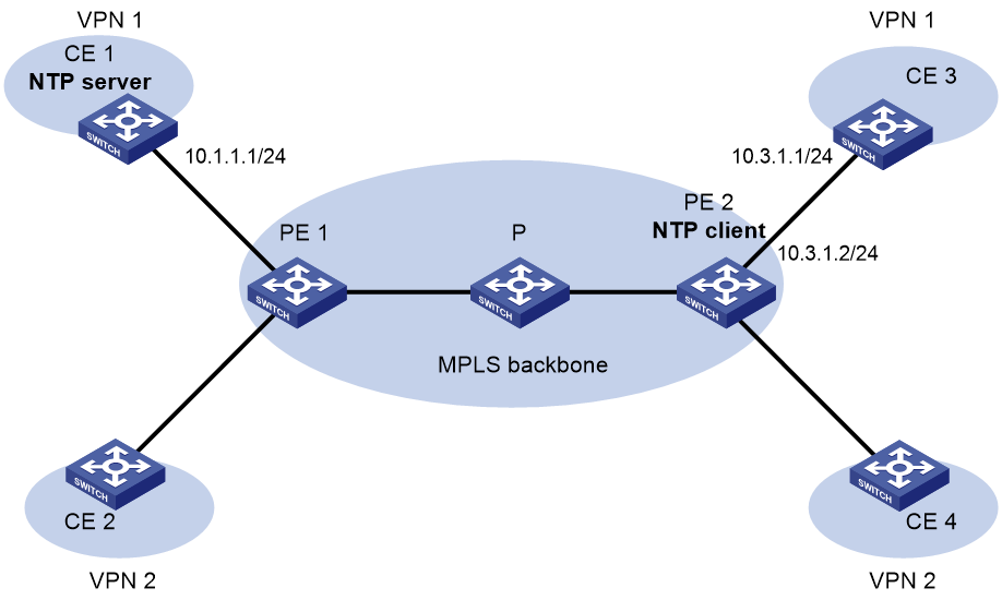
As shown in Figure 14, two MPLS L3VPN instances are present on PE 1 and PE 2: vpn1 and vpn2. CE 1 and CE 3 are devices in VPN 1.
To synchronize time between PE 2 and CE 1 in VPN 1, perform the following tasks:
· Configure CE 1's local clock as its reference source, with stratum level 2.
· Configure CE 1 in the VPN instance vpn1 as the NTP server of PE 2.
Procedure
Before you perform the following configuration, be sure you have completed MPLS L3VPN-related configurations. For information about configuring MPLS L3VPN, see MPLS Configuration Guide.
1. Assign an IP address to each interface, as shown in Figure 14. Make sure CE 1 and PE 1, PE 1 and PE 2, and PE 2 and CE 3 can reach each other. (Details not shown.)
2. Configure CE 1:
# Enable the NTP service.
<CE1> system-view
[CE1] ntp-service enable
# Specify the local clock as the reference source, with stratum level 2.
[CE1] ntp-service refclock-master 2
3. Configure PE 2:
# Enable the NTP service.
<PE2> system-view
[PE2] ntp-service enable
# Specify NTP for obtaining the time.
[PE2] clock protocol ntp
# Specify CE 1 in the VPN instance vpn1 as the NTP server of PE 2.
[PE2] ntp-service unicast-server 10.1.1.1 vpn-instance vpn1
Verifying the configuration
# Verify that PE 2 has synchronized to CE 1, with stratum level 3.
[PE2] display ntp-service status
Clock status: synchronized
Clock stratum: 3
System peer: 10.1.1.1
Local mode: client
Reference clock ID: 10.1.1.1
Leap indicator: 00
Clock jitter: 0.005096 s
Stability: 0.000 pps
Clock precision: 2^-22
Root delay: 0.00655 ms
Root dispersion: 1.15869 ms
Reference time: d0c62687.ab1bba7d Wed, Dec 29 2010 21:28:39.668
System poll interval: 64 s
# Verify that an IPv4 NTP association has been established between PE 2 and CE 1.
[PE2] display ntp-service sessions
source reference stra reach poll now offset delay disper
********************************************************************************
[1245]10.1.1.1 127.127.1.0 2 1 64 519 -0.0 0.0065 0.0
Notes: 1 source(master),2 source(peer),3 selected,4 candidate,5 configured.
Total sessions: 1
# Verify that server 127.0.0.1 has synchronized to server 10.1.1.1, and server 10.1.1.1 has synchronized to the local clock.
[PE2] display ntp-service trace
Server 127.0.0.1
Stratum 3 , jitter 0.000, synch distance 796.50.
Server 10.1.1.1
Stratum 2 , jitter 939.00, synch distance 0.0000.
RefID 127.127.1.0
Example: Configuring MPLS L3VPN network time synchronization in symmetric active/passive mode
Network configuration
As shown in Figure 15, two VPN instances are present on PE 1 and PE 2: vpn1 and vpn2. CE 1 and CE 3 belong to VPN 1.
To synchronize time between PE 1 and CE 1 in VPN 1, perform the following tasks:
· Configure CE 1's local clock as its reference source, with stratum level 2.
· Configure CE 1 in the VPN instance vpn1 as the symmetric passive peer of PE 1.
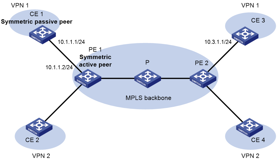
Procedure
Before you perform the following configuration, be sure you have completed MPLS L3VPN-related configurations. For information about configuring MPLS L3VPN, see MPLS Configuration Guide.
1. Assign an IP address to each interface, as shown in Figure 15. Make sure CE 1 and PE 1, PE 1 and PE 2, and PE 2 and CE 3 can reach each other. (Details not shown.)
2. Configure CE 1:
# Enable the NTP service.
<CE1> system-view
[CE1] ntp-service enable
# Specify NTP for obtaining the time.
[CE1] clock protocol ntp
# Specify the local clock as the reference source, with stratum level 2.
[CE1] ntp-service refclock-master 2
3. Configure PE 1:
# Enable the NTP service.
<PE1> system-view
[PE1] ntp-service enable
# Specify NTP for obtaining the time.
[PE1] clock protocol ntp
# Specify CE 1 in the VPN instance vpn1 as the symmetric passive peer of PE 1.
[PE1] ntp-service unicast-peer 10.1.1.1 vpn-instance vpn1
Verifying the configuration
# Verify that PE 1 has synchronized to CE 1, with stratum level 3.
[PE1] display ntp-service status
Clock status: synchronized
Clock stratum: 3
System peer: 10.1.1.1
Local mode: sym_active
Reference clock ID: 10.1.1.1
Leap indicator: 00
Clock jitter: 0.005096 s
Stability: 0.000 pps
Clock precision: 2^-22
Root delay: 0.00655 ms
Root dispersion: 1.15869 ms
Reference time: d0c62687.ab1bba7d Wed, Dec 29 2010 21:28:39.668
System poll interval: 64 s
# Verify that an IPv4 NTP association has been established between PE 1 and CE 1.
[PE1] display ntp-service sessions
source reference stra reach poll now offset delay disper
********************************************************************************
[1245]10.1.1.1 127.127.1.0 2 1 64 519 -0.0 0.0000 0.0
Notes: 1 source(master),2 source(peer),3 selected,4 candidate,5 configured.
Total sessions: 1
# Verify that server 127.0.0.1 has synchronized to server 10.1.1.1, and server 10.1.1.1 has synchronized to the local clock.
[PE1] display ntp-service trace
Server 127.0.0.1
Stratum 3 , jitter 0.000, synch distance 796.50.
Server 10.1.1.1
Stratum 2 , jitter 939.00, synch distance 0.0000.
RefID 127.127.1.0
Configuring SNTP
About SNTP
SNTP is a simplified, client-only version of NTP specified in RFC 4330. It uses the same packet format and packet exchange procedure as NTP, but provides faster synchronization at the price of time accuracy.
SNTP working mode
SNTP supports only the client/server mode. An SNTP-enabled device can receive time from NTP servers, but cannot provide time services to other devices.
If you specify multiple NTP servers for an SNTP client, the server with the best stratum is selected. If multiple servers are at the same stratum, the NTP server whose time packet is first received is selected.
Protocols and standards
RFC 4330, Simple Network Time Protocol (SNTP) Version 4 for IPv4, IPv6 and OSI
Restrictions and guidelines: SNTP configuration
When you configure SNTP, follow these restrictions and guidelines:
· You cannot configure both NTP and SNTP on the same device.
· To use NTP for time synchronization, you must use the clock protocol command to specify NTP for obtaining the time. For more information about the clock protocol command, see device management commands in Fundamentals Configuration Guide.
SNTP tasks at a glance
To configure SNTP, perform the following tasks:
2. Specifying an NTP server for the device
3. (Optional.) Configuring SNTP authentication
4. (Optional.) Specifying the SNTP time-offset thresholds for log and trap outputs
Enabling the SNTP service
Restrictions and guidelines
The NTP service and SNTP service are mutually exclusive. Before you enable SNTP, make sure NTP is disabled.
Procedure
1. Enter system view.
system-view
2. Enable the SNTP service.
sntp enable
By default, the SNTP service is disabled.
Specifying an NTP server for the device
Restrictions and guidelines
To use an NTP server as the time source, make sure its clock has been synchronized. If the stratum level of the NTP server is greater than or equal to that of the client, the client does not synchronize with the NTP server.
Procedure
1. Enter system view.
system-view
2. Specify an NTP server for the device.
IPv4:
sntp unicast-server { server-name | ip-address } [ vpn-instance vpn-instance-name ] [ authentication-keyid keyid | source interface-type interface-number | version number ] *
IPv6:
sntp ipv6 unicast-server { server-name | ipv6-address } [ vpn-instance vpn-instance-name ] [ authentication-keyid keyid | source interface-type interface-number ] *
By default, no NTP server is specified for the device.
You can specify multiple NTP servers for the client by repeating this step.
To perform authentication, you need to specify the authentication-keyid keyid option.
Configuring SNTP authentication
About this task
SNTP authentication ensures that an SNTP client is synchronized only to an authenticated trustworthy NTP server.
Restrictions and guidelines
Enable authentication on both the NTP server and the SNTP client.
Use the same authentication key ID, algorithm, and key on the NTP server and SNTP client. Specify the key as a trusted key on both the NTP server and the SNTP client. For information about configuring NTP authentication on an NTP server, see "Configuring NTP."
On the SNTP client, associate the specified key with the NTP server. Make sure the server is allowed to use the key ID for authentication on the client.
With authentication disabled, the SNTP client can synchronize with the NTP server regardless of whether the NTP server is enabled with authentication.
Procedure
1. Enter system view.
system-view
2. Enable SNTP authentication.
sntp authentication enable
By default, SNTP authentication is disabled.
3. Configure an SNTP authentication key.
sntp authentication-keyid keyid authentication-mode { hmac-sha-1 | hmac-sha-256 | hmac-sha-384 | hmac-sha-512 | md5 } { cipher | simple } string [ acl ipv4-acl-number | ipv6 acl ipv6-acl-number ] *
By default, no SNTP authentication key exists.
4. Specify the key as a trusted key.
sntp reliable authentication-keyid keyid
By default, no trusted key is specified.
5. Associate the SNTP authentication key with an NTP server.
IPv4:
sntp unicast-server { server-name | ip-address } [ vpn-instance vpn-instance-name ] authentication-keyid keyid
IPv6:
sntp ipv6 unicast-server { server-name | ipv6-address } [ vpn-instance vpn-instance-name ] authentication-keyid keyid
By default, no NTP server is specified.
Specifying the SNTP time-offset thresholds for log and trap outputs
About this task
By default, the system synchronizes the SNTP client's time to the server and outputs a log and a trap when the time offset exceeds 128 ms for multiple times.
After you set the SNTP time-offset thresholds for log and trap outputs, the system synchronizes the client's time to the server when the time offset exceeds 128 ms for multiple times, but outputs logs and traps only when the time offset exceeds the specified thresholds, respectively.
Procedure
1. Enter system view.
system-view
2. Specify the SNTP time-offset thresholds for log and trap outputs.
sntp time-offset-threshold { log log-threshold | trap trap-threshold } *
By default, no SNTP time-offset thresholds are set for log and trap outputs.
Display and maintenance commands for SNTP
Execute display commands in any view.
|
Task |
Command |
|
Display information about all IPv6 SNTP associations. |
display sntp ipv6 sessions |
|
Display information about all IPv4 SNTP associations. |
display sntp sessions |
SNTP configuration examples
Example: Configuring SNTP
Network configuration
As shown in Figure 16, perform the following tasks:
· Configure Device A's local clock as its reference source, with stratum level 2.
· Configure Device B to operate in SNTP client mode, and specify Device A as the NTP server.
· Configure NTP authentication on Device A and SNTP authentication on Device B.

Procedure
1. Assign an IP address to each interface, and make sure Device A and Device B can reach each other, as shown in Figure 16. (Details not shown.)
2. Configure Device A:
# Enable the NTP service.
<DeviceA> system-view
[DeviceA] ntp-service enable
# Specify NTP for obtaining the time.
[DeviceA] clock protocol ntp
# Configure the local clock as the reference source, with stratum level 2.
[DeviceA] ntp-service refclock-master 2
# Enable NTP authentication on Device A.
[DeviceA] ntp-service authentication enable
# Configure a plaintext NTP authentication key, with key ID of 10 and key value of aNiceKey.
[DeviceA] ntp-service authentication-keyid 10 authentication-mode md5 simple aNiceKey
# Specify the key as a trusted key.
[DeviceA] ntp-service reliable authentication-keyid 10
3. Configure Device B:
# Enable the SNTP service.
<DeviceB> system-view
[DeviceB] sntp enable
# Specify NTP for obtaining the time.
[DeviceB] clock protocol ntp
# Enable SNTP authentication on Device B.
[DeviceB] sntp authentication enable
# Configure a plaintext authentication key, with key ID of 10 and key value of aNiceKey.
[DeviceB] sntp authentication-keyid 10 authentication-mode md5 simple aNiceKey
# Specify the key as a trusted key.
[DeviceB] sntp reliable authentication-keyid 10
# Specify Device A as the NTP server of Device B, and associate the server with key 10.
[DeviceB] sntp unicast-server 1.0.1.11 authentication-keyid 10
Verifying the configuration
# Verify that an SNTP association has been established between Device B and Device A, and Device B has synchronized its time with Device A.
[DeviceB] display sntp sessions
NTP server Stratum Version Last receive time
1.0.1.11 2 4 Tue, May 17 2011 9:11:20.833 (Synced)