- Table of Contents
- Related Documents
-
| Title | Size | Download |
|---|---|---|
| 01-text | 3.51 MB |
Contents
Preparing for compute virtualization deployment
Selecting a deployment mode for the management node
Planning external storage connection
Installing the UIS HCI software
Obtaining the ISO image file of UIS Manager
Installing the UIS HCI software
Accessing UIS Manager for the first time
Configuring management interface parameters
Launching the UIS Setup Wizard
Deploying UIS Manager in the compute virtualization scenario
Deploying UIS Manager in the HCI scenario
About UIS Manager
H3C UIS Manager is a resource management platform developed for cloud computing and virtualization in cloud data centers to deliver IaaS. It provides management of compute, network, and storage resource virtualization from a simplified GUI, and provisions resources for applications.
UIS Manager provides the following functions:
· Unified management of physical and virtual resources.
· Automated orchestration of virtual compute and storage resources.
· Distributed storage configuration and monitoring.
· Management of virtual network policies.
· Management of virtual security resources.
· Peripheral GPU resource pool management.
· One-key operation and maintenance.
· Open APIs.
This document describes the procedure for installing and initializing UIS Manager. Use this document when you install, reinstall, or initialize UIS Manager.
|
|
CAUTION: Reinstalling UIS Manager on a host might affect services on the other hosts in the cluster. Before reinstalling UIS Manager, first remove the host from the cluster. |
Preparing for installation
UIS Manager allows you to deploy compute virtualization and hyper-converged infrastructure (HCI) on hosts.
· Compute virtualization—Deploys only Cloud Virtualization Kernel (CVK) and provides storage services through an IP SAN or FC SAN. A minimum of one host is required. All hosts form a UIS compute virtualization cluster after the deployment.
· HCI—Deploys both CVK and distributed storage. A minimum of two hosts are required. All hosts form a UIS HCI cluster after the deployment.
|
|
NOTE: Unless otherwise stated, a host in this guide refers to a server. |
Preparing for compute virtualization deployment
Hardware requirements
A minimum of one server is required for compute virtualization deployment. Table 34 describes the hardware requirements for a server for compute virtualization deployment.
Table 34 Hardware requirements for a server
|
Item |
Minimum requirements |
|
CPU |
Base frequency: 2 GHz NOTE: Make sure the CPUs support Intel-VT. |
|
Memory |
32 GB |
|
System disks |
Two 300 GB HDDs |
|
NICs |
One 4-port GE NIC |
|
|
IMPORTANT: · To deploy compute virtualization on an x86 server, make sure the server supports Intel virtualization technology (Intel-VT). Intel-VT can virtualize one physical CPU into multiple CPUs, with each running its own operating system. · To deploy compute virtualization on an ARM server, make sure the server supports the ARM Virtualization Host Extensions (VHE) technology. · The physical resources on the server must be sufficient to support the VMs running on the server. |
Determining host roles
A compute virtualization cluster requires a management node and multiple service nodes. A host can operate as a management node or service node or both. When planning the host roles, take the deployment mode (see "Selecting a deployment mode for the management node") also in consideration.
· Management node—Manages and maintains the entire compute virtualization system. Before deployment, you must specify a server as the management node and assign a management IP address to it. Make sure the IP address is accessible to the management PC.
· Service node—Provides computing services.
Selecting a deployment mode for the management node
Two management node deployment modes are available for compute virtualization setup:
· Converged deployment—The management node operates on the same host as a service node.
· Distributed deployment—The management node operates on a different host than a service node.
As a best practice, use converged deployment when the number of hosts is less than 16 and use distributed deployment when the number of hosts is equal to or great than 16.
Planning the networks
To achieve compute virtualization, plan the networks as follows:
· Management network—Transmits data between the UIS Manager and the control layer of each host. Users access the management network to manage UIS service nodes. Use GE or 10-GE connections to set up the management network.
· Storage network—Transmits data packets and management packets between hosts and storage servers of IP SAN or FC SAN. Use 10-GE or FC connections to set up a storage network.
· Service network—Transmits VM service data. Use GE or 10-GE connections to set up the service network.
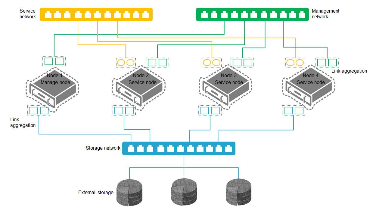
Network topologies
Use the topology in Figure 69 or Figure 70 as a best practice. You can adjust the topology according to the actual network environment and number of hosts.
As a best practice, use different physical NICs for the management and service networks.
Figure 69 Network topology for converged deployment

Figure 70 Network topology for distributed deployment
|
|
NOTE: In distributed deployment, no service network is required for the management node. |
Network planning example
The example network port configurations for IP SAN storage and FC SAN storage are shown in Table 35 and Table 36, respectively.
Table 35 Port planning example for IP SAN storage
|
Item |
NICs |
Port configurations |
|
Scheme 1 |
1 × 4-port GE NIC 1 × 2-port 10-GE NIC |
· Management network: 2 × GE ports enabled with link aggregation · Service network: 2 × GE ports enabled with link aggregation · IP SAN storage network: 2 × 10-GE ports enabled with link aggregation |
|
Scheme 2 |
2 × 2-port 10-GE NICs |
· Management and service networks: Share two 10-GE ports enabled with link aggregation · IP SAN storage network: 2 × 10-GE ports enabled with link aggregation |
Table 36 Port planning example for FC SAN storage
|
Item |
NICs |
Port configurations |
|
Scheme 1 |
1 × 4-port GE NIC 1 × 2-port FC HBA |
· Management network: 2 × GE ports enabled with link aggregation · Service network: 2 × GE ports enabled with link aggregation · FC SAN storage network: 2 × FC ports enabled with link aggregation |
|
Scheme 2 |
1 × 2-port GE NIC 1 × 2-port FC HBA |
· Management and service networks: Share two 10-GE ports enabled with link aggregation · FC SAN storage network: 2 × FC ports enabled with link aggregation |
Table 37 Network segment planning example
|
Logical network |
IP address |
Gateway |
VLAN |
|
iLO management network |
192.168.1.0/24 |
192.168.1.154 |
10 |
|
Management network |
172.20.1.0/24 |
172.20.100.254 |
11 |
|
IP SAN storage network |
10.10.11.0/24 |
10.10.11.254 |
12 |
|
Service network |
192.170.1.0/24 |
192.170.1.254 |
13 |
Table 38 IP address planning example
|
Host role |
iLO NIC (VLAN 10) |
Management NIC (VLAN 11) |
IP SAN storage NIC (VLAN 12) |
Service NIC (VLAN 13) |
|
Management node |
192.168.1.1 |
172.20.1.1 |
10.10.11.1 |
· Converged deployment: Optional · Distributed deployment: N/A |
|
Service node 1 |
192.168.1.2 |
172.20.1.2 |
10.10.11.2 |
Optional |
|
Service node 2 |
192.168.1.3 |
172.20.1.3 |
10.10.11.3 |
Optional |
|
Service node 3 |
192.168.1.4 |
172.20.1.4 |
10.10.11.4 |
Optional |
Planning external storage connection
To connect the hosts to IP SAN or FC SAN devices, follow these restrictions and guidelines:
· For a host to access an IP SAN storage device, use the host's iSCSI Qualified Name (IQN) to connect the host to the iSCSI target. An IQN is generated after you launch the UIS Setup Wizard. You can modify IQNs from the UIS Manager.
· For a host to access an FC SAN storage device, install an FC HBA on the server.
· A host can access volumes in an IP SAN or FC SAN through multiple methods. As a best practice, format volumes into a shared file system to provide conflict-free concurrent access.
· An iSCSI/FC shared file system can be used by a maximum of 32 hosts in a cluster.
· An iSCSI/FC shared file system supports a maximum of 32 TB in size. As a best practice, use a volume of 10 to 32 TB as the shared file system.
Configuring NTP settings
All nodes in a cluster must use the same system time. By default, the management node acts as an NTP server to synchronize time settings to all the service nodes in the cluster.
If a standalone NTP server is available, you can configure nodes in the cluster to synchronize time settings from the NTP server. Make sure the nodes in the management network can reach the NTP server. For more information, see "Specifying NTP servers."
Preparing for HCI deployment
Hardware requirements
A minimum of three servers are required for HCI deployment. Table 39 describes the hardware requirements for a server for HCI deployment.
Table 39 Hardware requirements for a server
|
Item |
Minimum requirements |
|
CPU |
Frequency: 2 GHz NOTE: Make sure the CPUs support Intel-VT. |
|
Memory |
128 GB |
|
System disks |
Two 300 GB or larger HDDs |
|
Disks for distributed storage |
≥ 2 |
|
NIC |
One 4-port GE NIC + one 2-port 10-GE NIC |
|
Storage controllers |
2 G cache |
|
|
IMPORTANT: · For HCI deployment on an x86 server, make sure the server supports Intel virtualization technology (Intel-VT). Intel-VT can virtualize one physical CPU into multiple CPUs, with each running its own operating system. · For HCI deployment on an ARM server, make sure the server supports the ARM Virtualization Host Extensions (VHE) technology. · The physical resources on the server must be sufficient to support the VMs running on the server. |
Determining host roles
An HCI cluster requires a management node and multiple service nodes. A host can operate as a management node or service node or both. When planning the host roles, take the deployment mode (see "Selecting a deployment mode") also in consideration.
· Management node—Manages and maintains the entire HCI system. Before deployment, you must specify a server as the management node and assign a management IP address to it.
· Service node—Provides computing and storage services.
To deploy distributed storage, two types of services nodes are required.
· Storage node—Provides storage resources. A minimum of two storage nodes are required.
· Monitor node—Monitors the entire storage system and maintains and distributes various information vital to storage system operations. The storage nodes and monitor nodes are deployed on the same host. As a best practice, use the following numbers of monitor nodes:
¡ 2 to 4 storage nodes—3.
¡ 5 to 10 storage nodes—5.
¡ Over 10 storage nodes—7.
Selecting a deployment mode
Two deployment modes are available for HCI setup.
· Converged deployment—The management node operates on the same host with a service node.
· Distributed deployment—The management node operates on a different host than a service node.
As a best practice, use converged deployment when the number of hosts is less than 16 and use distributed deployment when the number of hosts is equal to or great than 16.
Planning the networks
To set up the UIS HCI system, plan the networks as follows:
· Management network—Transmits data between UIS Manager and the control layer of each host. Users access the management network to manage UIS service nodes. Use GE or 10-GE connections to set up the management network.
· Service network—Transmits VM service data. Use GE or 10-GE connections to set up the service network.
· Storage front-end network—Forwards traffic between VMs and the distributed storage cluster. Use 10-GE connections to set up the storage front-end network.
· Storage back-end network—Forwards internal traffic in the distributed storage cluster. Use 10-GE connections to set up the storage back-end network.
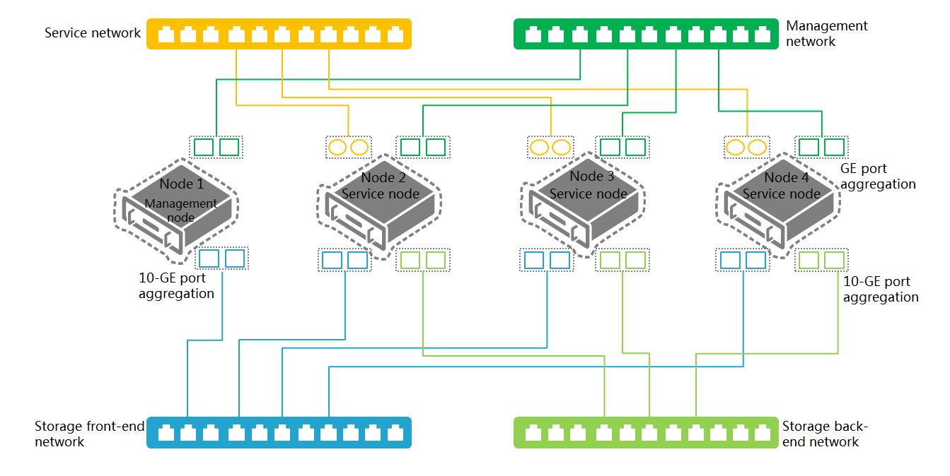
Network planning
Figure 71 and Figure 72 display the recommended converged deployment and distributed deployment network topologies, respectively.
Figure 71 Deployment on three or more hosts (converged deployment)
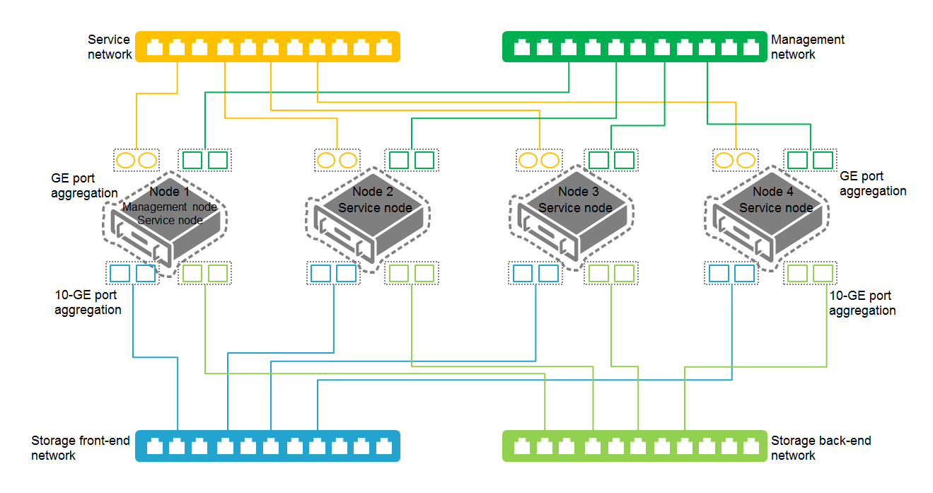
Figure 72 Deployment on three or more hosts (distributed deployment)
|
|
NOTE: In distributed deployment, you must connect the management node to the management network and the storage front-end network. The service network and storage back-end network are not required for the management node. |
|
|
IMPORTANT: · Use the recommended topology as a best practice. You can adjust the topology according to the actual network environment and number of servers. · As a best practice, deploy the management network, storage front-end network, and storage back-end network on different ports. If a separate port is not available, these networks can share a port. |
Table 40 Port planning example
|
Item |
NICs |
Port configurations |
|
Scheme 1 |
1 × 4-port GE NIC 2 × 2-port 10-GE NICs |
· Management network: 2 × GE ports enabled with link aggregation · Service network: 2 × GE ports enabled with link aggregation · Storage front-end network: 2 × 10-GE ports enabled with link aggregation · Storage back-end network: 2 × 10-GE ports enabled with link aggregation |
|
Scheme 2 |
1 × 4-port GE NIC 1 × 2-port 10-GE NIC |
· Management network: 2 × GE ports enabled with link aggregation · Service network: 2 × GE ports enabled with link aggregation · Storage front-end and back-end networks: Share two 10-GE ports enabled with link aggregation |
|
Scheme 3 |
2 × 2-port 10-GE NICs |
· Management and service networks: 2 × GE ports enabled with link aggregation · Storage front-end and back-end networks: Share two 10-GE ports enabled with link aggregation |
Network planning example
Table 41 Network segment planning example
|
Logical network |
IP address |
Gateway |
VLAN |
|
iLO management network |
172.88.211.0/16 |
172.20.0.254 |
9 |
|
Management network |
172.88.111.0/16 |
172.88.0.254 |
10 |
|
Service network |
192.168.1.0/24 |
192.168.1.254 |
11 |
|
Storage front-end network |
10.10.9.0/24 |
10.10.9.254 |
12 |
|
Storage back-end network |
10.10.10.0/24 |
10.10.10.254 |
13 |
Table 42 IP address planning example
|
Host role |
iLO NIC (VLAN 9) |
Management NIC (VLAN 10) |
Storage front-end network NIC (VLAN 12) |
Storage back-end network NIC (VLAN 13) |
Service NIC (VLAN 11) |
|
Management node |
172.88.211.83 |
172.88.111.83 |
10.10.9.1 |
· Converged deployment: 10.10.10.1 · Distributed deployment: N/A |
· Converged deployment: Optional · Distributed deployment: N/A |
|
Service node 1 |
172.88.211.84 |
172.88.111.84 |
10.10.9.2 |
10.10.10.2 |
Optional |
|
Service node 2 |
172.88.211.85 |
172.88.111.85 |
10.10.9.3 |
10.10.10.3 |
Optional |
|
Service node 3 |
172.88.211.86 |
172.88.111.86 |
10.10.9.4 |
10.10.10.4 |
Optional |
|
Service node 4 |
172.88.211.87 |
172.88.111.87 |
10.10.9.5 |
10.10.10.5 |
Optional |
|
|
IMPORTANT: The system requires you to specify the start IP address for the management node at deployment. The system automatically assigns the available IP addresses with an increment of 1 of the start IP address to service nodes. You can also manually specify IP addresses for service nodes. The specified IP addresses must be higher than the start IP address. Reserve IP address resources for future expansion. |
Planning distributed storage
Planning deployment modes
The following storage deployment modes are available:
· SSD caches+HDDs—Deploy HDDs as data disks to store data and deploy SSDs as cache disks to accelerate reads and writes. The required SSDs depend on the SSD type:
¡ If SATA SSDs are used, make sure the ratio of SSDs and HDDs ≥ 1: 5.
¡ If NVMe SSDs are used, make sure the ratio of SSDs and HDDs ≥ 1: 10.
· All SSDs—Deploy SSDs as data disks to store data without using data caches. Use this mode to provide high-performance storage services.
· All HDDs—Deploy HDDs as data disks to store data without using data caches. Use this mode to provide normal storage services.
· HDDs+SSDs—Deploy SSDs and HDDs as data disks in high-performance storage pools and slow-performance storage pools, respectively, to provide storage services for applications that require different storage performance.
For more information about the number of required disks on each host, see "Planning storage."
Planning replicas
The system protects data by creating multiple replicas of data distributed in different fault domains. Data is available as long as one fault domain is operating correctly with the replica in the domain being integrated.
Table 43 displays the available number of replicas for different storage node configurations.
Table 43 Available replicas for different storage node configurations
|
Storage node quantity |
Number of replicas |
|
2 |
2 |
|
3 |
2 or 3 |
|
4 |
2, 3, or 4 |
|
5 |
2, 3, 4, or 5 |
|
≥ 6 |
2, 3, 4, or 5 |
|
|
IMPORTANT: Creating more replicas provides higher fault tolerance. For important services, create three replicas as a best practice. |
Planning racks
As a best practice, create racks based on the actual rack mounting conditions of the hosts, and install a minimum of two storage nodes in each rack.
You can install a maximum of 10 storage nodes in a rack.
Planning fault domains
A fault domain is a set of hardware components that share a single point of failure. To be fault tolerant to a certain level, data must be distributed across multiple fault domains at that level.
The following fault domain levels are available:
· Rack level—Each rack is a fault domain. The system preferentially distributes replicas or fragments of data across multiple racks.
· Host level—Each host is a fault domain. The system preferentially distributes replicas or fragments of data across multiple hosts.
Planning CPUs
|
|
IMPORTANT: · Reserve CPU resources for other non-storage services such as VMs. · As a best practice, use CPUs of the same model in HCI deployment. |
Table 44 Planning CPUs
|
Node type |
Minimum requirements |
|
Management node |
4 GHz. |
|
Storage node |
1 GHz per data disk in each storage node. |
|
Monitor node |
2 GHz. |
|
Storage node that also acts as the management node, a monitor node, or both |
Sum of the required resources for each node type. For example, if a storage node that also acts a management node and monitor node has 10 HDDs deployed as data disks, assign a minimum of 16 GHz CPU resources to the node. |
|
|
NOTE: CPU resource=CPU base frequency × CPUs × CPU cores per CPU. |
Planning memory
|
|
IMPORTANT: Reserve memory resources for other non-storage services such as VMs. |
Table 45 Planning memory
|
Node type |
Minimum requirements |
|
Management node |
32 GB (a minimum of 8 GB for distributed storage). |
|
Storage node |
· 1 GB per data disk. · 1 GB per 1 TB data disk. For example, if a storage node contains ten 4 TB data disks (40 TB storage space), assign 40 GB memory to the node. · 0.5 times the total memory size for data disks and storage space for the data buffer. |
|
Monitor node |
1 GB. |
|
Storage node that also acts as the management node, a monitor node, or both |
Sum of the required resources for each node type. For example, if a storage, manage, and monitor node has ten 4 TB HDD data disks, assign memory resources for the node as follows: · Management node—32 GB. · Data disks—10 GB (10 × 1 GB). · Storage space—40 GB (10 × 4 × 1 GB). · Data buffer—25 GB ((10 + 40) × 0.5). · Monitor node—1 GB. · Total—Over 108 GB (32 + 10 + 40 + 25 + 1 + reserved resources).
Plan a minimum of 128 GB memory for each host even if the calculated total value is less than 128 GB. |
Planning storage
|
System disks (required on each node) |
|||||||||
|
Min. system disks |
2 |
||||||||
|
Minimum requirements: SAS disks at 10000 rpm (or higher) Recommended: SSDs NOTE: Do not configure LVM for system disks. |
|||||||||
|
RAID level |
RAID 1 on a minimum of two disks. |
||||||||
|
Minimum data capacity |
The free system disk capacity after operating system installation must meet the following requirements: · Management node: 50 GB. · Storage or monitor node: 20 GB · Manage, storage, and monitor nodes: 90 GB (50 + 20 + 20) |
||||||||
|
Data disks (required on storage nodes) |
|||||||||
|
Min. data disks |
2 |
||||||||
|
Disk types |
Disks at 10000 rpm (or higher). You can use disks whose disk drive letter starts with string sd, df, or nvme as data disks.
Do not use read-intensive SSDs as data disks, Intel S3500 series SSDs for example. Disable disk caching on all hosts. Make sure disks in a disk pool have the same capacity and rotation speed. |
||||||||
|
Disk consistency |
As a best practice, use disks of the same capacity and same type across all storage nodes. As a best practice, install the same number of data disks on every host. If you have to install different numbers of data disks, make sure the difference between the largest quantity and the smallest quantity does not exceed 20% of the largest quantity. |
||||||||
|
RAID level |
RAID 0 on each disk. |
||||||||
|
SSD caches (available only for SSD caches+HDDs deployment) |
|||||||||
|
Cache settings cannot be modified after UIS setup finishes. If the storage cluster deployment mode is SSD caches+HDDs, you must deploy HDDs as data disks, deploy SSDs as read or write caches, and specify a cache partition for each HDD. |
|||||||||
|
Min. SSDs |
For SATA SSDs, a minimum of one-fifth the number of HDDs is required. For NVMe SSDs, a minimum of one-tenth the number of HDDs is required.
To avoid storage performance degradation or cluster errors, do not configure SSD caches if the number of SSDs does not reach the requirement. |
||||||||
|
Disk types |
Do not use read-intensive SSDs Intel S3500 series SSDs for example, as read or write caches. |
||||||||
|
Cache partitions |
Size of each partition: Total size of SSDs deployed as caches divided by the number of HDDs For example, if 10 HDDs and 2 SSDs exist and the total size of SSDs deployed as caches is 450 GB, you can assign about 90 GB (450 GB multiplied by 2 and then divided by 10) to each cache partition (without regard to future expansion).
Make sure the size of each cache partition multiplied by the number of data disks on a storage node is smaller than the total size of SSDs deployed as caches. If HDD expansion is required, reserve SSD space in storage planning. As a best practice, set large write or read cache partitions if SSD caches are large enough. Typically, the actual size of a disk is smaller than the claimed size. Please use the actual size to plan storage. For illustration purposes, this document uses the claimed size. Disable disk caching on all nodes. For the UIS HCI series, disk caching is disabled by default. For a non-UIS HCI device, disable disk caching manually. |
||||||||
|
RAID level |
0 on each disk. For the UIS HCI series, the RAID level is set to 0 by default. For a non-UIS HCI device, set the RAID level to 0 manually. |
||||||||
|
RAID controller |
Required. The RAID controller must operate in MaxPerformance mode. The RAID controller must have a built-in cache module and have been connected to a supercapacitor. When the cache's battery or supercapacitor is not in place or is not fully charged, disable the cache from the RAID controller configuration tool.
Before installing a RAID controller, make sure the RAID controller is compatible with the server. For the compatibility information, see the most recent version of H3C UIS Software and Hardware Compatibility. |
||||||||
|
Caching |
|||||||||
|
Disk caching is disabled for the UIS HCI series by default. |
|||||||||
|
Item |
SSD system disks |
HDD system disks |
SSD caches |
HDD data disks |
SSD data disks |
||||
|
Disk caching |
Disabled |
Disabled |
Disabled |
Disabled |
Disabled |
||||
|
RAID controller read caching |
Disabled |
Enabled |
Disabled |
Enabled |
Disabled |
||||
|
Disabled |
Enabled |
Disabled |
Enabled |
Disabled |
|||||
|
Required HDDs and SSDs on each host in HIC deployment on three or more hosts |
|||||||||
|
Deployment mode |
System disks |
Cache disks |
Data disks |
Total disks |
|||||
|
SSD caches+HDDs |
2 HDDs |
≥ 1 SSD |
≥ 2 HDDs |
≥ 5 |
|||||
|
All SSDs |
2 HDDs |
N/A |
≥ 2 SSDs |
≥ 4 |
|||||
|
All HDDs |
2 HDDs |
N/A |
≥ 2 HDDs |
≥ 4 |
|||||
|
HDDs+SSDs |
2 HDDs |
N/A |
≥ 2 HDDs or SSDs |
≥ 4 |
|||||
Configuring NTP settings
All nodes in a cluster must use the same system time. By default, the management node acts as an NTP server to synchronize time settings to all the service nodes in the cluster.
If a standalone NTP server is available, you can configure nodes in the cluster to synchronize time settings from the NTP server. Make sure the nodes in the management network can reach the NTP server. For more information, see "Specifying NTP servers."
Installing the UIS HCI software
The UIS HCI software contains the hyper-converged kernel and the UIS Manager. The hyper-converged kernel is embedded with the H3C CAS computing virtualization software, H3C ONEStor software, and UIS-Sec network and security virtualization software. UIS Manager is available only when the hyper-converged kernel is installed.
The UIS HCI series is shipped with the HCI software installed. You are required to install the HCI software in the following scenarios:
· You are to reinstall the software for a UIS HCI device.
· A non-UIS HCI device requires installation of UIS HCI software.
|
|
NOTE: Before deploying software on a server, connect a monitor, keyboard, and mouse to it. |
Restrictions and guidelines
You must install the UIS software on every host. The host you use to launch the UIS Setup Wizard is the management node.
Prerequisites
Obtaining the ISO image file of UIS Manager
UIS Manager ISO image file is available in the following versions:
· Auto installation version—Enables the system to scan present disks by disk type and use the disks with the first available type as the system disk and configure disk partitions automatically. NVMe disks, USB disks, and FC disks will not be used. The image file for this version has AUTO in its name, for example, H3C_UIS-E0712-AUTO.iso. As a best practice, use the auto installation version.
· Manual installation version—Allows you to specify the type of disks to be used as the system disk and configure the size of each disk partition. The image file for this version does not have AUTO in its name, for example, H3C_UIS-E0712.iso. If you use the manual installation version, make sure the size of each partition is as required in Table 46.
Table 46 Partition descriptions and specifications
|
Partition |
Description |
Min. size |
Recommended max. size |
|
/boot/efi (boot partition) |
Stores all boot files of the system. |
512 MB |
512 MB |
|
/ (root partition) |
Stores all directories of the system. Users can access all directories from this partition. |
102400 MB |
204800 MB |
|
/var/log (log partition) |
Stores log files about system operations. |
20480 MB |
51200 MB |
|
swap (swap partition) |
Stores data temporarily when the system memory is insufficient. This partition is accessible only for the system. |
4096 MB |
32 GB |
|
/vms (VM data partition) |
Stores all data files of VMs. |
1024 MB |
No limit |
You can use a USB drive or virtual CD-ROM on the server for installing the UIS HCI software. As a best practice, use a USB drive for installation. This document installs the software by using a USB drive.
|
|
IMPORTANT: · To use the CD-ROM for installing the software, access the remote console through Java KVM. Ensure stable network connectivity during installation. · To use NVMe disks as the system disk, configure RAID settings on the disks before installation and use a manual installation version. As a best practice, use two NVMe disks and configure RAID 1. To configure RAID 1 for NVMe disks, you must install an NVMe VROC module on the server. · Make sure devices in the same cluster use the same ISO image file. · To configure stateful failover, make sure the two devices that form a stateful failover system have the same system disk configurations. As a best practice, use an auto installation version if stateful failover is configured. · To use a third-party server or a server that uses a RAID controller not in the compatible controller list, configure RAID settings on the server before installation. |
Creating a bootable USB drive
The server provides multiple USB ports. You can create a bootable USB drive from an ISO image file and use the USB drive to install the system.
Configuring BIOS settings
Enable hardware-assisted virtualization from the BIOS. Then save BIOS settings and restart the host. For more information about the BIOS, see the user guide for the host.
Configuring RAID settings
You do not need to configure RAID settings for a UIS HCI device. RAID settings are automatically configured during the UIS manager deployment process.
For a non-HCI device, configure RAID settings on the device and disable physical disk caching before installation.
To reinstall the software on a host, first delete the RAID settings on the host and format the system disk.
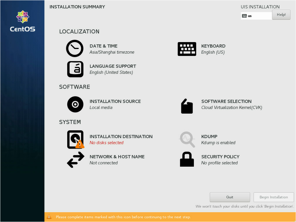
Installing the UIS HCI software
1. Insert the USB bootable drive into a USB port on the server. Then, start the server and select booting up from the USB drive.
|
|
IMPORTANT: If the server has NVMe drives, you must set server boot mode to UEFI rather than Legacy. |
Figure 73 INSTALLATION SUMMARY page
2. Select the system disk.
a. Click INSTALLATION DESTINATION in the SYSTEM area.
Figure 74 INSTALLATION DESTINATION page
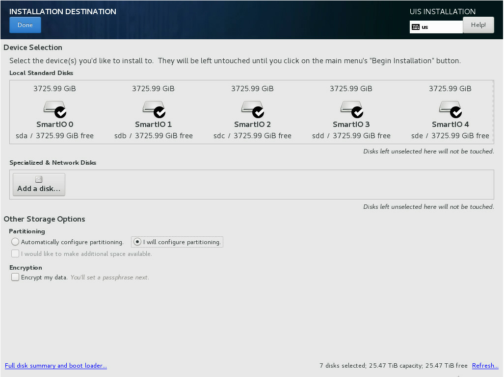
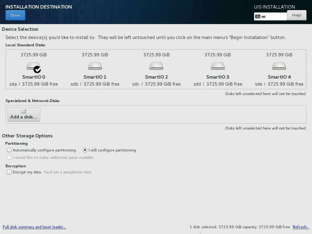
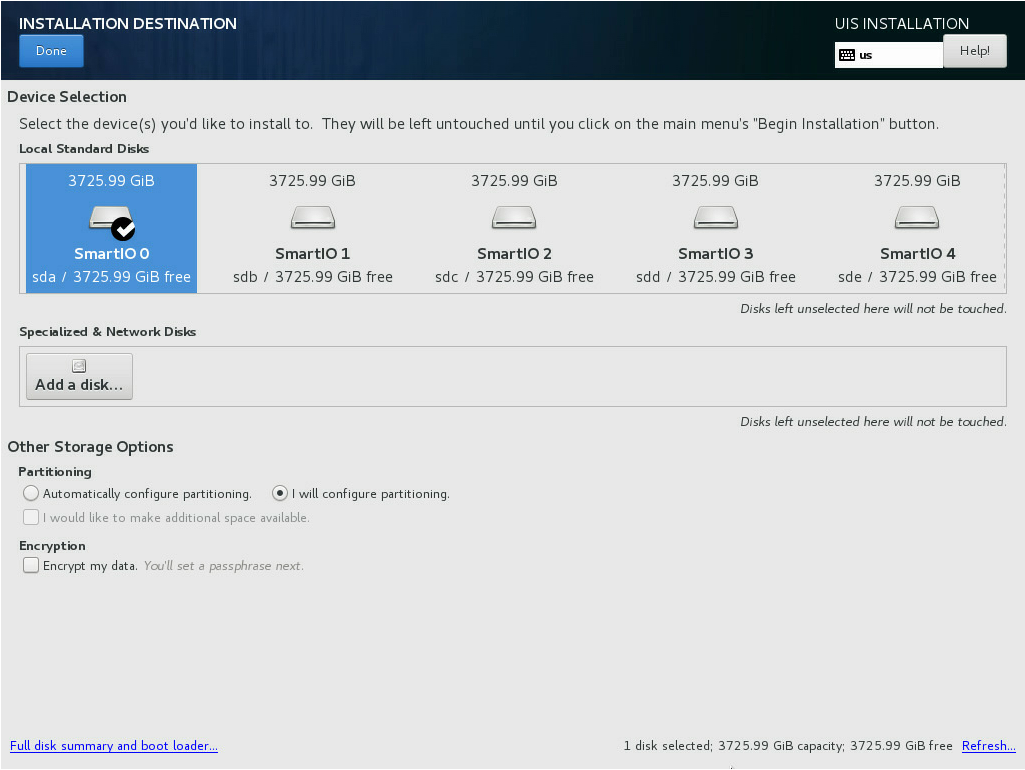
b. In the Local Standard Disks area, deselect the disks on which you are not to install the system. Leave one disk selected to install the system.
Figure 75 Selecting the disk to install the system
3. (Optional.) Perform automatic disk partitioning.
The disk to install the UIS Manager can be partitioned automatically or manually. If there are no special restrictions on partition sizes, perform automatic disk partitioning as a best practice.
To perform automatic disk partitioning:
a. On the INSTALLATION DESTINATION page, select Automatically configure partitioning in the Partitioning area.
Figure 76 Selecting automatic disk partitioning

b. Click Done in the top left corner.
The system returns to the INSTALLATION SUMMARY page when the partitioning is complete.
Figure 77 Returning to the INSTALLATION SUMMARY page

4. (Optional.) Partition the disk manually.
a. On the INSTALLATION DESTINATION page, select I will configure partitioning in the Partitioning area. Then click Done in the top left corner.
Figure 78 Selecting manual disk partitioning
b. On the MANUAL PARTITIONING page, click the ![]() button.
button.
Figure 79 MANUAL PARTITIONING page
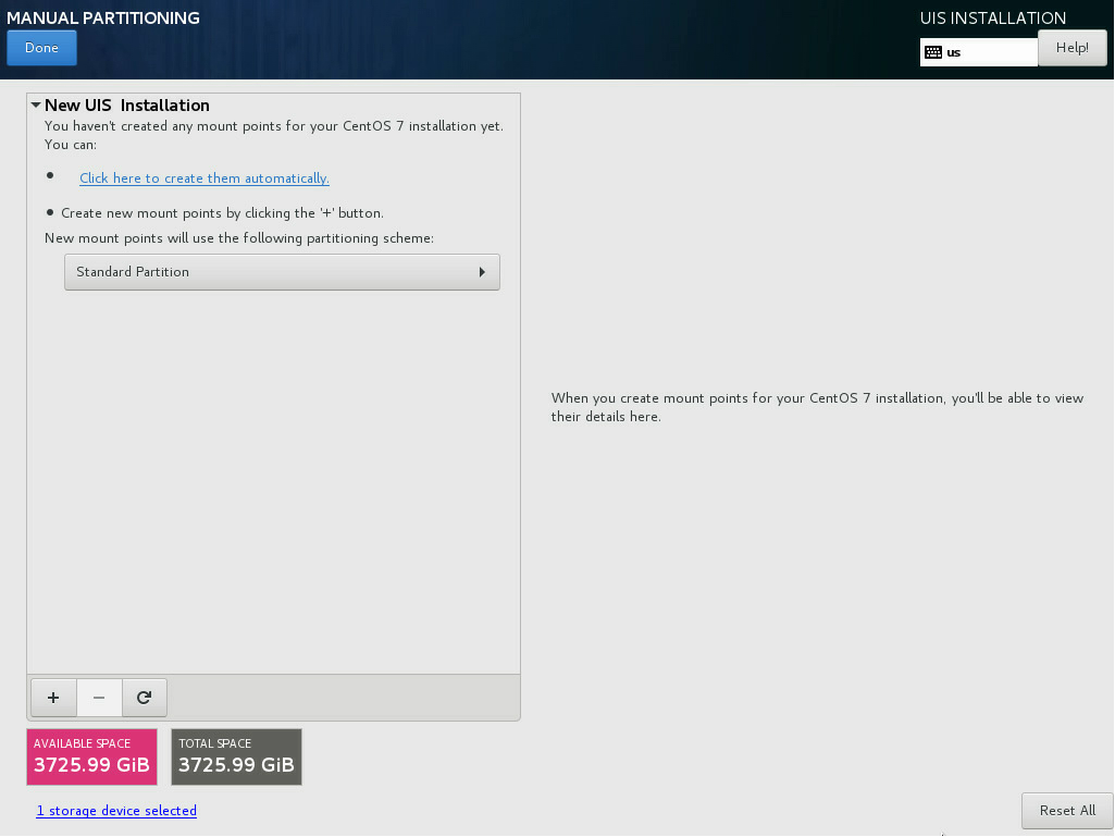
c. In the dialog box that opens, select a partition from the Mount Point list and set a capacity for it. Then click Add mount point. Add the /, /boot/efi, swap, /vms, and /var/log partitions in turn.
See Table 46 for the partition descriptions and specifications.
Figure 80 Adding a new mount point
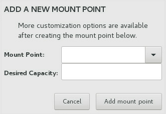
Figure 81 shows the sample partitioning information when the partitioning is complete.
Figure 81 Partitioning information

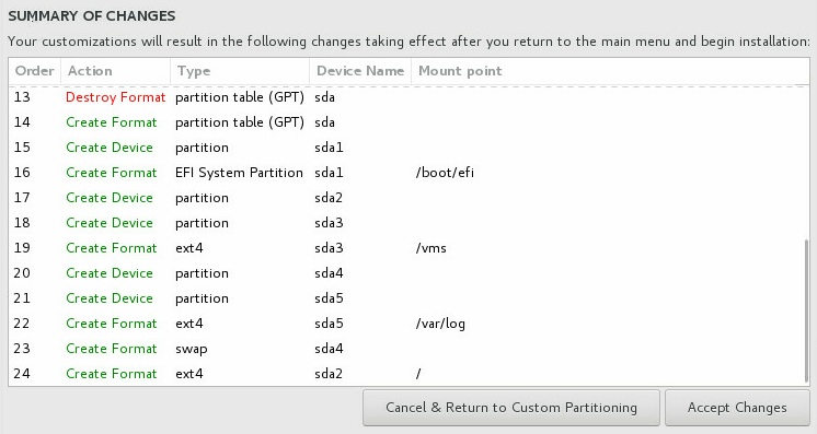
d. Click Done in the top left corner.
e. In the dialog box that opens, click Accept Changes to confirm the partitioning.
Figure 82 Confirming the partitioning
5. On the INSTALLATION SUMMARY page, retain the default settings for other configuration items and click Begin Installation.
After the installation is complete, the server restarts automatically and opens the Configuration screen.
Figure 83 Host configuration screen
|
|
NOTE: If a DHCP server exists in the management network, the server obtains an IP address from the DHCP server automatically. If no DHCP server exists in the management network, all management network parameters on the Configuration screen are empty. |
Accessing UIS Manager for the first time
After UIS Manager installation, you must launch the UIS Setup Wizard on the planned management node for the node to detect and manage all the other nodes.
Configuring management interface parameters
If no DHCP server is available in the management network, configure management interface parameters for the management node. You can configure the parameters for the other nodes as needed.
To configure management interface parameters for a server:
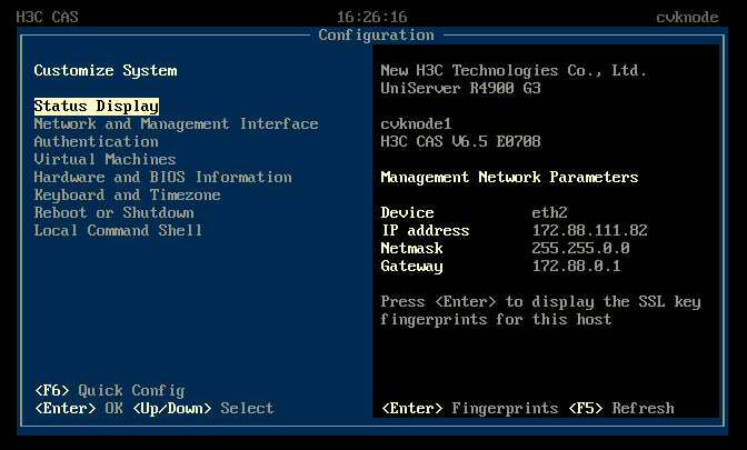
1. Access the server and then access the Configuration screen.
Figure 84 Configuration screen

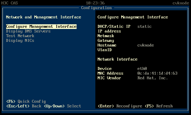
2. Select Network and Management Interface > Configure Management Interface.
Figure 85 Configure Management Interface screen
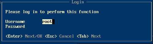
3. Enter the password of the root user. By default, the password is Sys@1234.
|
|
NOTE: In a version earlier than UIS-E0715, the default password of the root user is root. |
Figure 86 Login screen
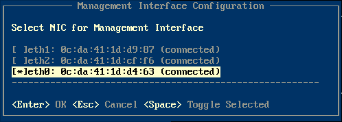
4. Select a NIC as the management network interface and then press Enter. The physical status of the selected NIC must be connected.
|
|
IMPORTANT: Select two NICs if link aggregation has been configured for the management network. |
Figure 87 Selecting a NIC
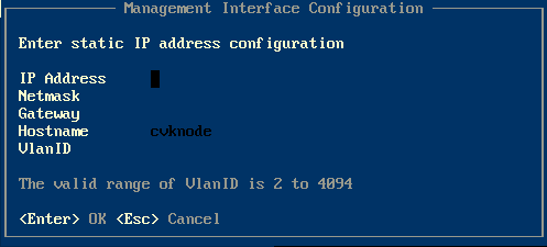
5. Enter the IP address, netmask, gateway address, hostname, and VLAN ID for the management interface as needed, and then press Enter.
Figure 88 Configuring management interface parameters
Logging in to UIS Manager
1. Access the UIS Manager login page at http://manage_node_management_IP:8080 or https://manage_node_management_IP:8443.
manage_node_management_IP represents the management interface IP address of the management node. For more information, see "Configuring management interface parameters."
|
|
NOTE: As a best practice, use Chrome 55+, Firefox 49+, or a browser of a higher version, and set the resolution to 1440*900 or higher. |
Figure 89 UIS Manager login page
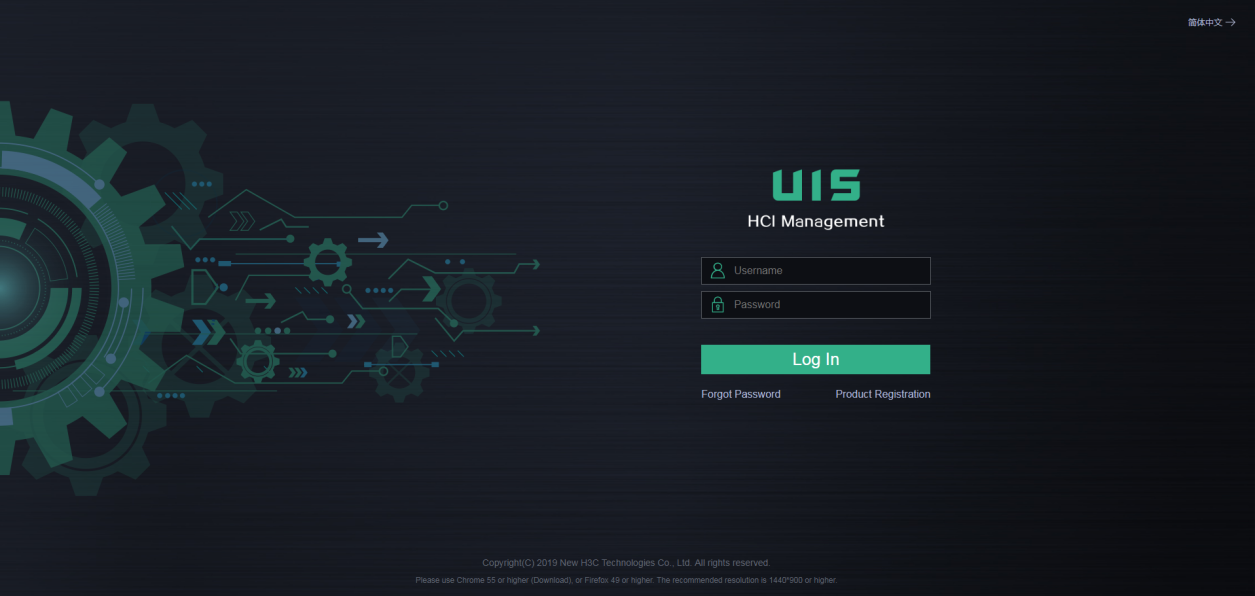
2. Enter your username (admin by default) and password (Cloud@1234 by default) and then click Login.
|
|
NOTE: In a version earlier than UIS-E0715, the default username and password for logging in to UIS Manager are both admin. |
Launching the UIS Setup Wizard
Restrictions and guidelines
You can deploy distributed storage only in an HCI deployment scenario.
If a separate physical interface is not available, different networks can share a physical interface.
Deploying UIS Manager in the compute virtualization scenario
Setting up UIS
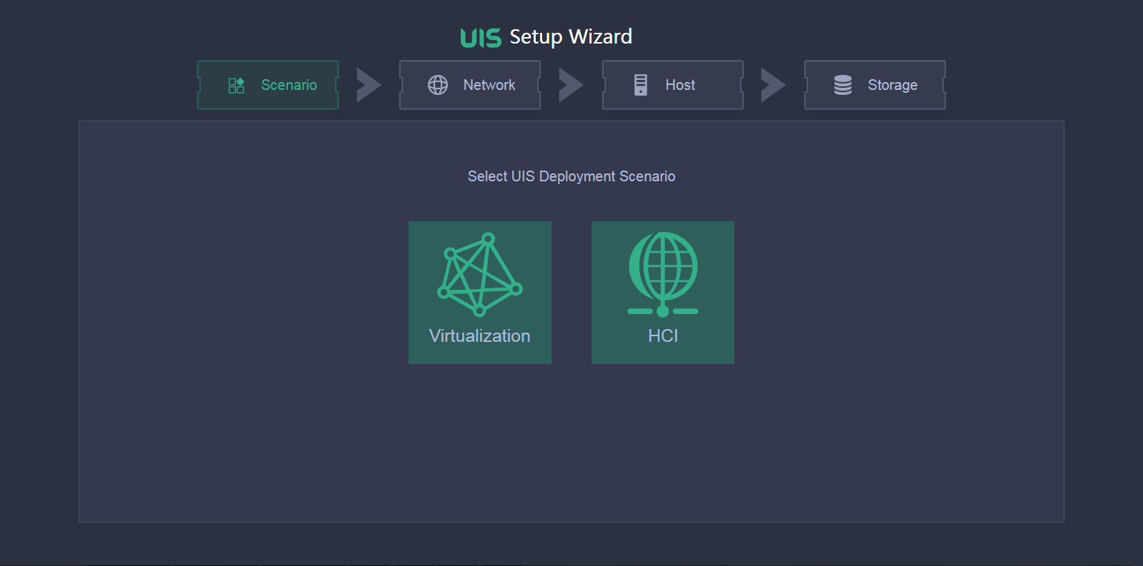
1. Access UIS Manager.
2. On the UIS Setup Wizard page, click Virtualization.
Figure 90 Selecting a scenario

3. Configure network parameters as needed, and then click Next.
Figure 91 Configuring network parameters
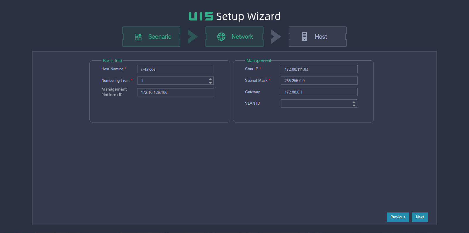
Table 47 Parameter description
|
Item |
Description |
|
Host Naming |
Set the host name prefix. The host name must be a string of a maximum of 255 characters that contains only letters, digits, and hyphens (-). It cannot contain underscores (_) or start with a digit. The host name is automatically configured during the initialization process. After the initialization process finishes, you are not allowed to edit the host name. Plan the host name prefix in advance. |
|
Numbering From |
Specify the start number for host naming. A host name is a number attached to the specified host name prefix. The system assigns the start number to the management node and assigns the next available numbers to the service nodes joining the cluster afterward with an increment of 1. For example, if the host name prefix is cvknode and the start number is 1, the name of the management node is cvknode1 and the names of the service nodes joining the cluster are cvknode2, cvknode3, and cvknode4 in sequence. |
|
Management Platform IP |
The default value is the IP address of the management node. You can change the value as required. |
|
Start IP |
The default value is the start IP address of the management network segment. The system assigns the start IP address to the management network gateway by default. The default start IP and the subnet mask determine the management network segment. The management Platform IP address must be on the management network segment. If you do not manually specify a management IP address for a service node, the system assigns the next available IP address to the service node with an increment of 1. |
|
VLAN ID |
Select a VLAN ID for the management network. You must first configure VLAN settings from the Xconsole of each host. For more information, see "Configuring management interface parameters." |
4. In the dialog box that opens, click OK.
Figure 92 Configuration tip
|
|
NOTE: If the start IP address is different from the management interface IP used for login, the system refreshes the page and opens the Hosts page by using the start IP address. At next login, you must use the start IP address as the management IP address. |
5. Select hosts for the storage cluster.
Figure 93 Selecting hosts for the storage cluster
6. Click the ![]() icon
for a host.
icon
for a host.
7. Configure host parameters as needed.
Figure 94 Customizing configuration for a host
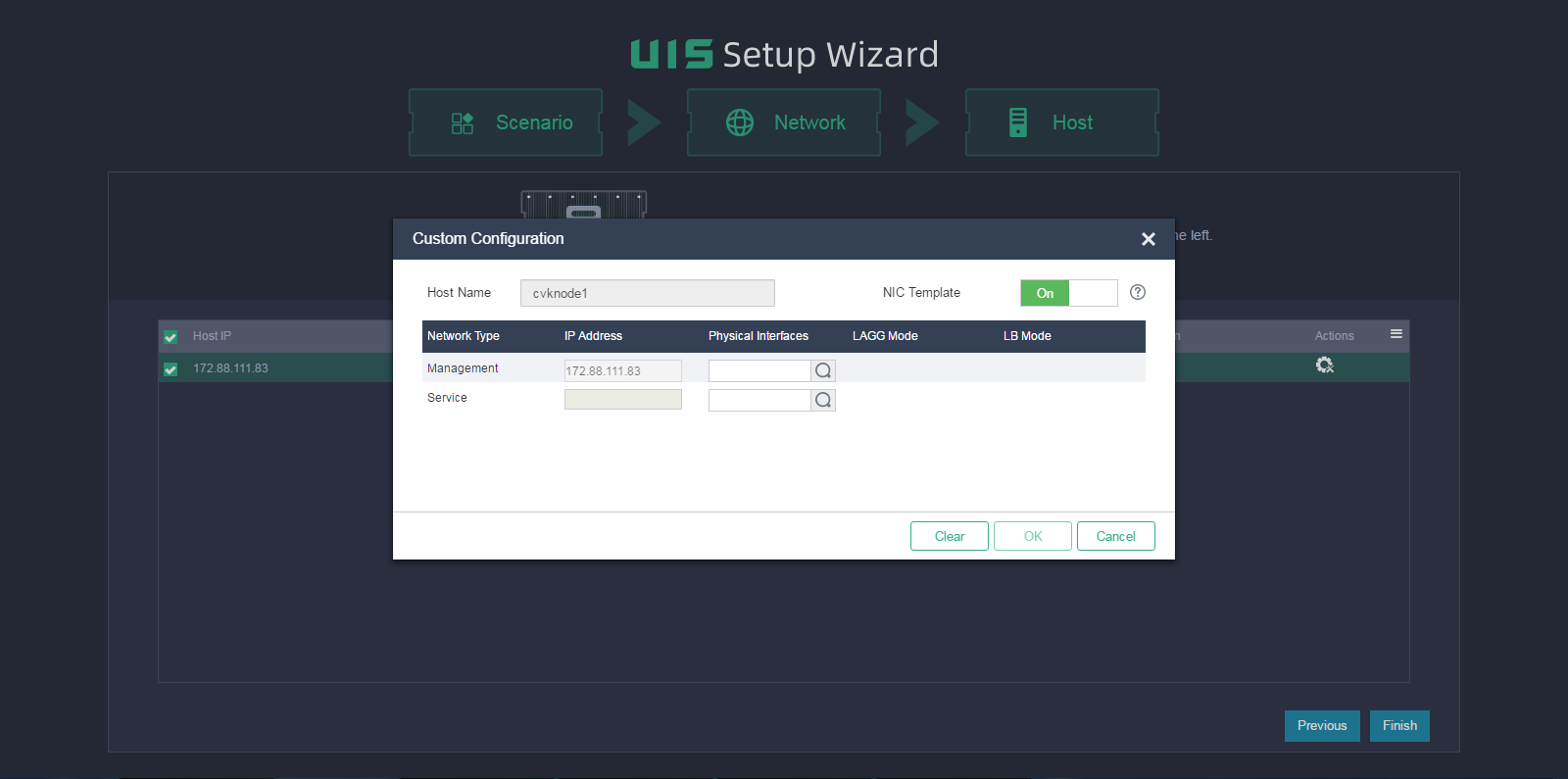
Table 48 Parameter description
|
Item |
Description |
|
Host Name |
Specify a host name for the service node. For the management node, the host name is the start number attached to the specified host name prefix. If you do not specify a host name for a service node, the system automatically creates a name for the node by adding the next available number to the host name prefix. As a best practice, specify a host name that helps node identification. |
|
NIC Template |
Select whether to apply physical interface settings on the host to other hosts. For this feature to take effect, make sure the other hosts have active physical interfaces of the same names as those on this host and the interface speeds are as required. If a host cannot meet the requirements, you must configure physical interface settings for the host manually. |
|
IP Address |
Specify a management IP address for the service node. If you do not specify a management IP address, the system assigns an available IP next to the start IP with an increment of 1 to the host. You do not need to specify a service network IP for a host. |
|
Physical Interfaces |
Specify the physical interfaces for the management network and service network. For the management network, this field is required. To specify an aggregate interface, first configure link aggregation from the Xconsole on each host. For more information, see "Configuring management interface parameters." For the service network, this field is optional. If you do not specify the interface, the system does not create a virtual switch for the service network after deployment, and you must create the switch from UIS Manager manually. |
|
|
IMPORTANT: To avoid configuration lost, make sure the interface sharing settings (except for interface numbers) for all the hosts are the same. For example, in a two-host cluster, the management and service networks for host A use physical interfaces eth0 and eth1, respectively. Whether the interface settings for host A can take effect depends on settings for host B. · If you configure the management and service networks for host B to share one physical interface eth0, the physical interface settings for host A become invalid. · If you configure the management and service networks for host B to use physical interfaces eth2 and eth3, respectively, the physical interface settings for host A are still valid. |
8. Click the ![]() icon
for the management network (required) and service network to specify a physical
interface for them, and then click OK.
icon
for the management network (required) and service network to specify a physical
interface for them, and then click OK.
9. Configure physical interface parameters as needed and then click OK.
The link aggregation mode at the switch side depends on the configured LAGG mode and LB mode. Use Table 50 to determine the link aggregation mode at the switch side.
Figure 95 Selecting physical interfaces

Table 49 Parameter description
|
Item |
Description |
|
LAGG Mode |
Select the aggregation mode of physical NICs in the management network. Options include Static and Dynamic. As a best practice, set the mode to dynamic. The physical switch must be enabled with LACP if the dynamic LAGG mode is used. This parameter is displayed only when multiple physical interfaces are configured for the management network. |
|
LB Mode |
Select the load balancing mode of physical NICs in the management network. Options include Advanced, Basic, and Active/Standby. This parameter is displayed only when multiple physical interfaces are configured for the management network. · Advanced—Load balances physical NICs based on the Ethernet type, IP protocol, source IP address, destination IP address, application layer source port number, and application layer destination port number of packets. · Basic—Load balances physical NICs based on the source MAC address and VLAN tag of packets. · Active/Standby—Load balances the active and standby physical NICs. When the active physical NIC fails, the system switches to the standby physical NIC for traffic forwarding. This option is displayed only when the static LAGG mode is used. As a best practice, use the advanced LB mode in scenarios that require load balancing. |
Table 50 Required link aggregation mode at the switch side
|
Host LAGG mode |
Host LB mode |
Switch link aggregation mode |
|
Static |
Active/standby |
Not configured |
|
Static |
Basic |
Static |
|
Static |
Advanced |
Static |
|
Dynamic |
Basic |
Dynamic |
|
Dynamic |
Advanced |
Dynamic |
|
|
IMPORTANT: If VLAN settings are configured for the logical networks, configure the physical switch ports as trunk ports and assign the ports to the corresponding VLAN. |
10. Click OK.
11. Click Finish.
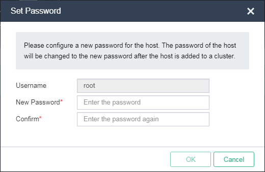
12. Set the root password for all hosts. The password must contain a minimum of eight characters and characters from at least two of the following categories: letters, digits, and special characters.
Figure 96 Setting the root password

13. Click OK.
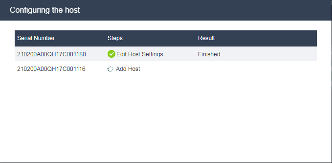
The system starts to configure the host and will open the UIS Manager dashboard after host configuration.
Figure 97 Configuring the host
Adding a virtual switch for the storage network
A virtual switch provides software-based switching between VMs, hosts, and the external network. Perform this task only when IP SAN storage is used.
To add a virtual switch for the storage network:
1. On the top navigation bar, click Networks, and then select vSwitches from the navigation pane.
Figure 98 Accessing the vSwitches list

2. Click Add.
3. Enter the vSwitch name, select Storage as the network type, select VEB as the forwarding mode, and enter the VLAN ID.
Figure 99 Configuring basic vSwitch information
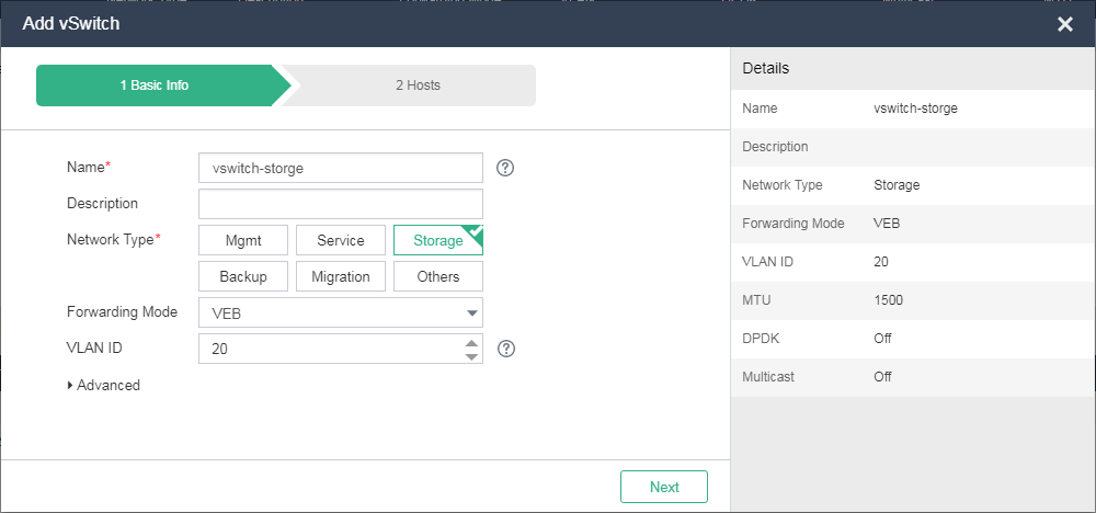
4. Click Next.
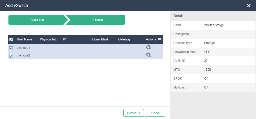
5. Select the hosts on which you want to create a virtual switch.
Figure 100 Configuring host information
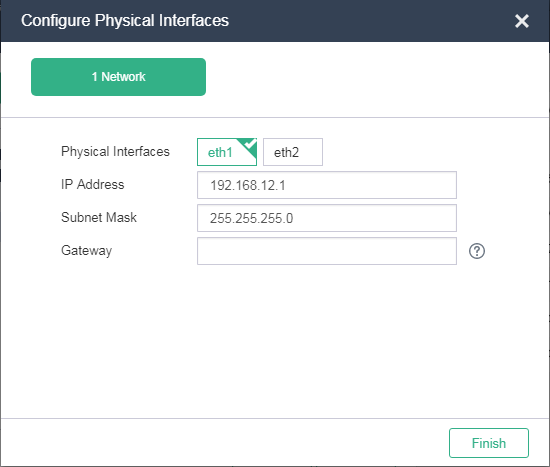
6. Click the ![]() icon
for each host to configure physical interface information. On the window that
opens, select one physical interface or two physical interfaces to form an
aggregate interface, enter IP address and subnet mask, and then click Finish.
icon
for each host to configure physical interface information. On the window that
opens, select one physical interface or two physical interfaces to form an
aggregate interface, enter IP address and subnet mask, and then click Finish.
Figure 101 Configuring physical interfaces
7. Click Finish when the page as shown in Figure 100 appears.
Configuring network-shared storage
Make sure the storage device is reachable from the host.
To configure network-shared IP SAN storage, start from step 1. To configure network-shared FC SAN storage, start from step 4.
To configure network shared storage:
1. On the top navigation bar, click Hosts, and then select a host from the navigation pane.
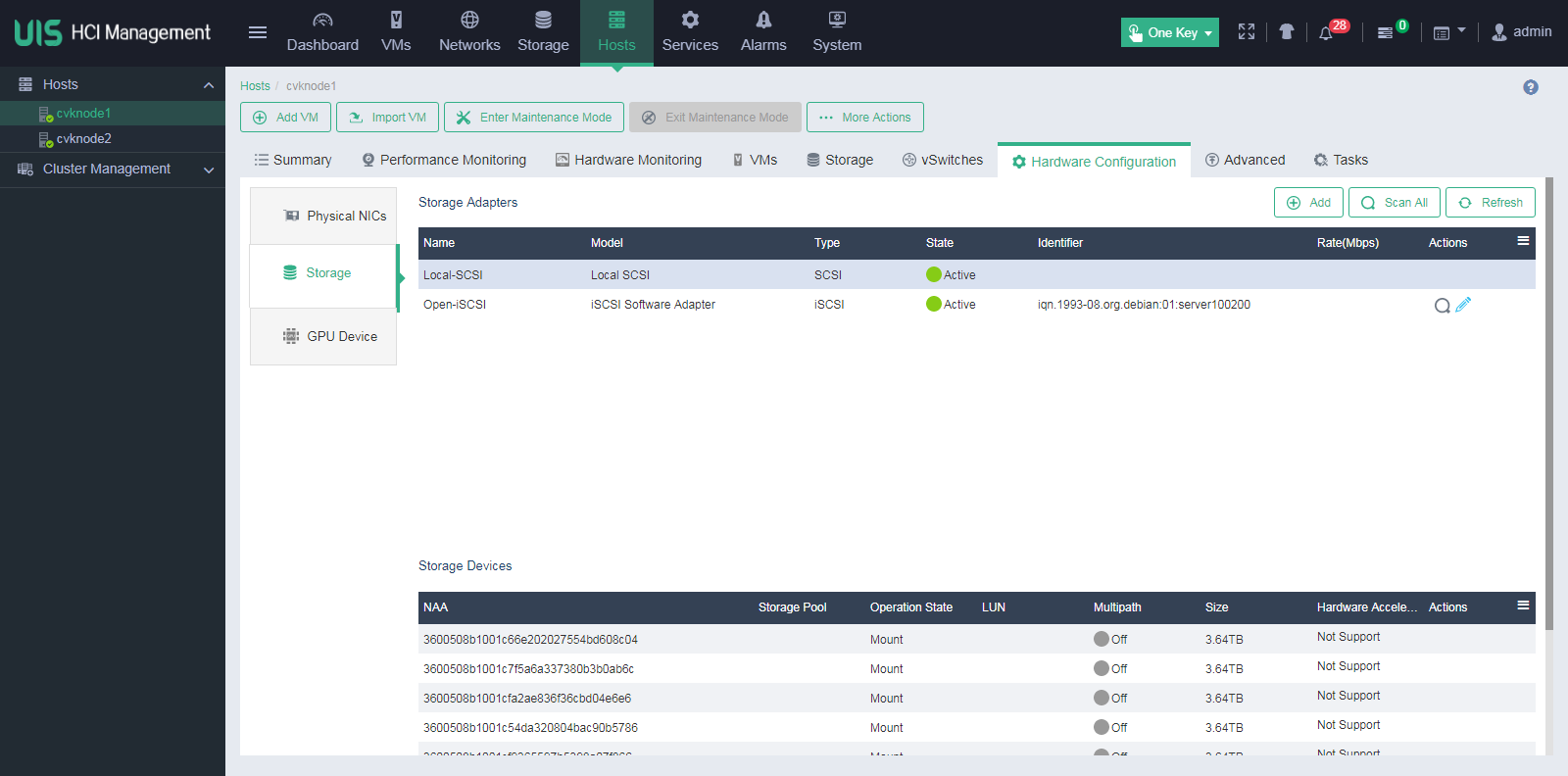
2. Click the Hardware Configuration tab and then
select Storage to view the IQN for the host. To change the IQN, click the Edit icon ![]() .
.
Figure 102 Obtaining the host IQN
3. Configure network-shared storage settings on the iSCSI storage device, including host, LUN, and LUN-host mapping settings.
4. In UIS Manager, click Storage on the top navigation bar, and select Shared Storage from the navigation pane.
Figure 103 Configuring shared storage

5. Click Add.
6. Configure basic information as needed.
Figure 104 Configuring basic shared storage information

Table 51 Parameter description
|
Item |
Description |
|
Type |
To access an IP SAN storage device, select iSCSI Shared Directory. To access an FC SAN storage device, select FC Shared Directory. |
|
Target Path |
The point to mount the shared file system in the client. The target path is created by the system automatically and cannot be edited. |
7. Click Next.
8. Configure LUN information as needed.
Figure 105 Configuring LUN information

Table 52 Parameter description
|
Item |
Description |
|
IP Address |
Specify the IP address of the IP SAN storage server. This field is required for an iSCSI shared directory. If multiple paths are available, use semicolons (;) to separate the IP addresses. |
|
LUN |
Specify a LUN for the shared file system. This field is required for an iSCSI shared directory. |
|
NAA |
Specify the network addressing authority identifier for the LUN, which is a unique identifier of the LUN on the storage server. For an iSCSI shared directory, this field is automatically determined by the selected LUN. For an FC shared directory, you must select a LUN for this field. |
|
Service Storage |
Enable this option to allow the shared file system to be used for storing files of the VMs automatically deployed by the system. |
9. Click Next.
10. Select hosts that can act as clients to access the shared storage, and then click Finish.
11. In the confirmation dialog box that opens, click OK.
Figure 106 Confirming the shared storage adding operation
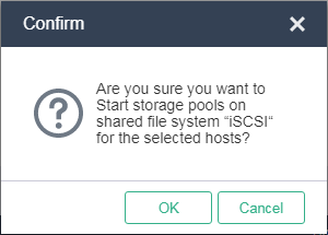
12. In the dialog box that opens, click OK to format the shared file system.
Figure 107 Formatting the shared file system

After shared storage configuration, you can create VMs in UIS Manager.
Deploying UIS Manager in the HCI scenario
1. Access UIS Manager, and click HCI on the UIS Setup Wizard page.
Figure 108 Selecting a scenario
2. Configure network parameters and then click Next.
Figure 109 Configuring network parameters

Table 53 Parameter description
|
Item |
Description |
|
Host Naming |
Set the host name prefix. The host name must be a string of a maximum of 255 characters that contains only letters, digits, and hyphens (-). It cannot contain underscores (_) or start with a digit. The host name is automatically configured during the initialization process. After the initialization process finishes, you are not allowed to edit the host name. Plan the host name prefix in advance. |
|
Numbering From |
Specify the start number for host naming. A host name is a number attached to the specified host name prefix. The system assigns the start number to the management node and assigns the next available numbers to the service nodes joining the cluster afterward with an increment of 1. For example, if the host name prefix is cvknode and the start number is 1, the name of the management node is cvknode1, and the names of the three service nodes joining the cluster are cvknode2, cvknode3, and cvknode4 in sequence. |
|
Management Platform IP |
The default value is the IP address of the management node. You can change the value as required. |
|
Start IP |
Specify the start IP address for the network. · Management network—The default value is the start IP address of the management network segment. The system assigns the start IP address to the management network gateway by default. The default start IP and the subnet mask determine the management network segment. The management IP address must be on the management network segment. By default, the system assigns the next available IP address starting from the start IP to the service nodes joining the cluster in sequence with an increment of 1. You can also specify a management network IP address for a service node manually. · Storage front-end and storage back-end networks—The IP addresses are used for internal access. Use the default settings unless otherwise specified. |
|
VLAN ID |
Select a VLAN ID for the network. For the management network, you must first configure VLAN settings from the Xconsole of each host. For more information, see "Configuring management interface parameters." |
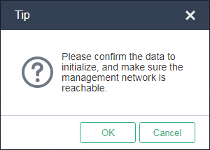
3. In the dialog box that opens, click OK.
Figure 110 Configuration tip

|
|
NOTE: If the start IP address is different from the management interface IP used for login, the system refreshes the page and opens the Hosts page by using the start IP address. At next login, you must use the start IP address as the management IP address. |
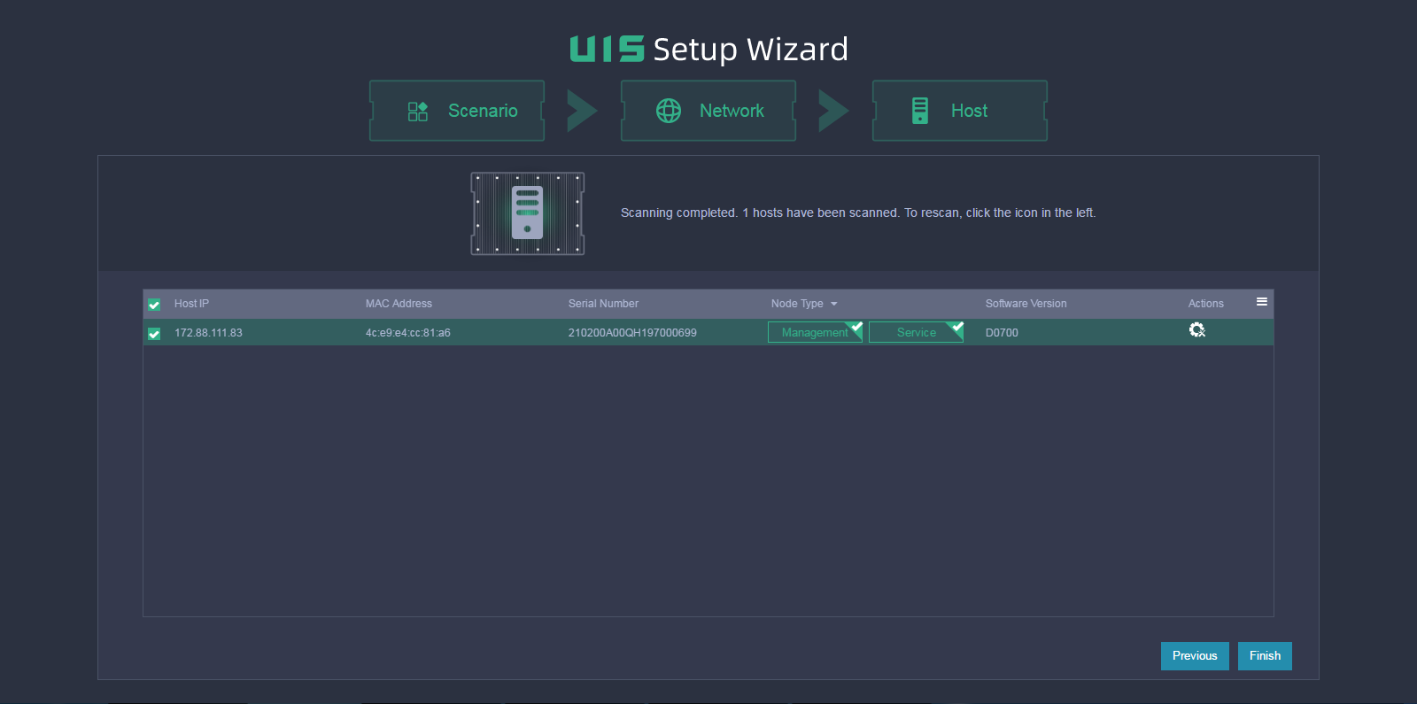
4. Select hosts for the storage cluster.
Figure 111 Selecting hosts for the storage cluster
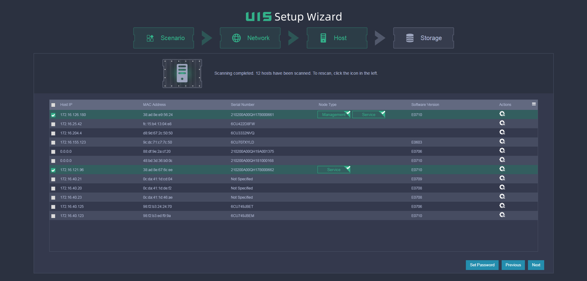
This figure shows the configuration for the converged deployment mode. For separate deployment mode, deselect the Service node type for the management host.
|
|
NOTE: The system adds hosts to the cluster in the order they are selected. |
5. Click the ![]() icon
for a host.
icon
for a host.
6. Configure host parameters as needed.
Figure 112 Customizing configuration for a host
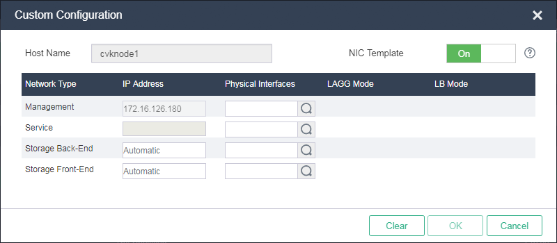
Table 54 Parameter description
|
Item |
Description |
|
Host Name |
Specify a host name for the service node. For the management node, the host name is the start number attached to the specified host name prefix. If you do not specify a host name for a service node, the system automatically creates a name for the node by adding the next available number to the host name prefix. As a best practice, specify a host name that helps node identification. |
|
NIC Template |
Select whether to apply physical interface settings of the host to other hosts. For this feature to take effect, make sure the other hosts have active physical interfaces of the same names as those on this host and the interface speeds are as required. If a host cannot meet the requirements, you must configure physical interface settings for the host manually. |
|
IP Address |
Specify a management IP address for the service node. If you do not specify a management IP address, the system assigns an available IP next to the start IP with an increment of 1 to the host. You do not need to specify a service network IP for a host. |
|
Physical Interfaces |
Specify the physical interfaces for the management network and service network. For the service network, this field is optional. If you do not specify the interface, the system does not create a virtual switch for the service network after deployment, and you must create the virtual switch manually. |
|
|
IMPORTANT: To avoid configuration lost, make sure the interface sharing settings (except for interface numbers) for all the hosts are the same. For example, in a two-host cluster, the management and service networks for host A use physical interfaces eth0 and eth1, respectively, and the storage front-end and back-end networks share physical interfaces eth2 and eth3. Whether the interface settings for host A can take effect depends on settings for host B. · If you configure the storage front-end and back-end networks to share interfaces eth1 and eth2, and the management and service networks to share interface eth0, the physical interface settings for host A become invalid. · If you configure the management and service networks to use interfaces eth0 and eth1, respectively, and the storage front-end and back-end networks to share interfaces eth3 and eth4, the physical interface settings for host A are still valid. |
7. Click the ![]() icon
for a management network, service network (optional), storage back-end network,
and storage front-end network to specify a physical interface for them, and then
click OK.
icon
for a management network, service network (optional), storage back-end network,
and storage front-end network to specify a physical interface for them, and then
click OK.
8. Configure physical interface parameters as needed and then click OK.
The link aggregation mode at the switch side depends on the configured LAGG mode and LB mode. Use Table 56 to determine the link aggregation mode at the switch side.
Figure 113 Selecting physical interfaces

Table 55 Parameter description
|
Item |
Parameters |
|
LAGG Mode |
Select the aggregation mode of physical NICs in the management network. Options include Static and Dynamic. The physical switch must be enabled with LACP if the dynamic LAGG mode is used. This parameter is displayed only when multiple physical interfaces are configured for the management network. As a best practice, set the LAGG mode to dynamic. |
|
LB Mode |
Select the load balancing mode of physical NICs in the management network. Options include Advanced, Basic, and Active/Standby. This parameter is displayed only when multiple physical interfaces are configured for the management network. · Advanced—Load balances physical NICs based on the Ethernet type, IP protocol, source IP address, destination IP address, application layer source port number, and application layer destination port number of packets. · Basic—Load balances physical NICs based on the source MAC address and VLAN tag of packets. · Active/Standby—Load balances the active and standby physical NICs. When the active physical NIC fails, the system switches to the standby physical NIC for traffic forwarding. This option is displayed only when the static LAGG mode is used. As a best practice, use the advanced LB mode in scenarios that require load balancing. |
Table 56 Required link aggregation mode at the switch side
|
Host LAGG mode |
Host LB mode |
Switch link aggregation mode |
|
Static |
Active/standby |
Not configured |
|
Static |
Basic |
Static |
|
Static |
Advanced |
Static |
|
Dynamic |
Basic |
Dynamic |
|
Dynamic |
Advanced |
Dynamic |
|
|
IMPORTANT: If VLAN settings are configured for the logical networks, configure the physical switch ports as trunk ports and assign the ports to the corresponding VLAN. |
9. Click OK.
10. Click Set Password on the Host page as shown in Figure 111.
11. Set the root password for all hosts and then click OK. The password must contain a minimum of eight characters and characters from at least two of the following categories: letters, digits, and special characters.
Figure 114 Setting the root password
12. Click Next on the Host page as shown in Figure 111 and then verify the host settings.
Figure 115 Verifying host settings

13. Click OK.
The system starts to configure the host.
|
|
IMPORTANT: If a host fails to be configured, its default host name and network settings will be restored. To reconfigure the host, you must first restart the host and verify network configurations. |
Figure 116 Configuring the host

14. Configure storage deployment parameters as needed. The parameter settings vary by the storage service type you select. The available storage service types include Block Storage, File Storage, and Object Storage.
¡ If you select the Block Storage service type, configure the parameters as described in Table 34.
Figure 117 Configuring block storage

Table 57 Parameter description
|
Item |
Description |
|
Deployment Mode |
Select the block storage deployment mode. Options include SSD caches+HDDs, All SSDs, All HDDs, and HDDs+SSDs. For more information, see "Planning deployment modes." |
|
Provisioning |
Select a block device provisioning mode. After UIS setup, the system creates a disk pool with the specified block device provisioning mode. This parameter determines how space is allocated to the block devices created in a disk pool and whether resource overcommitment is allowed. · Thick—Allocates the specified maximum storage space to a block device when the block device is created. The capacity of a block device in a disk pool cannot exceed the available capacity of the disk pool. · Thin—Allocates space to a block device on demand. The capacity assigned to a block device when it is created can exceed the available capacity of the disk pool. |
|
Replicas |
Set the number of replicas. After UIS setup, the system creates a block device with the specified number of replicas. The maximum capacity of the block device is 40% of the total available capacity of the storage cluster or 16 TB (if the 40% total available capacity exceeds 16 TB). |
|
Cache Size |
Set the cache size. This parameter is available only when you select the SSD caches+HDDs deployment mode. The system divides SSDs into partitions and assigns a partition to each HDD data disk as its cache. You can set a cache size from 50 GB to 200 GB. A cache of a larger size has better performance. Make sure the cache sizes assigned to HDDs are fewer than the total size of the SSD caches. The cache sizes cannot be edited after configuration. Reserve sufficient cache size for possible HDD expansion in the future. For more information, see "Planning storage." |
|
Cache Protection Level |
Select a cache protection level. This parameter is configurable when the deployment mode is SSD Caches+HDDs. · Standard—Cache and metadata are stored in cache disks in RAID0 mode. · Advanced—Cache and metadata are stored in cache disks in RAID1 mode. In the current software version, only some device models (such as R4900 G3) support the advanced level. For more information, see the compatibility matrixes. |
|
Fault Domain |
Select a fault domain level for the storage cluster. By using fault domains and a redundancy policy together, a storage cluster saves the replicas or fragments of data to different fault domains to ensure data security and high availability. The system supports the rack level and host level. For more information, see "Planning fault domains." |
¡ If you select the File Storage service type, configure the parameters as described in Table 58.
Figure 118 Configuring file storage
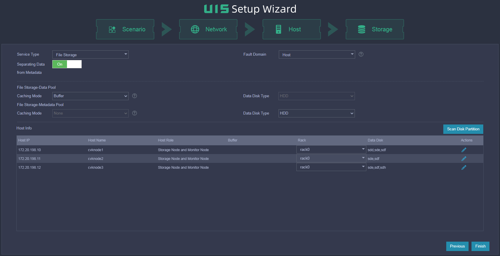
Table 58 Parameter description
|
Item |
Description |
|
Separating Data from Metadata |
Select whether to separate data from metadata. · Yes—Data and metadata are saved separately in two disk pools. Use this mode to provide high performance. If you select this mode, the system creates disk pools of the Object Storage-Data Pool type and Object Storage-Metadata Pool type automatically after initialization. · No—Data and metadata are saved in one disk pool. Use this mode in scenarios with limited storage resources. If you select this mode, the system creates a disk pool of the Object Storage type automatically after initialization. |
|
Fault Domain |
Select a fault domain level for the storage cluster. By using fault domains and a redundancy policy together, a storage cluster saves the replicas or fragments of data to different fault domains to ensure data security and high availability. The system supports the rack level and host level. For more information, see "Planning fault domains." |
|
Caching Mode |
Select the caching mode for the disk pool automatically created by the system. Options include None and Buffer. If you select the Buffer caching mode, you can create data disks and cache disks from the disk pool and use cache disks as the cache pool of the file storage data pool to accelerate data read and write. |
|
Data Disk Type |
Select the type of disks for storing data. Only disks of the specified type can be added to the disk pool. |
¡ If you select the Object Storage service type, configure the parameters as described in Table 59.
Figure 119 Configuring object storage

Table 59 Parameter description
|
Item |
Description |
|
Separating Data from Metadata |
Select whether to separate data from metadata. · Yes—Data and metadata are saved separately in two disk pools. Use this mode to provide high performance. If you select this mode, the system creates disk pools of the Object Storage-Data Pool type and Object Storage-Metadata Pool type automatically after initialization. · No—Data and metadata are saved in one disk pool. Use this mode in scenarios with limited storage resources. If you select this mode, the system creates a disk pool of the Object Storage type automatically after initialization. |
|
Fault Domain |
Select a fault domain level for the storage cluster. By using fault domains and a redundancy policy together, a storage cluster saves the replicas or fragments of data to different fault domains to ensure data security and high availability. The system supports the rack level and host level. For more information, see "Planning fault domains." |
|
Deployment Mode |
Select the deployment mode for the disk pools automatically created by the system. Options include SSD caches+HDDs, All SSDs, All HDDs, and HDDs+SSDs. For more information, see "Planning deployment modes." |
|
Cache Size |
Set the cache size. This parameter is available only when you select the SSD caches+HDDs deployment mode. The system divides SSDs into partitions and assigns a partition to each HDD data disk as its cache. You can set a cache size to a value from 50 GB to 200 GB. A cache of a larger size has better performance. Make sure the sum of cache sizes assigned to HDDs is less than the total size of the SSD caches. The cache sizes cannot be edited after configuration. Reserve sufficient cache size for possible HDD expansion in the future. For more information, see "Planning storage." |
|
Cache Protection Level |
Select a cache protection level. This parameter is configurable when the deployment mode is SSD Caches+HDDs. · Standard—Cache and metadata are stored in cache disks in RAID0 mode. · Advanced—Cache and metadata are stored in cache disks in RAID1 mode. In the current software version, only some device models (such as R4900 G3) support the advanced level. For more information, see the compatibility matrixes. |
15. (Optional.) Clear partitions on disks. Only non-partitioned disks can be deployed as cache disks or data disks. When a disk already has partitions, you can clear the partitions on it as needed.
Click Scan Disk Partition. On the dialog box that opens, you can view disks with partitions on all hosts in the cluster. To clear the disks with partitions, select the hosts and disks and then click Clear Disk Partition.
16. Select a rack for each host.
a. Select Configure rack from the Rack list. On the dialog box that opens, click Add rack.
b. Set the rack name and quantity and then click OK.
c. Select a rack and then click OK.
Figure 120 Configuring racks
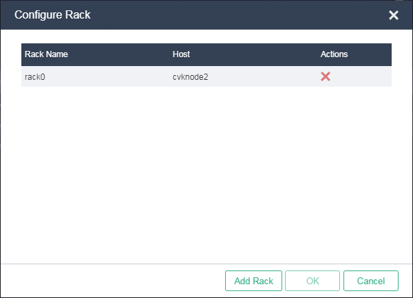
Figure 121 Adding racks
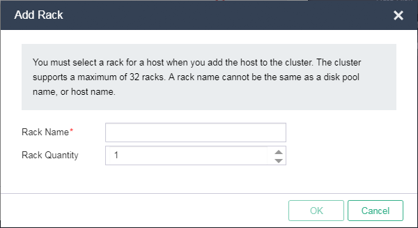
|
|
IMPORTANT: · A storage cluster can have a maximum of 32 racks. · A rack name cannot be identical to a disk pool name or host name. · As a best practice, create racks based on the actual rack mounting conditions of the hosts. For example, if six physical hosts are mounted on two racks, you can use the actual rack names to create two racks. |
17. Click the ![]() icon
in the Actions column for the host. On the dialog box that opens, edit the host
information.
icon
in the Actions column for the host. On the dialog box that opens, edit the host
information.
Figure 122 Editing host information
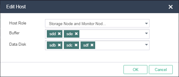
|
|
IMPORTANT: You must specify a minimum of two data disks for each node in HIC deployment on three or more hosts. |
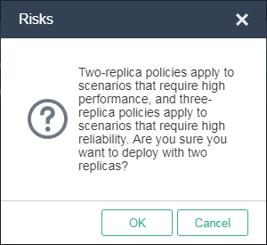
18. Click Finish.
19. In the Risks dialog box that opens, click OK.
Figure 123 Risk prompt
20. In the Confirm dialog box that opens, click OK.
Figure 124 Operation confirming

The system starts to deploy distributed storage and will open the UIS Manager dashboard after deployment. Then, you can create VMs in UIS Manager.
Figure 125 Deploying distributed storage
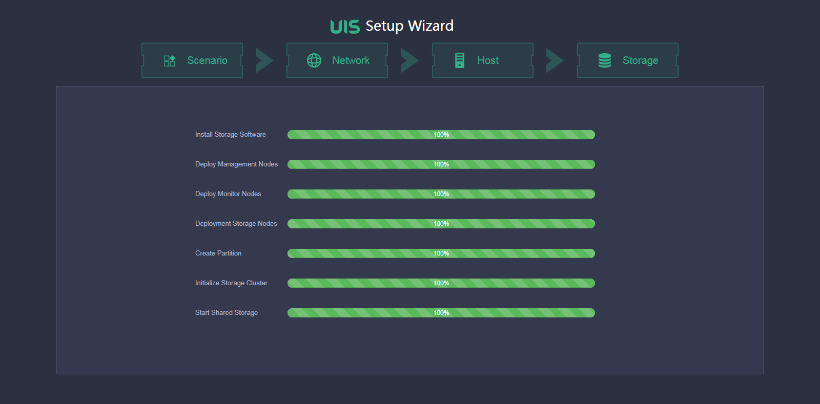
Figure 126 UIS Manager dashboard
Specifying NTP servers
1. Log in to UIS Manager.
2. Click System from the top navigation bar and select NTP Server from the navigation pane.
Figure 127 Setting the NTP server

3. Specify a primary NTP server and a secondary NTP server as needed.
By default, the management node acts as the primary NTP server and the secondary NTP server is not specified.
4. Click Save.
Configuring stateful failover
For information about configuring a UIS Manager stateful failover system, see H3C UIS Manager Stateful Failover Configuration Guide.
Registering licenses
For information about registering licenses for UIS Manager, see H3C UIS Manager License Registration Guide.
FAQ
Which browsers can I use to access UIS Manager?
You can access UIS Manager through most mainstream browsers, including Google Chrome with version 45 or higher and Mozilla Firefox with version 49 or higher.
Do I need to install a client on a PC to access UIS Manager?
No. UIS Manager uses a standard B/S architecture and allows for access from a browser at http://manage_node_management_IP:8080 or https://manage_node_management_IP:8443.
manage_node_management_IP represents the management interface IP address of the management node.
Why does the page display effect vary by browser type?
Different browsers might display webpages in different ways, but this will not affect UIS Manager's functions.
Which method is better for UIS Manager installation, USB disk or virtual drive?
As a best practice, use a USB disk to install UIS Manager.
How do I configure the port that connects a physical switch to a physical interface on a host based on the LAGG mode and LB mode configured for the host?
The settings for the management network, service network, storage back-end network port, and storage front-end network are the same. The following uses the management network as an example.
· Do not configure link aggregation on the port if the LAGG mode is Static and the LB mode is Active/Standby.
· Configure static link aggregation on the port if the LAGG mode is Static and the LB mode is Advanced or Basic. If UIS Manager cannot detect the host after the configuration, shut down all the physical switch ports connecting to the host's management network ports that are not bound to vswitch0. Then, try to detect the host again.
· Configure dynamic link aggregation on the port if the LAGG mode is Dynamic. If UIS Manager cannot detect the host after the configuration, specify the physical switch ports that connecting to the host's management network ports as edge aggregate interfaces. Then, try to detect the host again.
