- Table of Contents
-
- 07-MPLS Configuration Guide
- 00-Preface
- 01-Basic MPLS configuration
- 02-Static LSP configuration
- 03-LDP configuration
- 04-MPLS TE configuration
- 05-Static CRLSP configuration
- 06-RSVP configuration
- 07-Tunnel policy configuration
- 08-MPLS L3VPN configuration
- 09-MPLS L2VPN configuration
- 10-VPLS configuration
- 11-MPLS OAM configuration
- 12-MCE configuration
- 13-Static SR over MPLS configuration
- Related Documents
-
| Title | Size | Download |
|---|---|---|
| 02-Static LSP configuration | 78.08 KB |
Configuration restrictions and guidelines
Hardware resource restrictions
Static LSP configuration example
Configuration restrictions and guidelines
Configuring a static LSP
Overview
A static label switched path (LSP) is established by manually specifying the incoming label and outgoing label on each node (ingress, transit, or egress node) of the forwarding path.
Static LSPs consume fewer resources, but they cannot automatically adapt to network topology changes. Therefore, static LSPs are suitable for small and stable networks with simple topologies.
The ingress node of a static LSP performs the following operations:
1. Determines an FEC for a packet according to the destination address.
2. Adds the label for that FEC into the packet.
3. Forwards the packet to the next hop or out of the outgoing interface.
A transit node swaps the label carried in a received packet with a label, and forwards the packet to the next hop or out of the outgoing interface.
If PHP is not configured, an egress node pops the incoming label of a packet, and performs label forwarding according to the inner label or IP forwarding.
Configuration restrictions and guidelines
Hardware resource restrictions
MPLS shares hardware resources with VXLAN when the VXLAN hardware resource mode is the Layer 2 gateway mode on the following devices:
· S6800-2C-FC switches.
· S6800-54HF switches.
· S6800-54HT switches.
· Switches labeled with the following product codes:
¡ LS-6800-2C-H1.
¡ LS-6800-32Q-H1.
¡ LS-6800-4C-H1.
¡ LS-6800-54QF-H1.
¡ LS-6800-54QF-H3.
¡ LS-6800-54QT-H1.
¡ LS-6800-54QT-H3.
To configure static LSP on these devices, you must set the VXLAN hardware resource mode to Layer 2 gateway mode. In any other mode than Layer 2 gateway mode, MPLS features are not available because no hardware resources can be used for MPLS. For more information about VXLAN hardware resource modes, see VXLAN Configuration Guide.
Configuration guidelines
Follow these guidelines when you establish a static LSP:
· On the ingress node, you must specify the outgoing label for the destination address (the FEC) and the next hop or the outgoing interface.
· On each transit node, you must specify the incoming label, the outgoing label, and the next hop or the outgoing interface.
· On the egress node, you must specify the incoming label.
· You can associate a static LSP with an LDP LSP to simplify packet processing when the following conditions are met:
¡ Packets are forwarded over the static LSP and the LDP LSP to the destination.
¡ The egress node of the static LSP is also the ingress node of the LDP LSP.
After receiving a packet with the specified incoming label, the egress node of the static LSP swaps the label with the outgoing label for the LDP LSP. Then, the node forwards the packet to the next hop.
To associate a static LSP with an LDP LSP, specify the incoming label and destination address on the egress node of the static LSP.
· The outgoing label specified on an LSR must be the same as the incoming label specified on the directly connected downstream LSR.
Configuration prerequisites
Before you configure a static LSP, perform the following tasks:
· Identify the ingress node, transit nodes, and egress node of the LSP.
· Enable MPLS on all interfaces that participate in MPLS forwarding. For more information, see "Configuring basic MPLS."
· Make sure the ingress node has a route to the destination address of the LSP.
· If you want to associate the static LSP with an LDP LSP, make sure the egress node of the static LSP has a route to the destination.
Configuration procedure
To configure a static LSP:
|
Step |
Command |
Remarks |
|
1. Enter system view. |
system-view |
N/A |
|
2. Configure the ingress node of the static LSP. |
static-lsp ingress lsp-name destination ip-address { mask | mask-length } { nexthop next-hop-ip-address | outgoing-interface interface-type interface-number } out-label out-label |
If you specify a next hop for the static LSP, make sure the ingress node has an active route to the specified next hop address. |
|
3. Configure the transit node of the static LSP. |
static-lsp transit lsp-name in-label in-label { nexthop next-hop-ip-address | outgoing-interface interface-type interface-number } out-label out-label |
If you specify a next hop for the static LSP, make sure the transit node has an active route to the specified next hop address. |
|
4. Configure the egress node of the static LSP. |
static-lsp egress lsp-name in-label in-label [ destination ip-address { mask | mask-length } ] |
You do not need to configure this command if the outgoing label configured on the penultimate hop of the static LSP is 0 or 3. |
Displaying static LSPs
Execute display commands in any view.
|
Task |
Command |
|
Display static LSP information. |
display mpls static-lsp [ lsp-name lsp-name ] |
Static LSP configuration example
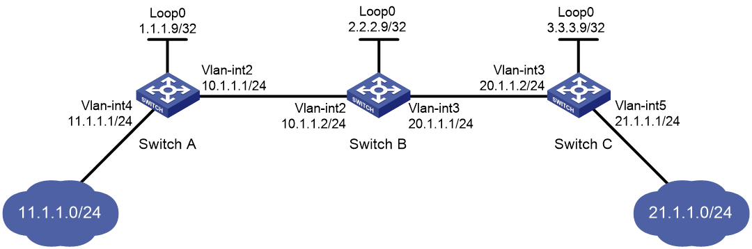
Network requirements
Switch A, Switch B, and Switch C all support MPLS.
Establish static LSPs between Switch A and Switch C, so that subnets 11.1.1.0/24 and 21.1.1.0/24 can access each other over MPLS.
Configuration restrictions and guidelines
· For an LSP, the outgoing label specified on an LSR must be identical with the incoming label specified on the downstream LSR.
· LSPs are unidirectional. You must configure an LSP for each direction of the data forwarding path.
· A route to the destination address of the LSP must be available on the ingress and egress nodes, but it is not needed on transit nodes. Therefore, you do not need to configure a routing protocol to ensure IP connectivity among all switches.
Configuration procedure
1. Create VLANs and configure IP addresses for all interfaces, including the loopback interfaces, as shown in Figure 1. (Details not shown.)
2. Configure a static route to the destination address of each LSP:
# On Switch A, configure a static route to network 21.1.1.0/24.
<SwitchA> system-view
[SwitchA] ip route-static 21.1.1.0 24 10.1.1.2
# On Switch C, configure a static route to network 11.1.1.0/24.
<SwitchC> system-view
[SwitchC] ip route-static 11.1.1.0 255.255.255.0 20.1.1.1
3. Configure basic MPLS on the switches:
# Configure Switch A.
[SwitchA] mpls lsr-id 1.1.1.9
[SwitchA] interface vlan-interface 2
[SwitchA-Vlan-interface2] mpls enable
[SwitchA-Vlan-interface2] quit
# Configure Switch B.
[SwitchB] mpls lsr-id 2.2.2.9
[SwitchB] interface vlan-interface 2
[SwitchB-Vlan-interface2] mpls enable
[SwitchB-Vlan-interface2] quit
[SwitchB] interface vlan-interface 3
[SwitchB-Vlan-interface3] mpls enable
[SwitchB-Vlan-interface3] quit
# Configure Switch C.
[SwitchC] mpls lsr-id 3.3.3.9
[SwitchC] interface vlan-interface 3
[SwitchC-Vlan-interface3] mpls enable
[SwitchC-Vlan-interface3] quit
4. Configure a static LSP from Switch A to Switch C:
# Configure the LSP ingress node, Switch A.
[SwitchA] static-lsp ingress AtoC destination 21.1.1.0 24 nexthop 10.1.1.2 out-label 30
# Configure the LSP transit node, Switch B.
[SwitchB] static-lsp transit AtoC in-label 30 nexthop 20.1.1.2 out-label 50
# Configure the LSP egress node, Switch C.
[SwitchC] static-lsp egress AtoC in-label 50
5. Configure a static LSP from Switch C to Switch A:
# Configure the LSP ingress node, Switch C.
[SwitchC] static-lsp ingress CtoA destination 11.1.1.0 24 nexthop 20.1.1.1 out-label 40
# Configure the LSP transit node, Switch B.
[SwitchB] static-lsp transit CtoA in-label 40 nexthop 10.1.1.1 out-label 70
# Configure the LSP egress node, Switch A.
[SwitchA] static-lsp egress CtoA in-label 70
Verifying the configuration
# Display static LSP information on switches, for example, on Switch A.
[SwitchA] display mpls static-lsp
Total: 2
Name FEC In/Out Label Nexthop/Out Interface State
AtoC 21.1.1.0/24 NULL/30 10.1.1.2 Up
CtoA -/- 70/NULL - Up
# Test the connectivity of the LSP from Switch A to Switch C.
[SwitchA] ping mpls -a 11.1.1.1 ipv4 21.1.1.0 24
MPLS ping FEC 21.1.1.0/24 with 100 bytes of data:
100 bytes from 20.1.1.2: Sequence=1 time=4 ms
100 bytes from 20.1.1.2: Sequence=2 time=1 ms
100 bytes from 20.1.1.2: Sequence=3 time=1 ms
100 bytes from 20.1.1.2: Sequence=4 time=1 ms
100 bytes from 20.1.1.2: Sequence=5 time=1 ms
--- Ping statistics for FEC 21.1.1.0/24 ---
5 packets transmitted, 5 packets received, 0.0% packet loss
Round-trip min/avg/max = 1/1/4 ms
# Test the connectivity of the LSP from Switch C to Switch A.
[SwitchC] ping mpls -a 21.1.1.1 ipv4 11.1.1.0 24
MPLS ping FEC 11.1.1.0/24 with 100 bytes of data:
100 bytes from 10.1.1.1: Sequence=1 time=5 ms
100 bytes from 10.1.1.1: Sequence=2 time=1 ms
100 bytes from 10.1.1.1: Sequence=3 time=1 ms
100 bytes from 10.1.1.1: Sequence=4 time=1 ms
100 bytes from 10.1.1.1: Sequence=5 time=1 ms
--- Ping statistics for FEC 11.1.1.0/24 ---
5 packets transmitted, 5 packets received, 0.0% packet loss
Round-trip min/avg/max = 1/1/5 ms