- Table of Contents
-
- H3C S7500X Switch Series Installation Guide-6W105
- 00-Preface
- 01-Chapter 1 Preparing for Installation
- 02-Chapter 2 Installing the Switch
- 03-Chapter 3 Installing FRUs
- 04-Chapter 4 Connecting Your Switch to the Network
- 05-Chapter 5 Replacement Procedures
- 06-Appendix A Chassis Views and Technical Specifications
- 07-Appendix B FRUs and Compatibility Matrixes
- 08-Appendix C LEDs
- 09-Appendix D Cables
- 10-Appendix E Engineering Labels for Cables
- 11-Appendix F Cable Management
- Related Documents
-
| Title | Size | Download |
|---|---|---|
| 08-Appendix C LEDs | 568.30 KB |
8 Appendix C LEDs
The MPUs, service modules, and power modules available for the switch use multiple LEDs to indicate their operating status. The LED type and quantity vary by module model.
Table 8-1 lists the LEDs on the MPUs, service modules, and power modules.
|
|
NOTE: Unless otherwise specified, the flashing frequency of the LEDs in this section is 0.5 Hz. |
|
LEDs |
|
· PSR320-A · PSR650-A/PSR650-D/PSR1200-A/PSR1200-D · PSR650C-12A/PSR650C-12D/PSR1400-A/PSR2500-12AHD/PSR2500-12D |
MPU LEDs
Multiple MPUs are available for the device. These MPUs provide different types and numbers of LEDs.
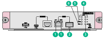
Figure 8-1 LSQM2SUPA0 MPU LEDs
|
(1) Copper management Ethernet port LEDs |
(2) Fiber management Ethernet port LED |
|
(3) Active/standby state LED |
(4) Card status LEDs |
|
(5) Power module status LED |
(6) Fan tray status LED (FAN) |
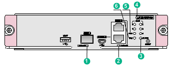
Figure 8-1 LSQM3SUPA0 MPU LEDs
|
(1) Fiber management Ethernet port LED |
(2) Copper management Ethernet port LED |
|
(3) Active/standby state LED |
(4) Card status LEDs |
|
(5) Power module status LED |
(6) Fan tray status LED (FAN) |
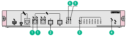
Figure 8-2 LSQM1MPUSA0 MPU LEDs
|
(1) Copper management Ethernet port LEDs |
(2) Fiber management Ethernet port LED |
|
(3) Card status LEDs |
(4) Active/standby state LED |
|
(5) Fan tray status LEDs |
(6) Power module status LEDs |
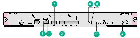
Figure 8-3 LSQM1SRP4Y06A0 MPU LEDs
|
(1) Copper management Ethernet port LEDs |
(2) SFP28 port LED |
|
(3) Card status LEDs |
(4) Active/standby state LED |
|
(5) Fan tray status LED |
(6) Power module status LED |
|
(7) Fiber management Ethernet port LED |
|
Management Ethernet port LEDs
Fiber management Ethernet port LED
The MPUs provide a LED for each fiber management Ethernet port to indicate its link status and data forwarding status.
Table 8-2 Fiber management Ethernet port LED description
|
LED status |
Description |
|
Flashing green |
A link is present, and the port is receiving or sending data. |
|
Steady green |
A link is present. |
|
Off |
No link is present. |
Copper management Ethernet port LEDs
The MPUs provide a pair of LEDs (LINK and ACT) for each copper management Ethernet port to indicate its link status and data forwarding status.
Table 8-3 Copper management Ethernet port LED description
|
LINK LED status |
ACT LED status |
Description |
|
On |
Flashing |
A link is present, and the port is receiving or sending data. |
|
On |
Off |
A link is present. |
|
Off |
Off |
No link is present. |
Power module status LEDs
On the MPUs available for the device, two types of power module status LEDs exist.
· A pair of power module status LEDs (PWR OK and FAIL). See Table 8-4 for the LED description.
· A single power module status LED (PWR). See Table 8-5 for the LED description.
Table 8-4 Description for the power module status LEDs
|
PWR OK LED status |
PWR FAIL LED status |
Description |
|
On |
Off |
All power modules are operating correctly. |
|
Off |
On |
A power module is not outputting power because one of the following conditions exists: · The power module is faulty or switched off. · The power cord is disconnected. · The power source is not supplying power. |
|
Off |
Off |
· No power modules are installed in the chassis. · No power modules are outputting power because one of the following conditions exists: ¡ The power modules are faulty or switched off. ¡ The power cords are disconnected. ¡ The power source is not supplying power. |
Table 8-5 Description for the power module status LED
|
PWR LED status (OK/FAIL) |
Description |
|
Steady green |
All power modules are operating correctly. |
|
Steady red |
A power module is not outputting power because one of the following conditions exists: · The power module is faulty or switched off. · The power cord is disconnected. · The power source is not supplying power. |
|
Off |
· No power modules are installed in the chassis. · No power modules are outputting power because one of the following conditions exists: ¡ The power modules are faulty or switched off. ¡ The power cords are disconnected. ¡ The power source is not supplying power. |
Fan tray status LEDs
On the MPUs available for the device, two types of fan tray status LEDs exist.
· A pair of fan tray status LEDs (FAN OK and FAIL). See Table 8-6 for the LED description.
· A single fan tray status LED (FAN OK/FAIL). See Table 8-7 for the LED description.
Table 8-6 Description for the fan tray status LEDs
|
FAN OK LED status |
FAN FAIL LED status |
Description |
|
On |
Off |
The fan tray is operating correctly. |
|
Off |
On |
A fan problem has occurred or the fan tray is not in position. |
|
Off |
Off |
The switch is not powered on. |
Table 8-7 Description for the fan tray status LED
|
FAN LED status (OK/FAIL) |
Description |
|
Steady green |
The fan tray is operating correctly. |
|
Steady red |
A fan problem has occurred or the fan tray is not in position. |
|
Off |
The switch is not powered on. |
Card status LEDs
On the MPUs available for the device, two types of card status LEDs exist.
· A single card status LED (SLOT RUN/ALM). See Table 8-8 for the LED description.
· A pair of card status LEDs (RUN and ALM). See Table 8-9 for the LED description.
Table 8-8 Description for the card status LED
|
SLOT LED status (RUN/ALM) |
Description |
|
Flashing green |
The card is operating correctly. |
|
Flashing green (4 Hz) |
The card is loading software. If the LED flashes continuously, the software versions of the switch and the card do not match. |
|
Steady red |
The card is starting up or faulty. |
|
Flashing red |
The temperature of the card has exceeded the upper warning threshold or has dropped below the lower warning threshold. |
|
Off |
No card is present. |
Table 8-9 Description for the card status LEDs
|
RUN LED status |
ALM LED status |
Description |
|
Flashing (0.5 Hz) |
Off |
The card is operating correctly. |
|
Fast flashing (4 Hz) |
On |
The card is loading software. If the LED flashes continuously, the software versions of the switch and the card do not match. |
|
Flashing (0.5 Hz) |
Slow flashing (0.25 Hz) |
The temperature of the card has exceeded the upper warning threshold or has dropped below the lower warning threshold. |
|
On |
On |
The card is starting up or faulty. |
|
Off |
Off |
No card is present. |
|
|
NOTE: The ALM LED lights for a period of time at the initial phase of the system startup. |
Active/standby state LED
Table 8-10 MPU active/standby state LED description
|
ACTIVE LED status |
Description |
|
On |
The MPU is in active state. |
|
Off |
· The MPU is in standby state. · The MPU is faulty. Observe also the status LED for the MPU to determine whether the MPU is faulty. |
SFP28 port LEDs
The MPUs provide a SFP28 port LED to indicate the link status and data receiving/forwarding status of the port.
Table 8-11 SFP28 port LED description
|
LED status |
Description |
|
Flashing |
The port is receiving or sending data. |
|
On |
A link is present. |
|
Off |
No link is present. |
Service module LEDs
RJ-45 Ethernet port LEDs
Table 8-12 RJ-45 Ethernet port LED description
|
LED status |
Description |
|
Flashing |
The port is receiving or sending data. |
|
On |
A link is present. |
|
Off |
No link is present. |
Combo interface LEDs
A combo interface contains an SFP port and an RJ-45 Ethernet port. Only one port of a combo interface is active at a time. By default, the port with the smaller number is active.
The service modules provide a LED for each combo interface to indicate the link status and data receiving/forwarding status of the interface.
Table 8-13 Combo interface LED description
|
LED status |
Description |
|
Flashing |
The interface is receiving or sending data. |
|
On |
A link is present. |
|
Off |
No link is present. |
|
|
NOTE: To use the inactive port of a combo interface, execute the undo shutdown command to activate the port. The other port of the combo interface is then automatically shut down and becomes inactive. |
SFP port LEDs
Table 8-14 SFP port LED description
|
LED status |
Description |
|
Flashing |
The port is receiving or sending data. |
|
On |
A link is present. |
|
Off |
No link is present. |
SFP+ port LEDs
The service modules provide a LED for each SFP+ port LED to indicate the link status and data receiving/forwarding status of the port.
Table 8-15 SFP+ port LED description
|
Status |
Description |
|
Flashing green |
The port is receiving or sending data at 10 Gbps. |
|
Flashing yellow |
The port is receiving or sending data at 1000 Mbps. |
|
On |
A link is present. |
|
Off |
No link is present. |
QSFP+ port LEDs
The service modules provide a LED for each QSFP+ port to indicate the link status and data receiving/forwarding status of the port.
Table 8-16 QSFP+ port LED description
|
Status |
Description |
|
Flashing |
The port is receiving or sending data. |
|
On |
A link is present. |
|
Off |
No link is present. |
|
|
NOTE: The color of the QSFP+ port LED indicates support of the port for 100-GE/40-GE switchover as follows: · Yellow—The port supports 100-GE/40-GE switchover. · Green—The port does not support 100-GE/40-GE switchover. |
QSFP28 port LEDs
The service modules provide a LED for each QSFP28 port to indicate the link status and data receiving/forwarding status of the port.
Table 8-17 QSFP28 port LED description
|
LED status |
Description |
|
Flashing |
The port is receiving or sending data. |
|
On |
A link is present. |
|
Off |
No link is present. |
|
|
NOTE: The color of the QSFP28 port LED indicates the port speed as follows: · Green—100 Gbps. · Yellow—Less than 100 Gbps. |
EPON port LEDs
The service modules provide a LED for each EPON port to indicate the link status and data receiving/forwarding status of the port.
Table 8-18 EPON port LED description
|
LED status |
Description |
|
On |
The connected ONU has been successfully registered. |
|
Off |
The connected ONU is not registered, or no ONU is connected. |
Power module LEDs
PSR320-A
A PSR320-A power module provides a status LED to indicate its operating status.
Table 8-19 PSR320-A power module LED description
|
LED |
Status |
Description |
|
Status LED |
Green |
Normal operation |
|
Red |
Abnormal operation. Possible reasons include: · A power module alarm (such as input undervoltage, output short-circuit, output overcurrent, output overvoltage, or overtemperature) has occurred and the power module has entered protection state. · A power module fan failure has occurred. |
|
|
Off |
Abnormal power input. Possible reasons include: · The power module is faulty. · The power cord is disconnected. · The external power supply system is not available. The power module is switched off. |
PSR650-A/PSR650-D/PSR1200-A/PSR1200-D
The PSR650-A, PSR650-D, PSR1200-A, and PSR1200-D power modules each provide a status LED to indicate their operating status.
Table 8-20 PSR650-A/PSR650-D/PSR1200-A/PSR1200-D power module LEDs description
|
LED |
Status |
Description |
|
Status LED |
Green |
Normal operation |
|
Red |
Abnormal operation. Possible reasons include: · A power module alarm (such as input undervoltage, output short-circuit, output overcurrent, output overvoltage, or overtemperature) has occurred and the power module has entered protection state. · A power module fan failure has occurred. |
|
|
Off |
Abnormal power input. Possible reasons include: · The power module is faulty. · The power cord is disconnected. · The external power supply system is not available. The power module is switched off. |
PSR650C-12A/PSR650C-12D/PSR1400-A/PSR2500-12AHD/PSR2500-12D
The PSR650C-12A, PSR650C-12D, PSR1400-A, PSR2500-12AHD, and PSR2500-12D power modules each provide three LEDs INPUT, OUTPUT, and FAN to indicate their operating status.
Table 8-21 PSR650C-12A/PSR650C-12D/PSR1400-A/PSR2500-12AHD/PSR2500-12D power module LEDs description
|
LED |
Status |
Description |
|
INPUT |
Green |
Normal power input |
|
Red |
Abnormal power input. The input voltage is out of the rated voltage range (input undervoltage or overvoltage). |
|
|
Off |
· The power module is faulty. · No power input. Possible reasons include: ¡ The power cord is disconnected. ¡ The external power supply system is not available. |
|
|
OUTPUT |
Green |
Normal power output |
|
Red |
Abnormal power output. Possible reasons include: · A power module alarm (such as input undervoltage, output short-circuit, output overcurrent, output overvoltage, overtemperature, or fan failure) has occurred and the power module has entered protection state. · The power module is switched off. |
|
|
Off |
· The power module is faulty. · No power input. Possible reasons include: ¡ The power cord is disconnected. ¡ The external power supply system is not available. |
|
|
FAN |
Green |
Normal fan operation |
|
Red |
Abnormal fan operation. Possible reasons include: · A power module fan failure has occurred. · The power module is switched off. |
|
|
Off |
· The power module is faulty. · The power module does not have power input. Possible reasons include: ¡ The power cord is disconnected. ¡ The external power supply system is not available. |
PSR1400-D
A PSR1400-D power module provides four LEDs INPUT, OUTPUT, FAN, and PoE to indicate its operating status.
Table 8-22 PSR1400-D power module LED description
|
LED |
Status |
Description |
|
INPUT |
Green |
The power is being input correctly, and the system power output switch is turned on. |
|
Red |
A power input problem has occurred because the input voltage is out of the rated voltage range. |
|
|
Off |
One of the following conditions might exist: · The power module is faulty. · The power cord is disconnected. · The power source is not supplying power. · The system power output switch is turned off. |
|
|
OUTPUT |
Green |
The power is being output correctly. |
|
Red |
A power output problem has occurred because the power module generates an alarm and enters the protection state due to output short-circuit, output overcurrent, output overvoltage, or overtemperature. |
|
|
Off |
One of the following conditions might exist: · The power module is faulty. · The power cord is disconnected. · The power source is not supplying power. · The system power output switch is turned off. |
|
|
FAN |
Green |
The fans are operating correctly. |
|
Red |
The fans are operating incorrectly because a fan failure has occurred. |
|
|
Off |
One of the following conditions might exist: · The power module is faulty. · The power cord is disconnected. · The power source is not supplying power. · The system power output switch is turned off. |
|
|
PoE |
Green |
The PoE power is being output correctly. |
|
Red |
A PoE power output problem has occurred because the PoE output voltage is out of the rated voltage range. |
|
|
Off |
No PoE power is being output because one of the following conditions might exist: · The power module is faulty. · The power cord is disconnected. · The power source is not supplying power. · The PoE power output switch is turned off. |
PSR1400-12D1
A PSR1400-12D1 power module provides three LEDs INPUT, OUTPUT, and FAN to indicate its operating status.
Table 8-23 PSR1400-12D1 power module LEDs description
|
LED |
Status |
Description |
|
INPUT |
Green |
Normal power input. |
|
Red |
Abnormal power input. The input voltage is out of the rated voltage range. |
|
|
Off |
· The power module is faulty. · No power input. Possible reasons include: ¡ The power cord is disconnected. ¡ The external power supply system is not available. · The system power output switch is turned off. |
|
|
OUTPUT |
Green |
Normal power output |
|
Red |
Abnormal power output. A power module alarm (such as output short-circuit, output overcurrent, output overvoltage, or overtemperature) has occurred and the power module has entered protection state. |
|
|
Off |
· The power module is faulty. · No power input. Possible reasons include: ¡ The power cord is disconnected. ¡ The external power supply system is not available. · The system power output switch is turned off. |
|
|
FAN |
Green |
Normal fan operation |
|
Red |
Abnormal fan operation. A power module fan failure has occurred. |
|
|
Off |
· The power module is faulty. · The power module does have power input. Possible reasons include: ¡ The power cord is disconnected. ¡ The external power supply system is not available. · The system power output switch is turned off. |
PSR2800-ACV
A PSR2800-ACV power module provides five LEDs INPUT, OUTPUT, FAN, PoE INPUT, and PoE OUTPUT to indicate its operating status.
Table 8-24 PSR2800-ACV power module LED description
|
LED |
Status |
Description |
|
INPUT |
Green |
Normal power input. |
|
Red |
Abnormal power input. The input voltage is out of the rated voltage range. |
|
|
Off |
· The power module is faulty. · No power input. Possible reasons include: ¡ The system input power cord is disconnected. ¡ The external power supply system is not available. |
|
|
OUTPUT |
Green |
Normal power output |
|
Red |
Abnormal power output. Possible reasons include: · A power module alarm (such as input undervoltage, output short-circuit, output overcurrent, output overvoltage, or overtemperature) has occurred and the power module has entered protection state. · The system power switch is turned off. |
|
|
Off |
· The power module is faulty. · No power input. Possible reasons include: ¡ The system input power cord is disconnected. ¡ The external power supply system is not available. |
|
|
FAN |
Green |
Normal fan operation |
|
Red |
Abnormal fan operation. Possible reasons include: · A power module fan failure has occurred. · The system power switch is turned off. |
|
|
Off |
· The power module is faulty. · The power module does have power input. Possible reasons include: ¡ The system input power cord is disconnected. ¡ The external power supply system is not available. |
|
|
PoE INPUT |
Green |
Normal PoE power input |
|
Red |
Abnormal PoE power input. The PoE input voltage is out of the rated voltage range. |
|
|
Off |
No PoE power input. Possible reasons include: · The power module is faulty. · The PoE input power cord is disconnected. · The external power supply system is not available. |
|
|
PoE OUTPUT |
Green |
Normal PoE power output |
|
Red |
Abnormal PoE power output. Possible reasons include: · The PoE output voltage is out of the rated voltage range. · The PoE power switch is turned off. |
|
|
Off |
No PoE power output. Possible reasons include: · The power module is faulty. · The PoE input power cord is disconnected. · The external power supply system is not available. |
PSR6000-ACV
Table 8-25 PSR6000-ACV power module LED description
|
LED |
Status |
Description |
|
SYS IN |
Green |
Normal system power input |
|
Red |
Abnormal system power input. The system power input voltage is out of the rated voltage range. |
|
|
Off |
· The power module is faulty. · No system power input. Possible reasons include: ¡ The system input power cord is disconnected. ¡ The external power supply system is not available. |
|
|
SYS OUT |
Green |
Normal system power output |
|
Red |
Abnormal system power output. Possible reasons include: · A power module alarm (such as output short-circuit, output overcurrent, output overvoltage, or overtemperature) has occurred and the power module has entered protection state. · The SYS power switch is turned off. |
|
|
Off |
· The power module is faulty. · No system power input. Possible reasons include: ¡ The system input power cord is disconnected. ¡ The external power supply system is not available. |
|
|
SYS FAN |
Green |
Normal system fan operation. |
|
Red |
Abnormal system fan operation. Possible reasons include: · A system fan failure has occurred. · The SYS power switch is turned off. |
|
|
Off |
· The power module is faulty. · No system power input. Possible reasons include: ¡ The system input power cord is disconnected. ¡ The external power supply system is not available. |
|
|
PoE IN1 |
Green |
Normal PoE1 power input. |
|
Red |
Abnormal PoE1 power input. The PoE1 power input voltage is out of the rated voltage range. |
|
|
Off |
No PoE1 power input. Possible reasons include: · The power module is faulty. · The PoE1 input power cord is disconnected. · The external power supply system is not available. |
|
|
PoE IN2 |
Green |
Normal PoE2 power input. |
|
Red |
Abnormal PoE2 power input. The PoE2 power input voltage is out of the rated voltage range. |
|
|
Off |
No PoE2 power input. Possible reasons include: · The power module is faulty. · The PoE2 input power cord is disconnected. · The external power supply system is not available. |
|
|
Green |
Normal PoE3 power input. |
|
|
Red |
Abnormal PoE3 power input. The PoE3 power input voltage is out of the rated voltage range. |
|
|
Off |
No PoE3 power input. Possible reasons include: · The power module is faulty. · The PoE3 input power cord is disconnected. · The external power supply system is not available. |
|
|
PoE OUT |
Green |
Normal PoE power output |
|
Red |
Abnormal PoE power output. Possible reasons include: · A power module alarm (such as output short-circuit, output overcurrent, output overvoltage, or overtemperature) has occurred and the power module has entered protection state. · The PoE power switch is turned off. |
|
|
Off |
No PoE power output. Possible reasons include: · The power module is faulty. · The PoE 1, PoE 2, and PoE 3 input power cords are all disconnected. · The external power supply system is not available. |
|
|
PoE FAN |
Green |
Normal PoE fan operation |
|
Red |
Abnormal PoE fan operation. Possible reasons include: · A PoE fan failure has occurred. · The PoE power switch is turned off. |
|
|
Off |
No PoE power input. Possible reasons include: · The power module is faulty. · The PoE 1, PoE 2, and PoE 3 input power cords are all disconnected. · The external power supply system is not available. |
