- Table of Contents
- Related Documents
-
| Title | Size | Download |
|---|---|---|
| 01-Text | 911.16 KB |
Contents
Configuration restrictions and guidelines
Setting the interval to send advertisement packets
Setting the port shutdown mode
Configuring DLDP authentication
Displaying and maintaining DLDP
Automatically shutting down unidirectional links
Manually shutting down unidirectional links
Router priority in a VRRP group
Virtual MAC address assignment
IPv4 VRRP configuration task list
Specifying an IPv4 VRRP operating mode·
Specifying the IPv4 VRRP version
Creating a VRRP group and assigning a virtual IP address
Configuring the router priority, preemptive mode, and tracking function
Configuring IPv4 VRRP packet attributes
Enabling SNMP notifications for VRRP
Displaying and maintaining IPv4 VRRP
IPv4 VRRP configuration examples
Single VRRP group configuration example
Multiple VRRP groups configuration example
VRRP load balancing configuration example
Multiple masters appear in a VRRP group
BFD session modes and operating modes
Configuring BFD basic functions
Configuring control packet mode
Displaying and maintaining BFD
Collaboration application example·
Associating the Track module with a detection module
Associating Track with interface management
Associating the Track module with an application module
Associating Track with static routing·
Displaying and maintaining track entries
VRRP-Track-NQA collaboration configuration example
Configuring BFD for a VRRP backup to monitor the master
Configuring BFD for the VRRP master to monitor the uplinks
Static routing-Track-BFD collaboration configuration example
VRRP-Track-interface management collaboration configuration example
Configuring DLDP
Overview
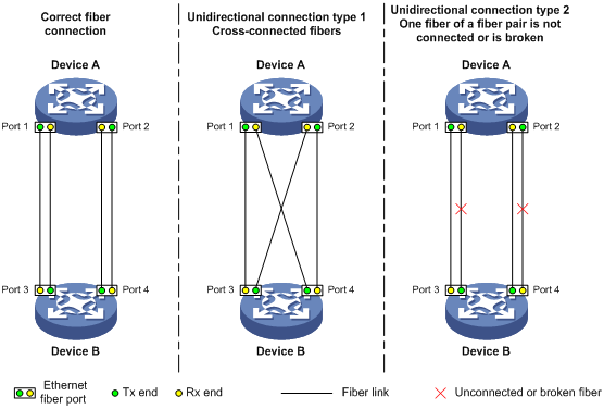
Unidirectional links occur when one end of a link can receive packets from the other end, but the other end cannot receive packets sent by the first end.
Unidirectional fiber links include the following types:
· Occur when fibers are cross-connected.
· Occur when a fiber is not connected at one end or when one fiber of a fiber pair gets broken.
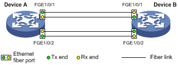
Figure 1 shows a correct fiber connection and the two types of unidirectional fiber connections.
Figure 1 Correct and incorrect fiber connections
Physical layer detection mechanisms, such as auto-negotiation, can detect physical signals and faults. They cannot detect communication failures for unidirectional links where the physical layer state is connected.
As a data link layer protocol, the Device Link Detection Protocol (DLDP) detects whether the fiber link or twisted-pair link is correctly connected at the link layer, and whether the two ends can exchange packets correctly. When DLDP detects unidirectional links, it can automatically shut down the faulty port to avoid network problems. Alternatively, a user can manually shut down the faulty port. DLDP cooperates with physical layer protocols to monitor link status and avoid physical and logical unidirectional links.
Basic concepts
DLDP neighbor states
If port A and B are on the same link and port A can receive link-layer packets from port B, port B is a DLDP neighbor of port A. Two ports that can exchange packets are neighbors.
Table 1 DLDP neighbor states
|
DLDP timer |
Description |
|
Confirmed |
The link to a DLDP neighbor is bidirectional. |
|
Unconfirmed |
The state of the link to a newly discovered neighbor is not determined. |
DLDP port states
A DLDP-enabled port is called a "DLDP port." A DLDP port can have multiple neighbors, and its state depends on the DLDP neighbor state.
Table 2 DLDP port states
|
State |
Description |
|
Initial |
DLDP is enabled on the port, but is disabled globally. |
|
Inactive |
DLDP is enabled on the port and globally, and the link is physically down. |
|
Bidirectional |
DLDP is enabled on the port and globally, and at least one neighbor in Confirmed state exists. |
|
Unidirectional |
DLDP is enabled on the port and globally, and no neighbor in Confirmed state exists. In this state, a port does not send or receive packets other than DLDP packets any more. |
DLDP timers
Table 3 DLDP timers
|
DLDP timer |
Description |
|
Advertisement timer |
Advertisement packet sending interval (the default is 5 seconds and is configurable). |
|
Probe timer |
Probe packet sending interval. This timer is set to 1 second. |
|
Echo timer |
The Echo timer is triggered when a probe is launched for a new neighbor. This timer is set to 10 seconds. |
|
Entry timer |
When a new neighbor joins, a neighbor entry is created and the corresponding entry timer is triggered if the neighbor is in Confirmed state. When an Advertisement is received, the device updates the corresponding neighbor entry and the Entry timer. The setting of an Entry timer is three times that of the Advertisement timer. |
|
Enhanced timer |
The Enhanced timer is triggered, together with the Echo timer, when the Entry timer expires. Enhanced timer is set to 1 second. |
|
DelayDown timer |
If a port is physically down, the device triggers the DelayDown timer (the default is 1 second and is configurable), rather than removing the corresponding neighbor entry. When the DelayDown timer expires, the device removes the corresponding DLDP neighbor information if the port is down, and does not perform any operation if the port is up. |
|
RecoverProbe timer |
This timer is set to 2 seconds. A port in the Unidirectional state regularly sends RecoverProbe packets to detect whether a unidirectional link has been restored to bidirectional. |
DLDP authentication mode
You can use DLDP authentication to prevent network attacks and illegal detecting.
Table 4 DLDP authentication mode
|
Authentication mode |
Processing at the DLDP packet sending side |
Processing at the DLDP packet receiving side |
|
Non-authentication |
The sending side sets the Authentication field of DLDP packets to 0. |
The receiving side checks the authentication information of received DLDP packets and drops packets where the authentication information conflicts with the local configuration. |
|
Plaintext authentication |
The sending side sets the Authentication field to the password configured in plain text. |
|
|
MD5 authentication |
The sending side encrypts the user configured password using MD5 algorithm, assigns the digest to the Authentication field. |
How DLDP works
Detecting one neighbor
When two devices are connected through an optical fiber or network cable, enable DLDP to detect unidirectional links to the neighbor. The following illustrates the unidirectional link detection process in two cases:
· Unidirectional links occur before you enable DLDP.
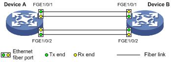
Figure 2 Cross-connected fibers
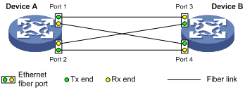
As shown in Figure 2, before you enable DLDP, the optical fibers between Device A and Device B are cross-connected. After you enable DLDP, the four ports are all up and in Unidirectional state, and they send RecoverProbe packets. Take Port 1 as an example to illustrate the unidirectional link detection process:
a. Port 1 receives the RecoverProbe packet from Port 4, and returns a RecoverEcho packet.
b. Port 4 cannot receive any RecoverEcho packet from Port 1, so Port 4 cannot become the neighbor of Port 1.
c. Port 3 can receive the RecoverEcho packet from Port 1, but Port 3 is not the intended destination, so Port 3 cannot become the neighbor of Port 1.
The same process occurs on the other three ports. The four ports are all in Unidirectional state.
· Unidirectional links occur after you enable DLDP.
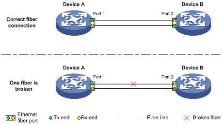
As shown in Figure 3, Device and Device B are connected through an optical fiber. After you enable DLDP, Port 1 and Port 2 establish the bidirectional neighborship in the following way:
a. Port 1 that is physically up enters the Unidirectional state and sends a RecoverProbe packet.
b. After receiving the RecoverProbe packet, Port 2 returns a RecoverEcho packet.
c. After Port 1 receives the RecoverEcho packet and detects that the neighbor information in the packet matches the local information, Port 1 establishes the neighborship with Port 2 and transits to the Bidirectional state. Port 1 then starts the Entry timer and periodically sends Advertisement packets.
d. After Port 2 receives the Advertisement packet, it establishes the Unconfirmed neighborship with Port 1. Port 2 then starts the Echo timer and Probe timer, and periodically sends Probe packets.
e. After receiving the Probe packet, Port 1 returns an Echo packet.
f. After Port 2 receives the Echo packet and detects that the neighbor information in the packet matches the local information, the neighbor state of Port 1 becomes Confirmed. Port 2 then transits to the Bidirectional state, starts the Entry timer, and periodically sends Advertisement packets.
The bidirectional neighborship between Port 1 and Port 2 is now established.
After that, when Port 2's Rx end fails to receive signals, Port 2 is physically down and enters the Inactive state. Because Port 2's Tx end can still send signals to Port 1, Port 1 stays up. After the Entry timer for Port 2 expires, Port 1 starts the Enhanced timer and Echo timer, and sends a probe packet to Port 2. Because Port 1's Tx line is broken, Port 1 cannot receive the Echo packet from Port 2 after the Echo timer expires. Port 1 then enters the Unidirectional state, and sends a Disable packet to Port 2. At the same time, Port 1 deletes the neighborship with Port 2, and starts the RecoverProbe timer. Port 2 stays in Inactive state during this process.
Detecting multiple neighbors
When multiple devices are connected through a hub, enable DLDP on all interfaces connected to the hub to detect unidirectional links among the neighbors. When no Confirmed neighbor exists, an interface enters the Unidirectional state.
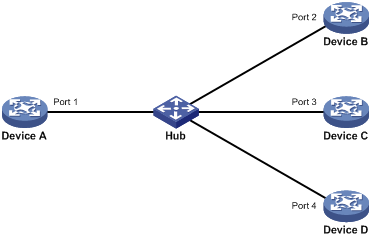
As shown in Figure 4, Device A through Device D are connected through a hub, and enabled with DLDP. When Port 1, Port 2, and Port 3 detect that the link to Port 4 fails, they deletes the neighborship with Port 4, but stay in Bidirectional state.
Configuration restrictions and guidelines
For DLDP to operate correctly, enable DLDP on both sides and make sure these settings are consistent: the interval to send Advertisement packets, DLDP authentication mode, and password.
DLDP configuration task list
|
Tasks at a glance |
|
(Required.) Enabling DLDP |
|
(Optional.) Setting the interval to send advertisement packets |
|
(Optional.) Setting the DelayDown timer |
|
(Optional.) Setting the port shutdown mode |
|
(Optional.) Configuring DLDP authentication |
Enabling DLDP
To correctly configure DLDP on the device, you must enable DLDP globally and on each port.
To enable DLDP:
|
Command |
Remarks |
|
|
1. Enter system view. |
system-view |
N/A |
|
2. Enable DLDP globally. |
dldp global enable |
By default, DLDP is globally disabled. |
|
3. Enter Layer 2 or Layer 3 Ethernet interface view. |
interface interface-type interface-number |
N/A |
|
4. Enable DLDP. |
dldp enable |
By default, DLDP is disabled on an interface. |
Setting the interval to send advertisement packets
To make sure DLDP can detect unidirectional links before network performance deteriorates, set the advertisement interval appropriate for your network environment. (As a best practice, use the default interval.)
To set the Advertisement packet sending interval:
|
Step |
Command |
Remarks |
|
1. Enter system view. |
system-view |
N/A |
|
2. Set the interval to send Advertisement packets. |
dldp interval time |
The default is 5 seconds. |
Setting the DelayDown timer
On some ports, when the Tx line fails, the port goes down and then comes up again, causing optical signal jitters on the Rx line. To avoid this problem, when a port goes down due to a Tx failure, the device triggers the DelayDown timer to prevent the corresponding neighbor entries from being removed. If the port remains down when the timer expires, the device removes the DLDP neighbor information. If the port goes up, the device takes no action.
To set the DelayDown timer:
|
Step |
Command |
Remarks |
|
1. Enter system view. |
system-view |
N/A |
|
2. Set the DelayDown timer. |
dldp delaydown-timer time |
The default is 1 second. The DelayDown timer setting applies to all DLDP-enabled ports. |
Setting the port shutdown mode
On detecting a unidirectional link, the ports can be shut down in one of the following modes:
· Auto mode—When a unidirectional link is detected, DLDP changes the DLDP port state to Unidirectional. The unidirectional port periodically sends RecoverProbe packets. When a correct RecoverEcho packet is received, the link is restored to a bidirectional link, and the port state changes from Unidirectional to Bidirectional. This process is called "link auto-recovery mechanism."
· Manual mode—When a unidirectional link is detected, DLDP does not shut down the port, and you need to manually shut it down. When the link state is restored to Bidirectional, you must manually bring up the port. If the network performance is low, the device is busy, or the CPU usage is high, use this mode to prevent normal links from being shut down because of false unidirectional link reports.
To set port shutdown mode:
|
Step |
Command |
Remarks |
|
1. Enter system view. |
system-view |
N/A |
|
2. Set port shutdown mode. |
dldp unidirectional-shutdown { auto | manual } |
The default mode is auto. |
Configuring DLDP authentication
You can guard your network against attacks and malicious probes by configuring an appropriate DLDP authentication mode, which can be plain text authentication or MD5 authentication. If your network is safe, you can choose not to authenticate.
To configure DLDP authentication:
|
Step |
Command |
Remarks |
|
1. Enter system view. |
system-view |
N/A |
|
2. Configure a DLDP authentication mode. |
dldp authentication-mode { md5 | none | simple } |
The default authentication mode is none. |
|
3. Configure the password for DLDP authentication. |
dldp authentication-password { cipher cipher | simple simple } |
By default, no password is configured for DLDP authentication. If you do not configure the authentication password after you configure the authentication mode, the authentication mode is none no matter which authentication mode you configure. |
Displaying and maintaining DLDP
Execute display commands in any view and the reset command in user view.
|
Task |
Command |
|
Display the DLDP configuration globally and of a port. |
display dldp [ interface interface-type interface-number ] |
|
Display the statistics on DLDP packets passing through a port. |
display dldp statistics [ interface interface-type interface-number ] |
|
Clear the statistics on DLDP packets passing through a port. |
reset dldp statistics [ interface interface-type interface-number ] |
DLDP configuration examples
Automatically shutting down unidirectional links
Network requirements
As shown in Figure 5, Device A and Device B are connected with two fiber pairs.
Configure DLDP to automatically shut down the faulty port upon detecting a unidirectional link, and automatically bring up the port after you clear the fault.
Configuration procedure
1. Configure Device A:
# Enable DLDP globally.
<DeviceA> system-view
[DeviceA] dldp global enable
# Enable DLDP on FortyGigE 1/0/1.
[DeviceA] interface fortygige 1/0/1
[DeviceA-FortyGigE1/0/1] dldp enable
[DeviceA-FortyGigE1/0/1] quit
# Enable DLDP on FortyGigE 1/0/2.
[DeviceA] interface fortygige 1/0/2
[DeviceA-FortyGigE1/0/2] dldp enable
[DeviceA-FortyGigE1/0/2] quit
# Set the port shutdown mode to auto.
[DeviceA] dldp unidirectional-shutdown auto
2. Configure Device B:
# Enable DLDP globally.
<DeviceB> system-view
[DeviceB] dldp global enable
# Enable DLDP on FortyGigE 1/0/1.
[DeviceB] interface fortygige 1/0/1
[DeviceB-FortyGigE1/0/1] dldp enable
[DeviceB-FortyGigE1/0/1] quit
# Enable DLDP on FortyGigE 1/0/2.
[DeviceB] interface fortygige 1/0/2
[DeviceB-FortyGigE1/0/2] dldp enable
[DeviceB-FortyGigE1/0/2] quit
# Set the port shutdown mode to auto.
[DeviceB] dldp unidirectional-shutdown auto
3. Verify the configuration:
After the configurations are complete, you can use the display dldp command to display the DLDP configuration globally and on ports.
# Display the DLDP configuration globally and on all the DLDP-enabled ports of Device A.
[DeviceA] display dldp
DLDP global status: Enabled
DLDP advertisement interval: 5s
DLDP authentication-mode: None
DLDP unidirectional-shutdown mode: Auto
DLDP delaydown-timer value: 1s
Number of enabled ports: 2
Interface FortyGigE1/0/1
DLDP port state: Bidirectional
Number of the port’s neighbors: 1
Neighbor MAC address: 0023-8956-3600
Neighbor port index: 1
Neighbor state: Confirmed
Neighbor aged time: 11s
Interface FortyGigE1/0/2
DLDP port state: Bidirectional
Number of the port’s neighbors: 1
Neighbor MAC address: 0023-8956-3600
Neighbor port index: 2
Neighbor state: Confirmed
Neighbor aged time: 12s
The output shows that both FortyGigE 1/0/1 and FortyGigE 1/0/2 are in Bidirectional state, which means both links are bidirectional.
# Enable the monitoring of logs on the current terminal on Device A, and set the lowest level of the logs that can be output to the current terminal to 6.
[DeviceA] quit
<DeviceA> terminal monitor
<DeviceA> terminal logging level 6
The following log information is displayed on Device A:
<DeviceA>%Jul 11 17:40:31:089 2013 DeviceA IFNET/3/PHY_UPDOWN: FortyGigE1/0/1 link status is DOWN.
%Jul 11 17:40:31:091 2013 DeviceA IFNET/5/LINK_UPDOWN: Line protocol on the interface FortyGigE1/0/1 is DOWN.
%Jul 11 17:40:31:677 2013 DeviceA IFNET/3/PHY_UPDOWN: FortyGigE1/0/2 link status is DOWN.
%Jul 11 17:40:31:678 2013 DeviceA IFNET/5/LINK_UPDOWN: Line protocol on the interface FortyGigE1/0/2 is DOWN.
%Jul 11 17:40:38:544 2013 DeviceA IFNET/3/PHY_UPDOWN: FortyGigE1/0/1 link status is UP.
%Jul 11 17:40:38:836 2013 DeviceA IFNET/3/PHY_UPDOWN: FortyGigE1/0/2 link status is UP.
The output shows that the port status of both FortyGigE 1/0/1 and FortyGigE 1/0/2 is down and then up, but the link status of them is always down.
# Display the DLDP configuration globally and of all the DLDP-enabled ports.
<DeviceA> display dldp
DLDP global status: Enabled
DLDP advertisement interval: 5s
DLDP authentication-mode: None
DLDP unidirectional-shutdown mode: Auto
DLDP delaydown-timer value: 1s
Number of enabled ports: 2
Interface FortyGigE1/0/1
DLDP port state: Unidirectional
Number of the port’s neighbors: 0 (Maximum number ever detected: 1)
Interface FortyGigE1/0/2
DLDP port state: Unidirectional
Number of the port’s neighbors: 0 (Maximum number ever detected: 1)
The output shows that the DLDP port status of both FortyGigE 1/0/1 and FortyGigE 1/0/2 is unidirectional, which indicates that DLDP detects unidirectional links on them and automatically shuts down the two ports.
The unidirectional links are caused by cross-connected fibers. Correct the fiber connections. As a result, the ports shut down by DLDP automatically recover, and Device A displays the following log information:
<DeviceA>%Jul 11 17:42:57:709 2013 DeviceA IFNET/3/PHY_UPDOWN: FortyGigE1/0/1 link status is DOWN.
%Jul 11 17:42:58:603 2013 DeviceA IFNET/3/PHY_UPDOWN: FortyGigE1/0/2 link status is DOWN.
%Jul 11 17:43:02:342 2013 DeviceA IFNET/3/PHY_UPDOWN: FortyGigE1/0/1 link status is UP.
%Jul 11 17:43:02:343 2013 DeviceA DLDP/6/DLDP_NEIGHBOR_CONFIRMED: A neighbor was confirmed on interface FortyGigE1/0/1. The neighbor's system MAC is 0023-8956-3600, and the port index is 1.
%Jul 11 17:43:02:344 2013 DeviceA DLDP/6/DLDP_LINK_BIDIRECTIONAL: DLDP detected a bidirectional link on interface FortyGigE1/0/1.
%Jul 11 17:43:02:353 2013 DeviceA IFNET/5/LINK_UPDOWN: Line protocol on the interface FortyGigE1/0/1 is UP.
%Jul 11 17:43:02:357 2013 DeviceA IFNET/3/PHY_UPDOWN: FortyGigE1/0/2 link status is UP.
%Jul 11 17:43:02:362 2013 DeviceA DLDP/6/DLDP_NEIGHBOR_CONFIRMED: A neighbor was confirmed on interface FortyGigE1/0/2. The neighbor's system MAC is 0023-8956-3600, and the port index is 2.
%Jul 11 17:43:02:362 2013 DeviceA DLDP/6/DLDP_LINK_BIDIRECTIONAL: DLDP detected a bidirectional link on interface FortyGigE1/0/2.
%Jul 11 17:43:02:368 2013 DeviceA IFNET/5/LINK_UPDOWN: Line protocol on the interface FortyGigE1/0/2 is UP.
The output shows that the port status and link status of both FortyGigE 1/0/1 and FortyGigE 1/0/2 are now up and their DLDP neighbors are determined.
Manually shutting down unidirectional links
Network requirements
As shown in Figure 6, Device A and Device B are connected with two fiber pairs.
Configure DLDP to detect unidirectional links. When a unidirectional link is detected, the administrator must manually shut down the port.
Configuration procedure
1. Configure Device A:
# Enable DLDP globally.
<DeviceA> system-view
[DeviceA] dldp enable
# Enable DLDP on FortyGigE 1/0/1.
[DeviceA] interface fortygige 1/0/1
[DeviceA-FortyGigE1/0/1] dldp enable
[DeviceA-FortyGigE1/0/1] quit
# Enable DLDP on FortyGigE 1/0/2.
[DeviceA] interface fortygige 1/0/2
[DeviceA-FortyGigE1/0/2] dldp enable
[DeviceA-FortyGigE1/0/2] quit
# Set the port shutdown mode to manual.
[DeviceA] dldp unidirectional-shutdown manual
2. Configure Device B:
# Enable DLDP globally.
<DeviceB> system-view
[DeviceB] dldp global enable
# Enable DLDP on FortyGigE 1/0/1.
[DeviceB] interface fortygige 1/0/1
[DeviceB-FortyGigE1/0/1] dldp enable
[DeviceB-FortyGigE1/0/1] quit
# Enable DLDP on FortyGigE 1/0/2.
[DeviceB] interface fortygige 1/0/2
[DeviceB-FortyGigE1/0/2] dldp enable
[DeviceB-FortyGigE1/0/2] quit
# Set the port shutdown mode to manual.
[DeviceB] dldp unidirectional-shutdown manual
3. Verify the configuration:
After the configurations are complete, you can use the display dldp command to display the DLDP configuration globally and on ports.
# Display the DLDP configuration globally and on all the DLDP-enabled ports of Device A.
[DeviceA] display dldp
DLDP global status: Enabled
DLDP advertisement interval: 5s
DLDP authentication-mode: None
DLDP unidirectional-shutdown mode: Manual
DLDP delaydown-timer value: 1s
Number of enabled ports: 2
Interface FortyGigE1/0/1
DLDP port state: Bidirectional
Number of the port’s neighbors: 1
Neighbor MAC address: 0023-8956-3600
Neighbor port index: 1
Neighbor state: Confirmed
Neighbor aged time: 11s
Interface FortyGigE1/0/2
DLDP port state: Bidirectional
Number of the port’s neighbors: 1
Neighbor MAC address: 0023-8956-3600
Neighbor port index: 2
Neighbor state: Confirmed
Neighbor aged time: 12s
The output shows that both FortyGigE 1/0/1 and FortyGigE 1/0/2 are in Bidirectional state, which means both links are bidirectional.
# Enable the monitoring of logs on the current terminal on Device A, and set the lowest level of the logs that can be output to the current terminal to 6.
[DeviceA] quit
<DeviceA> terminal monitor
<DeviceA> terminal logging level 6
The following log information is displayed on Device A:
<DeviceA>%Jul 12 08:29:17:786 2013 DeviceA IFNET/3/PHY_UPDOWN: FortyGigE1/0/1 link status is DOWN.
%Jul 12 08:29:17:787 2013 DeviceA IFNET/5/LINK_UPDOWN: Line protocol on the interface FortyGigE1/0/1 is DOWN.
%Jul 12 08:29:17:800 2013 DeviceA IFNET/3/PHY_UPDOWN: FortyGigE1/0/2 link status is DOWN.
%Jul 12 08:29:17:800 2013 DeviceA IFNET/5/LINK_UPDOWN: Line protocol on the interface FortyGigE1/0/2 is DOWN.
%Jul 12 08:29:25:004 2013 DeviceA IFNET/3/PHY_UPDOWN: FortyGigE1/0/1 link status is UP.
%Jul 12 08:29:25:005 2013 DeviceA IFNET/5/LINK_UPDOWN: Line protocol on the interface FortyGigE1/0/1 is UP.
%Jul 12 08:29:25:893 2013 DeviceA IFNET/3/PHY_UPDOWN: FortyGigE1/0/2 link status is UP.
%Jul 12 08:29:25:894 2013 DeviceA IFNET/5/LINK_UPDOWN: Line protocol on the interface FortyGigE1/0/2 is UP.
The output shows that the port status and link status of both FortyGigE 1/0/1 and FortyGigE 1/0/2 are down and then up.
# Display the DLDP configuration globally and of all the DLDP-enabled ports.
<DeviceA> display dldp
DLDP global status: Enabled
DLDP advertisement interval: 5s
DLDP authentication-mode: None
DLDP unidirectional-shutdown mode: Manual
DLDP delaydown-timer value: 1s
Number of enabled ports: 2
Interface FortyGigE1/0/1
DLDP port state: Unidirectional
Number of the port’s neighbors: 0 (Maximum number ever detected: 1)
Interface FortyGigE1/0/2
DLDP port state: Unidirectional
Number of the port’s neighbors: 0 (Maximum number ever detected: 1)
The output shows that the DLDP port status of both FortyGigE 1/0/1 and FortyGigE 1/0/2 is unidirectional, which indicates that DLDP detects unidirectional links on them but does not shut down the two ports.
The unidirectional links are caused by cross-connected fibers. Manually shut down the two ports:
# Shut down FortyGigE 1/0/1.
<DeviceA> system-view
[DeviceA] interface fortygige 1/0/1
[DeviceA-FortyGigE1/0/1] shutdown
The following log information is displayed on Device A:
[DeviceA-FortyGigE1/0/1]%Jul 12 08:34:23:717 2013 DeviceA IFNET/3/PHY_UPDOWN: FortyGigE1/0/1 link status is DOWN.
%Jul 12 08:34:23:718 2013 DeviceA IFNET/5/LINK_UPDOWN: Line protocol on the interface FortyGigE1/0/1 is DOWN.
%Jul 12 08:34:23:778 2013 DeviceA IFNET/3/PHY_UPDOWN: FortyGigE1/0/2 link status is DOWN.
%Jul 12 08:34:23:779 2013 DeviceA IFNET/5/LINK_UPDOWN: Line protocol on the interface FortyGigE1/0/2 is DOWN.
The output shows that the port status and link status of both FortyGigE 1/0/1 and FortyGigE 1/0/2 are now down.
# Shut down FortyGigE 1/0/2.
[DeviceA-FortyGigE1/0/1] quit
[DeviceA] interface fortygige 1/0/2
[DeviceA-FortyGigE1/0/2] shutdown
Correct the fiber connections and bring up the two ports:
# Bring up FortyGigE 1/0/2.
[DeviceA-FortyGigE1/0/2] undo shutdown
The following log information is displayed on Device A:
[DeviceA-FortyGigE1/0/2]%Jul 12 08:46:17:677 2013 DeviceA IFNET/3/PHY_UPDOWN: FortyGigE1/0/2 link status is UP.
%Jul 12 08:46:17:678 2013 DeviceA IFNET/5/LINK_UPDOWN: Line protocol on the interface FortyGigE1/0/2 is UP.
%Jul 12 08:46:17:959 2013 DeviceA DLDP/6/DLDP_NEIGHBOR_CONFIRMED: A neighbor was confirmed on interface FortyGigE1/0/2. The neighbor's system MAC is 0023-8956-3600, and the port index is 2.
%Jul 12 08:46:17:959 2013 DeviceA DLDP/6/DLDP_LINK_BIDIRECTIONAL: DLDP detected a bidirectional link on interface FortyGigE1/0/2.
The output shows that the port status and link status of FortyGigE 1/0/2 are now up and its DLDP neighbors are determined.
# Bring up FortyGigE 1/0/1.
[DeviceA-FortyGigE1/0/2] quit
[DeviceA] interface fortygige 1/0/1
[DeviceA-FortyGigE1/0/1] undo shutdown
The following log information is displayed on Device A:
[DeviceA-FortyGigE1/0/1]%Jul 12 08:48:25:952 2013 DeviceA IFNET/3/PHY_UPDOWN: FortyGigE1/0/1 link status is UP.
%Jul 12 08:48:25:952 2013 DeviceA DLDP/6/DLDP_NEIGHBOR_CONFIRMED: A neighbor was confirmed on interface FortyGigE1/0/1. The neighbor's system MAC is 0023-8956-3600, and the port index is 1.
%Jul 12 08:48:25:953 2013 DeviceA IFNET/5/LINK_UPDOWN: Line protocol on the interface FortyGigE1/0/1 is UP.
%Jul 12 08:48:25:953 2013 DeviceA DLDP/6/DLDP_LINK_BIDIRECTIONAL: DLDP detected a bidirectional link on interface FortyGigE1/0/1.
The output shows that the port status and link status of FortyGigE 1/0/1 are now up and its DLDP neighbors are determined.
Configuring VRRP
The term "interface" in this chapter refers to VLAN interfaces, Layer 3 Ethernet interfaces, Layer 3 aggregate interfaces, Layer 3 Ethernet subinterfaces, and Layer 3 aggregate subinterfaces. You can configure an Ethernet port as a Layer 3 interface by using the port link-mode route command (see Layer 2—LAN Switching Configuration Guide).
VRRP cannot be configured on member ports of aggregation groups.
Overview
Typically, you can configure a default gateway for every host on a LAN. All packets destined for other networks are sent through the default gateway. As shown in Figure 7, when the default gateway fails, no hosts can communicate with external networks.
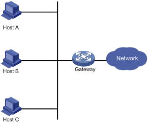
Using a default gateway facilitates your configuration but requires high availability. Using more egress gateways improves link availability but introduces the problem of routing among the egresses.
Virtual Router Redundancy Protocol (VRRP) is designed to address this issue. VRRP adds a group of network gateways to a VRRP group called a "virtual router." A VRRP group comprises one master and multiple backups, but has only one virtual IP address. The hosts on the subnet only need to configure this virtual IP address as their default network gateway for communicating with external networks.
The virtual IP address of the virtual router can be either an unused IP address on the subnet where the VRRP group resides or the IP address of an interface on a router in the VRRP group. In the latter case, the router is called the IP address owner. A VRRP group can have only one IP address owner.
VRRP avoids single points of failure and simplifies the configuration on hosts. When the master in the VRRP group on a multicast or broadcast LAN (for example, an Ethernet network) fails, another router in the VRRP group takes over. The switchover is complete without causing dynamic route recalculation, route re-discovery, gateway reconfiguration on the hosts, or traffic interruption.
VRRP operates in either of the following modes:
· Standard mode—Implemented based on RFCs. For more information, see "VRRP standard mode."
· Load balancing mode—Extends the VRRP standard mode to distribute load across VRRP group members. For more information, see "VRRP load balancing mode."
VRRP has two versions: VRRPv2 and VRRPv3. VRRPv2 and VRRPv3 support only IPv4 VRRP.
VRRP standard mode
In VRRP standard mode, only the master in the VRRP group can provide gateway service. When the master fails, the backup routers elect a new master to take over for nonstop gateway service.
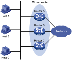
As shown in Figure 8, Router A, Router B, and Router C form a virtual router, which has its own IP address. Hosts on the subnet use the virtual router as the default gateway.
The router with the highest priority among the three routers is elected as the master, and the other two are backups.
Router priority in a VRRP group
VRRP determines the role (master or backup) of each router in a VRRP group by priority. A router with higher priority is more likely to become the master.
A VRRP priority can be in the range of 0 to 255, and a greater number represents a higher priority. Priorities 1 to 254 are configurable. Priority 0 is reserved for special uses, and priority 255 is for the IP address owner. The router acting as the IP address owner in a VRRP group always has a running priority of 255 and acts as the master as long as it operates correctly.
Preemption
A router in a VRRP group operates in either non-preemptive mode or preemptive mode:
· Non-preemptive mode—When a router in the VRRP group becomes the master, it acts as the master as long as it operates correctly, even if a backup router is later assigned a higher priority. Non-preemptive mode helps avoid frequent switchover between the master and backup routers.
· Preemptive mode—A backup starts a new master election and takes over as master when it detects that it has a higher priority than the current master. Preemptive mode makes sure the router with the highest priority in a VRRP group always acts as the master.
Authentication method
To avoid attacks from unauthorized users, VRRP member routers add authentication keys in VRRP packets to authenticate one another. VRRP provides the following authentication methods:
· Simple authentication
The sender fills an authentication key into the VRRP packet, and the receiver compares the received authentication key with its local authentication key. If the two authentication keys match, the received VRRP packet is legitimate. Otherwise, the received packet is illegitimate and gets discarded.
· MD5 authentication
The sender computes a digest for the packet to be sent by using the authentication key and MD5 algorithm, and saves the result in the VRRP packet. The receiver performs the same operation with the authentication key and MD5 algorithm, and compares the result with the content in the authentication header. If the results match, the received VRRP packet is legitimate. Otherwise, the received packet is illegitimate and gets discarded.
On a secure network, you can choose to not authenticate VRRP packets.
|
|
NOTE: IPv4 VRRPv3 does not support VRRP packet authentication. |
VRRP timers
Skew_Time
Skew_Time helps avoid the situation that multiple backups in a VRRP group become the master at the same time when the master in the VRRP group fails.
Skew_Time is not configurable and its value depends on the version of VRRP:
· In VRRPv2 (described in RFC 3768), Skew_Time is (256 – Router priority)/256.
· In VRRPv3 (described in RFC 5798), Skew_Time is ((256 – Router priority) × VRRP advertisement interval)/256.
VRRP advertisement interval
The master in a VRRP group periodically sends VRRP advertisements to declare its presence.
You can configure the interval at which the master sends VRRP advertisements. If a backup does not receive a new VRRP advertisement from the master when the timer (3 × VRRP advertisement interval + Skew_Time) expires, it regards that the master has failed and takes over as the master.
VRRP preemption delay timer
You can configure the VRRP preemption delay timer to avoid frequent state changes among members in a VRRP group and provide the backups enough time to collect information (such as routing information). In preempt mode, a backup does not immediately become the master after it receives an advertisement with lower priority than the local priority. Instead, it waits for a period of time (preemption delay time + Skew_Time) before taking over as the master.
Master election
Routers in a VRRP group determine their roles by priority. When a router joins a VRRP group, it has a backup role. The router role changes according to the following situations:
· If the backup does not receive any VRRP advertisement when the timer (3 × advertisement interval + Skew_Time) expires, it becomes the master.
· If the backup receives a VRRP advertisement with a greater or the same priority within the timer (3 × advertisement interval + Skew_Time), it remains a backup.
· If the backup receives a VRRP advertisement with a smaller priority within the timer (3 × advertisement interval + Skew_Time), it remains a backup when operating in non-preemptive mode, or becomes the master when operating in preemptive mode.
The elected master starts a VRRP advertisement interval to periodically send VRRP advertisements to notify the backups that it is operating correctly. Each of the backups starts a timer to wait for advertisements from the master.
After a backup receives a VRRP advertisement, it compares only the priority in the packet with its own priority.
When multiple routers in a VRRP group declare that they are the master because of network problems, the one with the highest priority becomes the master. If two routers have the same priority, the one with the highest IP address becomes the master.
VRRP tracking
To enable VRRP tracking, configure the routers in the VRRP group to operate in preemptive mode first, so that only the router with the highest priority operates as the master for packet forwarding. For more information about track entries, see High Availability Configuration Guide.
The VRRP tracking function uses network quality analyzer (NQA) or bidirectional forwarding detection (BFD) to monitor the state of the master, and establishes the collaboration between the VRRP device state and NQA or BFD through the track function. It implements the following:
· Monitors the upstream link and changes the priority of the router according to the state of the link. If the upstream link fails, the hosts on the subnet cannot access external networks through the router and the state of the track entry becomes Negative. The priority of the master decreases by a specified value. Then, a router with a higher priority in the VRRP group becomes the master to maintain the proper communication between the hosts on the subnet and external networks.
· Monitors the state of the master on the backups. When the master fails, a backup immediately takes over as the master to ensure uninterrupted communication.
When the track entry changes from Negative to Positive or Notready, the router automatically restores its priority. For more information about track entries, see "Configuring Track."
VRRP application
Master/backup
In master/backup mode, only the master forwards packets, as shown in Figure 9. When the master fails, a new master is elected from among the backups. This mode requires only one VRRP group, and each router in the group has a different priority. The one with the highest priority becomes the master.
Figure 9 VRRP in master/backup mode
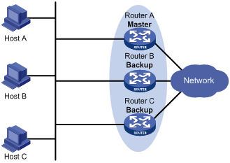
Assume that Router A is acting as the master to forward packets to external networks, and Router B and Router C are backups in listening state. When Router A fails, Router B and Router C elect a new master to forward packets for hosts on the subnet.
Load sharing
A router can join multiple VRRP groups and has different priorities in different VRRP groups, and it can act as the master in one VRRP group and a backup in another.
In load sharing mode, multiple VRRP groups provide gateway services. This mode requires at least two VRRP groups, and each group has one master and multiple backups. The master roles in the VRRP groups are assumed by different routers, as shown in Figure 10.
Figure 10 Load sharing of VRRP
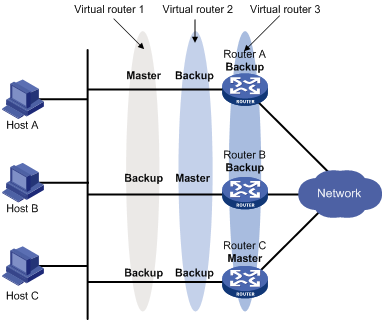
A router can be in multiple VRRP groups and have a different priority in each group.
As shown in Figure 10, the following VRRP groups are present:
· VRRP group 1—Router A is the master. Router B and Router C are the backups.
· VRRP group 2—Router B is the master. Router A and Router C are the backups.
· VRRP group 3—Router C is the master. Router A and Router B are the backups.
To implement load sharing among Router A, Router B, and Router C, perform the following tasks:
· Configure the virtual IP addresses of VRRP group 1, 2, and 3 as default gateway IP addresses for hosts on the subnet.
· Assign the highest priority to Router A, B, and C in VRRP group 1, 2, and 3, respectively.
VRRP load balancing mode
Only the FX and FE cards support the VRRP load balancing mode.
In a standard-mode VRRP group, only the master can forward packets and backups are in listening state. You can create multiple VRRP groups to share traffic, but you must configure different gateways for hosts on the subnet.
In load balancing mode, a VRRP group maps its virtual IP address to multiple virtual MAC addresses, assigning one virtual MAC address to each member router. Every router in this VRRP group can forward traffic and respond to IPv4 ARP requests from hosts. Because their virtual MAC addresses are different, traffic from hosts is distributed across the VRRP group members. Load balancing mode simplifies configuration and improves forwarding efficiency.
VRRP load balancing mode uses the same master election, preemption, and tracking mechanisms as the standard mode, and adds new mechanisms as described in the following sections.
Virtual MAC address assignment
In load balancing mode, the master assigns virtual MAC addresses to routers in the VRRP group and uses different MAC addresses to respond to ARP requests or ND requests from different hosts. The backup routers, however, do not answer ARP requests or ND requests from hosts.
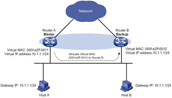
In an IPv4 network, a load balanced VRRP group works as follows:
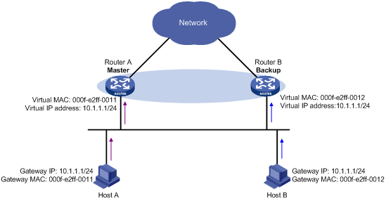
1. The master assigns virtual MAC addresses to all member routers, including itself. This example assumes that the virtual IP address of the VRRP group is 10.1.1.1/24, Router A is the master, and Router B is the backup. Router A assigns 000f-e2ff-0011 for itself and 000f-e2ff-0012 for Router B. See Figure 11.
Figure 11 Virtual MAC address assignment
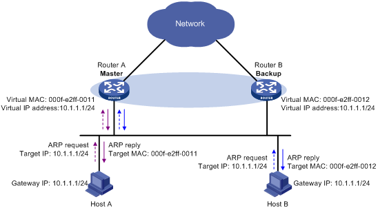
2. When an ARP request arrives, the master (Router A) selects a virtual MAC address based on the load balancing algorithm to answer the ARP request. In this example, Router A returns the virtual MAC address of itself in response to the ARP request from Host A, and returns the virtual MAC address of Router B in response to the ARP request from Host B. See Figure 12.
Figure 12 Answering ARP requests
3. Each host sends packets to the returned MAC address. As shown in Figure 13, Host A sends packets to Router A and Host B sends packets to Router B.
Figure 13 Sending packets to different routers for forwarding
Virtual forwarder
Virtual forwarder creation
Virtual MAC addresses enable traffic distribution across routers in a VRRP group. To enable routers in the VRRP group to forward packets, VFs must be created on them. Each VF is associated with a virtual MAC address in the VRRP group and forwards packets that are sent to this virtual MAC address.
VFs are created on routers in a VRRP group, as follows:
1. The master assigns virtual MAC addresses to all routers in the VRRP group. Each member router creates a VF for this MAC address and becomes the owner of this VF.
2. Each VF owner advertises its VF information to the other member routers.
3. After receiving the VF advertisement, each of the other routers creates the advertised VF.
Eventually, every member router maintains one VF for each virtual MAC address in the VRRP group.
VF weight and priority
The weight of a VF indicates the forwarding capability of a VF. A higher weight means higher forwarding capability. When the weight is lower than the lower limit of failure, the VF cannot forward packets.
The priority of a VF determines the VF state. Among the VFs created on different member routers for the same virtual MAC address, the VF with the highest priority, known as the active virtual forwarder (AVF), is in active state to forward packets. All other VFs listen to the state of the AVF and are known as the listening virtual forwarders (LVFs). VF priority is in the range of 0 to 255, where 255 is reserved for the VF owner. When the weight of a VF owner is higher than or equal to the lower limit of failure, the priority of the VF owner is 255.
The priority of a VF is calculated based on its weight.
· On the router that owns the VF, if the weight of the VF is higher than or equal to the lower limit of failure, the priority of the VF is 255.
· On a router that does not own the VF, if the weight of the VF is higher than or equal to the lower limit of failure, the priority of the VF is calculated as weight/(number of local AVFs +1).
· If the weight of the VF is lower than the lower limit of failure, the priority of the VF is 0.
VF backup
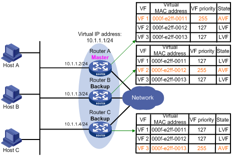
Figure 14 shows the VF table on each router in the VRRP group and how the VFs back up one another. The master, Router A, assigns virtual MAC addresses 000f-e2ff-0011, 000f-e2ff-0012, and 000f-e2ff-0013 to itself, Router B, and Router C; and each router creates VF 1, VF 2, and VF 3, respectively, for the virtual MAC addresses. The VFs for the same virtual MAC address on different routers back up one another. For example, the VF 1 instances on Router A, Router B, and Router C back up one another.
· The VF 1 instances on Router B and Router C have a priority of 255/(1 + 1), or 127. Because their priorities are lower than the priority of the VF 1 instance on Router A, they act as LVFs to listen to the state of the VF 1 instance on Router A.
· When the VF 1 instance on Router A fails, the VF 1 instances on Router B and Router C elect the one with higher priority as the new AVF to forward packets destined for virtual MAC address 000f-e2ff-0011. If the two LVFs' priorities are the same, the LVF with a greater device MAC address becomes the new AVF.
A VF always operates in preemptive mode. When an LVF finds its priority value higher than the one advertised by the AVF, the LVF declares itself as the AVF.
VF timers
When the AVF on a router fails, the new AVF on another router creates a redirect timer and a timeout timer for the failed AVF, as follows:
· Redirect timer—Before this timer expires, the master still uses the virtual MAC address corresponding to the failed AVF to respond to ARP/ND requests from hosts. The VF owner can share traffic load if the VF owner resumes normal operation within this time. When this timer expires, the master stops using the virtual MAC address corresponding to the failed AVF to respond to ARP/ND requests from hosts.
· Timeout timer—The duration after which the new AVF takes over responsibilities of the failed VF owner. Before this timer expires, all routers in the VRRP group keep the VFs that correspond to the failed AVF. The new AVF forwards packets destined for the virtual MAC address of the failed AVF. When this timer expires, all routers in the VRRP group remove the VFs that correspond to the failed AVF, including the new AVF. Packets destined for the virtual MAC address of the failed AVF are not forwarded any longer.
VF tracking
An AVF forwards packets destined for the MAC address of the AVF. If the upstream link of the AVF fails but no LVF takes over the AVF role, the hosts on the subnet that use the MAC address of the AVF as their gateway MAC address cannot access the external network.
The VF tracking function can solve this problem. You can use NQA or BFD to monitor the upstream link state of the VF owner, and establish the collaboration between the VFs and NQA or BFD through the tracking function. When the upstream link fails, the state of the track entry changes to Negative, and the weights of the VFs (including the AVF) on the router decrease by a specified value. The corresponding LVF with a higher priority on another router becomes the AVF and forwards packets.
The VF tracking function can also work on an LVF to monitor its corresponding AVF on another router. When the AVF fails, the LVF immediately takes over to ensure uninterrupted network communications.
Protocols and standards
· RFC 3768, Virtual Router Redundancy Protocol (VRRP)
· RFC 5798, Virtual Router Redundancy Protocol (VRRP) Version 3 for IPv4 and IPv6
Configuring IPv4 VRRP
IPv4 VRRP configuration task list
|
Tasks at a glance |
Remarks |
|
(Required.) Specifying an IPv4 VRRP operating mode |
N/A |
|
(Optional.) Specifying the IPv4 VRRP version |
N/A |
|
(Required.) Creating a VRRP group and assigning a virtual IP address |
N/A |
|
(Optional.) Configuring the router priority, preemptive mode, and tracking function |
N/A |
|
N/A |
|
|
(Optional.) Configuring VF tracking |
This configuration applies only to VRRP load balancing mode. |
|
(Optional.) Enabling SNMP notifications for VRRP |
N/A |
|
(Optional.) Disabling an IPv4 VRRP group |
N/A |
Specifying an IPv4 VRRP operating mode
A VRRP group can operate in either of the following modes:
· Standard mode—Only the master can forward packets.
· Load balancing mode—All members that have an AVF can forward packets.
After an IPv4 VRRP operating mode is configured on a router, all IPv4 VRRP groups on the router operate in the specified operating mode.
To specify an IPv4 VRRP operating mode:
|
Step |
Command |
Remarks |
|
1. Enter system view. |
system-view |
N/A |
|
2. Specify an IPv4 VRRP operating mode. |
·
Specify the standard mode: ·
Specify the load balancing mode: |
By default, VRRP operates in standard mode. |
Specifying the IPv4 VRRP version
The VRRP version on all routers in an IPv4 VRRP group must be the same.
To specify the version of IPv4 VRRP:
|
Step |
Command |
Remarks |
|
1. Enter system view. |
system-view |
N/A |
|
2. Enter interface view. |
interface interface-type interface-number |
N/A |
|
3. Specify the version of VRRP. |
vrrp version version-number |
By default, VRRPv3 is used. |
Creating a VRRP group and assigning a virtual IP address
A VRRP group can operate correctly after you create it and assign at least one virtual IP address to it. You can configure multiple virtual IP addresses for the VRRP group on an interface that connects to multiple subnets for router backup on different subnets.
Configuration guidelines
· The value range for VRRP group number varies by card and VRRP operating mode.
|
Cards |
VRRP operating mode |
Value range |
|
FC cards |
VRRP standard mode. NOTE: VRRP load balancing mode is not supported on FC cards. |
The valid value range is 1 to 7. |
|
FE and FX cards |
VRRP standard mode. |
In versions earlier than Release 1138P01, the valid value range is 1 to 7. In Release 1138P01 and later versions, the valid value range is 1 to 255. A device can have a maximum of 8 VRRP groups with different virtual router IDs. |
|
VRRP load balancing mode. |
The valid value range is 1 to 255. The maximum number of VRRP groups with different virtual router IDs on a device multiplied by the maximum number of VFs among all VRRP groups cannot be larger than 8. |
· When VRRP is operating in standard mode, the virtual IP address of a VRRP group can be either an unused IP address on the subnet where the VRRP group resides or the IP address of an interface on a router in the VRRP group.
· In load balancing mode, the virtual IP address of a VRRP group can be any unassigned IP address of the subnet where the VRRP group resides, rather than the IP address of any interface in the VRRP group. No IP address owner can exist in a VRRP group.
· When a router is the IP address owner in a VRRP group, do not configure the network command on the interface to use the IP address of the interface, or the virtual IP address of the VRRP group, to establish a neighbor relationship with the adjacent router. For more information about the network command, see Layer 3—IP Routing Command Reference.
· If you create an IPv4 VRRP group but do not assign any virtual IP address for it, the VRRP group stays in inactive state and does not function.
· Removal of the VRRP group on the IP address owner causes IP address collision. To avoid the collision, change the IP address of the interface on the IP address owner before you remove the VRRP group from the interface.
· The virtual IP addresses of an IPv4 VRRP group and the IP address of the downlink interface of the VRRP group must be in the same subnet. Otherwise, the hosts in the subnet cannot access external networks.
Configuration procedure
To create a VRRP group and assign a virtual IP address:
|
Step |
Command |
Remarks |
|
1. Enter system view. |
system-view |
N/A |
|
2. Enter interface view. |
interface interface-type interface-number |
N/A |
|
3. Create a VRRP group and assign a virtual IP address. |
vrrp vrid virtual-router-id virtual-ip virtual-address |
By default, no VRRP group exists. |
Configuring the router priority, preemptive mode, and tracking function
The router priority determines which router in the VRRP group serves as the master. The preemptive mode enables a backup to take over as the master when it detects that it has a higher priority than the current master. The tracking function decreases the router priority or enables the backup to take over as the master when the state of the monitored track entry transits to Negative.
Configuration guidelines
· The running priority of an IP address owner is always 255, and you do not need to configure it. An IP address owner always operates in preemptive mode.
· If you configure the vrrp vrid track priority reduced or vrrp vrid track switchover command on an IP address owner, the configuration does not take effect until the router becomes a non IP address owner.
Configuration procedure
To configure the router priority, preemptive mode, and tracking function:
|
Step |
Command |
Remarks |
|
1. Enter system view. |
system-view |
N/A |
|
2. Enter interface view. |
interface interface-type interface-number |
N/A |
|
3. Set the priority of the router in the VRRP group. |
vrrp vrid virtual-router-id priority priority-value |
The default setting is 100. |
|
4. Enable the preemptive mode for the router in a VRRP group and set the preemption delay. |
vrrp vrid virtual-router-id preempt-mode [ delay delay-value ] |
By default, the router in a VRRP group operates in preemptive mode and the preemption delay is 0 centiseconds, which means an immediate preemption. |
|
5. Associate a VRRP group with a track entry. |
By default, a VRRP group is not associated with any track entry. |
Configuring IPv4 VRRP packet attributes
Configuration guidelines
· You can configure different authentication modes and authentication keys for VRRP groups on an interface. However, members of the same VRRP group must use the same authentication mode and authentication key.
· In VRRPv2, all routers in a VRRP group must have the same VRRP advertisement interval.
· In VRRPv3, authentication mode and authentication key settings do not take effect.
· In VRRPv3, routers in an IPv4 VRRP group can have different intervals for sending VRRP advertisements. The master in the VRRP group sends VRRP advertisements at specified intervals, and carries the interval in the advertisements. After a backup receives the advertisement, it records the interval in the advertisement. If the backup does not receive a new VRRP advertisement from the master when the timer (3 x recorded interval + Skew_Time) expires, it regards the master as failed and takes over as the new master.
Configuration procedure
To configure VRRP packet attributes:
|
Step |
Command |
Remarks |
|
1. Enter system view. |
system-view |
N/A |
|
2. Enter interface view. |
interface interface-type interface-number |
N/A |
|
3. Configure the authentication mode and authentication key for an IPv4 VRRP group to send and receive VRRP packets. |
vrrp vrid virtual-router-id authentication-mode { md5 | simple } { cipher | plain } key |
By default, authentication is disabled. |
|
4. Set the interval at which the master in an IPv4 VRRP group sends VRRP advertisements. |
vrrp vrid virtual-router-id timer advertise adver-interval |
The default setting is 100 centiseconds. As a best practice to maintain system stability, set the VRRP advertisement interval to be greater than 100 centiseconds. |
|
5. Specify the source interface for receiving and sending VRRP packets. |
vrrp vrid virtual-router-id source-interface interface-type interface-number |
By default, the source interface for receiving and sending VRRP packets is not specified. The interface where the VRRP group resides sends and receives VRRP packets. |
|
6. Enable TTL check for IPv4 VRRP packets. |
vrrp check-ttl enable |
By default, TTL check for IPv4 VRRP packets is enabled. |
|
7. Return to system view. |
quit |
N/A |
|
8. Set a DCSP value for VRRP packets. |
vrrp dscp dscp-value |
The DSCP value identifies the packet priority during transmission. By default, the DCSP value for VRRP packets is 48. |
Configuring VF tracking
You can configure VF tracking in both standard mode and load balancing mode, but the function takes effect only in load balancing mode.
In load balancing mode, you can establish the collaboration between the VFs and NQA or BFD through the tracking function. When the state of the track entry transits to Negative, the weights of all VFs in the VRRP group on the router decrease by a specific value. When the state of the track entry transits to Positive or Notready, the original weight values of the VFs restore. If you configure the VF tracking function on an LVF to monitor its corresponding AVF on a specified router, the LVF can take over immediately when the status of the track entry becomes negative, to ensure uninterrupted network communications.
Configuration guidelines
· By default, the weight of a VF is 255, and its lower limit of failure is 10.
· When the weight of a VF owner is higher than or equal to the lower limit of failure, its priority is always 255 and does not change with the weight. To guarantee that an LVF can take over the VF owner as the AVF when the upstream link of the VF owner fails, the reduced weight for the VF owner must be higher than 245 so the weight of the VF owner can drop below the lower limit of failure.
Configuration procedure
To configure VF tracking:
|
Step |
Command |
Remarks |
|
1. Enter system view. |
system-view |
N/A |
|
2. Enter interface view. |
interface interface-type interface-number |
N/A |
|
3. Configure the VFs in a VRRP group to monitor a track entry. |
By default, the VF tracking function is not configured. |
Enabling SNMP notifications for VRRP
Perform this task to enable VRRP to report important events through notifications to the SNMP module. The SNMP module determines how to output the notifications according to the configured output rules. For more information about notifications, see Network Management and Monitoring Configuration Guide.
To enable SNMP notifications for VRRP:
|
Step |
Command |
Remarks |
|
1. Enter system view. |
system-view |
N/A |
|
2. Enable SNMP notifications for VRRP. |
snmp-agent trap enable vrrp [ auth-failure | new-master ] |
By default, SNMP notifications for VRRP are enabled. |
Disabling an IPv4 VRRP group
You can temporarily disable an IPv4 VRRP group. After being disabled, the VRRP group stays in initialized state, and its configurations remain unchanged. You can change the configuration of a VRRP group when the VRRP group is disabled. Your changes take effect when you enable the VRRP group again.
To disable an IPv4 VRRP group:
|
Step |
Command |
Remarks |
|
1. Enter system view. |
system-view |
N/A |
|
2. Enter interface view. |
interface interface-type interface-number |
N/A |
|
3. Disable a VRRP group. |
vrrp vrid virtual-router-id shutdown |
By default, a VRRP group is enabled. |
Displaying and maintaining IPv4 VRRP
Execute display commands in any view and the reset command in user view.
|
Task |
Command |
|
Display states of IPv4 VRRP groups. |
display vrrp [ interface interface-type interface-number [ vrid virtual-router-id ] ] [ verbose ] |
|
Display statistics for IPv4 VRRP groups. |
display vrrp statistics [ interface interface-type interface-number [ vrid virtual-router-id ] ] |
|
Clear statistics for IPv4 VRRP groups. |
reset vrrp statistics [ interface interface-type interface-number [ vrid virtual-router-id ] ] |
IPv4 VRRP configuration examples
This section provides examples of configuring IPv4 VRRP applications on switches.
Single VRRP group configuration example
This section provides an example of configuring a single VRRP group on switches.
Network requirements
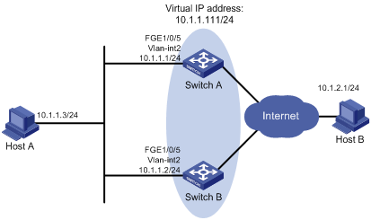
Switch A and Switch B form a VRRP group and use the virtual IP address 10.1.1.111/24 to provide gateway service for the subnet where Host A resides, as shown in Figure 15.
Switch A operates as the master to forward packets from Host A to Host B. When Switch A fails, Switch B takes over to forward packets for Host A.
Configuration procedure
1. Configure Switch A:
# Configure VLAN 2.
<SwitchA> system-view
[SwitchA] vlan 2
[SwitchA-vlan2] port fortygige 1/0/5
[SwitchA-vlan2] quit
[SwitchA] interface vlan-interface 2
[SwitchA-Vlan-interface2] ip address 10.1.1.1 255.255.255.0
# Create VRRP group 1 on VLAN-interface 2, and set its virtual IP address to 10.1.1.111.
[SwitchA-Vlan-interface2] vrrp vrid 1 virtual-ip 10.1.1.111
# Assign Switch A a higher priority than Switch B in VRRP group 1, so Switch A can become the master.
[SwitchA-Vlan-interface2] vrrp vrid 1 priority 110
# Configure Switch A to operate in preemptive mode, so it can become the master whenever it operates correctly, and set the preemption delay to 500 centiseconds to avoid frequent status switchover.
[SwitchA-Vlan-interface2] vrrp vrid 1 preempt-mode delay 500
2. Configure Switch B:
# Configure VLAN 2.
<SwitchB> system-view
[SwitchB] vlan 2
[SwitchB-Vlan2] port fortygige 1/0/5
[SwitchB-vlan2] quit
[SwitchB] interface vlan-interface 2
[SwitchB-Vlan-interface2] ip address 10.1.1.2 255.255.255.0
# Create VRRP group 1 on VLAN-interface 2, and set its virtual IP address to 10.1.1.111.
[SwitchB-Vlan-interface2] vrrp vrid 1 virtual-ip 10.1.1.111
# Set the priority of Router B to 100 in VRRP group 1.
[SwitchB-Vlan-interface2] vrrp vrid 1 priority 100
# Configure Switch B to operate in preemptive mode, and set the preemption delay to 500 centiseconds.
[SwitchB-Vlan-interface2] vrrp vrid 1 preempt-mode delay 500
3. Verify the configuration:
# Ping Host B from Host A. (Details not shown.)
# Display detailed information about VRRP group 1 on Switch A.
[SwitchA-Vlan-interface2] display vrrp verbose
IPv4 Virtual Router Information:
Running Mode : Standard
Total number of virtual routers : 1
Interface Vlan-interface2
VRID : 1 Adver Timer : 100
Admin Status : Up State : Master
Config Pri : 110 Running Pri : 110
Preempt Mode : Yes Delay Time : 500
Auth Type : None
Virtual IP : 10.1.1.111
Virtual MAC : 0000-5e00-0101
Master IP : 10.1.1.1
# Display detailed information about VRRP group 1 on Switch B.
[SwitchB-Vlan-interface2] display vrrp verbose
IPv4 Virtual Router Information:
Running Mode : Standard
Total number of virtual routers : 1
Interface Vlan-interface2
VRID : 1 Adver Timer : 100
Admin Status : Up State : Backup
Config Pri : 100 Running Pri : 100
Preempt Mode : Yes Delay Time : 500
Become Master : 401ms left
Auth Type : None
Virtual IP : 10.1.1.111
Master IP : 10.1.1.1
The output shows that Switch A is operating as the master in VRRP group 1 to forward packets from Host A to Host B.
# Disconnect the link between Host A and Switch A, and verify that Host A can still ping Host B. (Details not shown.)
# Display detailed information about VRRP group 1 on Switch B.
[SwitchB-Vlan-interface2] display vrrp verbose
IPv4 Virtual Router Information:
Running Mode : Standard
Total number of virtual routers : 1
Interface Vlan-interface2
VRID : 1 Adver Timer : 100
Admin Status : Up State : Master
Config Pri : 100 Running Pri : 100
Preempt Mode : Yes Delay Time : 500
Auth Type : None
Virtual IP : 10.1.1.111
Virtual MAC : 0000-5e00-0101
Master IP : 10.1.1.2
The output shows that when Switch A fails, Switch B takes over to forward packets from Host A to Host B.
# Recover the link between Host A and Switch A, and display detailed information about VRRP group 1 on Switch A.
[SwitchA-Vlan-interface2] display vrrp verbose
IPv4 Virtual Router Information:
Running Mode : Standard
Total number of virtual routers : 1
Interface Vlan-interface2
VRID : 1 Adver Timer : 100
Admin Status : Up State : Master
Config Pri : 110 Running Pri : 110
Preempt Mode : Yes Delay Time : 500
Auth Type : None
Virtual IP : 10.1.1.111
Virtual MAC : 0000-5e00-0101
Master IP : 10.1.1.1
The output shows that after Switch A resumes normal operation, it becomes the master to forward packets from Host A to Host B.
Multiple VRRP groups configuration example
This section provides an example of configuring multiple VRRP groups on switches.
Network requirements
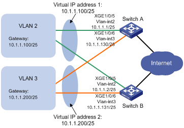
Switch A and Switch B form two VRRP groups. VRRP group 1 uses the virtual IP address 10.1.1.100/25 to provide gateway service for hosts in VLAN 2, and VRRP group 2 uses the virtual IP address 10.1.1.200/25 to provide gateway service for hosts in VLAN 3, as shown in Figure 16.
Assign a higher priority to Switch A than Switch B in VRRP group 1, but a lower priority in VRRP group 2, to distribute the traffic from VLAN 2 and VLAN 3 between the two switches. When one of the switches fails, the healthy switch provides gateway service for both VLANs.
Configuration procedure
1. Configure Switch A:
# Configure VLAN 2.
<SwitchA> system-view
[SwitchA] vlan 2
[SwitchA-vlan2] port fortygige 1/0/5
[SwitchA-vlan2] quit
[SwitchA] interface vlan-interface 2
[SwitchA-Vlan-interface2] ip address 10.1.1.1 255.255.255.128
# Create VRRP group 1, and set its virtual IP address to 10.1.1.100.
[SwitchA-Vlan-interface2] vrrp vrid 1 virtual-ip 10.1.1.100
# Assign Switch A a higher priority than Switch B in VRRP group 1, so Switch A can become the master in the group.
[SwitchA-Vlan-interface2] vrrp vrid 1 priority 110
[SwitchA-Vlan-interface2] quit
# Configure VLAN 3.
[SwitchA] vlan 3
[SwitchA-vlan3] port fortygige 1/0/6
[SwitchA-vlan3] quit
[SwitchA] interface vlan-interface 3
[SwitchA-Vlan-interface3] ip address 10.1.1.130 255.255.255.128
# Create VRRP group 2, and set its virtual IP address to 10.1.1.200.
[SwitchA-Vlan-interface3] vrrp vrid 2 virtual-ip 10.1.1.200
2. Configure Switch B:
# Configure VLAN 2.
<SwitchB> system-view
[SwitchB] vlan 2
[SwitchB-vlan2] port fortygige 1/0/5
[SwitchB-vlan2] quit
[SwitchB] interface vlan-interface 2
[SwitchB-Vlan-interface2] ip address 10.1.1.2 255.255.255.128
# Create VRRP group 1, and set its virtual IP address to 10.1.1.100.
[SwitchB-Vlan-interface2] vrrp vrid 1 virtual-ip 10.1.1.100
[SwitchB-Vlan-interface2] quit
# Configure VLAN 3.
[SwitchB] vlan 3
[SwitchB-vlan3] port fortygige 1/0/6
[SwitchB-vlan3] quit
[SwitchB] interface vlan-interface 3
[SwitchB-Vlan-interface3] ip address 10.1.1.131 255.255.255.128
# Create VRRP group 2, and set its virtual IP address to 10.1.1.200.
[SwitchB-Vlan-interface3] vrrp vrid 2 virtual-ip 10.1.1.200
# Assign Switch B a higher priority than Switch A in VRRP group 2, so Switch B can become the master in the group.
[SwitchB-Vlan-interface3] vrrp vrid 2 priority 110
3. Verify the configuration:
# Display detailed information about the VRRP groups on Switch A.
[SwitchA-Vlan-interface3] display vrrp verbose
IPv4 Virtual Router Information:
Running Mode : Standard
Total number of virtual routers : 2
Interface Vlan-interface2
VRID : 1 Adver Timer : 100
Admin Status : Up State : Master
Config Pri : 110 Running Pri : 110
Preempt Mode : Yes Delay Time : 0
Auth Type : None
Virtual IP : 10.1.1.100
Virtual MAC : 0000-5e00-0101
Master IP : 10.1.1.1
Interface Vlan-interface3
VRID : 2 Adver Timer : 100
Admin Status : Up State : Backup
Config Pri : 100 Running Pri : 100
Preempt Mode : Yes Delay Time : 0
Become Master : 203ms left
Auth Type : None
Virtual IP : 10.1.1.200
Master IP : 10.1.1.131
# Display detailed information about the VRRP groups on Switch B.
[SwitchB-Vlan-interface3] display vrrp verbose
IPv4 Virtual Router Information:
Running Mode : Standard
Total number of virtual routers : 2
Interface Vlan-interface2
VRID : 1 Adver Timer : 100
Admin Status : Up State : Backup
Config Pri : 100 Running Pri : 100
Preempt Mode : Yes Delay Time : 0
Become Master : 211ms left
Auth Type : None
Virtual IP : 10.1.1.100
Master IP : 10.1.1.1
Interface Vlan-interface3
VRID : 2 Adver Timer : 100
Admin Status : Up State : Master
Config Pri : 110 Running Pri : 110
Preempt Mode : Yes Delay Time : 0
Auth Type : None
Virtual IP : 10.1.1.200
Virtual MAC : 0000-5e00-0102
Master IP : 10.1.1.131
The output shows that Switch A is operating as the master in VRRP group 1 to forward Internet traffic for hosts that use the default gateway 10.1.1.100/25, and Switch B is operating as the master in VRRP group 2 to forward Internet traffic for hosts that use the default gateway 10.1.1.200/25.
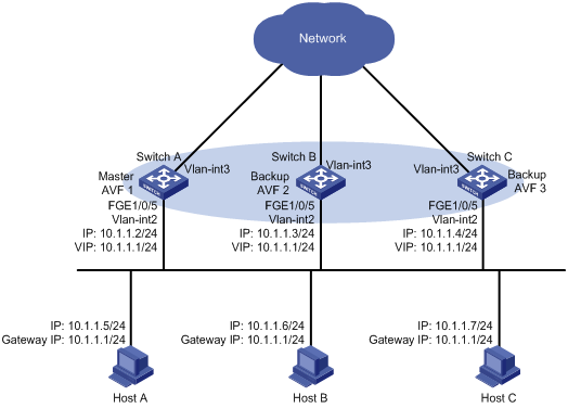
VRRP load balancing configuration example
Network requirements
Switch A, Switch B, and Switch C form a load-balanced VRRP group and use the virtual IP address 10.1.1.1/24 to provide gateway service for subnet 10.1.1.0/24, as shown in Figure 17.
Configure VFs on Switch A, Switch B, and Switch C to monitor their respective VLAN-interface 3. When the interface on any one of them fails, the weights of the VFs on the problematic switch decrease so another AVF can take over.
Configuration procedure
1. Configure Switch A:
# Configure VLAN 2.
<SwitchA> system-view
[SwitchA] vlan 2
[SwitchA-vlan2] port fortygige 1/0/5
[SwitchA-vlan2] quit
# Configure VRRP to operate in load balancing mode.
[SwitchA] vrrp mode load-balance
# Create VRRP group 1, and set its virtual IP address to 10.1.1.1.
[SwitchA] interface vlan-interface 2
[SwitchA-Vlan-interface2] ip address 10.1.1.2 24
[SwitchA-Vlan-interface2] vrrp vrid 1 virtual-ip 10.1.1.1
# Assign Switch A the highest priority in VRRP group 1, so Switch A can become the master.
[SwitchA-Vlan-interface2] vrrp vrid 1 priority 120
# Configure Switch A to operate in preemptive mode, so it can become the master whenever it operates correctly. Set the preemption delay to 500 centiseconds to avoid frequent status switchover.
[SwitchA-Vlan-interface2] vrrp vrid 1 preempt-mode delay 500
[SwitchA-Vlan-interface2] quit
# Create track entry 1 to monitor the upstream link status of VLAN-interface 3. When the upstream link fails, the track entry transits to Negative.
[SwitchA] track 1 interface vlan-interface 3
# Configure the VFs in VRRP group 1 to monitor track entry 1, and decrease their weights by 250 when the track entry transits to Negative.
[SwitchA] interface vlan-interface 2
[SwitchA-Vlan-interface2] vrrp vrid 1 track 1 weight reduced 250
2. Configure Switch B:
# Configure VLAN 2.
<SwitchB> system-view
[SwitchB] vlan 2
[SwitchB-vlan2] port fortygige 1/0/5
[SwitchB-vlan2] quit
# Configure VRRP to operate in load balancing mode.
[SwitchB] vrrp mode load-balance
# Create VRRP group 1, and set its virtual IP address to 10.1.1.1.
[SwitchB] interface vlan-interface 2
[SwitchB-Vlan-interface2] ip address 10.1.1.3 24
[SwitchB-Vlan-interface2] vrrp vrid 1 virtual-ip 10.1.1.1
# Assign Switch B a higher priority than Switch C in VRRP group 1, so Switch B can become the master when Switch A fails.
[SwitchB-Vlan-interface2] vrrp vrid 1 priority 110
# Configure Switch B to operate in preemptive mode, and set the preemption delay to 500 centiseconds.
[SwitchB-Vlan-interface2] vrrp vrid 1 preempt-mode delay 500
[SwitchB-Vlan-interface2] quit
# Create track entry 1 to monitor the upstream link status of VLAN-interface 3. When the upstream link fails, the track entry transits to Negative.
[SwitchB] track 1 interface vlan-interface 3
# Configure the VFs in VRRP group 1 to monitor track entry 1, and decrease their weights by 250 when the track entry transits to Negative.
[SwitchB] interface vlan-interface 2
[SwitchB-Vlan-interface2] vrrp vrid 1 track 1 weight reduced 250
3. Configure Switch C:
# Configure VLAN 2.
<SwitchC> system-view
[SwitchC] vlan 2
[SwitchC-vlan2] port fortygige 1/0/5
[SwitchC-vlan2] quit
# Configure VRRP to operate in load balancing mode.
[SwitchC] vrrp mode load-balance
# Create VRRP group 1, and set its virtual IP address to 10.1.1.1.
[SwitchC] interface vlan-interface 2
[SwitchC-Vlan-interface2] ip address 10.1.1.4 24
[SwitchC-Vlan-interface2] vrrp vrid 1 virtual-ip 10.1.1.1
# Configure Switch C to operate in preemptive mode, and set the preemption delay to 500 centiseconds.
[SwitchC-Vlan-interface2] vrrp vrid 1 preempt-mode delay 500
[SwitchC-Vlan-interface2] quit
# Create track entry 1 to monitor the upstream link status of VLAN-interface 3. When the upstream link fails, the traffic entry transits to Negative.
[SwitchC] track 1 interface vlan-interface 3
# Configure the VFs in VRRP group 1 to monitor track entry 1, and decrease their weights by 250 when the track entry transits to Negative.
[SwitchC] interface vlan-interface 2
[SwitchC-Vlan-interface2] vrrp vrid 1 track 1 weight reduced 250
4. Verify the configuration:
# Verify that Host A can ping the external network. (Details not shown.)
# Display detailed information about VRRP group 1 on Switch A.
[SwitchA-Vlan-interface2] display vrrp verbose
IPv4 Virtual Router Information:
Running Mode : Load Balance
Total number of virtual routers : 1
Interface Vlan-interface2
VRID : 1 Adver Timer : 100
Admin Status : Up State : Master
Config Pri : 120 Running Pri : 120
Preempt Mode : Yes Delay Time : 500
Auth Type : None
Virtual IP : 10.1.1.1
Member IP List : 10.1.1.2 (Local, Master)
10.1.1.3 (Backup)
10.1.1.4 (Backup)
Forwarder Information: 3 Forwarders 1 Active
Config Weight : 255
Running Weight : 255
Forwarder 01
State : Active
Virtual MAC : 000f-e2ff-0011 (Owner)
Owner ID : 0000-5e01-1101
Priority : 255
Active : local
Forwarder 02
State : Listening
Virtual MAC : 000f-e2ff-0012 (Learnt)
Owner ID : 0000-5e01-1103
Priority : 127
Active : 10.1.1.3
Forwarder 03
State : Listening
Virtual MAC : 000f-e2ff-0013 (Learnt)
Owner ID : 0000-5e01-1105
Priority : 127
Active : 10.1.1.4
Forwarder Weight Track Information:
Track Object : 1 State : Positive Weight Reduced : 250
# Display detailed information about VRRP group 1 on Switch B.
[SwitchB-Vlan-interface2] display vrrp verbose
IPv4 Virtual Router Information:
Running Mode : Load Balance
Total number of virtual routers : 1
Interface Vlan-interface2
VRID : 1 Adver Timer : 100
Admin Status : Up State : Backup
Config Pri : 110 Running Pri : 110
Preempt Mode : Yes Delay Time : 500
Become Master : 410ms left
Auth Type : None
Virtual IP : 10.1.1.1
Member IP List : 10.1.1.3 (Local, Backup)
10.1.1.2 (Master)
10.1.1.4 (Backup)
Forwarder Information: 3 Forwarders 1 Active
Config Weight : 255
Running Weight : 255
Forwarder 01
State : Listening
Virtual MAC : 000f-e2ff-0011 (Learnt)
Owner ID : 0000-5e01-1101
Priority : 127
Active : 10.1.1.2
Forwarder 02
State : Active
Virtual MAC : 000f-e2ff-0012 (Owner)
Owner ID : 0000-5e01-1103
Priority : 255
Active : local
Forwarder 03
State : Listening
Virtual MAC : 000f-e2ff-0013 (Learnt)
Owner ID : 0000-5e01-1105
Priority : 127
Active : 10.1.1.4
Forwarder Weight Track Information:
Track Object : 1 State : Positive Weight Reduced : 250
# Display detailed information about VRRP group 1 on Switch C.
[SwitchC-Vlan-interface2] display vrrp verbose
IPv4 Virtual Router Information:
Running Mode : Load Balance
Total number of virtual routers : 1
Interface Vlan-interface2
VRID : 1 Adver Timer : 100
Admin Status : Up State : Backup
Config Pri : 100 Running Pri : 100
Preempt Mode : Yes Delay Time : 500
Become Master : 401ms left
Auth Type : None
Virtual IP : 10.1.1.1
Member IP List : 10.1.1.4 (Local, Backup)
10.1.1.2 (Master)
10.1.1.3 (Backup)
Forwarder Information: 3 Forwarders 1 Active
Config Weight : 255
Running Weight : 255
Forwarder 01
State : Listening
Virtual MAC : 000f-e2ff-0011 (Learnt)
Owner ID : 0000-5e01-1101
Priority : 127
Active : 10.1.1.2
Forwarder 02
State : Listening
Virtual MAC : 000f-e2ff-0012 (Learnt)
Owner ID : 0000-5e01-1103
Priority : 127
Active : 10.1.1.3
Forwarder 03
State : Active
Virtual MAC : 000f-e2ff-0013 (Owner)
Owner ID : 0000-5e01-1105
Priority : 255
Active : local
Forwarder Weight Track Information:
Track Object : 1 State : Positive Weight Reduced : 250
The output shows that Switch A is the master in VRRP group 1, and each of the three switches has one AVF and two LVFs.
# Disconnect the link of VLAN-interface 3 on Switch A, and display detailed information about VRRP group 1 on Switch A.
[SwitchA-Vlan-interface2] display vrrp verbose
IPv4 Virtual Router Information:
Running Mode : Load Balance
Total number of virtual routers : 1
Interface Vlan-interface2
VRID : 1 Adver Timer : 100
Admin Status : Up State : Master
Config Pri : 120 Running Pri : 120
Preempt Mode : Yes Delay Time : 500
Auth Type : None
Virtual IP : 10.1.1.1
Member IP List : 10.1.1.2 (Local, Master)
10.1.1.3 (Backup)
10.1.1.4 (Backup)
Forwarder Information: 3 Forwarders 0 Active
Config Weight : 255
Running Weight : 5
Forwarder 01
State : Initialize
Virtual MAC : 000f-e2ff-0011 (Owner)
Owner ID : 0000-5e01-1101
Priority : 0
Active : 10.1.1.4
Forwarder 02
State : Initialize
Virtual MAC : 000f-e2ff-0012 (Learnt)
Owner ID : 0000-5e01-1103
Priority : 0
Active : 10.1.1.3
Forwarder 03
State : Initialize
Virtual MAC : 000f-e2ff-0013 (Learnt)
Owner ID : 0000-5e01-1105
Priority : 0
Active : 10.1.1.4
Forwarder Weight Track Information:
Track Object : 1 State : Negative Weight Reduced : 250
# Display detailed information about VRRP group 1 on Switch C.
[SwitchC-Vlan-interface2] display vrrp verbose
IPv4 Virtual Router Information:
Running Mode : Load Balance
Total number of virtual routers : 1
Interface Vlan-interface2
VRID : 1 Adver Timer : 100
Admin Status : Up State : Backup
Config Pri : 100 Running Pri : 100
Preempt Mode : Yes Delay Time : 500
Become Master : 401ms left
Auth Type : None
Virtual IP : 10.1.1.1
Member IP List : 10.1.1.4 (Local, Backup)
10.1.1.2 (Master)
10.1.1.3 (Backup)
Forwarder Information: 3 Forwarders 2 Active
Config Weight : 255
Running Weight : 255
Forwarder 01
State : Active
Virtual MAC : 000f-e2ff-0011 (Take Over)
Owner ID : 0000-5e01-1101
Priority : 85
Active : local
Forwarder 02
State : Listening
Virtual MAC : 000f-e2ff-0012 (Learnt)
Owner ID : 0000-5e01-1103
Priority : 85
Active : 10.1.1.3
Forwarder 03
State : Active
Virtual MAC : 000f-e2ff-0013 (Owner)
Owner ID : 0000-5e01-1105
Priority : 255
Active : local
Forwarder Weight Track Information:
Track Object : 1 State : Positive Weight Reduced : 250
The output shows that when VLAN-interface 3 on Switch A fails, the weights of the VFs on Switch A drop below the lower limit of failure. All VFs on Switch A transit to the Initialized state and cannot forward traffic. The VF for MAC address 000f-e2ff-0011 on Switch C becomes the AVF to forward traffic.
# When the timeout timer (about 1800 seconds) expires, display detailed information about VRRP group 1 on Switch C.
[SwitchC-Vlan-interface2] display vrrp verbose
IPv4 Virtual Router Information:
Running Mode : Load Balance
Total number of virtual routers : 1
Interface Vlan-interface2
VRID : 1 Adver Timer : 100
Admin Status : Up State : Backup
Config Pri : 100 Running Pri : 100
Preempt Mode : Yes Delay Time : 500
Become Master : 402ms left
Auth Type : None
Virtual IP : 10.1.1.1
Member IP List : 10.1.1.4 (Local, Backup)
10.1.1.2 (Master)
10.1.1.3 (Backup)
Forwarder Information: 2 Forwarders 1 Active
Config Weight : 255
Running Weight : 255
Forwarder 02
State : Listening
Virtual MAC : 000f-e2ff-0012 (Learnt)
Owner ID : 0000-5e01-1103
Priority : 127
Active : 10.1.1.3
Forwarder 03
State : Active
Virtual MAC : 000f-e2ff-0013 (Owner)
Owner ID : 0000-5e01-1105
Priority : 255
Active : local
Forwarder Weight Track Information:
Track Object : 1 State : Positive Weight Reduced : 250
The output shows that when the timeout timer expires, the VF for virtual MAC address 000f-e2ff-0011 is removed, and no longer forwards the packets destined for the MAC address.
# When Switch A fails, display detailed information about VRRP group 1 on Switch B.
[SwitchB-Vlan-interface2] display vrrp verbose
IPv4 Virtual Router Information:
Running Mode : Load Balance
Total number of virtual routers : 1
Interface Vlan-interface2
VRID : 1 Adver Timer : 100
Admin Status : Up State : Master
Config Pri : 110 Running Pri : 110
Preempt Mode : Yes Delay Time : 500
Auth Type : None
Virtual IP : 10.1.1.1
Member IP List : 10.1.1.3 (Local, Master)
10.1.1.4 (Backup)
Forwarder Information: 2 Forwarders 1 Active
Config Weight : 255
Running Weight : 255
Forwarder 02
State : Active
Virtual MAC : 000f-e2ff-0012 (Owner)
Owner ID : 0000-5e01-1103
Priority : 255
Active : local
Forwarder 03
State : Listening
Virtual MAC : 000f-e2ff-0013 (Learnt)
Owner ID : 0000-5e01-1105
Priority : 127
Active : 10.1.1.4
Forwarder Weight Track Information:
Track Object : 1 State : Positive Weight Reduced : 250
The output shows that when Switch A fails, Switch B becomes the master because it has a higher priority than Switch C, and the VF for virtual MAC address 000f-e2ff-0011 is removed.
Troubleshooting VRRP
An error prompt is displayed
Symptom
An error prompt "The virtual router detected a VRRP configuration error." is displayed during configuration.
Analysis
This symptom is probably caused by the following reasons:
· The VRRP advertisement interval in the packet is not the same as that for the current VRRP group (in VRRPv2 only).
· The number of virtual IP addresses in the packet is not the same as that for the current VRRP group.
· The virtual IP address list is not the same as that for the current VRRP group.
· A device in the VRRP group receives illegitimate VRRP packets. For example, the IP address owner receives a VRRP packet with the priority 255.
Solution
· Modify the configuration on routers in VRRP groups to ensure consistent configuration.
· Take fault location and anti-attack measures to eliminate potential threats.
Multiple masters appear in a VRRP group
Symptom
Multiple masters appear in a VRRP group.
Analysis
It is normal for a VRRP group to have multiple masters for a short time, and this situation requires no manual intervention.
If multiple masters coexist for a longer period, it might be because the masters cannot receive advertisements from each other, or because the received advertisements are illegitimate.
Solution
Ping between these masters, and do the following checks:
· If the ping fails, examine network connectivity.
· If the ping succeeds, check for configuration inconsistencies in the number of virtual IP addresses, virtual IP addresses, and authentication. For IPv4 VRRP, also make sure a consistent version of VRRP is configured on all routers in the VRRP group. For VRRPv2, make sure consistent VRRP advertisement interval is configured on the routers in the VRRP group.
Fast VRRP state flapping
Symptom
Fast VRRP state flapping occurs.
Analysis
The VRRP advertisement interval is set too short.
Solution
Increase the interval for sending VRRP advertisements or introduce a preemption delay.
Configuring BFD
The term "interface" in this chapter collectively refers to Layer 3 interfaces, including VLAN interfaces and Layer 3 Ethernet interfaces. You can set an Ethernet port as a Layer 3 interface by using the port link-mode route command (see Layer 2—LAN Switching Configuration Guide).
Overview
Bidirectional forwarding detection (BFD) provides a general-purpose, standard, medium- and protocol-independent fast failure detection mechanism. It can detect and monitor the connectivity of links in IP to detect communication failures quickly so that measures can be taken to ensure service continuity and enhance network availability.
BFD can uniformly and quickly detect the failures of the bidirectional forwarding paths between two devices for upper-layer protocols such as routing protocols. The hello mechanism used by upper layer protocols needs seconds to detect a link failure, while BFD can provide detection measured in milliseconds.
BFD can be used for single-hop and multi-hop detections:
· Single-hop detection—Detects the IP connectivity between two directly connected systems.
· Multi-hop detection—Detects any of the paths between two systems. These paths have multiple hops, and might overlap.
BFD session establishment
BFD does not provide any neighbor discovery mechanisms. The upper protocols notify BFD of the routers to which it needs to establish sessions.
Establishing BFD sessions
BFD sessions are established as follows:
1. A protocol sends Hello messages to discover neighbors and establish neighborships.
2. After establishing neighborships, the protocol notifies BFD of the neighbor information, including destination and source addresses.
3. BFD uses the information to establish BFD sessions.
Terminating a BFD session
When BFD detects a link failure:
1. BFD clears the neighbor session.
2. BFD notifies the protocol of the failure.
3. The protocol terminates the neighborship on the link.
4. If a backup link is available, the protocol will use it for communication.
BFD session modes and operating modes
BFD sessions use the following types of packets:
· Echo packets—Encapsulated into UDP packets with port number 3785.
· Control packets—Encapsulated into UDP packets with port number 3784 for single-hop detection or port number 4784 for multi-hop detection.
Echo packet mode
The local end of the link sends echo packets to establish BFD sessions and monitor link status. The peer end does not establish BFD sessions and only forwards the packets back to the originating end.
In echo packet mode, BFD supports only single-hop detection and the BFD session is independent of the operating mode.
Control packet mode
Both ends of the link exchange BFD control packets to monitor link status.
Before a BFD session is established, BFD has two operating modes—active and passive.
· Active mode—BFD actively sends BFD control packets regardless of whether any BFD control packet is received from the peer.
· Passive mode—BFD does not send control packets until a BFD control packet is received from the peer.
At least one end must operate in active mode for a BFD session to be established.
After a BFD session is established, both ends must operate in one of the following BFD operating modes:
· Asynchronous mode—Both endpoints periodically send BFD control packets to each other. BFD considers that the session is down if it receives no BFD control packets within a specific interval.
· Demand mode—No BFD control packets are exchanged after the session is established. When the connectivity to another system needs to be verified explicitly, a system sends several BFD control packets that have the Poll (P) bit set at the negotiated transmit interval. If no response is received within the detection interval, the session is considered down. If the connectivity is found to be up, no more BFD control packets are sent until the next command is issued.
In addition, both ends of the link can exchange BFD control packets to establish and maintain BFD sessions, and one end of the link sends echo packets to monitor link status.
Supported features
· Static routing. For more information, see Layer 3—IP Routing Configuration Guide.
· RIP. For more information, see Layer 3—IP Routing Configuration Guide.
· OSPF. For more information, see Layer 3—IP Routing Configuration Guide.
· IS-IS. For more information, see Layer 3—IP Routing Configuration Guide.
· BGP. For more information, see Layer 3—IP Routing Configuration Guide.
· PIM. For more information, see IP Multicast Configuration Guide.
· Track. For more information, see "Configuring Track."
· IP fast reroute (FRR). IP FRR is supported by OSPF, RIP, IS-IS and static routing. For more information, see Layer 3—IP Routing Configuration Guide.
Protocols and standards
· RFC 5880, Bidirectional Forwarding Detection (BFD)
· RFC 5881, Bidirectional Forwarding Detection (BFD) for IPv4 and IPv6 (Single Hop)
· RFC 5882, Generic Application of Bidirectional Forwarding Detection (BFD)
· RFC 5883, Bidirectional Forwarding Detection (BFD) for Multihop Paths
· RFC 5885, Bidirectional Forwarding Detection (BFD) for the Pseudowire Virtual Circuit Connectivity Verification (VCCV)
Configuring BFD basic functions
Before configuring BFD basic functions, configure the network layer addresses of the interfaces so that adjacent nodes are reachable to each other at the network layer.
After a BFD session is established, the two ends negotiate BFD parameters, including minimum sending interval, minimum receiving interval, initialization mode, and packet authentication, by exchanging negotiation packets. They use the negotiated parameters without affecting the session status.
Configuring echo packet mode
|
Step |
Command |
Remarks |
|
1. Enter system view. |
system-view |
N/A |
|
2. Configure the source IP address of echo packets. |
bfd echo-source-ip ip-address |
By default, no source IP address is configured for echo packets. The source IP address cannot be on the same network segment as any local interface's IP address. Otherwise, a large number of ICMP redirect packets might be sent from the peer, resulting in link congestion. |
|
3. Enter interface view. |
interface interface-type interface-number |
N/A |
|
4. (Optional.) Set the minimum interval for receiving BFD echo packets. |
bfd min-echo-receive-interval value |
The default setting is 400 milliseconds. |
|
5. (Optional.) Set the single-hop detection time multiplier. |
bfd detect-multiplier value |
The default setting is 5. |
Configuring control packet mode
To configure control packet mode for single-hop detection:
|
Step |
Command |
Remarks |
|
1. Enter system view. |
system-view |
N/A |
|
2. Specify the mode for establishing a BFD session. |
bfd session init-mode { active | passive } |
By default, active is specified. |
|
3. Enter interface view. |
interface interface-type interface-number |
N/A |
|
4. Configure the authentication mode for single-hop control packets. |
bfd authentication-mode { m-md5 | m-sha1 | md5 | sha1 | simple } key-id { cipher cipher-string | plain plain-string } |
By default, single-hop BFD packets are not authenticated. |
|
5. Enable the Demand BFD session mode. |
bfd demand enable |
By default, the BFD session is in Asynchronous mode. |
|
6. Enable the echo packet mode. |
bfd echo enable |
By default, the echo packet mode is disabled. If you enable the echo packet mode for a BFD session in which control packets are sent and the session goes up, BFD periodically sends echo packets to detect link connectivity and decrease control packet receive rate. |
|
7. Set the minimum interval for transmitting single-hop BFD control packets. |
bfd min-transmit-interval value |
The default setting is 400 milliseconds. |
|
8. Set the minimum interval for receiving single-hop BFD control packets. |
bfd min-receive-interval value |
The default setting is 400 milliseconds. |
|
9. Set the single-hop detection time multiplier. |
bfd detect-multiplier value |
The default setting is 5. |
To configure control packet mode for multi-hop detection:
|
Step |
Command |
Remarks |
|
1. Enter system view. |
system-view |
N/A |
|
2. Specify the mode for establishing a BFD session. |
bfd session init-mode { active | passive } |
By default, active is specified. |
|
3. Configure the authentication mode for multi-hop BFD control packets. |
bfd multi-hop authentication-mode { m-md5 | m-sha1 | md5 | sha1 | simple } key-id { cipher cipher-string | plain plain-string } |
By default, no authentication is performed. |
|
4. Configure the destination port number for multi-hop BFD control packets. |
bfd multi-hop destination-port port-number |
The default setting is 4784. |
|
5. Set the multi-hop detection time multiplier. |
bfd multi-hop detect-multiplier value |
The default setting is 5. |
|
6. Set the minimum interval for receiving multi-hop BFD control packets. |
bfd multi-hop min-receive-interval value |
The default setting is 400 milliseconds. |
|
7. Set the minimum interval for transmitting multi-hop BFD control packets. |
bfd multi-hop min-transmit-interval value |
The default setting is 400 milliseconds. |
Displaying and maintaining BFD
Execute the display command in any view and the reset command in user view.
|
Task |
Command |
|
Display BFD session information. |
display bfd session [ discriminator value | verbose ] |
|
Clear BFD session statistics. |
reset bfd session statistics |
Configuring Track
Overview
The Track module works between application modules and detection modules, as shown in Figure 18. It shields the differences between various detection modules from application modules.
Collaboration is enabled after you associate the Track module with a detection module and an application module. Collaboration operates as follows:
1. The detection module probes specific objects such as interface status, link status, network reachability, and network performance, and informs the Track module of detection results.
2. The Track module sends the detection results to the associated application module.
3. When notified of changes for the tracked object, the application modules can react to avoid communication interruption and network performance degradation.
Figure 18 Collaboration through the Track module
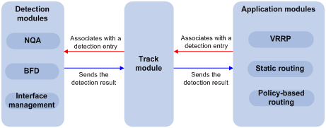
Collaboration fundamentals
The Track module collaborates with detection modules and application modules.
Collaboration between the Track module and a detection module
The detection module sends the detection result of the associated tracked object to the Track module. Depending on the result, the Track module changes the status of the track entry as follows:
· If the tracked object operates correctly, the state of the track entry is Positive. For example, the track entry state is Positive in one of the following conditions:
? The target interface is up.
? The target network is reachable.
· If the tracked object does not operate correctly, the state of the track entry is Negative. For example, the track entry state is Negative in one of the following conditions:
? The target interface is down.
? The target network is unreachable.
· If the detection result is not valid, the state of the track entry is NotReady. For example, the track entry state is NotReady if its associated NQA operation does not exist.
The following detection modules can be associated with the Track module:
· NQA.
· BFD.
· Interface management.
Collaboration between the Track module and an application module
The following application modules can be associated with the Track module:
· VRRP.
· Static routing.
· Policy-based routing.
When configuring a track entry for an application module, you can set a notification delay to avoid immediate notification of status changes. This helps prevent communication failure when route convergence is slower than the link state change notification. For example, when the master in a VRRP group detects an uplink interface failure through the Track module, the Track module notifies the master to decrease its priority. A backup with a higher priority then preempts as the new master. When the failed uplink interface recovers, the Track module immediately notifies the original master to restore its priority and forward traffic. If the uplink route has not recovered, forwarding failure will occur.
Collaboration application example
The following is an example of collaboration between NQA, Track, and static routing.
Configure a static route with next hop 192.168.0.88 on the device. If the next hop is reachable, the static route is valid. If the next hop becomes unreachable, the static route should become invalid. For this purpose, configure NQA-Track-static routing collaboration as follows:
1. Create an NQA operation to monitor the accessibility of IP address 192.168.0.88.
2. Create a track entry and associate it with the NQA operation.
? When the next hop 192.168.0.88 is reachable, the track entry is in Positive state.
? When the next hop becomes unreachable, the track entry is in Negative state.
3. Associate the track entry with the static route.
? When the track entry turns to the Positive state, the static route is valid.
? When the associated track entry turns to Negative state, the static route is invalid.
Track configuration task list
To implement the collaboration function, establish associations between the Track module and the detection modules, and between the Track module and the application modules.
To configure the Track module, perform the following tasks:
|
Tasks at a glance |
|
(Required.) Associating the Track module with a detection module: |
|
(Required.) Associating the Track module with an application module: |
Associating the Track module with a detection module
Associating Track with NQA
NQA supports multiple operation types to analyze network performance, services, and service quality. For example, an NQA operation can periodically detect whether a destination is reachable, or whether the TCP connection to a TCP server can be set up.
An NQA operation operates as follows when it is associated with a track entry:
· If the consecutive failures reach the specified threshold, the NQA module notifies the Track module that the tracked object has malfunctioned. Then the Track module sets the track entry to Negative state.
· If the specified threshold is not reached, the NQA module notifies the Track module that the tracked object is operating correctly. The Track module then sets the track entry to Positive state.
For more information about NQA, see Network Management and Monitoring Configuration Guide.
To associate Track with NQA:
|
Step |
Command |
Remarks |
|
1. Enter system view. |
system-view |
N/A |
|
2. Create a track entry, and associate it with an NQA reaction entry. |
track track-entry-number nqa entry admin-name operation-tag reaction item-number [ delay { negative negative-time | positive positive-time } * ] |
By default, no track entry is created. If the specified NQA operation or the reaction entry in the track entry does not exist, the status of the track entry is NotReady. |
Associating Track with BFD
BFD supports the control packet mode and echo packet mode. A track entry can be associated only with the echo-mode BFD session, and cannot be associated with the control-mode BFD session. For more information about BFD, see "Configuring BFD."
BFD operates as follows when it is associated with a track entry:
· If the BFD detects that the link fails, it informs the track entry of the link failure. The Track module sets the track entry to Negative state.
· If the BFD detects that the link is operating correctly, the Track module sets the track entry to Positive state.
Before you associate Track with BFD, configure the source IP address of BFD echo packets. For more information, see "Configuring BFD."
To associate Track with BFD:
|
Step |
Command |
Remarks |
|
1. Enter system view. |
system-view |
N/A |
|
2. Create a track entry, and associate it with the BFD session. |
track track-entry-number bfd echo interface interface-type interface-number remote ip remote-ip local ip local-ip [ delay { negative negative-time | positive positive-time } * ] |
By default, no track entry is created. Do not configure the virtual IP address of a VRRP group as the local or remote address of a BFD session. |
Associating Track with interface management
The interface management module monitors the link status or network-layer protocol status of the interface. The interface management module operates as follows when it is associated with a track entry:
· When the link or network-layer protocol status of the interface changes to up, the interface management module informs the Track module of the change. The Track module sets the track entry to Positive.
· When the link or network-layer protocol status of the interface changes to down, the interface management module informs the Track module of the change. The Track module sets the track entry to Negative.
To associate Track with interface management:
|
Step |
Command |
Remarks |
|
1. Enter system view. |
system-view |
N/A |
|
2. Associate Track with interface management. |
·
Create a track entry, and
associate it with the interface management module to
monitor the link status of an interface: ·
Create a track entry, and
associate it with the interface management module to
monitor the Layer 3 protocol status of an interface: |
By default, no track entry is created. |
Associating the Track module with an application module
Associating Track with VRRP
When VRRP is operating in standard mode or load balancing mode, associate the Track module with the VRRP group to implement the following actions:
· Change the priority of a router according to the status of the uplink. If a fault occurs on the uplink of the router, the VRRP group is not aware of the uplink failure. If the router is the master, hosts in the LAN cannot access the external network. To resolve this problem, configure the detection module-Track-VRRP collaboration. The detection module monitors the status of the uplink of the router and notifies the Track module of the detection result.
When the uplink fails, the detection module notifies the Track module to change the status of the monitored track entry to Negative. The priority of the master decreases by a user-specified value. A router with a higher priority in the VRRP group becomes the master.
· Monitor the master on a backup. If a fault occurs on the master, the backup operating in switchover mode will switch to the master immediately to maintain normal communication.
When VRRP is operating in load balancing mode, associate the Track module with the VRRP VF to implement the following functions:
· Change the priority of the AVF according to its uplink state. When the uplink of the AVF fails, the track entry changes to Negative state. The weight of the AVF decreases by a user-specified value. The VF with a higher priority becomes the new AVF to forward packets.
· Monitor the AVF status from the LVF. When the AVF fails, the LVF that is operating in switchover mode becomes the new AVF to ensure continuous forwarding.
When you associate Track with VRRP, follow these restrictions and guidelines:
· The vrrp vrid track priority reduced or vrrp vrid track switchover command does not take effect on an IP address owner. The command takes effect when the router does not act as the IP address owner.
An IP address owner is the router with its interface IP address used as the virtual IP address of the VRRP group.
· When the status of the track entry changes from Negative to Positive or NotReady, one of the following events occurs:
? The master router automatically restores its priority.
? The AVF automatically restores its weight.
? The failed master router becomes the master again.
? The failed AVF becomes active again.
· You can associate a nonexistent track entry with a VRRP group or VF. The association takes effect only after you create the track entry.
To associate Track with VRRP:
|
Step |
Command |
Remarks |
|
1. Enter system view. |
system-view |
N/A |
|
2. Enter interface view. |
interface interface-type interface-number |
N/A |
|
3. Associate a track entry with VRRP. |
vrrp vrid virtual-router-id track track-entry-number { forwarder-switchover member-ip ip-address | priority reduced [ priority-reduced ] | switchover | weight reduced [ weight-reduced ] } |
By default, VRRP is not associated with any track entries. |
Associating Track with static routing
A static route is a manually configured route. With a static route configured, packets to the specified destination are forwarded through the path specified by the administrator. For more information about static route configuration, see Layer 3—IP Routing Configuration Guide.
The disadvantage of using static routes is that they cannot adapt to network topology changes. Faults or topological changes in the network can make the routes unreachable, causing communication interruption.
To prevent this problem, configure another route to back up the static route. When the static route is reachable, packets are forwarded through the static route. When the static route is unreachable, packets are forwarded through the backup route.
To check the accessibility of a static route in real time, associate the Track module with the static route.
If you specify the next hop but not the output interface when configuring a static route, you can configure the static routing-Track-detection module collaboration. This collaboration enables you to check the accessibility of the static route based on the track entry state.
· If the track entry is in Positive state, the following conditions exist:
? The next hop of the static route is reachable.
? The configured static route is valid.
· If the track entry is in Negative state, the following conditions exist:
? The next hop of the static route is not reachable.
? The configured static route is invalid.
· If the track entry is in NotReady state, the following conditions exist:
? The accessibility of the next hop of the static route is unknown.
? The static route is valid.
When you associate Track with static routing, follow these restrictions and guidelines:
· You can associate a nonexistent track entry with a static route. The association takes effect only after you create the track entry.
· In static routing-Track-NQA collaboration, you must configure the same VPN instance for the NQA operation and the next hop of the static route.
· If a static route needs route recursion, the associated track entry must monitor the next hop of the recursive route instead of that of the static route. Otherwise, a valid route might be considered invalid.
To associate Track with static routing:
|
Step |
Command |
Remarks |
|
1. Enter system view. |
system-view |
N/A |
|
2. Associate the static route with a track entry to check the accessibility of the next hop. |
·
Method 2: |
By default, Track is not associated with static routing. |
Associating Track with PBR
PBR uses user-defined policies to route packets. A policy can specify parameters for packets that match specific criteria such as ACLs. The parameters include VPN instance, output interface, next hop, and default next hop. For more information about PBR, see Layer 3—IP Routing Configuration Guide.
PBR cannot detect the availability of any action taken on packets. When an action is not available, packets processed by the action might be discarded. For example, if the next hop specified for PBR fails, PBR cannot sense the failure, and continues to forward matching packets to the next hop.
This problem can be solved by associating Track with PBR. The association improves the flexibility of the PBR application and enables PBR to sense topology changes.
After you associate a track entry with an apply clause, the detection module associated with the track entry sends Track the detection result of the availability of the tracked object.
· The Positive state of the track entry shows that the object is available, and the apply clause is valid.
· The Negative state of the track entry shows that the object is not available, and the apply clause is invalid.
· The NotReady state of the track entry shows that the apply clause is valid.
the following objects can be associated with a track entry:
· Outgoing interface.
· Next hop.
· Default next hop.
Configuration prerequisites
Before you associate Track with PBR, create a policy or a policy node and configure the match criteria as well.
Configuration procedure
You can associate a nonexistent track entry with PBR. The association takes effect only after you create the track entry.
To associate Track with IPv4 PBR:
|
Step |
Command |
Remarks |
|
1. Enter system view. |
system-view |
N/A |
|
2. Create a policy or policy node and enter PBR policy node view. |
policy-based-route policy-name [ deny | permit ] node node-number |
|
|
3. Define a match criterion. |
if-match acl { acl-number | name acl-name } |
By default, no packets are filtered. |
|
4. Associate Track with PBR. |
·
Set the output interface, and associate it
with a track entry: ·
Set the next hop, and associate it with a track entry: ·
Set the default next hop, and associate it
with a track entry: |
Use at least one of the commands. |
Displaying and maintaining track entries
Execute the display command in any view.
|
Task |
Command |
|
Display information about track entries. |
display track { track-entry-number | all } |
Track configuration examples
VRRP-Track-NQA collaboration configuration example
Network requirements
As shown in Figure 19:
· Host A requires access to Host B. The default gateway of Host A is 10.1.1.10/24.
· Switch A and Switch B belong to VRRP group 1. The virtual IP address of VRRP group 1 is 10.1.1.10.
Configure VRRP-Track-NQA collaboration to monitor the uplink on the master and meet the following requirements:
· When Switch A operates correctly, packets from Host A to Host B are forwarded through Switch A.
· When NQA detects a fault on the uplink of Switch A, packets from Host A to Host B are forwarded through Switch B.
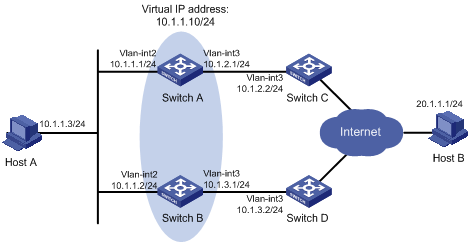
Configuration procedure
1. Configure the IP address of each VLAN interface as shown in Figure 19. (Details not shown.)
2. Configure an NQA operation on Switch A:
# Create an NQA operation with the administrator name admin and the operation tag test.
<SwitchA> system-view
[SwitchA] nqa entry admin test
# Configure the operation type as ICMP echo.
[SwitchA-nqa-admin-test] type icmp-echo
# Configure the destination address of ICMP echo requests as 10.1.2.2.
[SwitchA-nqa-admin-test-icmp-echo] destination ip 10.1.2.2
# Configure the ICMP echo operation to repeat at an interval of 100 milliseconds.
[SwitchA-nqa-admin-test-icmp-echo] frequency 100
# Configure reaction entry 1, specifying that five consecutive probe failures trigger the Track module.
[SwitchA-nqa-admin-test-icmp-echo] reaction 1 checked-element probe-fail threshold-type consecutive 5 action-type trigger-only
[SwitchA-nqa-admin-test-icmp-echo] quit
# Start the NQA operation.
[SwitchA] nqa schedule admin test start-time now lifetime forever
3. On Switch A, configure track entry 1, and associate it with reaction entry 1 of the NQA operation.
[SwitchA] track 1 nqa entry admin test reaction 1
4. Configure VRRP on Switch A:
# Specify VRRPv2 to run on VLAN-interface 2.
[SwitchA] interface vlan-interface 2
[SwitchA-Vlan-interface2] vrrp version 2
# Create VRRP group 1, and configure the virtual IP address 10.1.1.10 for the group.
[SwitchA-Vlan-interface2] vrrp vrid 1 virtual-ip 10.1.1.10
# Set the priority of Switch A in VRRP group 1 to 110.
[SwitchA-Vlan-interface2] vrrp vrid 1 priority 110
# Set the authentication mode of VRRP group 1 to simple, and the authentication key to hello.
[SwitchA-Vlan-interface2] vrrp vrid 1 authentication-mode simple hello
# Configure the master to send VRRP packets at an interval of 500 centiseconds.
[SwitchA-Vlan-interface2] vrrp vrid 1 timer advertise 500
# Configure Switch A to operate in preemptive mode, and set the preemption delay to 500 centiseconds.
[SwitchA-Vlan-interface2] vrrp vrid 1 preempt-mode timer delay 500
# Configure to monitor track entry 1, and specify the priority decrement to 30.
[SwitchA-Vlan-interface2] vrrp vrid 1 track 1 priority reduced 30
5. Configure VRRP on Switch B:
# Specify VRRPv2 to run on VLAN-interface 2.
<SwitchB> system-view
[SwitchB] interface vlan-interface 2
[SwitchB-Vlan-interface2] vrrp version 2
# Create VRRP group 1, and configure the virtual IP address 10.1.1.10 for the group.
[SwitchB-Vlan-interface2] vrrp vrid 1 virtual-ip 10.1.1.10
# Set the authentication mode of VRRP group 1 to simple, and the authentication key to hello.
[SwitchB-Vlan-interface2] vrrp vrid 1 authentication-mode simple hello
# Configure the master to send VRRP packets at an interval of 500 centiseconds.
[SwitchB-Vlan-interface2] vrrp vrid 1 timer advertise 500
# Configure Switch B to operate in preemptive mode, and set the preemption delay to 500 centiseconds.
[SwitchB-Vlan-interface2] vrrp vrid 1 preempt-mode timer delay 500
Verifying the configuration
# Ping Host B from Host A to verify that Host B is reachable. (Details not shown.)
# Display detailed information about VRRP group 1 on Switch A.
[SwitchA-Vlan-interface2] display vrrp verbose
IPv4 Virtual Router Information:
Running Mode : Standard
Total number of virtual routers : 1
Interface Vlan-interface2
VRID : 1 Adver Timer : 500
Admin Status : Up State : Master
Config Pri : 110 Running Pri : 110
Preempt Mode : Yes Delay Time : 500
Auth Type : Simple Key : ******
Virtual IP : 10.1.1.10
Virtual MAC : 0000-5e00-0101
Master IP : 10.1.1.1
VRRP Track Information:
Track Object : 1 State : Positive Pri Reduced : 30
# Display detailed information about VRRP group 1 on Switch B.
[SwitchB-Vlan-interface2] display vrrp verbose
IPv4 Virtual Router Information:
Running Mode : Standard
Total number of virtual routers : 1
Interface Vlan-interface2
VRID : 1 Adver Timer : 500
Admin Status : Up State : Backup
Config Pri : 100 Running Pri : 100
Preempt Mode : Yes Delay Time : 500
Become Master : 2200ms left
Auth Type : Simple Key : ******
Virtual IP : 10.1.1.10
Master IP : 10.1.1.1
The output shows that in VRRP group 1, Switch A is the master and Switch B is a backup. Packets from Host A to Host B are forwarded through Switch A.
# Disconnect the link between Switch A and Switch C, and verify that Host A can still ping Host B. (Details not shown.)
# Display detailed information about VRRP group 1 on Switch A.
IPv4 Virtual Router Information:
Running Mode : Standard
Total number of virtual routers : 1
Interface Vlan-interface2
VRID : 1 Adver Timer : 500
Admin Status : Up State : Backup
Config Pri : 110 Running Pri : 80
Preempt Mode : Yes Delay Time : 500
Become Master : 2200ms left
Auth Type : Simple Key : ******
Virtual IP : 10.1.1.10
Master IP : 10.1.1.2
VRRP Track Information:
Track Object : 1 State : Negative Pri Reduced : 30
# Display detailed information about VRRP group 1 on Switch B.
[SwitchB-Vlan-interface2] display vrrp verbose
IPv4 Virtual Router Information:
Running Mode : Standard
Total number of virtual routers : 1
Interface Vlan-interface2
VRID : 1 Adver Timer : 500
Admin Status : Up State : Master
Config Pri : 100 Running Pri : 100
Preempt Mode : Yes Delay Time : 500
Auth Type : Simple Key : ******
Virtual IP : 10.1.1.10
Virtual MAC : 0000-5e00-0101
Master IP : 10.1.1.2
The output shows that Switch A becomes the backup, and Switch B becomes the master. Packets from Host A to Host B are forwarded through Switch B.
Configuring BFD for a VRRP backup to monitor the master
Network requirements
As shown in Figure 20:
· Switch A and Switch B belong to VRRP group 1. The virtual IP address of VRRP group 1 is 192.168.0.10.
· The default gateway of the hosts in the LAN is 192.168.0.10.
Configure VRRP-Track-BFD collaboration to monitor the master on the backup and meet the following requirements:
· When Switch A operates correctly, the hosts in the LAN access the Internet through Switch A.
· When Switch A fails, the backup (Switch B) can detect the state change of the master through BFD and become the new master. The hosts in the LAN access the Internet through Switch B.
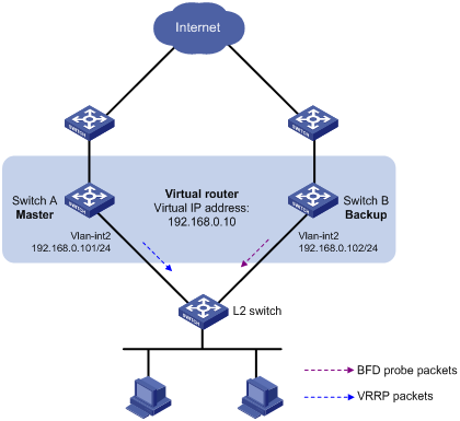
Configuration procedure
1. Configure the IP address of each VLAN interface as shown in Figure 20. (Details not shown.)
2. Configure VRRP on Switch A:
<SwitchA> system-view
[SwitchA] interface vlan-interface 2
# Create VRRP group 1, and configure the virtual IP address 192.168.0.10 for the group.
[SwitchA-Vlan-interface2] vrrp vrid 1 virtual-ip 192.168.0.10
# Set the priority of Switch A in VRRP group 1 to 110.
[SwitchA-Vlan-interface2] vrrp vrid 1 priority 110
[SwitchA-Vlan-interface2] return
3. Configure Switch B:
# Configure the source address of BFD echo packets as 10.10.10.10.
<SwitchB> system-view
[SwitchB] bfd echo-source-ip 10.10.10.10
# Create track entry 1, and associate it with the BFD session to verify the reachability of Switch A.
[SwitchB] track 1 bfd echo interface vlan-interface 2 remote ip 192.168.0.101 local ip 192.168.0.102
# Create VRRP group 1, and configure the virtual IP address 192.168.0.10 for the group.
[SwitchB] interface vlan-interface 2
[SwitchB-Vlan-interface2] vrrp vrid 1 virtual-ip 192.168.0.10
# Configure VRRP group 1 to monitor the status of track entry 1.
[SwitchB-Vlan-interface2] vrrp vrid 1 track 1 switchover
[SwitchB-Vlan-interface2] return
Verifying the configuration
# Display detailed information about VRRP group 1 on Switch A.
<SwitchA> display vrrp verbose
IPv4 Virtual Router Information:
Running Mode : Standard
Total number of virtual routers : 1
Interface Vlan-interface2
VRID : 1 Adver Timer : 100
Admin Status : Up State : Master
Config Pri : 110 Running Pri : 110
Preempt Mode : Yes Delay Time : 0
Auth Type : None
Virtual IP : 192.168.0.10
Virtual MAC : 0000-5e00-0101
Master IP : 192.168.0.101
# Display detailed information about VRRP group 1 on Switch B.
<SwitchB> display vrrp verbose
IPv4 Virtual Router Information:
Running Mode : Standard
Total number of virtual routers : 1
Interface Vlan-interface2
VRID : 1 Adver Timer : 100
Admin Status : Up State : Backup
Config Pri : 100 Running Pri : 100
Preempt Mode : Yes Delay Time : 0
Become Master : 2200ms left
Auth Type : None
Virtual IP : 192.168.0.10
Master IP : 192.168.0.101
VRRP Track Information:
Track Object : 1 State : Positive Switchover
# Display information about track entry 1 on Switch B.
<SwitchB> display track 1
Track ID: 1
State: Positive
Duration: 0 days 0 hours 0 minutes 32 seconds
Notification delay: Positive 0, Negative 0 (in seconds)
Tracked object:
BFD session mode: Echo
Outgoing interface: Vlan-interface2
VPN instance name: -
Remote IP: 192.168.0.101
Local IP: 192.168.0.102
The output shows that when the status of the track entry becomes Positive, Switch A is the master and Switch B is the backup.
# Enable VRRP state debugging and BFD event debugging on Switch B.
<SwitchB> terminal debugging
<SwitchB> terminal monitor
<SwitchB> debugging vrrp fsm
<SwitchB> debugging bfd ntfy
# When Switch A fails, the following output is displayed on Switch B.
*Dec 17 14:44:34:144 2013 SwitchB VRRP4/7/FSM:
IPv4 Vlan-interface2 | Virtual Router 1 : Backup --> Master reason: The status of the tracked object changed
# Display detailed information about the VRRP group on Switch B.
<SwitchB> display vrrp verbose
IPv4 Virtual Router Information:
Running Mode : Standard
Total number of virtual routers : 1
Interface Vlan-interface2
VRID : 1 Adver Timer : 100
Admin Status : Up State : Master
Config Pri : 100 Running Pri : 100
Preempt Mode : Yes Delay Time : 0
Auth Type : None
Virtual IP : 192.168.0.10
Virtual MAC : 0000-5e00-0101
Master IP : 192.168.0.102
VRRP Track Information:
Track Object : 1 State : Negative Switchover
The output shows that when BFD detects that Switch A fails, the Track module notifies VRRP to change the status of Switch B to master. The backup can quickly preempt as the master without waiting for a period three times the advertisement interval plus the Skew_Time.
Configuring BFD for the VRRP master to monitor the uplinks
Network requirements
As shown in Figure 21:
· Switch A and Switch B belong to VRRP group 1. The virtual IP address of VRRP group 1 is 192.168.0.10.
· The default gateway of the hosts in the LAN is 192.168.0.10.
Configure VRRP-Track-BFD collaboration to monitor the uplink on the master and meet the following requirements:
· When Switch A operates correctly, the hosts in the LAN access the Internet through Switch A.
· When Switch A detects that the uplink is down through BFD, Switch B can preempt as the master. The hosts in the LAN can access the Internet through Switch B.
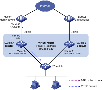
Configuration procedure
1. Configure the IP address of each VLAN interface as shown in Figure 21. (Details not shown.)
2. Configure Switch A:
# Configure the source address of BFD echo packets as 10.10.10.10.
<SwitchA> system-view
[SwitchA] bfd echo-source-ip 10.10.10.10
# Create track entry 1 for the BFD session to verify the reachability of the uplink device (1.1.1.2 ).
[SwitchA] track 1 bfd echo interface vlan-interface 3 remote ip 1.1.1.2 local ip 1.1.1.1
# Create VRRP group 1, and configure the virtual IP address of the group as 192.168.0.10.
[SwitchA] interface vlan-interface 2
[SwitchA-Vlan-interface2] vrrp vrid 1 virtual-ip 192.168.0.10
# Set the priority of Switch A in VRRP group 1 to 110.
[SwitchA-Vlan-interface2] vrrp vrid 1 priority 110
# Associate VRRP group 1 with track entry 1 and decrease the router priority by 20 when the state of track entry 1 changes to negative.
[SwitchA-Vlan-interface2] vrrp vrid 1 track 1 priority reduced 20
[SwitchA-Vlan-interface2] return
3. On Switch B, create VRRP group 1, and configure the virtual IP address of the group as 192.168.0.10.
<SwitchB> system-view
[SwitchB] interface vlan-interface 2
[SwitchB-Vlan-interface2] vrrp vrid 1 virtual-ip 192.168.0.10
[SwitchB-Vlan-interface2] return
Verifying the configuration
# Display detailed information about the VRRP group on Switch A.
<SwitchA> display vrrp verbose
IPv4 Virtual Router Information:
Running Mode : Standard
Total number of virtual routers : 1
Interface Vlan-interface2
VRID : 1 Adver Timer : 100
Admin Status : Up State : Master
Config Pri : 110 Running Pri : 110
Preempt Mode : Yes Delay Time : 0
Auth Type : None
Virtual IP : 192.168.0.10
Virtual MAC : 0000-5e00-0101
Master IP : 192.168.0.101
VRRP Track Information:
Track Object : 1 State : Positive Pri Reduced : 20
# Display information about track entry 1 on Switch A.
<SwitchA> display track 1
Track ID: 1
State: Positive
Duration: 0 days 0 hours 0 minutes 32 seconds
Notification delay: Positive 0, Negative 0 (in seconds)
Tracked object:
BFD session mode: Echo
Outgoing interface: Vlan-interface2
VPN instance name: -
Remote IP: 1.1.1.2
Local IP: 1.1.1.1
# Display detailed information about the VRRP group on Switch B.
<SwitchB> display vrrp verbose
IPv4 Virtual Router Information:
Running Mode : Standard
Total number of virtual routers : 1
Interface Vlan-interface2
VRID : 1 Adver Timer : 100
Admin Status : Up State : Backup
Config Pri : 100 Running Pri : 100
Preempt Mode : Yes Delay Time : 0
Become Master : 2200ms left
Auth Type : None
Virtual IP : 192.168.0.10
Master IP : 192.168.0.101
The output shows that when the status of track entry 1 becomes Positive, Switch A is the master, and Switch B is the backup.
# Display information about track entry 1 when the uplink of Switch A goes down.
<SwitchA> display track 1
Track ID: 1
State: Negative
Duration: 0 days 0 hours 0 minutes 32 seconds
Notification delay: Positive 0, Negative 0 (in seconds)
Tracked object:
BFD session mode: Echo
Outgoing interface: Vlan-interface2
VPN instance name: -
Remote IP: 1.1.1.2
Local IP: 1.1.1.1
# Display detailed information about VRRP group 1 on Switch A.
<SwitchA> display vrrp verbose
IPv4 Virtual Router Information:
Running Mode : Standard
Total number of virtual routers : 1
Interface Vlan-interface2
VRID : 1 Adver Timer : 100
Admin Status : Up State : Backup
Config Pri : 110 Running Pri : 90
Preempt Mode : Yes Delay Time : 0
Become Master : 2200ms left
Auth Type : None
Virtual IP : 192.168.0.10
Master IP : 192.168.0.102
VRRP Track Information:
Track Object : 1 State : Negative Pri Reduced : 20
# Display detailed information about VRRP group 1 on Switch B.
<SwitchB> display vrrp verbose
IPv4 Virtual Router Information:
Running Mode : Standard
Total number of virtual routers : 1
Interface Vlan-interface2
VRID : 1 Adver Timer : 100
Admin Status : Up State : Master
Config Pri : 100 Running Pri : 100
Preempt Mode : Yes Delay Time : 0
Auth Type : None
Virtual IP : 192.168.0.10
Virtual MAC : 0000-5e00-0101
Master IP : 192.168.0.102
The output shows that when Switch A detects that the uplink fails through BFD, it decreases its priority by 20. Switch B then preempts as the master.
Static routing-Track-BFD collaboration configuration example
Network requirements
As shown in Figure 22:
· Switch A is the default gateway of the hosts in network 20.1.1.0/24.
· Switch B is the default gateway of the hosts in network 30.1.1.0/24.
· Hosts in the two networks communicate with each other through static routes.
To ensure network availability, configure route backup and static routing-Track-BFD collaboration on Switch A and Switch B as follows:
· On Switch A, assign a higher priority to the static route to 30.1.1.0/24 with Switch B as the next hop. This route is the master route. The static route to 30.1.1.0/24 with Switch C as the next hop acts as the backup route. When the master route is unavailable, BFD can quickly detect the route failure to make the backup route take effect.
· On Switch B, assign a higher priority to the static route to 20.1.1.0/24 with Switch A as the next hop. This route is the master route. The static route to 20.1.1.0/24 with Switch C as the next hop acts as the backup route. When the master route is unavailable, BFD can quickly detect the route failure to make the backup route take effect.
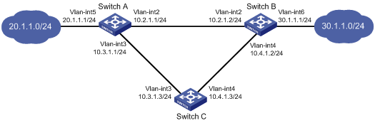
Configuration procedure
1. Configure the IP address of each VLAN interface as shown in Figure 22. (Details not shown.)
2. Configure Switch A:
# Configure a static route to 30.1.1.0/24 with the next hop 10.2.1.2 and the default priority 60, and associate this route with track entry 1.
<SwitchA> system-view
[SwitchA] ip route-static 30.1.1.0 24 10.2.1.2 track 1
# Configure a static route to 30.1.1.0/24 with the next hop 10.3.1.3 and the priority 80.
[SwitchA] ip route-static 30.1.1.0 24 10.3.1.3 preference 80
# Configure the source address of BFD echo packets as 10.10.10.10.
[SwitchA] bfd echo-source-ip 10.10.10.10
# Configure track entry 1, and associate it with the BFD session to verify the connectivity between Switch A and Switch B.
[SwitchA] track 1 bfd echo interface vlan-interface 2 remote ip 10.2.1.2 local ip 10.2.1.1
3. Configure Switch B:
# Configure a static route to 20.1.1.0/24 with the next hop 10.2.1.1 and the default priority 60, and associate this static route with track entry 1.
<SwitchB> system-view
[SwitchB] ip route-static 20.1.1.0 24 10.2.1.1 track 1
# Configure a static route to 20.1.1.0/24 with the next hop 10.4.1.3 and the priority 80.
[SwitchB] ip route-static 20.1.1.0 24 10.4.1.3 preference 80
# Configure the source address of BFD echo packets as 1.1.1.1.
[SwitchB] bfd echo-source-ip 1.1.1.1
# Configure track entry 1 that is associated with the BFD session to verify the connectivity between Switch B and Switch A.
[SwitchB] track 1 bfd echo interface vlan-interface 2 remote ip 10.2.1.1 local ip 10.2.1.2
4. Configure Switch C:
# Configure a static route to 30.1.1.0/24 with the next hop 10.4.1.2.
<SwitchC> system-view
[SwitchC] ip route-static 30.1.1.0 24 10.4.1.2
# Configure a static route to 20.1.1.0/24 with the next hop 10.3.1.1.
[SwitchB] ip route-static 20.1.1.0 24 10.3.1.1
Verifying the configuration
# Display information about the track entry on Switch A.
[SwitchA] display track all
Track ID: 1
State: Positive
Duration: 0 days 0 hours 0 minutes 32 seconds
Notification delay: Positive 0, Negative 0 (in seconds)
Tracked object:
BFD session mode: Echo
Outgoing interface: Vlan-interface2
Remote IP: 10.2.1.2
Local IP: 10.2.1.1
The output shows that the status of the track entry is Positive, indicating that the next hop 10.2.1.2 is reachable.
# Display the routing table of Switch A.
[SwitchA] display ip routing-table
Destinations : 9 Routes : 9
Destination/Mask Proto Pre Cost NextHop Interface
10.2.1.0/24 Direct 0 0 10.2.1.1 Vlan2
10.2.1.1/32 Direct 0 0 127.0.0.1 InLoop0
10.3.1.0/24 Direct 0 0 10.3.1.1 Vlan3
10.3.1.1/32 Direct 0 0 127.0.0.1 InLoop0
20.1.1.0/24 Direct 0 0 20.1.1.1 Vlan5
20.1.1.1/32 Direct 0 0 127.0.0.1 InLoop0
30.1.1.0/24 Static 60 0 10.2.1.2 Vlan2
127.0.0.0/8 Direct 0 0 127.0.0.1 InLoop0
127.0.0.1/32 Direct 0 0 127.0.0.1 InLoop0
The output shows that Switch A forwards packets to 30.1.1.0/24 through Switch B. The master static route takes effect.
# Remove the IP address of interface VLAN-interface 2 on Switch B.
<SwitchB> system-view
[SwitchB] interface vlan-interface 2
[SwitchB-Vlan-interface2] undo ip address
# Display information about the track entry on Switch A.
[SwitchA] display track all
Track ID: 1
State: Negative
Duration: 0 days 0 hours 0 minutes 32 seconds
Notification delay: Positive 0, Negative 0 (in seconds)
Tracked object:
BFD session mode: Echo
Outgoing interface: Vlan-interface2
VPN instance name: -
Remote IP: 10.2.1.2
Local IP: 10.2.1.1
The output shows that the status of the track entry is Negative, indicating that the next hop 10.2.1.2 is unreachable.
# Display the routing table of Switch A.
[SwitchA] display ip routing-table
Destinations : 9 Routes : 9
Destination/Mask Proto Pre Cost NextHop Interface
10.2.1.0/24 Direct 0 0 10.2.1.1 Vlan2
10.2.1.1/32 Direct 0 0 127.0.0.1 InLoop0
10.3.1.0/24 Direct 0 0 10.3.1.1 Vlan3
10.3.1.1/32 Direct 0 0 127.0.0.1 InLoop0
20.1.1.0/24 Direct 0 0 20.1.1.1 Vlan5
20.1.1.1/32 Direct 0 0 127.0.0.1 InLoop0
30.1.1.0/24 Static 80 0 10.3.1.3 Vlan3
127.0.0.0/8 Direct 0 0 127.0.0.1 InLoop0
127.0.0.1/32 Direct 0 0 127.0.0.1 InLoop0
The output shows that Switch A forwards packets to 30.1.1.0/24 through Switch C. The backup static route has taken effect.
# Verify that the hosts in 20.1.1.0/24 can communicate with the hosts in 30.1.1.0/24 when the master route fails.
[SwitchA] ping -a 20.1.1.1 30.1.1.1
Ping 30.1.1.1: 56 data bytes, press CTRL_C to break
Reply from 30.1.1.1: bytes=56 Sequence=1 ttl=254 time=2 ms
Reply from 30.1.1.1: bytes=56 Sequence=2 ttl=254 time=1 ms
Reply from 30.1.1.1: bytes=56 Sequence=3 ttl=254 time=1 ms
Reply from 30.1.1.1: bytes=56 Sequence=4 ttl=254 time=2 ms
Reply from 30.1.1.1: bytes=56 Sequence=5 ttl=254 time=1 ms
--- Ping statistics for 30.1.1.1 ---
5 packet(s) transmitted, 5 packet(s) received, 0.00% packet loss
round-trip min/avg/max/std-dev = 1/1/2/1 ms
# Verify that the hosts in 30.1.1.0/24 can still communicate with the hosts in 20.1.1.0/24 when the master route fails.
[SwitchB] ping -a 30.1.1.1 20.1.1.1
Ping 20.1.1.1: 56 data bytes, press CTRL_C to break
Reply from 20.1.1.1: bytes=56 Sequence=1 ttl=254 time=2 ms
Reply from 20.1.1.1: bytes=56 Sequence=2 ttl=254 time=1 ms
Reply from 20.1.1.1: bytes=56 Sequence=3 ttl=254 time=1 ms
Reply from 20.1.1.1: bytes=56 Sequence=4 ttl=254 time=1 ms
Reply from 20.1.1.1: bytes=56 Sequence=5 ttl=254 time=1 ms
--- Ping statistics for 20.1.1.1 ---
5 packet(s) transmitted, 5 packet(s) received, 0.00% packet loss
round-trip min/avg/max/std-dev = 1/1/2/1 ms
VRRP-Track-interface management collaboration configuration example
Network requirements
As shown in Figure 23:
· Host A requires access to Host B. The default gateway of Host A is 10.1.1.10/24.
· Switch A and Switch B belong to VRRP group 1. The virtual IP address of VRRP group 1 is 10.1.1.10.
Configure VRRP-Track-interface management collaboration to monitor the uplink interface on the master and meet the following requirements:
· When Switch A operates correctly, packets from Host A to Host B are forwarded through Switch A.
· When VRRP detects that a fault is on the uplink interface of Switch A through the interface management module, Switch B forwards packets from Host A to Host B.

Configuration procedure
1. Configure the IP address of each VLAN interface as shown in Figure 23. (Details not shown.)
2. Configure Switch A:
# Configure track entry 1 and associate it with the link status of the uplink interface VLAN-interface 3.
[SwitchA] track 1 interface vlan-interface 3
# Create VRRP group 1 and configure the virtual IP address 10.1.1.10 for the group.
[SwitchA] interface vlan-interface 2
[SwitchA-Vlan-interface2] vrrp vrid 1 virtual-ip 10.1.1.10
# Set the priority of Switch A in VRRP group 1 to 110.
[SwitchA-Vlan-interface2] vrrp vrid 1 priority 110
# Associate VRRP group 1 with track entry 1 and decrease the router priority by 30 when the state of track entry 1 changes to negative.
[SwitchA-Vlan-interface2] vrrp vrid 1 track 1 priority reduced 30
3. On Switch B, create VRRP group 1, and configure the virtual IP address 10.1.1.10 for the group.
<SwitchB> system-view
[SwitchB] interface vlan-interface 2
[SwitchB-Vlan-interface2] vrrp vrid 1 virtual-ip 10.1.1.10
Verifying the configuration
# Ping Host B from Host A to verify that Host B is reachable. (Details not shown.)
# Display detailed information about VRRP group 1 on Switch A.
[SwitchA-Vlan-interface2] display vrrp verbose
IPv4 Virtual Router Information:
Running Mode : Standard
Total number of virtual routers : 1
Interface Vlan-interface2
VRID : 1 Adver Timer : 100
Admin Status : Up State : Master
Config Pri : 110 Running Pri : 110
Preempt Mode : Yes Delay Time : 0
Auth Type : None
Virtual IP : 10.1.1.10
Virtual MAC : 0000-5e00-0101
Master IP : 10.1.1.1
VRRP Track Information:
Track Object : 1 State : Positive Pri Reduced : 30
# Display detailed information about VRRP group 1 on Switch B.
[SwitchB-Vlan-interface2] display vrrp verbose
IPv4 Virtual Router Information:
Running Mode : Standard
Total number of virtual routers : 1
Interface Vlan-interface2
VRID : 1 Adver Timer : 100
Admin Status : Up State : Backup
Config Pri : 100 Running Pri : 100
Preempt Mode : Yes Delay Time : 0
Become Master : 2200ms left
Auth Type : None
Virtual IP : 10.1.1.10
Master IP : 10.1.1.1
The output shows that in VRRP group 1, Switch A is the master and Switch B is a backup. Packets from Host A to Host B are forwarded through Switch A.
# Shut down the uplink interface VLAN-interface 3 on Switch A.
[SwitchA-Vlan-interface2] interface vlan-interface 3
[SwitchA-Vlan-interface3] shutdown
# Ping Host B from Host A to verify that Host B is reachable. (Details not shown.)
# Display detailed information about VRRP group 1 on Switch A.
[SwitchA-Vlan-interface3] display vrrp verbose
IPv4 Virtual Router Information:
Running Mode : Standard
Total number of virtual routers : 1
Interface Vlan-interface2
VRID : 1 Adver Timer : 100
Admin Status : Up State : Backup
Config Pri : 110 Running Pri : 80
Preempt Mode : Yes Delay Time : 0
Become Master : 2200ms left
Auth Type : None
Virtual IP : 10.1.1.10
Master IP : 10.1.1.2
VRRP Track Information:
Track Object : 1 State : Negative Pri Reduced : 30
# Display detailed information about VRRP group 1 on Switch B.
[SwitchB-Vlan-interface2] display vrrp verbose
IPv4 Virtual Router Information:
Running Mode : Standard
Total number of virtual routers : 1
Interface Vlan-interface2
VRID : 1 Adver Timer : 100
Admin Status : Up State : Master
Config Pri : 100 Running Pri : 100
Preempt Mode : Yes Delay Time : 0
Auth Type : None
Virtual IP : 10.1.1.10
Virtual MAC : 0000-5e00-0101
Master IP : 10.1.1.2
The output shows that Switch A becomes the backup, and Switch B becomes the master. Packets from Host A to Host B are forwarded through Switch B.
A
active virtual forwarder. Use AVF
advertising
high availability DLDP advertisement packet send interval, 6
high availability DLDP advertisement timer, 2
high availability VRRP advertisement interval, 17
application
high availability VRRP, 18
high availability VRRP load-sharing, 19
high availability VRRP master/backup, 18
Track application collaboration, 51
Track/application module association, 53
Track/application module collaboration, 51
Track/policy-based routing association, 56
Track/static routing association, 54
Track/VRRP association, 53
ARP
high availability VRRP virtual MAC address assignment, 20
assigning
high availability IPv4 VRRP virtual IP address, 25
high availability VRRP virtual MAC address assignment, 20
associating
Track/application module, 53
Track/BFD, 52
Track/detection modules, 52
Track/interface management, 53
Track/NQA, 52
Track/policy-based routing, 56
Track/static routing, 54
Track/VRRP, 53
attribute
high availability IPv4 VRRP packet attribute, 27
authenticating
high availability DLDP MD5 authentication, 7
high availability DLDP MD5 mode, 3
high availability DLDP non-authentication mode, 3
high availability DLDP password authentication, 7
high availability DLDP plaintext authentication, 7
high availability DLDP plaintext mode, 3
high availability DLDP simple authentication, 7
high availability VRRP MD5 authentication, 17
high availability VRRP simple authentication, 17
automatic
high availability DLDP automatic unidirectional link shutdown, 8
high availability IPv4 VRRP operating mode specification, 24
high availability VRRP virtual forwarder weight/priority, 22
B
backing up
high availability VRRP VF backup, 22
basic configuration, 47
configuration, 45
control packet mode configuration, 47
displaying, 48
echo packet mode configuration, 47
high availability VRRP tracking, 18
maintaining, 48
multi-hop detection, 45
protocols and standards, 46
session establishment, 45
session modes, 45
single-hop detection, 45
static routing-Track-BFD collaboration, 67
supported features, 46
Track BFD/VRRP backup master monitor, 61
Track BFD/VRRP master uplink monitor, 63
Track/BFD association, 52
BGP
high availability BFD supported, 46
bidirectional
forwarding detection. Use BFD
high availability DLDP port state, 2
C
collaborating
static routing-Track-BFD collaboration, 67
Track application collaboration, 51
Track BFD/VRRP backup master monitor, 61
Track BFD/VRRP master uplink monitor, 63
Track configuration, 50, 51, 57
Track/application modules, 51
Track/detection modules, 50
VRRP-Track-interface management collaboration, 70
VRRP-Track-NQA collaboration, 57
configuring
high availability BFD, 45
high availability BFD basic functions, 47
high availability BFD control packet mode, 47
high availability BFD echo packet mode, 47
high availability DLDP, 1, 5, 8
high availability DLDP authentication, 7
high availability DLDP automatic unidirectional link shutdown, 8
high availability IPv4 VRRP, 24, 29
high availability IPv4 VRRP multiple groups, 32
high availability IPv4 VRRP packet attributes, 27
high availability IPv4 VRRP router preemptive mode, 26
high availability IPv4 VRRP router priority, 26
high availability IPv4 VRRP router tracking function, 26
high availability IPv4 VRRP single group, 29
high availability VRRP, 15
high availability VRRP load-balancing mode, 35
high availability VRRP virtual forwarder tracking, 28
static routing-Track-BFD collaboration, 67
Track, 50, 51, 57
Track BFD/VRRP backup master monitor, 61
Track BFD/VRRP master uplink monitor, 63
VRRP-Track-interface management collaboration, 70
VRRP-Track-NQA collaboration, 57
confirmed DLDP neighbor state, 2
controlling
high availability BFD control packet mode, 47
creating
high availability IPv4 VRRP group, 25
D
DelayDown timer (DLDP), 2, 6
detecting
high availability BFD configuration, 45
high availability DLDP automatic unidirectional link shutdown, 8
high availability DLDP configuration, 1, 5, 8
high availability DLDP manual unidirectional link shutdown, 11
high availability DLDP multiple neighbors detection, 4
high availability DLDP single neighbor detection, 3
Track application collaboration, 51
Track configuration, 50
Track/application module collaboration, 51
Track/BFD association, 52
Track/detection module association, 52
Track/detection module collaboration, 50
Track/interface management association, 53
Track/NQA association, 52
device
high availability DLDP automatic unidirectional link shutdown, 8
high availability DLDP configuration, 1, 5, 8
high availability DLDP manual unidirectional link shutdown, 11
high availability IPv4 VRRP configuration, 29
high availability IPv4 VRRP multiple groups configuration, 32
high availability IPv4 VRRP router preemptive mode, 26
high availability IPv4 VRRP router priority, 26
high availability IPv4 VRRP router tracking, 26
high availability IPv4 VRRP single group configuration, 29
high availability VRRP group router priority, 16
high availability VRRP load-balancing mode configuration, 35
high availability VRRP router preemption modes, 16
high availability VRRP tracking, 18
link detection protocol. Use DLDP
static routing-Track-BFD collaboration, 67
Track BFD/VRRP backup master monitor, 61
Track BFD/VRRP master uplink monitor, 63
Track configuration, 57
VRRP-Track-interface management collaboration, 70
VRRP-Track-NQA collaboration, 57
disabling
high availability IPv4 VRRP group, 29
displaying
high availability BFD, 48
high availability DLDP, 7
high availability IPv4 VRRP, 29
track entries, 57
advertisement packet send interval, 6
authentication configuration, 7
authentication modes, 3
automatic unidirectional link shutdown, 8
basic concepts, 2
configuration, 1, 5, 8
configuration restrictions, 5
DelayDown timer, 6
displaying, 7
enabling, 5
how it works, 3
maintaining, 7
manual unidirectional link shutdown, 11
multiple neighbors detection, 4
neighbor states, 2
port shutdown mode, 6
port states, 2
single neighbor detection, 3
timers, 2
E
echo
high availability BFD echo packet mode, 47
high availability DLDP echo timer, 2
electing
high availability VRRP master election, 17
enabling
high availability DLDP, 5
high availability VRRP SNMP notification, 28
enhanced timer (DLDP), 2
entry timer (DLDP), 2
establishing
high availability BFD session establishment, 45
F
fast failure detection (BFD), 45
fault detection
high availability BFD basic configuration, 47
high availability BFD configuration, 45
forwarding
bidirectional detection. Use BFD
high availability VRRP virtual forwarder, 22
high availability VRRP virtual forwarder tracking, 28
FRR
high availability BFD support for IP FRR, 46
H
hardware
high availability BFD configuration, 45
high availability
BFD configuration, 45
displaying BFD, 48
displaying IPv4 VRRP, 29
displaying track entries, 57
DLDP automatic unidirectional link shutdown, 8
DLDP configuration, 1, 5, 8
DLDP manual unidirectional link shutdown, 11
IPv4 VRRP configuration, 24, 29
IPv4 VRRP group creation, 25
IPv4 VRRP group disable, 29
IPv4 VRRP multiple groups configuration, 32
IPv4 VRRP operating mode specification, 24
IPv4 VRRP packet attribute, 27
IPv4 VRRP router preemptive mode, 26
IPv4 VRRP router priority, 26
IPv4 VRRP router tracking, 26
IPv4 VRRP single group configuration, 29
IPv4 VRRP version specification, 25
IPv4 VRRP virtual IP address assignment, 25
maintaining BFD, 48
maintaining IPv4 VRRP, 29
static routing-Track-BFD collaboration, 67
Track application collaboration, 51
Track BFD/VRRP backup master monitor, 61
Track BFD/VRRP master uplink monitor, 63
Track configuration, 50, 51, 57
troubleshooting VRRP, 43
troubleshooting VRRP error prompt displayed, 43
troubleshooting VRRP fast state flapping, 43
troubleshooting VRRP multiple masters appear in group, 43
VRRP application, 18
VRRP authentication methods, 17
VRRP configuration, 15
VRRP group router priority, 16
VRRP load balancing operating mode, 20
VRRP load-balancing mode configuration, 35
VRRP operating mode, 15
VRRP protocols and standards, 24
VRRP router preemption, 16
VRRP SNMP notification, 28
VRRP standard operating mode, 16
VRRP timers, 17
VRRP tracking, 18
VRRP VF redirect timer, 23
VRRP VF timeout timer, 23
VRRP VF tracking, 24
VRRP virtual forwarder, 22
VRRP virtual forwarder tracking, 28
VRRP virtual MAC address assignment, 20
VRRP-Track-interface management collaboration, 70
VRRP-Track-NQA collaboration, 57
I
inactive
high availability DLDP port state, 2
initial DLDP port state, 2
interface management
VRRP-Track-interface management collaboration, 70
interval
high availability DLDP advertisement packet send interval, 6
IP addressing
high availability IPv4 VRRP virtual IP address assignment, 25
high availability VRRP configuration, 15
IPv4
high availability VRRP. See IPv4 VRRP
configuration, 24, 29
displaying, 29
group creation, 25
group disable, 29
load-balancing mode configuration, 35
maintaining, 29
multiple groups configuration, 32
operating mode specification, 24
packet attribute configuration, 27
router preemptive mode configuration, 26
router priority configuration, 26
router tracking function configuration, 26
single group configuration, 29
SNMP notification enable, 28
version specification, 25
virtual forwarder tracking configuration, 28
virtual IP address assignment, 25
IPv6
high availability BFD protocols and standards, 46
high availability BFD-supported static routing, 46
high availability VRRP. See IPv6 VRRP
IPv6 BGP
high availability BFD supported, 46
IPv6 IS-IS
high availability BFD supported, 46
IPv6 PIM
high availability BFD supported, 46
IS-IS
high availability BFD supported, 46
L
Layer 3
high availability BFD basic configuration, 47
high availability BFD configuration, 45
high availability BFD supported features, 46
line
high availability DLDP DelayDown line failure timer, 6
link
high availability DLDP automatic unidirectional link shutdown, 8
high availability DLDP configuration, 1, 5, 8
high availability DLDP manual unidirectional link shutdown, 11
load balancing
high availability IPv4 VRRP group creation, 25
high availability IPv4 VRRP group disable, 29
high availability IPv4 VRRP operating mode specification, 24
high availability IPv4 VRRP packet attribute, 27
high availability IPv4 VRRP router preemptive mode, 26
high availability IPv4 VRRP router priority, 26
high availability IPv4 VRRP router tracking, 26
high availability IPv4 VRRP version specification, 25
high availability IPv4 VRRP virtual IP address assignment, 25
high availability VRRP load-balancing operating mode, 15
high availability VRRP operating mode, 20
high availability VRRP virtual forwarder, 22
high availability VRRP virtual forwarder tracking, 28
high availability VRRP virtual MAC address assignment, 20
load-sharing
high availability VRRP application, 19
M
MAC addressing
high availability VRRP virtual forwarder, 22
high availability VRRP virtual MAC address assignment, 20
maintaining
high availability BFD, 48
high availability DLDP, 7
high availability IPv4 VRRP, 29
master
high availability VRRP master election, 17
high availability VRRP master/backup application, 18
high availability VRRP multiple masters appear in group, 43
MD5
high availability DLDP authentication, 7
high availability DLDP authentication mode, 3
MD5 authentication
high availability VRRP, 17
mode
high availability BFD control packet active operating mode, 45
high availability BFD control packet asynchronous operating mode, 45
high availability BFD control packet demand operating mode, 45
high availability BFD control packet mode, 45, 47
high availability BFD control packet passive operating mode, 45
high availability BFD echo packet mode, 45, 47
high availability BFD multi-hop detection, 45
high availability BFD single-hop detection, 45
high availability DLDP MD5 authentication, 3
high availability DLDP non-authentication, 3
high availability DLDP plaintext authentication, 3
high availability DLDP port shutdown auto mode, 6
high availability DLDP port shutdown manual mode, 6
high availability IPv4 VRRP router preemptive mode, 26
high availability VRRP load balancing operating mode, 20
high availability VRRP load-balancing operation, 15
high availability VRRP router non-preemptive mode, 16
high availability VRRP router preemptive mode, 16
high availability VRRP standard operating mode, 16
high availability VRRP standard operation, 15
module
static routing-Track-BFD collaboration, 67
Track application collaboration, 51
Track BFD/VRRP backup master monitor, 61
Track BFD/VRRP master uplink monitor, 63
Track configuration, 50, 51, 57
Track/application module association, 53
Track/application module collaboration, 51
Track/detection module association, 52
Track/detection module collaboration, 50
Track/interface management association, 53
Track/policy-based routing association, 56
Track/static routing association, 54
Track/VRRP association, 53
VRRP-Track-interface management collaboration, 70
VRRP-Track-NQA collaboration, 57
multi-hop
high availability BFD control packet mode, 47
high availability BFD mode, 45
multi-hop detection (BFD), 47
multiple neighbors detection (DLDP), 4
N
neighbor
high availability DLDP multiple neighbors detection, 4
high availability DLDP neighbor state, 2
high availability DLDP single neighbor detection, 3
network
high availability BFD control packet mode configuration, 47
high availability BFD echo packet mode configuration, 47
high availability DLDP authentication, 7
high availability DLDP authentication modes, 3
high availability DLDP multiple neighbors detection, 4
high availability DLDP single neighbor detection, 3
high availability IPv4 VRRP group creation, 25
high availability IPv4 VRRP group disable, 29
high availability IPv4 VRRP operating mode specification, 24
high availability IPv4 VRRP packet attribute, 27
high availability IPv4 VRRP router preemptive mode, 26
high availability IPv4 VRRP router priority, 26
high availability IPv4 VRRP router tracking, 26
high availability IPv4 VRRP version specification, 25
high availability IPv4 VRRP virtual IP address assignment, 25
high availability VRRP application, 18
high availability VRRP master election, 17
high availability VRRP timers, 17
high availability VRRP tracking, 18
Track application collaboration, 51
Track/application module association, 53
Track/BFD association, 52
Track/detection module association, 52
Track/interface management association, 53
Track/NQA association, 52
Track/policy-based routing association, 56
Track/static routing association, 54
Track/VRRP association, 53
network management
high availability BFD basic configuration, 47
high availability BFD configuration, 45
high availability DLDP automatic unidirectional link shutdown, 8
high availability DLDP configuration, 1, 5, 8
high availability DLDP manual unidirectional link shutdown, 11
high availability IPv4 VRRP configuration, 24, 29
high availability IPv4 VRRP multiple groups configuration, 32
high availability IPv4 VRRP single group configuration, 29
high availability VRRP configuration, 15
high availability VRRP load-balancing mode configuration, 35
static routing-Track-BFD collaboration, 67
Track BFD/VRRP backup master monitor, 61
Track BFD/VRRP master uplink monitor, 63
Track configuration, 50, 51, 57
VRRP-Track-interface management collaboration, 70
VRRP-Track-NQA collaboration, 57
non-authentication mode (DLDP), 3
NQA
high availability VRRP tracking, 18
Track/NQA association, 52
VRRP-Track-NQA collaboration, 57
O
OSPF
high availability BFD-supported, 46
OSPFv3
high availability BFD-supported, 46
P
packet
high availability BFD control packet mode, 47
high availability BFD echo packet mode, 47
high availability DLDP advertisement packet send interval, 6
high availability IPv4 VRRP packet attribute, 27
password
high availability DLDP authentication, 7
PIM
high availability BFD supported, 46
plaintext
high availability DLDP authentication, 7
high availability DLDP authentication mode, 3
policy-based routing
Track/application module collaboration, 51
policy-based routing (PBR)
Track/policy-based routing association, 56
port
high availability DLDP automatic unidirectional link shutdown, 8
high availability DLDP configuration, 1, 5, 8
high availability DLDP DelayDown timer, 6
high availability DLDP manual unidirectional link shutdown, 11
high availability DLDP port shutdown mode, 6
high availability DLDP port state, 2
preempting
high availability IPv4 VRRP router preemptive mode, 26
high availability VRRP non-preemptive mode, 16
high availability VRRP preemption delay timer, 17
high availability VRRP preemptive mode, 16
priority
high availability IPv4 VRRP router priority, 26
high availability VRRP group router priority, 16
high availability VRRP virtual forwarder weight/priority, 22
probe timer (DLDP), 2
procedure
assigning high availability IPv4 VRRP virtual IP address, 25
associating Track/application module, 53
associating Track/BFD, 52
associating Track/detection modules, 52
associating Track/interface management, 53
associating Track/NQA, 52
associating Track/policy-based routing, 56
associating Track/static routing, 54
associating Track/VRRP, 53
configuring high availability BFD basic functions, 47
configuring high availability BFD control packet mode (multi-hop detection), 47
configuring high availability BFD control packet mode (single-hop detection), 47
configuring high availability BFD echo packet mode, 47
configuring high availability DLDP, 5, 8
configuring high availability DLDP authentication, 7
configuring high availability DLDP automatic unidirectional link shutdown, 8
configuring high availability IPv4 VRRP, 24, 29
configuring high availability IPv4 VRRP multiple groups, 32
configuring high availability IPv4 VRRP packet attributes, 27
configuring high availability IPv4 VRRP router preemptive mode, 26
configuring high availability IPv4 VRRP router priority, 26
configuring high availability IPv4 VRRP router tracking function, 26
configuring high availability IPv4 VRRP single group, 29
configuring high availability VRRP load-balancing mode, 35
configuring high availability VRRP virtual forwarder tracking, 28
configuring static routing-Track-BFD collaboration, 67
configuring Track, 51, 57
configuring Track BFD/VRRP backup master monitor, 61
configuring Track BFD/VRRP master uplink monitor, 63
configuring VRRP-Track-interface management collaboration, 70
configuring VRRP-Track-NQA collaboration, 57
creating high availability IPv4 VRRP group, 25
disabling high availability IPv4 VRRP group, 29
displaying high availability BFD, 48
displaying high availability DLDP, 7
displaying high availability IPv4 VRRP, 29
displaying track entries, 57
enabling high availability DLDP, 5
enabling high availability VRRP SNMP notification, 28
maintaining high availability BFD, 48
maintaining high availability DLDP, 7
maintaining high availability IPv4 VRRP, 29
setting high availability DLDP advertisement packet send interval, 6
setting high availability DLDP DelayDown timer, 6
setting high availability DLDP port shutdown mode, 6
shutting down high availability DLDP unidirectional link manually, 11
specifying high availability IPv4 VRRP operating mode, 24
specifying high availability IPv4 VRRP version, 25
troubleshooting high availability VRRP error prompt displayed, 43
troubleshooting high availability VRRP multiple masters appear in group, 43
troubleshooting VRRP fast state flapping, 43
protocols and standards
high availability BFD, 46
high availability VRRP, 24
R
recoverprobe timer (DLDP), 2
restrictions
high availability DLDP configuration, 5
RIP
high availability BFD-supported, 46
router
high availability IPv4 VRRP router preemptive mode, 26
high availability IPv4 VRRP router priority, 26
high availability IPv4 VRRP router tracking, 26
high availability VRRP group priority, 16
high availability VRRP master election, 17
high availability VRRP preemption modes, 16
virtual router redundancy protocol. Use VRRP
routing
high availability DLDP automatic unidirectional link shutdown, 8
high availability DLDP configuration, 1, 5, 8
high availability DLDP manual unidirectional link shutdown, 11
high availability VRRP configuration, 15
static routing-Track-BFD collaboration, 67
Track/policy-based routing association, 56
Track/policy-based routing collaboration, 51
Track/static routing association, 54
Track/static routing collaboration, 51
S
security
high availability DLDP authentication, 7
high availability DLDP authentication modes, 3
high availability VRRP MD5 authentication, 17
high availability VRRP simple authentication, 17
session
high availability BFD control packet active operating mode, 45
high availability BFD control packet asynchronous operating mode, 45
high availability BFD control packet demand operating mode, 45
high availability BFD control packet mode, 45
high availability BFD control packet passive operating mode, 45
high availability BFD echo packet mode, 45
high availability BFD session establishment, 45
setting
high availability DLDP advertisement packet send interval, 6
high availability DLDP DelayDown timer, 6
high availability DLDP port shutdown mode, 6
shutting down
high availability DLDP automatic unidirectional link shutdown, 8
high availability DLDP port shutdown mode, 6
high availability DLDP unidirectional link manually, 11
simple authentication
high availability VRRP, 17
single neighbor detection (DLDP), 3
single-hop
high availability BFD control packet mode, 47
high availability BFD mode, 45
single-hop detection (BFD), 47
Skew-Time (VRRP), 17
specifying
high availability IPv4 VRRP operating mode, 24
high availability IPv4 VRRP version, 25
standard operating mode (VRRP), 15, 16
state
high availability DLDP neighbor state, 2
high availability DLDP port state, 2
static
high availability BFD supported static routing, 46
static routing
static routing-Track-BFD collaboration, 67
Track/application module collaboration, 51
Track/static routing association, 54
subnetting
high availability IPv4 VRRP configuration, 24, 29
high availability IPv4 VRRP multiple groups configuration, 32
high availability IPv4 VRRP single group configuration, 29
high availability VRRP configuration, 15
high availability VRRP load-balancing mode configuration, 35
switch
high availability IPv4 VRRP configuration, 29
high availability IPv4 VRRP multiple groups configuration, 32
high availability IPv4 VRRP single group configuration, 29
high availability VRRP load-balancing mode configuration, 35
T
timer
high availability DLDP advertisement, 2
high availability DLDP DelayDown, 2, 6
high availability DLDP echo, 2
high availability DLDP enhanced, 2
high availability DLDP entry, 2
high availability DLDP probe, 2
high availability DLDP recoverprobe, 2
high availability VRRP advertisement interval, 17
high availability VRRP preemption delay timer, 17
high availability VRRP Skew-Time, 17
VRRP VF redirect timer, 23
VRRP VF timeout timer, 23
Track
application collaboration, 51
application module association, 53
BFD association, 52
BFD/VRRP backup master monitor configuration, 61
BFD/VRRP master uplink monitor configuration, 63
collaboration between Track and application modules, 51
collaboration between Track and detection modules, 50
configuration, 50, 51, 57
detection module association, 52
displaying entries, 57
high availability BFD supported, 46
high availability IPv4 VRRP router tracking, 26
interface management association, 53
NQA association, 52
policy-based routing association, 56
static routing association, 54
static routing-Track-BFD collaboration configuration, 67
VRRP association, 53
VRRP-Track-interface management collaboration configuration, 70
VRRP-Track-NQA collaboration configuration, 57
tracking
high availability VRRP, 18
VRRP VF tracking, 24
traffic management
Track/application module collaboration, 51
troubleshooting
high availability VRRP, 43
high availability VRRP error prompt displayed, 43
high availability VRRP fast state flapping, 43
high availability VRRP multiple masters appear in group, 43
U
unconfirmed DLDP neighbor state, 2
unidirectional
high availability DLDP automatic unidirectional link shutdown, 8
high availability DLDP manual unidirectional link shutdown, 11
high availability DLDP port state, 2
uplink
Track BFD/VRRP master uplink monitor, 63
V
version
high availability IPv4 VRRP specification, 25
virtual
high availability IPv4 VRRP virtual IP address assignment, 25
high availability VRRP virtual forwarder, 22
high availability VRRP virtual MAC address assignment, 20
router redundancy protocol. Use VRRP
application, 18
authentication methods, 17
configuration, 15
group router priority, 16
IPv4. See IPv4 VRRP
IPv6. See IPv6 VRRP
load-sharing application, 19
master election, 17
master/backup application, 18
operating mode (load balancing), 20
operating mode (load-balancing), 15
operating mode (standard), 15, 16
protocols and standards, 24
router preemption, 16
timers, 17
Track BFD/VRRP backup master monitor, 61
Track BFD/VRRP master uplink monitor, 63
Track/application module collaboration, 51
Track/VRRP association, 53
tracking, 18
troubleshooting, 43
troubleshooting error prompt displayed, 43
troubleshooting fast state flapping, 43
troubleshooting multiple masters appear in group, 43
VF redirect timer, 23
VF timeout timer, 23
VF tracking, 24
virtual forwarder, 22
virtual forwarder backup, 22
virtual forwarder creation, 22
virtual forwarder weight/priority, 22
virtual MAC address assignment, 20
VRRP-Track-interface management collaboration, 70
VRRP-Track-NQA collaboration, 57
W
weight (VRRP virtual forwarder), 22
