- Table of Contents
| Title | Size | Download |
|---|---|---|
| 04-WLAN RRM Configuration | 150.66 KB |
Configuring data transmit rates
Configuring 802.11a/802.11b/802.11g rates
Configuring the maximum bandwidth
Configuring 802.11g protection
Configuring 802.11g protection mode
Configuring 802.11n protection
Configuring 802.11n protection mode
Displaying and maintaining WLAN RRM
Configuring band navigation parameters
Band navigation configuration examples
Band navigation configuration example
Overview
Radio signals are susceptible to surrounding interference. The causes of radio signal attenuation in different directions are very complex. Make careful plans before deploying a WLAN network. After WLAN deployment, the running parameters must still be adjusted because the radio environment is always varying due to interference from mobile obstacles, microwave ovens and so on. The running parameters adjustments are complex and require experienced personnel to implement regularly, which brings high maintenance costs.
WLAN radio resource management (RRM) is a scalable radio resource management solution. WLAN RRM delivers a real-time, intelligent, and integrated radio resource management solution. This enables a WLAN network to quickly adapt to radio environment changes and remain in a healthy state.
Configuration task list
|
Task |
Remarks |
|
Optional |
|
|
Optional |
|
|
Optional |
|
|
Optional |
|
|
Optional |
|
|
Optional |
|
|
Optional |
Configuring data transmit rates
Configuring 802.11a/802.11b/802.11g rates
|
Step |
Command |
Remarks |
|
1. Enter system view. |
system-view |
N/A |
|
2. Enter WLAN RRM view. |
wlan rrm |
N/A |
|
3. Configure rates (in Mbps) for 802.11a. |
dot11a { disabled-rate | mandatory-rate | multicast-rate | supported-rate } rate-value |
Optional. By default: · Disabled rates—None. · Mandatory rates—6, 12, and 24. · Multicast rates—Automatically selected from mandatory rates supported by all clients. · Supported rates—9, 18, 36, 48, and 54. |
|
4. Configure rates for 802.11b. |
dot11b { disabled-rate | mandatory-rate | multicast-rate | supported-rate } rate-value |
Optional. By default: · Disabled rates—None. · Mandatory rates—1 and 2. · Multicast rates—Automatically selected from mandatory rates supported by all clients. · Supported rates—5.5 and 11. |
|
5. Configure rates for 802.11g. |
dot11g { disabled-rate | mandatory-rate | multicast-rate | supported-rate } rate-value |
Optional. By default: · Disabled rates—None. · Mandatory rates—1, 2, 5.5, and 11. · Multicast rates—Automatically selected from mandatory rates supported by all clients. · Supported rates—6, 9, 12, 18, 24, 36, 48, and 54. |
Configuring 802.11n rates
Configuration of mandatory and supported 802.11n rates is achieved by specifying the maximum Modulation and Coding Scheme (MCS) index. The MCS data rate table shows relations between data rates, MCS indexes, and parameters that affect data rates. A sample MCS data rate table (20 MHz) is shown in Table 1, and a sample MCS data rate table (40 MHz) is shown in Table 2. For the whole table, see IEEE 802.11n-2009. Support for MCS indexes depends on the device model.
As shown in the two tables, MCS 0 through MCS 7 use one spatial stream, and the data rate corresponding to MCS 7 is the highest; MCS 8 through MCS 15 use two spatial streams, and the data rate corresponding to MCS 15 is the highest. MCS 16 through MCS 23 use three spatial streams, and the data rate corresponding to MCS 23 is the highest.
Table 1 MCS data rate table (20 MHz)
|
MCS index |
Number of spatial streams |
Modulation |
Data rate (Mbps) |
|
|
|
800ns GI |
400ns GI |
|
|||
|
0 |
1 |
BPSK |
6.5 |
7.2 |
|
|
1 |
1 |
QPSK |
13.0 |
14.4 |
|
|
2 |
1 |
QPSK |
19.5 |
21.7 |
|
|
3 |
1 |
16-QAM |
26.0 |
28.9 |
|
|
4 |
1 |
16-QAM |
39.0 |
43.3 |
|
|
5 |
1 |
64-QAM |
52.0 |
57.8 |
|
|
6 |
1 |
64-QAM |
58.5 |
65.0 |
|
|
7 |
1 |
64-QAM |
65.0 |
72.2 |
|
|
8 |
2 |
BPSK |
13.0 |
14.4 |
|
|
9 |
2 |
QPSK |
26.0 |
28.9 |
|
|
10 |
2 |
QPSK |
39.0 |
43.3 |
|
|
11 |
2 |
16-QAM |
52.0 |
57.8 |
|
|
12 |
2 |
16-QAM |
78.0 |
86.7 |
|
|
13 |
2 |
64-QAM |
104.0 |
115.6 |
|
|
14 |
2 |
64-QAM |
117.0 |
130.0 |
|
|
15 |
2 |
64-QAM |
130.0 |
144.4 |
|
|
16 |
3 |
BPSK |
19.5 |
21.7 |
|
|
17 |
3 |
QPSK |
39.0 |
43.3 |
|
|
18 |
3 |
QPSK |
58.5 |
65.0 |
|
|
19 |
3 |
16-QAM |
78.0 |
86.7 |
|
|
20 |
3 |
16-QAM |
117.0 |
130.0 |
|
|
21 |
3 |
64-QAM |
156.0 |
173.3 |
|
|
22 |
3 |
64-QAM |
175.5 |
195.0 |
|
|
23 |
3 |
64-QAM |
195.0 |
216.7 |
|
Table 2 MCS data rate table (40 MHz)
|
MCS index |
Number of spatial streams |
Modulation |
Data rate (Mbps) |
|
||||
|
800ns GI |
400ns GI |
|
||||||
|
0 |
1 |
BPSK |
13.5 |
15.0 |
|
|||
|
1 |
1 |
QPSK |
27.0 |
30.0 |
|
|||
|
2 |
1 |
QPSK |
40.5 |
45.0 |
|
|||
|
3 |
1 |
16-QAM |
54.0 |
60.0 |
|
|||
|
4 |
1 |
16-QAM |
81.0 |
90.0 |
|
|||
|
5 |
1 |
64-QAM |
108.0 |
120.0 |
|
|||
|
6 |
1 |
64-QAM |
121.5 |
135.0 |
|
|||
|
7 |
1 |
64-QAM |
135.0 |
150.0 |
|
|||
|
8 |
2 |
BPSK |
27.0 |
30.0 |
|
|||
|
9 |
2 |
QPSK |
54.0 |
60.0 |
|
|||
|
10 |
2 |
QPSK |
81.0 |
90.0 |
|
|||
|
11 |
2 |
16-QAM |
108.0 |
120.0 |
|
|||
|
12 |
2 |
16-QAM |
162.0 |
180.0 |
|
|||
|
13 |
2 |
64-QAM |
216.0 |
240.0 |
|
|||
|
14 |
2 |
64-QAM |
243.0 |
270.0 |
|
|||
|
15 |
2 |
64-QAM |
270.0 |
300.0 |
|
|||
|
16 |
3 |
BPSK |
40.5 |
45.0 |
||||
|
17 |
3 |
QPSK |
81.0 |
90.0 |
||||
|
18 |
3 |
QPSK |
121.5 |
135.0 |
||||
|
19 |
3 |
16-QAM |
162.0 |
180.0 |
||||
|
20 |
3 |
16-QAM |
243.0 |
270.0 |
||||
|
21 |
3 |
64-QAM |
324.0 |
360.0 |
||||
|
22 |
3 |
64-QAM |
364.5 |
405.0 |
||||
|
23 |
3 |
64-QAM |
405.0 |
450.0 |
||||
802.11 rates fall into three types: mandatory rates, supported rates, and multicast rates.
· Mandatory rates—The AP must support mandatory rates. Clients can only associate with the 802.11n AP when they support the mandatory rates.
· Supported rates—These are higher rates supported by the AP besides the mandatory rates. Supported rates allow some clients that support both mandatory and supported rates to choose higher rates when communicating with the AP.
· Multicast rates—These are rates that are supported by the AP besides the mandatory rates. Multicast rates allow clients to send multicast traffic at the multicast rates.
When you specify the maximum MCS index, you actually specify a range. For example, if you specify the maximum MCS index as 5 for mandatory rates, rates corresponding to MCS indexes 0 through 5 are configured as 802.11n mandatory rates.
To configure 802.11n rates:
|
Step |
Command |
Remarks |
|
1. Enter system view. |
system-view |
N/A |
|
2. Enter RRM view. |
wlan rrm |
N/A |
|
3. Specify the maximum MCS index for 802.11n mandatory rates. |
dot11n mandatory maximum-mcs index |
Optional. By default, no maximum MCS index is specified for 802.11n mandatory rates. If you configure the client dot11n-only command, you must specify the maximum MCS index. |
|
4. Specify the maximum MCS index for 802.11n supported rates. |
dot11n support maximum-mcs index |
Optional. By default, the maximum MCS index for 802.11n supported rates is 76. |
|
5. Specify the MCS index for 802.11n multicast rates. |
dot11n multicast-rate index |
Optional. By default, the MCS index for 802.11n multicast rates is not specified. Configure the same MCS index settings for APs using 802.11n radios in a mesh network. |
Configuring 802.11ac rates
802.11 ac uses Very High Throughput Modulation and Coding Scheme (VHT-MCS) indexes to indicate wireless data rates. A VHT-MCS is identified by a VHT-MCS index, which is represented by an integer in the range of 0 to 9. A VHT-MCS index is the mapping from VHT-MCS to a data rate.
802.11ac supports the 20 MHz, 40 MHz, and 80 MHz bandwidth modes, and supports a maximum of eight spatial streams.
Table 3, Table 4, and Table 5 show VHT-MCS parameters for the 20 MHz, 40 MHz, and 80 MHz bandwidth modes, respectively.
Table 3 VHT-MCS parameters (20 MHz, NSS=1)
|
VHT-MCS index |
Modulation |
Data rate (Mbps) |
|
|
800ns GI |
400ns GI |
||
|
0 |
BPSK |
6.5 |
7.2 |
|
1 |
QPSK |
13.0 |
14.4 |
|
2 |
QPSK |
19.5 |
21.7 |
|
3 |
16-QAM |
26.0 |
28.9 |
|
4 |
16-QAM |
39.0 |
43.3 |
|
5 |
64-QAM |
52.0 |
57.8 |
|
6 |
64-QAM |
58.5 |
65.0 |
|
7 |
64-QAM |
65.0 |
72.2 |
|
8 |
256-QAM |
78.0 |
86.7 |
|
9 |
Not valid |
||
Table 4 VHT-MCS parameters (40 MHz, NSS=1)
|
VHT-MCS index |
Modulation |
Data rate (Mbps) |
|
|
800ns GI |
400ns GI |
||
|
0 |
BPSK |
13.5 |
15.0 |
|
1 |
QPSK |
27.0 |
30.0 |
|
2 |
QPSK |
40.5 |
45.0 |
|
3 |
16-QAM |
54.0 |
60.0 |
|
4 |
16-QAM |
81.0 |
90.0 |
|
5 |
64-QAM |
108.0 |
120.0 |
|
6 |
64-QAM |
121.5 |
135.0 |
|
7 |
64-QAM |
135.0 |
150.0 |
|
8 |
256-QAM |
162.0 |
180.0 |
|
9 |
256-QAM |
180.0 |
200.0 |
Table 5 VHT-MCS parameters (80 MHz, NSS=1)
|
VHT-MCS index |
Modulation |
Data rate (Mbps) |
|
|
800ns GI |
400ns GI |
||
|
0 |
BPSK |
29.3 |
32.5 |
|
1 |
QPSK |
58.5 |
65.0 |
|
2 |
QPSK |
87.8 |
97.5 |
|
3 |
16-QAM |
117.0 |
130.0 |
|
4 |
16-QAM |
175.5 |
195.0 |
|
5 |
64-QAM |
234.0 |
260.0 |
|
6 |
64-QAM |
263.3 |
292.5 |
|
7 |
64-QAM |
292.5 |
325.0 |
|
8 |
256-QAM |
351.0 |
390.0 |
|
9 |
256-QAM |
390.0 |
433.3 |
802.11ac NSSs are classified into the following types:
· Mandatory NSSs—Mandatory NSSs for an AP. Clients can associate with an 802.11ac AP only when they support the mandatory NSSs for the AP.
· Supported NSSs—NSSs supported by an AP except for the mandatory NSSs. Supported NSSs allow a client that supports both mandatory and supported NSSs to use a higher rate to communicate with the AP.
· Multicast NSS—An AP uses a rate in the VHT-MCS data rate table for the NSS to transmit multicast frames.
When you configure 802.11ac rates, follow these restrictions and guidelines:
· When you set the maximum mandatory or supported NSS, you actually specify a range. For example, if you set the maximum mandatory NSS to 5, rates corresponding to VHT-MCS indexes for NSSs 1 through 5 are configured as 802.11ac mandatory rates.
· To configure an 802.11ac multicast rate, you need to specify both the NSS and the VHT-MCS index.
|
|
NOTE: · For the whole VHT-MCS data rate tables, see IEEE Draft P802.11ac_D5.0. · Support for VHT-MCS indexes depends on the device model. |
To configure 802.11ac rates:
|
Step |
Command |
Remarks |
|
1. Enter system view. |
system-view |
N/A |
|
2. Enter RRM view. |
wlan rrm |
N/A |
|
3. Set the maximum mandatory NSS. |
dot11ac mandatory maximum-nss number |
Optional. By default, no maximum mandatory NSS is set. If you configure the client { dot11n-only | dot11ac-only } command, you must specify the maximum mandatory NSS. |
|
4. Set the maximum supported NSS. |
dot11ac support maximum-nss number |
Optional. By default, the maximum supported NSS is 8. |
|
5. Set the multicast NSS and specify a VHT-MCS index. |
dot11ac multicast-rate nss number vht-mcs index |
Optional. By default, no multicast NSS is set. |
Configuring channel exclusion
To avoid selecting improper channels, you can exclude specific channels from automatic channel selection. The excluded channels will not be available for initial automatic channel selection. This feature does not affect WIDS.
Follow these guidelines when you configure channel exclusion:
· The channel exclusion list is not restricted by the country code. You can add channels not supported by the country code to the list, and changing the country code does not change the channel list. The device will select an available channel from the channels supported by the country code and not in the channel exclusion list. When you configure this feature, do not add all channels supported by the country code to the channel exclusion list.
· If you use the dot11a/dot11bg exclude-channel command to add an automatically selected channel into the channel exclusion list, the AC disables the radio, enables the radio, and then selects an available channel from the channels supported by the country code and not in the channel exclusion list.
· For 40 MHz 802.11n radios, 80 MHz 802.11ac radios, and 40 MHz 802.11ac radios, if you add an automatically selected primary channel to the channel exclusion list, the AC will select another available primary channel. If you add a secondary channel into the channel exclusion list in this case, the AC will select another secondary channel. If the AC cannot find an available primary channel or secondary channel, no channels will be available for the wireless services.
To configure channel exclusion:
|
Step |
Command |
Remarks |
|
1. Enter system view. |
system-view |
N/A |
|
2. Enter WLAN RRM view. |
wlan rrm |
N/A |
|
3. Configure channel exclusion. |
· dot11a exclude-channel channel-list · dot11bg exclude-channel channel-list |
Optional. By default, no channel exists in the channel exclusion list. |
Configuring the maximum bandwidth
The configured maximum bandwidth is used by the load balancing and intelligent bandwidth assurance function. For more information about intelligent bandwidth assurance, see Configuring WLAN QoS. To apply the configured maximum bandwidth on a radio, you must disable and then enable it.
|
Step |
Command |
Remarks |
|
1. Enter system view. |
system-view |
N/A |
|
2. Enter WLAN RRM view. |
wlan rrm |
N/A |
|
3. Configure the maximum bandwidth. |
·
802.11a: ·
802.11b: ·
802.11g: ·
802.11n: |
By default: · The maximum bandwidth for 802.11a is 30000 kbps. · The maximum bandwidth for 802.11b is 7000 kbps. · The maximum bandwidth for 802.11g is 30000 kbps. · The maximum bandwidth for 802.11n is 250000 kbps. Configure the maximum bandwidth close to and smaller than the upper limit of the actual traffic. |
Configuring 802.11g protection
Enabling 802.11g protection
When both 802.11b and 802.11g clients access a WLAN network, their access rates are degraded because they adopt different modulation modes. To enable them to operate properly, enable 802.11g protection for an 802.11g AP to send RTS/CTS or CTS-to-self packets (the destination of the CTS packets is the device that sends them) so 802.11b APs defer access to the medium.
The following cases require 802.11g protection to be enabled on an 802.11g AP.
· An 802.11b client associates with the 802.11g or 802.11gn AP. In this case, 802.11g protection is always enabled without manual intervention.
· The 802.11g or 802.11gn AP detects an overlapping 802.11b BSS or some 802.11b packets that are not destined to it. To enable 802.11g protection, issue the dot11g protection enable command.
To enable 802.11g protection:
|
Step |
Command |
Remarks |
|
1. Enter system view. |
system-view |
N/A |
|
2. Enter WLAN RRM view. |
wlan rrm |
N/A |
|
3. Enable 802.11g protection. |
dot11g protection enable |
Optional. By default, 802.11g protection is disabled. Enabling 802.11g protection reduces network performance. |
Configuring 802.11g protection mode
802.11g protection modes include RTS/CTS and CTS-to-self.
· RTS/CTS—An AP sends an RTS packet before sending data to a client. After receiving the RTS packet, all the devices within the coverage of the AP do not send data within the specified time. Upon receiving the RTS packet, the client sends a CTS packet. This ensures that all the devices within the coverage of the client do not send data within the specified time.
· CTS-to-Self—An AP uses its IP address to send a CTS packet before it sends data to a client. This ensures that all the devices within the coverage of the AP do not send data within the specified time.
To configure the 802.11g protection mode:
|
Step |
Command |
Remarks |
|
1. Enter system view. |
system-view |
N/A |
|
2. Enter WLAN RRM view. |
wlan rrm |
N/A |
|
3. Configure the 802.11g protection mode. |
dot11g protection-mode { cts-to-self | rts-cts } |
Optional. By default, the 802.11g protection mode is CTS-to-Self. |
Configuring 802.11n protection
Enabling 802.11n protection
When both 802.11n and non 802.11n clients access a WLAN network, interference easily occurs. The access rate is degraded significantly because they adopt different modulation modes. To enable both 802.11n and non-802.11n clients to operate properly, enable 802.11n protection for an 802.11n device to send RTS/CTS or CTS-to-self (the destination of the CTS packets is the device that sends them) packets to non-802.11n devices, which then defer access to the medium.
The following cases require 802.11n protection to be enabled an 802.11n AP.
· A non-802.11n client associates with the 802.11n AP. In this case, 802.11g protection is always enabled without manual intervention.
· The 802.11n AP detects a non-802.11n BSS or some 802.11n packets that are not destined to it. To enable 802.11n protection, issue the dot11g protection enable command.
To enable 802.11n protection:
|
Step |
Command |
Remarks |
|
1. Enter system view. |
system-view |
N/A |
|
2. Enter WLAN RRM view. |
wlan rrm |
N/A |
|
3. Enable 802.11n protection. |
dot11n protection enable |
Optional. By default, 802.11n protection is disabled. Enabling 802.11n protection reduces network performance. |
Configuring 802.11n protection mode
802.11n protection modes include RTS/CTS and CTS-to-self.
· RTS/CTS—An AP sends an RTS packet before sending data to a client. After receiving the RTS packet, all the devices within the coverage of the AP do not send data within the specified time. Upon receiving the RTS packet, the client sends a CTS packet. This ensures that all the devices within the coverage of the client do not send data within the specified time.
· CTS-to-Self—An AP uses its IP address to send a CTS packet before it sends data to a client. This ensures that all the devices within the coverage of the AP do not send data within the specified time.
To configure the 802.11n protection mode:
|
Step |
Command |
Remarks |
|
1. Enter system view. |
system-view |
N/A |
|
2. Enter WLAN RRM view. |
wlan rrm |
N/A |
|
3. Configure the 802.11n protection mode. |
dot11n protection-mode { cts-to-self | rts-cts } |
Optional. By default, the 802.11n protection mode is CTS-to-Self. |
Configuring scan parameters
The scan type and scan report-interval commands apply to WLAN IDS detection.
The autochannel-set avoid-dot11h command applies to all types of channel scanning.
To configure scan parameters:
|
Step |
Command |
Remarks |
|
1. Enter system view. |
system-view |
N/A |
|
2. Enter WLAN RRM view. |
wlan rrm |
N/A |
|
3. Set the scan type. |
scan type { active | passive } |
Optional. By default, the scan type is passive. |
|
4. Set the scan report interval. |
scan report-interval seconds |
Optional. By default, the scan report interval is 10 seconds. |
|
5. Configure only non-dot11h channels to be scanned. |
autochannel-set avoid-dot11h |
Optional. By default, the default setting of the command depends on the scan channel command. |
Configuring power constraint
To configure power constraint:
|
Step |
Command |
Remarks |
|
1. Enter system view. |
system-view |
N/A |
|
2. Enter WLAN RRM view. |
wlan rrm |
N/A |
|
3. Enable spectrum management for 802.11a, 802.11an, and 802.11ac radios. |
spectrum-management enable |
By default, spectrum management is disabled. |
|
4. Configure the power constraint for all 802.11a, 802.11an, and 802.11ac radios. |
power-constraint power-constraint |
The default power constraint is 0 dBm. |
Displaying and maintaining WLAN RRM
|
Task |
Command |
Remarks |
|
Display WLAN RRM information. |
display wlan rrm [ | { begin | exclude | include } regular-expression ] |
Available in any view. |
Configuring band navigation
Band navigation enables APs to prefer accepting dual-band (2.4 GHz and 5 GHz) clients on their 5 GHz radio because the 2.4 GHz band is often congested, increasing overall network performance.
When band navigation is enabled, the AP directs clients to its 2.4 GHz or 5 GHz radio by following these principles:
· The AP associates to a 2.4 GHz client on its 2.4 GHz radio after rejecting it several times.
· The AP directs a dual-band client to its 5 GHz radio.
· The AP associates to a 5 GHz- client on its 5 GHz radio.
The AP checks the RSSI of a dual-band client before directing the client to the 5 GHz radio. If the RSSI is lower than the value specified by the command band-navigation rssi-threshold, the AP does not direct the client to the 5 GHz band.
If the number of clients on the 5 GHz radio has reached the upper limit, and the gap between the number of clients on the 5 GHz radio and that on the 2.4 GHz radio has reached the upper limit (the two thresholds are specified by the command band-navigation balance session session [ gap gap ]), the AP denies the client’s association to the 5 GHz radio, and allows new clients to associate to the 2.4 GHz radio. If a client has been denied more than the maximum times on the 5 GHz radio (specified by the command band-navigation balance access-denial), the AP considers that the client is unable to associate to any other AP, and allows the 5 GHz radio to accept the client.
Configuration guidelines
Follow these guidelines when you configure band navigation:
· When band navigation is enabled, the client association efficiency is affected, so this feature is not recommended in a scenario where most clients use 2.4 GHz.
· Band navigation is not recommended in a delay-sensitive network.
Configuration prerequisites
To enable band navigation to operate properly, make sure of the following:
· The fast association function is disabled. By default, the fast association function is disabled. For more information about fast association, see "Configuring WLAN services."
· The SSID is bound to the 2.4 GHz and 5 GHz radios of the AP.
Enabling band navigation
|
Step |
Command |
Remarks |
|
1. Enter system view. |
system-view |
N/A |
|
2. Enter RRM view. |
wlan rrm |
N/A |
|
3. Enable band navigation. |
band-navigation enable |
By default, band navigation is disabled. |
Configuring band navigation parameters
|
Step |
Command |
Remarks |
|
1. Enter system view. |
system-view |
N/A |
|
2. Enter RRM view. |
wlan rrm |
N/A |
|
3. Configure load balancing session threshold and session gap. |
band-navigation balance session session [ gap gap ] |
Optional. By default, load balancing for band navigation is disabled. |
|
4. Configure the maximum denial count of association requests sent by a 5 GHz- client. |
band-navigation balance access-denial access-denial |
Optional. By default, an AP does not reject 5 GHz- clients. |
|
5. Configure the client RSSI threshold. |
band-navigation rssi-threshold rssi-threshold |
Optional. The default RSSI threshold is 15. |
|
6. Configure the client information aging time. |
band-navigation aging-time aging-time |
Optional. The default aging time is 180 seconds. The AP records the client information when a client tries to associate to it. If the AP receives the probe request or association request sent by the client before the aging time expires, the AP refreshes the client information and restarts the aging timer. If not, the AP removes the client information, and does not count the client during band navigation. |
Band navigation configuration examples
Band navigation configuration example
Network requirements
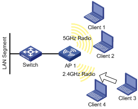
As shown in Figure 1, Client 1 through Client 4 try to associate to AP 1, and the two radios of AP 1 operate at 5 GHz and 2.4 GHz respectively. Client 1, Client 2, and Client 3 are dual-band clients, and Client 4 is a single-band (2.4 GHz) client. Configure band navigation to direct clients to different radios of the AP.
Configuration procedure
# Enable band navigation on the AP.
<AP> system-view
[AP] wlan rrm
[AP-wlan-rrm] band-navigation enable
[AP-wlan-rrm] quit
# Create a WLAN-ESS interface.
<AP> system-view
[AP] interface wlan-bss 1
[AP-WLAN-BSS1] quit
[AP] interface wlan-bss 2
[AP-WLAN-BSS2] quit
# Create service template 1 of clear type, and configure its SSID as band-navigation.
[AP] wlan service-template 1 clear
[AP-wlan-st-1] ssid band-navigation
# Disable fast association (Optional. By default, fast association is disabled.)
[AP-wlan-st-1] undo fast-association enable
[AP-wlan-st-1] service-template enable
[AP-wlan-st-1] quit
# Bind service template 1 to radio 1 of AP 1.
[AP] interface WLAN-Radio 1/0/1
[AP-WLAN-Radio1/0/1] service-template 1 interface WLAN-BSS 1
[AP-WLAN-Radio1/0/1] quit
# Bind service template 1 to radio 2 of AP 1.
[AP] interface WLAN-Radio 1/0/2
[AP-WLAN-Radio1/0/2] service-template 1 interface WLAN-BSS 2
[AP-WLAN-Radio1/0/2] quit
# Configure the band navigation load balancing session threshold as 2, and session gap as 1.
[AP] wlan rrm
[AP-wlan-rrm] band-navigation balance session 2 gap 1
Verifying the configuration
Client 1 and Client 2 are associated to the 5 GHz radio of AP 1, and Client 4 can only be associated to the 2.4 GHz radio of AP 1. Because the number of clients on the 5 GHz radio has reached the upper limit 2, and the gap between the number of clients on the 5 GHz radio and 2.4 GHz radio has reached the session gap 1, Client 3 is associated to the 2.4 GHz radio of AP 1.
