- Table of Contents
- Related Documents
-
| Title | Size | Download |
|---|---|---|
| 02-QoS configuration | 391.09 KB |
Contents
Feature and hardware compatibility
Command and hardware compatibility
QoS processing flow in a device
Configuration procedure diagram
Applying the QoS policy to an interface
Applying the QoS policy to a user profile
Displaying and maintaining QoS policies
Priority mapping configuration tasks
Configuring a port to trust packet priority for priority mapping
Changing the port priority of an interface
Displaying and maintaining priority mapping
Priority mapping configuration examples
Traffic evaluation and token buckets
Configuring traffic policing by using the MQC approach
Configuring traffic policing for a user profile by using the non-MQC approach
Displaying and maintaining traffic policing
Appendix B Default priority maps
Appendix C Introduction to packet precedences
QoS overview
In data communications, Quality of Service (QoS) provides differentiated service guarantees for diversified traffic in terms of bandwidth, delay, jitter, and drop rate, all of which can affect QoS.
QoS manages network resources and prioritizes traffic to balance system resources.
The following section describes typical QoS service models and widely used QoS techniques.
Compatibility information
Feature and hardware compatibility
|
Hardware series |
Model |
QoS compatibility |
|
WX1800H series |
WX1804H WX1810H WX1820H |
Yes |
|
WX2500H series |
WX2510H WX2540H WX2560H |
Yes |
|
WX3000H series |
WX3010H WX3010H-L WX3010H-X WX3024H WX3024H-L |
Yes: · WX3010H · WX3010H-X · WX3024H No: · WX3010H-L · WX3024H-L |
|
WX3500H series |
WX3508H WX3510H WX3520H WX3540H |
Yes |
|
WX5500E series |
WX5510E WX5540E |
Yes |
|
WX5500H series |
WX5540H WX5560H WX5580H |
Yes |
|
Access controller modules |
EWPXM1MAC0F EWPXM1WCME0 EWPXM2WCMD0F LSQM1WCMX20 LSQM1WCMX40 LSUM1WCME0 LSUM1WCMX20RT LSUM1WCMX40RT |
Yes |
Command and hardware compatibility
The WX1800H series, WX2500H series, WX3000H series access controllers do not support the slot keyword or the slot-number argument.
QoS service models
This section describes several typical QoS service models.
Best-effort service model
The best-effort model is a single-service model. The best-effort model is not as reliable as other models and does not guarantee delay-free delivery.
The best-effort service model is the default model for the Internet and applies to most network applications. It uses the First In First Out (FIFO) queuing mechanism.
IntServ model
The integrated service (IntServ) model is a multiple-service model that can accommodate diverse QoS requirements. This service model provides the most granularly differentiated QoS by identifying and guaranteeing definite QoS for each data flow.
In the IntServ model, an application must request service from the network before it sends data. IntServ signals the service request with the RSVP. All nodes receiving the request reserve resources as requested and maintain state information for the application flow.
The IntServ model demands high storage and processing capabilities because it requires all nodes along the transmission path to maintain resource state information for each flow. This model is suitable for small-sized or edge networks. However, it is not suitable for large-sized networks, for example, the core layer of the Internet, where billions of flows are present.
DiffServ model
The differentiated service (DiffServ) model is a multiple-service model that can meet diverse QoS requirements. It is easy to implement and extend. DiffServ does not signal the network to reserve resources before sending data, as IntServ does.
QoS techniques overview
The QoS techniques include the following features:
· Traffic classification.
· Traffic policing.
The following section briefly introduces these QoS techniques.
All QoS techniques in this document are based on the DiffServ model.
Deploying QoS in a network
Figure 1 Position of the QoS techniques in a network
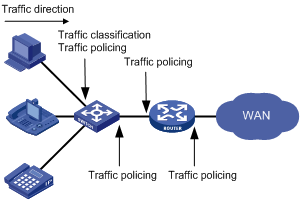
As shown in Figure 1, traffic classification and traffic policing mainly implement the following functions:
· Traffic classification—Uses match criteria to assign packets with the same characteristics to a traffic class. Based on traffic classes, you can provide differentiated services.
· Traffic policing—Polices flows and imposes penalties to prevent aggressive use of network resources. You can apply traffic policing to both incoming and outgoing traffic of a port.
QoS processing flow in a device
Figure 2 briefly describes how the QoS module processes traffic.
1. Traffic classifier identifies and classifies traffic for subsequent QoS actions.
2. The QoS module takes various QoS actions on classified traffic as configured, depending on the traffic processing phase and network status. For example, you can configure the QoS module to perform traffic policing for incoming traffic.
Configuring a QoS policy
You can configure QoS by using the MQC approach or non-MQC approach. Some features support both approaches, but some support only one.
Non-MQC approach
In the non-MQC approach, you configure QoS service parameters without using a QoS policy.
MQC approach
In the modular QoS configuration (MQC) approach, you configure QoS service parameters by using QoS policies. A QoS policy defines the policing or other QoS actions to take on different classes of traffic. It is a set of class-behavior associations.
A traffic class is a set of match criteria for identifying traffic, and it uses the AND or OR operator.
· If the operator is AND, a packet must match all the criteria to match the traffic class.
· If the operator is OR, a packet matches the traffic class if it matches any of the criteria in the traffic class.
A traffic behavior defines a set of QoS actions to take on packets, such as priority marking.
By associating a traffic behavior with a traffic class in a QoS policy, you apply QoS actions in the traffic behavior to the traffic class.
Configuration procedure diagram
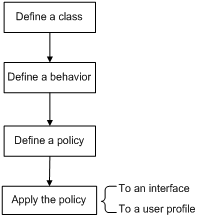
Figure 3 shows how to configure a QoS policy.
Figure 3 QoS policy configuration procedure
Defining a traffic class
|
Step |
Command |
Remarks |
|
1. Enter system view. |
system-view |
N/A |
|
2. Create a traffic class and enter traffic class view. |
traffic classifier classifier-name [ operator { and | or } ] |
By default, no traffic class exists. |
|
3. Configure match criteria. |
if-match [ not ] match-criteria |
By default, no match criterion is configured. For more information, see the if-match command in ACL and QoS Command Reference. |
Defining a traffic behavior
A traffic behavior is a set of QoS actions (such as traffic policing and priority marking) to take on a traffic class.
To define a traffic behavior:
|
Step |
Command |
Remarks |
|
1. Enter system view. |
system-view |
N/A |
|
2. Create a traffic behavior and enter traffic behavior view. |
traffic behavior behavior-name |
By default, no traffic behavior exists. |
|
3. Configure actions in the traffic behavior. |
See the subsequent chapters, depending on the purpose of the traffic behavior: traffic policing, traffic filtering, and priority marking. |
By default, no action is configured for a traffic behavior. |
Defining a QoS policy
To perform actions defined in a behavior for a class of packets, associate the behavior with the class in a QoS policy.
To associate a traffic class with a traffic behavior in a QoS policy:
|
Step |
Command |
Remarks |
|
1. Enter system view. |
system-view |
N/A |
|
2. Create a QoS policy and enter QoS policy view. |
qos policy policy-name |
By default, no QoS policy exists. |
|
3. Associate a traffic class with a traffic behavior to create a class-behavior association in the QoS policy. |
classifier classifier-name behavior behavior-name [ insert-before before-classifier-name ] |
By default, a traffic class is not associated with a traffic behavior. Repeat this step to create more class-behavior associations. |
Applying the QoS policy
You can apply a QoS policy to the following destinations:
· Interface—The QoS policy takes effect on the traffic sent or received on the interface.
· User profile—The QoS policy takes effect on the traffic sent or received by the online users of the user profile.
You can modify traffic classes, traffic behaviors, and class-behavior associations in a QoS policy even after it is applied. If a traffic class uses an ACL for traffic classification, you can delete or modify the ACL.
Applying the QoS policy to an interface
A QoS policy can be applied to multiple interfaces. However, only one QoS policy can be applied to one direction (inbound or outbound) of an interface.
The QoS policy applied to the outgoing traffic on an interface does not regulate local packets. Local packets refer to critical protocol packets sent by the local system for operation maintenance. The most common local packets include link maintenance, RIP, and SSH packets.
To apply a QoS policy to an interface:
|
Step |
Command |
Remarks |
|
1. Enter system view. |
system-view |
N/A |
|
2. Enter interface view. |
interface interface-type interface-number |
N/A |
|
3. Apply the QoS policy to the interface. |
qos apply policy policy-name { inbound | outbound } |
By default, no QoS policy is applied to an interface. |
Applying the QoS policy to a user profile
The following matrix shows the feature and hardware compatibility:
|
Hardware series |
Model |
Feature compatibility |
|
WX1800H series |
WX1804H WX1810H WX1820H |
Yes |
|
WX2500H series |
WX2510H WX2540H WX2560H |
Yes |
|
WX3000H series |
WX3010H WX3010H-L WX3010H-X WX3024H WX3024H-L |
No |
|
WX3500H series |
WX3508H WX3510H WX3520H WX3540H |
Yes |
|
WX5500E series |
WX5510E WX5540E |
Yes |
|
WX5500H series |
WX5540H WX5560H WX5580H |
Yes |
|
Access controller modules |
EWPXM1MAC0F EWPXM1WCME0 EWPXM2WCMD0F LSQM1WCMX20 LSQM1WCMX40 LSUM1WCME0 LSUM1WCMX20RT LSUM1WCMX40RT |
Yes |
You can apply a QoS policy to multiple user profiles. In one direction of each user profile, only one policy can be applied. To modify a QoS policy already applied to a direction, first remove the applied QoS policy.
To apply a QoS policy to a user profile:
|
Step |
Command |
Remarks |
|
1. Enter system view. |
system-view |
N/A |
|
2. Enter user profile view. |
user-profile profile-name |
The configuration made in user profile view takes effect only after it is successfully issued to the driver. |
|
3. Apply the QoS policy. |
qos apply policy policy-name { inbound | outbound } |
Use the inbound keyword to apply the QoS policy to the incoming traffic of the device (traffic sent by the online users). Use the outbound keyword to apply the QoS policy to the outgoing traffic of the device (traffic received by the online users). |
Displaying and maintaining QoS policies
Execute display commands in any view.
|
Task |
Command |
|
Display traffic class configuration. |
display traffic classifier { system-defined | user-defined } [ classifier-name ] [ slot slot-number ] |
|
Display traffic behavior configuration. |
display traffic behavior { system-defined | user-defined } [ behavior-name ] [ slot slot-number ] |
|
Display QoS policy configuration. |
display qos policy { system-defined | user-defined } [ policy-name [ classifier classifier-name ] ] [ slot slot-number ] |
|
Display information about QoS policies applied to interfaces. |
display qos policy interface [ interface-type interface-number ] [ inbound | outbound ] |
|
Display information about QoS policies applied to user profiles. |
display qos policy user-profile [ name profile-name ] [ user-id user-id ] [ slot slot-number ] [ inbound | outbound ] |
|
|
NOTE: Support for the display qos policy user-profile command depends on the device model. For more information, see ACL and QoS Command Reference. |
Configuring priority mapping
Overview
When a packet arrives, a device assigns a set of QoS priority parameters to the packet based on either of the following:
· A priority field carried in the packet.
· The port priority of the incoming port.
This process is called priority mapping. During this process, the device can modify the priority of the packet according to the priority mapping rules. The set of QoS priority parameters decides the scheduling priority and forwarding priority of the packet.
Priority mapping is implemented with priority maps and involves the following priorities:
· 802.11e priority.
· 802.1p priority.
· DSCP.
· IP precedence.
· Local precedence.
Introduction to priorities
Priorities include the following types: priorities carried in packets, and priorities locally assigned for scheduling only.
Packet-carried priorities include 802.1p priority, DSCP precedence, and IP precedence. These priorities have global significance and affect the forwarding priority of packets across the network. For more information about these priorities, see "Appendixes."
Locally assigned priorities only have local significance. They are assigned by the device only for scheduling. The device supports only local precedence for locally assigned priorities. A local precedence value corresponds to an output queue. A packet with higher local precedence is assigned to a higher priority output queue to be preferentially scheduled.
Priority maps
The device provides various types of priority maps. By looking through a priority map, the device decides which priority value to assign to a packet for subsequent packet processing.
The default priority maps (as shown in Appendix B Default priority maps) are available for priority mapping. They are adequate in most cases. If a default priority map cannot meet your requirements, you can modify the priority map as required.
Priority mapping configuration tasks
You can configure priority mapping by using any of the following methods:
· Configuring priority trust mode—In this method, you can configure a port to look up a trusted priority type (802.1p, for example) in incoming packets in the priority maps. Then, the system maps the trusted priority to the target priority types and values.
· Changing port priority—If no packet priority is trusted, the port priority of the incoming port is used. By changing the port priority of a port, you change the priority of the incoming packets on the port.
To configure priority mapping, perform the following tasks:
|
Tasks at a glance |
|
(Optional.) Configuring a priority map |
|
(Required.) Perform one of the following tasks: · Configuring a port to trust packet priority for priority mapping · Changing the port priority of an interface |
Configuring a priority map
The device provides the following types of priority map:
|
Priority map |
Description |
|
dot11e-lp |
802.11e-local priority map. |
|
dot1p-lp |
802.1p-local priority map. |
|
dscp-lp |
DSCP-local priority map. |
|
lp-dot11e |
Local-802.11e priority map. |
|
lp-dot1p |
Local-802.1p priority map. |
|
lp-dscp |
Local-DSCP priority map. |
To configure a priority map
|
Step |
Command |
Remarks |
|
1. Enter system view. |
system-view |
N/A |
|
2. Enter priority map view. |
qos map-table { dot11e-lp | dot1p-lp | dscp-lp | lp-dot11e | lp-dot1p | lp-dscp } |
N/A |
|
3. Configure mappings for the priority map. |
import import-value-list export export-value |
By default, the default priority maps are used. For more information, see "Appendixes." Newly configured mappings overwrite the old ones. |
Configuring a port to trust packet priority for priority mapping
You can configure the device to trust a particular priority field carried in packets for priority mapping on ports or globally.
When you configure the trusted packet priority type on an interface, use the following available keywords:
· dot1p—Uses the 802.1p priority of received packets for mapping.
· dscp—Uses the DSCP precedence of received IP packets for mapping.
To configure the trusted packet priority type on an interface:
|
Step |
Command |
Remarks |
|
1. Enter system view. |
system-view |
N/A |
|
2. Enter interface view. |
interface interface-type interface-number |
N/A |
|
3. Configure the trusted packet priority type. |
qos trust { dot1p | dscp } |
By default, the port priority is trusted. |
Changing the port priority of an interface
If an interface does not trust any packet priority, the device uses its port priority to look for priority parameters for the incoming packets. By changing port priority, you can prioritize traffic received on different interfaces.
To change the port priority of an interface:
|
Step |
Command |
Remarks |
|
1. Enter system view. |
system-view |
N/A |
|
2. Enter interface view. |
interface interface-type interface-number |
N/A |
|
3. Set the port priority of the interface. |
qos priority priority-value |
The default setting is 0. |
Displaying and maintaining priority mapping
Execute display commands in any view.
|
Task |
Command |
|
Display priority map configuration. |
display qos map-table [ dot11e-lp | dot1p-lp | dscp-lp | lp-dot11e | lp-dot1p | lp-dscp ] |
|
Display the trusted packet priority type on a port. |
display qos trust interface [ interface-type interface-number ] |
Priority mapping configuration examples
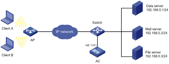
Network requirements
As shown in Figure 4:
· The IP precedence of traffic from Device A to the AC is 3.
· The IP precedence of traffic from Device B to the AC is 1.

Configuration procedure
# Assign port priority to GigabitEthernet 1/0/1 and GigabitEthernet 1/0/2. Make sure the following requirements are met:
· The priority of GigabitEthernet 1/0/1 is higher than that of GigabitEthernet 1/0/2.
· No trusted packet priority type is configured on GigabitEthernet 1/0/1 or GigabitEthernet 1/0/2.
<AC> system-view
[AC] interface gigabitethernet 1/0/1
[AC-GigabitEthernet1/0/1] qos priority 3
[AC-GigabitEthernet1/0/1] quit
[AC] interface gigabitethernet 1/0/2
[AC-GigabitEthernet1/0/2] qos priority 1
[AC-GigabitEthernet1/0/2] quit
Configuring traffic policing
Overview
Traffic policing helps assign network resources (including bandwidth) and increase network performance. For example, you can configure a flow to use only the resources committed to it in a certain time range. This avoids network congestion caused by burst traffic.
Traffic policing controls the traffic rate and resource usage according to traffic specifications. You can use token buckets for evaluating traffic specifications.
Traffic evaluation and token buckets
Token bucket features
A token bucket is analogous to a container that holds a certain number of tokens. Each token represents a certain forwarding capacity. The system puts tokens into the bucket at a constant rate. When the token bucket is full, the extra tokens cause the token bucket to overflow.
Evaluating traffic with the token bucket mechanism
The token bucket mechanism evaluates each packet by looking at the number of tokens in the bucket. If the number of tokens in the bucket is enough for forwarding a packet:
· The packet conforms to the specification (called conforming traffic) and is colored green.
· The corresponding tokens are taken away from the bucket.
Otherwise, the packet does not conform to the specification (called excess traffic) and is colored red.
Traffic policing uses the single rate two color mechanism. This mechanism uses one token bucket (bucket C) and the following parameters:
· Committed information rate (CIR)—Mean rate at which tokens are put into bucket C. It sets the average packet transmission or forwarding rate allowed by bucket C.
· Committed burst size (CBS)—Size of bucket C, which specifies the transient burst of traffic that bucket C can forward in each burst. The CBS must be greater than the maximum packet size.
Traffic policing
Traffic policing supports policing the inbound traffic and the outbound traffic.
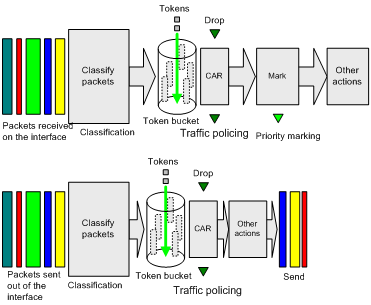
A typical application of traffic policing is to supervise the specification of traffic entering a network and limit it within a reasonable range. Another application is to "discipline" the extra traffic to prevent aggressive use of network resources by an application. For example, you can limit bandwidth for HTTP packets to less than 50% of the total. If the traffic of a session exceeds the limit, traffic policing can drop the packets or reset the IP precedence of the packets. Figure 5 shows an example of policing outbound traffic on an interface.
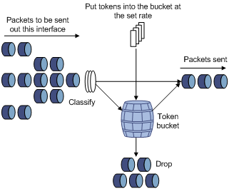
Traffic policing is widely used in policing traffic entering the ISP networks. It can classify the policed traffic and take predefined policing actions on each packet depending on the evaluation result:
· Forwarding the packet if the evaluation result is "conforming."
· Dropping the packet if the evaluation result is "excess."
Configuration procedure
You can configure traffic policing for an interface only by using the MQC approach. You can configure traffic policing for a user profile by using the MQC approach or non-MQC approach.
Configuring traffic policing by using the MQC approach
|
Step |
Command |
Remarks |
|
1. Enter system view. |
system-view |
N/A |
|
2. Create a traffic class and enter traffic class view. |
traffic classifier classifier-name [ operator { and | or } ] |
By default, no traffic class exists. |
|
3. Configure match criteria. |
if-match [ not ] match-criteria |
By default, no match criterion is configured. For more information about the if-match command, see ACL and QoS Command Reference. |
|
4. Return to system view. |
quit |
N/A |
|
5. Create a traffic behavior and enter traffic behavior view. |
traffic behavior behavior-name |
By default, no traffic behavior exists. |
|
6. Configure a traffic policing action. |
car cir committed-information-rate [ cbs committed-burst-size ] [ green action | red action | yellow action ] * |
By default, no traffic policing action is configured. |
|
7. Return to system view. |
quit |
N/A |
|
8. Create a QoS policy and enter QoS policy view. |
qos policy policy-name |
By default, no QoS policy exists. |
|
9. Associate the traffic class with the traffic behavior in the QoS policy. |
classifier classifier-name behavior behavior-name |
By default, a traffic class is not associated with a traffic behavior. |
|
10. Return to system view. |
quit |
N/A |
|
11. Apply the QoS policy. |
Choose one of the application destinations as needed. By default, no QoS policy is applied. |
Configuring traffic policing for a user profile by using the non-MQC approach
The following matrix shows the feature and hardware compatibility:
|
Hardware series |
Model |
Feature compatibility |
|
WX1800H series |
WX1804H WX1810H WX1820H |
Yes |
|
WX2500H series |
WX2510H WX2540H WX2560H |
Yes |
|
WX3000H series |
WX3010H WX3010H-L WX3010H-X WX3024H WX3024H-L |
No |
|
WX3500H series |
WX3508H WX3510H WX3520H WX3540H |
Yes |
|
WX5500E series |
WX5510E WX5540E |
Yes |
|
WX5500H series |
WX5540H WX5560H WX5580H |
Yes |
|
Access controller modules |
EWPXM1MAC0F EWPXM1WCME0 EWPXM2WCMD0F LSQM1WCMX20 LSQM1WCMX40 LSUM1WCME0 LSUM1WCMX20RT LSUM1WCMX40RT |
Yes |
When a user profile is configured, you can perform traffic policing based on users. When any user of the user profile logs in, the authentication server automatically applies the CAR parameters configured for the user profile to the user. When the user logs off, the system automatically removes the CAR configuration without manual intervention.
To configure traffic policing for a user profile:
|
Step |
Command |
Remarks |
|
1. Enter system view. |
system-view |
N/A |
|
2. Enter user profile view. |
user-profile profile-name |
The configuration made in user profile view takes effect when the users are online. |
|
3. Configure a CAR policy for the user profile. |
qos car { inbound | outbound } any cir committed-information-rate [ cbs committed-burst-size ] |
By default, no CAR policy is configured for a user profile. The conforming traffic is permitted to pass through, and the excess traffic is dropped. |
Displaying and maintaining traffic policing
Execute display commands in any view.
|
Task |
Command |
|
Display traffic behavior configuration. |
display traffic behavior { system-defined | user-defined } [ behavior-name ] [ slot slot-number ] |
Configuring traffic filtering
You can filter in or filter out traffic of a class by associating the class with a traffic filtering action. For example, you can filter packets sourced from an IP address according to network status.
Configuration procedure
To configure traffic filtering:
|
Step |
Command |
Remarks |
|
1. Enter system view. |
system-view |
N/A |
|
2. Create a traffic class and enter traffic class view. |
traffic classifier classifier-name [ operator { and | or } ] |
By default, no traffic class exists. |
|
3. Configure match criteria. |
if-match [ not ] match-criteria |
By default, no match criterion is configured. |
|
4. Return to system view. |
quit |
N/A |
|
5. Create a traffic behavior and enter traffic behavior view. |
traffic behavior behavior-name |
By default, no traffic behavior exists. |
|
6. Configure the traffic filtering action. |
filter { deny | permit } |
By default, no traffic filtering action is configured. |
|
7. Return to system view. |
quit |
N/A |
|
8. Create a QoS policy and enter QoS policy view. |
qos policy policy-name |
By default, no QoS policy exists. |
|
9. Associate the traffic class with the traffic behavior in the QoS policy. |
classifier classifier-name behavior behavior-name |
By default, a traffic class is not associated with a traffic behavior. |
|
10. Return to system view. |
quit |
N/A |
|
11. Apply the QoS policy to an interface. |
By default, no QoS policy is applied to an interface. |
|
|
12. (Optional.) Display the traffic filtering configuration. |
display traffic behavior { system-defined | user-defined } [ behavior-name ] [ slot slot-number ] |
Available in any view. |
Configuration example
Network requirements
As shown in Figure 6, configure traffic filtering on GigabitEthernet 1/0/1 to deny the incoming packets with a source port number other than 21.
Configuration procedure
# Create advanced ACL 3000, and configure a rule to match packets whose source port number is not 21.
<AC> system-view
[AC] acl advanced 3000
[AC-acl-ipv4-adv-3000] rule 0 permit tcp source-port neq 21
[AC-acl-ipv4-adv-3000] quit
# Create a traffic class named classifier_1, and use ACL 3000 as the match criterion in the traffic class.
[AC] traffic classifier classifier_1
[AC-classifier-classifier_1] if-match acl 3000
[AC-classifier-classifier_1] quit
# Create a traffic behavior named behavior_1, and configure the traffic filtering action to drop packets.
[AC] traffic behavior behavior_1
[AC-behavior-behavior_1] filter deny
[AC-behavior-behavior_1] quit
# Create a QoS policy named policy, and associate traffic class classifier_1 with traffic behavior behavior_1 in the QoS policy.
[AC] qos policy policy
[AC-qospolicy-policy] classifier classifier_1 behavior behavior_1
[AC-qospolicy-policy] quit
# Apply the QoS policy named policy to the incoming traffic of GigabitEthernet 1/0/1.
[AC] interface gigabitethernet 1/0/1
[AC-GigabitEthernet1/0/1] qos apply policy policy inbound
Configuring priority marking
Priority marking sets the priority fields or flag bits of packets to modify the priority of packets. For example, you can use priority marking to set the DSCP value for a class of IP packets to control the forwarding of these packets.
1. Configure a traffic behavior with a priority marking action.
2. Associate the traffic class with the traffic behavior.
Priority marking can be used together with priority mapping. For more information, see "Configuring priority mapping."
Configuration procedure
To configure priority marking:
|
Step |
Command |
Remarks |
|
1. Enter system view. |
system-view |
N/A |
|
2. Create a traffic class and enter traffic class view. |
traffic classifier classifier-name [ operator { and | or } ] |
By default, no traffic class exists. |
|
3. Configure match criteria. |
if-match [ not ] match-criteria |
By default, no match criterion is configured. For more information about the if-match command, see ACL and QoS Command Reference. |
|
4. Return to system view. |
quit |
N/A |
|
5. Create a traffic behavior and enter traffic behavior view. |
traffic behavior behavior-name |
By default, no traffic behavior exists. |
|
6. Configure a priority marking action. |
· Set the DSCP value for packets: · Set the local precedence for packets: |
Use one of the commands. By default, no priority marking action is configured. |
|
7. Return to system view. |
quit |
N/A |
|
8. Create a QoS policy and enter QoS policy view. |
qos policy policy-name |
By default, no QoS policy exists. |
|
9. Associate the traffic class with the traffic behavior in the QoS policy. |
classifier classifier-name behavior behavior-name |
By default, a traffic class is not associated with a traffic behavior. |
|
10. Return to system view. |
quit |
N/A |
|
11. Apply the QoS policy to an interface. |
By default, no QoS policy is applied to an interface. |
|
|
12. (Optional.) Display the priority marking configuration. |
display traffic behavior { system-defined | user-defined } [ behavior-name ] [ slot slot-number ] |
Available in any view. |
Configuration example
Network requirements
As shown in Figure 7, configure priority marking on the AC to meet the following requirements:
|
Traffic source |
Destination |
Processing priority |
|
Client A, B |
Data server |
High |
|
Client A, B |
Mail server |
Medium |
|
Client A, B |
File server |
Low |
Configuration procedure
# Create advanced ACL 3000, and configure a rule to match packets with destination IP address 192.168.0.1.
<AC> system-view
[AC] acl advanced 3000
[AC-acl-ipv4-adv-3000] rule permit ip destination 192.168.0.1 0
[AC-acl-ipv4-adv-3000] quit
# Create advanced ACL 3001, and configure a rule to match packets with destination IP address 192.168.0.2.
[AC] acl advanced 3001
[AC-acl-ipv4-adv-3001] rule permit ip destination 192.168.0.2 0
[AC-acl-ipv4-adv-3001] quit
# Create advanced ACL 3002, and configure a rule to match packets with destination IP address 192.168.0.3.
[AC] acl advanced 3002
[AC-acl-ipv4-adv-3002] rule permit ip destination 192.168.0.3 0
[AC-acl-ipv4-adv-3002] quit
# Create a traffic class named classifier_dbserver, and use ACL 3000 as the match criterion in the traffic class.
[AC] traffic classifier classifier_dbserver
[AC-classifier-classifier_dbserver] if-match acl 3000
[AC-classifier-classifier_dbserver] quit
# Create a traffic class named classifier_mserver, and use ACL 3001 as the match criterion in the traffic class.
[AC] traffic classifier classifier_mserver
[AC-classifier-classifier_mserver] if-match acl 3001
[AC-classifier-classifier_mserver] quit
# Create a traffic class named classifier_fserver, and use ACL 3002 as the match criterion in the traffic class.
[AC] traffic classifier classifier_fserver
[AC-classifier-classifier_fserver] if-match acl 3002
[AC-classifier-classifier_fserver] quit
# Create a traffic behavior named behavior_dbserver, and configure the action of setting the local precedence value to 4.
[AC] traffic behavior behavior_dbserver
[AC-behavior-behavior_dbserver] remark local-precedence 4
[AC-behavior-behavior_dbserver] quit
# Create a traffic behavior named behavior_mserver, and configure the action of setting the local precedence value to 3.
[AC] traffic behavior behavior_mserver
[AC-behavior-behavior_mserver] remark local-precedence 3
[AC-behavior-behavior_mserver] quit
# Create a traffic behavior named behavior_fserver, and configure the action of setting the local precedence value to 2.
[AC] traffic behavior behavior_fserver
[AC-behavior-behavior_fserver] remark local-precedence 2
[AC-behavior-behavior_fserver] quit
# Create a QoS policy named policy_server, and associate traffic classes with traffic behaviors in the QoS policy.
[AC] qos policy policy_server
[AC-qospolicy-policy_server] classifier classifier_dbserver behavior behavior_dbserver
[AC-qospolicy-policy_server] classifier classifier_mserver behavior behavior_mserver
[AC-qospolicy-policy_server] classifier classifier_fserver behavior behavior_fserver
[AC-qospolicy-policy_server] quit
# Apply the QoS policy named policy_server to the incoming traffic of GigabitEthernet 1/0/1.
[AC] interface gigabitethernet 1/0/1
[AC-GigabitEthernet1/0/1] qos apply policy policy_server inbound
[AC-GigabitEthernet1/0/1] quit
Appendixes
Appendix A Acronym
Table 1 Appendix A Acronym
|
Acronym |
Full spelling |
|
BE |
Best Effort |
|
CAR |
Committed Access Rate |
|
CBS |
Committed Burst Size |
|
CIR |
Committed Information Rate |
|
DiffServ |
Differentiated Service |
|
DSCP |
Differentiated Services Code Point |
|
EBS |
Excess Burst Size |
|
IntServ |
Integrated Service |
|
ISP |
Internet Service Provider |
|
PIR |
Peak Information Rate |
|
QoS |
Quality of Service |
|
ToS |
Type of Service |
Appendix B Default priority maps
Table 2 Default dot1p-lp priority map
|
Input priority value |
dot1p-lp map |
|
dot1p |
lp |
|
0 |
2 |
|
1 |
0 |
|
2 |
1 |
|
3 |
3 |
|
4 |
4 |
|
5 |
5 |
|
6 |
6 |
|
7 |
7 |
Table 3 Default dot11e-lp priority map
|
dot11e |
lp |
|
0 |
2 |
|
1 |
0 |
|
2 |
1 |
|
3 |
3 |
|
4 |
4 |
|
5 |
5 |
|
6 |
6 |
|
7 |
7 |
Table 4 Default dscp-lp priority map
|
Input priority value |
dscp-lp map |
|
dscp |
lp |
|
0 to 7 |
0 |
|
8 to 15 |
1 |
|
16 to 23 |
2 |
|
24 to 31 |
3 |
|
32 to 39 |
4 |
|
40 to 47 |
5 |
|
48 to 55 |
6 |
|
56 to 63 |
7 |
Table 5 Default lp-dot1p, lp-dot11e, and lp-dscp priority maps
|
Input priority value |
lp-dot1p map |
lp-dot11e map |
lp-dscp map |
|
lp |
dot1p |
dot11e |
DSCP |
|
0 |
1 |
1 |
0 |
|
1 |
2 |
2 |
8 |
|
2 |
0 |
0 |
16 |
|
3 |
3 |
3 |
24 |
|
4 |
4 |
4 |
32 |
|
5 |
5 |
5 |
40 |
|
6 |
6 |
6 |
48 |
|
7 |
7 |
7 |
56 |
Table 6 Default port priority-local priority map
|
Port priority |
Local precedence |
|
0 |
0 |
|
1 |
1 |
|
2 |
2 |
|
3 |
3 |
|
4 |
4 |
|
5 |
5 |
|
6 |
6 |
|
7 |
7 |
Appendix C Introduction to packet precedences
IP precedence and DSCP values
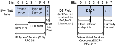
As shown in Figure 8, the ToS field in the IP header contains 8 bits. The first 3 bits (0 to 2) represent IP precedence from 0 to 7. According to RFC 2474, the ToS field is redefined as the differentiated services (DS) field. A DSCP value is represented by the first 6 bits (0 to 5) of the DS field and is in the range 0 to 63. The remaining 2 bits (6 and 7) are reserved.
Table 7 IP precedence
|
IP precedence (decimal) |
IP precedence (binary) |
Description |
|
0 |
000 |
Routine |
|
1 |
001 |
priority |
|
2 |
010 |
immediate |
|
3 |
011 |
flash |
|
4 |
100 |
flash-override |
|
5 |
101 |
critical |
|
6 |
110 |
internet |
|
7 |
111 |
network |
Table 8 DSCP values
|
DSCP value (decimal) |
DSCP value (binary) |
Description |
|
46 |
101110 |
ef |
|
10 |
001010 |
af11 |
|
12 |
001100 |
af12 |
|
14 |
001110 |
af13 |
|
18 |
010010 |
af21 |
|
20 |
010100 |
af22 |
|
22 |
010110 |
af23 |
|
26 |
011010 |
af31 |
|
28 |
011100 |
af32 |
|
30 |
011110 |
af33 |
|
34 |
100010 |
af41 |
|
36 |
100100 |
af42 |
|
38 |
100110 |
af43 |
|
8 |
001000 |
cs1 |
|
16 |
010000 |
cs2 |
|
24 |
011000 |
cs3 |
|
32 |
100000 |
cs4 |
|
40 |
101000 |
cs5 |
|
48 |
110000 |
cs6 |
|
56 |
111000 |
cs7 |
|
0 |
000000 |
be (default) |
802.1p priority
802.1p priority lies in the Layer 2 header. It applies to occasions where Layer 3 header analysis is not needed and QoS must be assured at Layer 2.
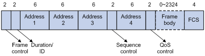
Figure 9 An Ethernet frame with an 802.1Q tag header
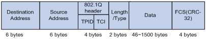
As shown in Figure 9, the 4-byte 802.1Q tag header contains the 2-byte tag protocol identifier (TPID) and the 2-byte tag control information (TCI). The value of the TPID is 0x8100. Figure 10 shows the format of the 802.1Q tag header. The Priority field in the 802.1Q tag header is called 802.1p priority, because its use is defined in IEEE 802.1p. Table 9 shows the values for 802.1p priority.
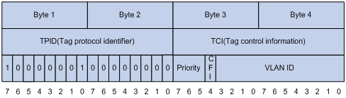
Table 9 Description on 802.1p priority
|
802.1p priority (decimal) |
802.1p priority (binary) |
Description |
|
0 |
000 |
best-effort |
|
1 |
001 |
background |
|
2 |
010 |
spare |
|
3 |
011 |
excellent-effort |
|
4 |
100 |
controlled-load |
|
5 |
101 |
video |
|
6 |
110 |
voice |
|
7 |
111 |
network-management |
802.11e priority
To provide QoS services on WLAN, the 802.11e standard was developed. IEEE 802.11e is a MAC-layer enhancement to IEEE 802.11. IEEE 802.11e adds a 2-byte QoS control field to the 802.11e MAC frame header. The 3-bit QoS control field represents the 802.11e priority in the range of 0 to 7.
Figure 11 802.11e frame structure