- Table of Contents
- Related Documents
-
| Title | Size | Download |
|---|---|---|
| 03-ACFP Configuration | 301.15 KB |
Contents
Configuring the connection mode for an internal interface on an OAP module
Enabling the ACFP trap function
Displaying and maintaining ACFP
|
|
NOTE: In this documentation, SPC cards refer to the interface cards prefixed with SPC, for example, SPC-GT48L. SPE cards refer to the base cards prefixed with SPE, for example, SPE-1020-E. |
ACFP overview
Basic data communication networks comprise of routers and switches, which forward data packets. As data networks develop, more and more services run on them. It has become inappropriate to use legacy routers for handling some new services. Therefore, some security products such as firewalls, Intrusion Detection System (IDS), and Intrusion Prevention System (IPS), and voice and wireless products are designed to handle specific services.
For better support of new services, manufacturers of legacy networking devices (routers and switches in this document) have developed various dedicated service boards (cards) to specifically handle these services. Some manufacturers of legacy networking devices provide a set of software/hardware interfaces to allow the boards (cards) or devices of other manufacturers to be plugged or connected to these legacy networking devices for cooperating to handle these services. This gives full play to the advantages of respective manufacturers for better support of new services while reducing user investments.
The open application architecture (OAA) is an open service architecture developed with this concept. It integrates routers and software produced by different manufacturers, making them function as one router, and thus providing integrated resolutions for the customers.
The Application Control Forwarding Protocol (ACFP) is developed based on the OAA architecture. For example, collaborating IPS/IDS cards or IPS/IDS devices acting as ACFP clients run software packages developed by other manufacturers to support the IPS/IDS services. A router or switch mirrors or redirects the received packets to an ACFP client after matching the ACFP collaboration rules. The software running on the ACFP client monitors and detects the packets. Based on the monitoring and detection results, the ACFP client sends back responses to the router or switch through collaboration Management Information Bases (MIBs) to instruct the router or switch to process the results, such as filtering out the specified packets.
|
|
NOTE: Only IM-IPS and IM-ACG cards support ACFP. |
ACFP architecture
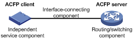
As shown in Figure 1, the ACFP architecture consists of:
· Routing/switching component—As the main part of a routers and a switch, it performs complete router/switch functions and is also the core of user management control. This part is called the ACFP server.
· Independent service component—It is the main part open for development by a third party and is mainly used to provide various unique service functions. This part is called the ACFP client.
· Interface-connecting component—It connects the interface of the routing/switching component to that of the independent service component, allowing the routers of two manufacturers to be interconnected.
ACFP collaboration
ACFP collaboration means that the independent service component can send instructions to the routing/switching component to change its functions. ACFP collaboration is mainly implemented through the Simple Network Management Protocol (SNMP). Acting as a network management system, the independent service component sends various SNMP commands to the routing/switching component, which can then execute the instructions received because it supports SNMP agent. In this process, the cooperating MIB is the key to associating the two components with each other.
ACFP management
ACFP collaboration provides a mechanism that enables the ACFP client to control the traffic on the ACFP server by implementing the following functions:
· Mirroring and redirecting the traffic on the ACFP server to the ACFP client
· Permitting/denying the traffic from the ACFP server
· Restricting the rate of the traffic on the ACFP server
· Carrying the context ID in a packet to enable the ACFP server and ACFP client to communicate the packet context with each other. The detailed procedure is as follows:
The ACFP server maintains a context table that can be queried with context ID. Each context ID corresponds with an ACFP collaboration policy that contains information including inbound interface and outbound interface of the packet, and collaboration rules. When the packet received by the ACFP server is redirected or mirrored to the ACFP client after matching a collaboration rule, the packet carries the context ID of the collaboration policy to which the collaboration rule belongs. When the redirected packet is returned from the ACFP client, the packet also carries the context ID. With the context ID, the ACFP server knows that the packet is returned after being redirected and then forwards the packet normally.
For the ACFP client to better control traffic, the two-level structure of collaboration policy and collaboration rules is set in the collaboration to manage the traffic matching the collaboration rule based on the collaboration policy, implementing flexible traffic management.
To better support the Client/Server collaboration mode and granularly and flexibly set different rules, the collaboration content is divided into four parts: ACFP server information, ACFP client information, ACFP collaboration policy and ACFP collaboration rules. These four parts of information are saved in the ACFP server.
An ACFP server supports multiple ACFP clients. Therefore, ACFP client information, ACFP collaboration policy, and ACFP collaboration rules are organized in the form of tables.
ACFP server information is generated by the ACFP server itself. ACFP client information, ACFP collaboration policy, and ACFP collaboration rules are generated on the ACFP client and sent to the ACFP server through the collaboration MIB or collaboration protocol.
ACFP information overview
ACFP server information
ACFP server information contains the following:
· Supported working modes—host, pass-through, mirroring, and redirect. An ACFP server can support multiple working modes among these four at the same time. The ACFP server and client(s) can collaborate with each other only when the ACFP server supports the working mode of the ACFP client.
· Maximum expiration time of the supported collaboration policy—This indicates for how long the collaboration policy of the ACFP server will remain valid.
· Whether the ACFP server can permanently save the collaboration policy—It mainly refers to whether the ACFP server can keep the original collaboration policy after reboot.
· Currently supported context ID type—The location of the context ID in the packet is HGPlus-context (carrying the preamble HGPlus as the context ID).
The above-mentioned information indicates the collaboration capabilities of an ACFP server. ACFP clients can access this information through a collaboration protocol or collaboration MIB.
ACFP client information
ACFP client information contains the following:
· ACFP client identifier. It can be assigned by the ACFP server through a collaboration protocol or specified by the network administrator to make sure that each ACFP client has a unique client ID on the ACFP server.
· Description—ACFP client description information.
· Hw-Info—ACFP client hardware type, version number, and so on.
· OS-Info—System name and version number of the ACFP client.
· App-Info—Application software type and version number of the ACFP client.
· Client IP—ACFP client IP address.
· Client Mode—Working mode currently supported by the ACFP client, namely, the combination of the host, pass-through, mirroring, and redirect modes.
ACFP collaboration policy
ACFP collaboration policy refers to the collaboration policy that the ACFP client sends to the ACFP server for application. The policy information is as follows:
· Client ID—ACFP client identifier.
· Policy-Index
· In-interface—Interface through which the packet is sent to the ACFP server.
· Out-interface—Interface through which the packet is forwarded normally.
· Dest-interface—ACFP server interface connected with ACFP client.
· Context ID—It is used when the packet is mirrored or redirected to an ACFP client. After the interface connected to the ACFP client is specified in the policy sent, the ACFP server assigns it a global serial number, that is, the Context ID, with each Context ID corresponding to an ACFP collaboration policy.
· Admin-Status—It indicates whether to enable the policy.
· Effect-Status—It indicates the expiration time of the policy and is used to control the expiration time of all the rules under the policy.
· Start-Time—It indicates starting from what time (second/minute/hour) the policy takes effect and is used to control starting from what time all the rules under the policy take effect.
· End-time—It indicates starting from what time (second/minute/hour) the policy turns invalid and is used to control starting from what time all the rules under the policy turn invalid.
· DestIfFailAction—If the policy dest-interface is down, the actions to all rules under the policy will be as follows—for forwarding first routers, select the delete action to keep the redirected and mirrored packets being forwarded; for security first routers, select the reserve action to discard the redirected and mirrored packets.
· Priority—It indicates the priority of a policy, number notation, in the range of 1 to 8. The bigger the number, the higher the priority.
ACFP collaboration rules
ACFP collaboration rules refer to the collaboration rules that the ACFP client sends to the ACFP server for application. There are three types of collaboration rules:
· Monitoring rules—Monitoring, analyzing, and processing the packets to be sent to the ACFP client. The action types corresponding to monitoring rules are redirect and mirror.
· Filtering rules—Determining which packets to deny and which packets to permit. The action types corresponding to filtering rules are deny and permit.
· Restricting rules—Determining the rate of which packets is to be restricted. The action type corresponding to restricting rules is rate.
Rule information is described as follows:
· ClientID—ACFP client identifier.
· Policy index
· Rule index—rule identifier
· Status—It indicates whether the rule is applied successfully.
· Action—It can be mirror, redirect, deny, permit, or rate.
· Match all packets—It indicates whether to match all the packets. If yes, the following matching needs not be performed.
· Source MAC address
· Destination MAC address
· Starting VLAN ID
· Ending VLAN ID
· Protocol number in IP
· Source IP address
· Wildcard mask of source IP address
· Source port operator—Its type can be equal to, not equal to, greater than, less than, greater than and less than. The following ending source port number takes effect only when the type is greater than and less than. The source port number of the packets matched by the identifier must be greater than the starting source port number and less than the ending source port number.
· Starting source port number
· Ending source port number
· Destination IP address
· Wildcard mask of destination IP address
· Destination port number operator—Its type can be equal to, not equal to, greater than, less than, greater than and less than. The following ending destination port number is meaning only when the type is greater than and less than. The destination port number of the packets matched by the identifier must be greater than the starting destination port number and less than the ending destination port number.
· Starting destination port number
· Ending destination port number
· Pro—Protocol type, which can be GRE, ICMP, IGMP, OSPF, TCP, UDP, and IP.
· IP precedence—Packet precedence, a number in the range of 0 to 7.
· IP ToS—Type of Service (ToS) of IP
· IP DSCP—Differentiated Services Code Point (DSCP) of IP
· TCP flag—It indicates that some bits in the six flag bits (URG, ACK, PSH, RST, SYN, FIN) are concerned.
· IP fragment—It indicates whether the packet is an IP packet fragment.
· Rate limit
You can use the collaboration policy to manage the collaboration rules that belong to it.
Using ACFP
· ACFP does not support policy-based routing services or NetStream services.
· The handling of the packets redirected by ACFP is mutually exclusive with ordinary ACL rules. No QoS processing is performed on the packets returned after they are redirected to the ACFP client.
· A stream cannot be mirrored or redirected to multiple ACFP clients.
· ACFP does not support applying flow redirect policies to an aggregate interface.
· SPE cards support applying flow redirect policies only to Layer 3 interfaces.
· If a Layer 3 interface is added into an aggregation group, or an aggregate interface leaves an aggregation group, the configured flow redirect policies on the interface will become ineffective and you need to first delete the original flow redirect policies and then configure new policies on the interface.
· When the ACFP server is enabled, the internal interface cannot act as the source port for port mirroring.
· When ACFP server is enabled on an IM-IPS or IM-ACG card, the connection mode for the internal interface must be set to extend, the internal interface must be configured as a trunk port, and the PVID of the internal interface cannot be the VLAN ID of the management VLAN.
· When the connection mode of the internal interface on an IM-IPS or IM-ACG card is set to extend, you cannot specify a VLAN as both the user service VLAN and the management VLAN.
ACFP configuration task list
Complete the following tasks to configure ACFP:
|
Task |
Remarks |
|
Required |
|
|
Configuring the connection mode for an internal interface on an OAP module |
Required |
|
Optional |
Enabling the ACFP server
To configure to enable the ACFP server:
|
Step |
Command |
Remarks |
|
1. Enter system view. |
system-view |
N/A |
|
2. Enable the ACFP server. |
acfp server enable |
Disabled by default. |
Configuring the connection mode for an internal interface on an OAP module
The OAP module integrates a front card and a rear card. The front card provides value-added security services, such as firewall, intrusion prevention, and application control. The rear card is responsible for the data exchange between the front card and the router.
An internal interface is a virtual interface that is used for the data communication between the front and rear cards, as shown in Figure 2.
Figure 2 Schematic diagram for the internal interface
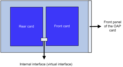
When configuring ACFP on an OAP module, to ensure the normal communication between the router and the OAP module, you must configure the connection mode for the OAP module internal interface as extend.
To configure the connection mode for an internal interface:
|
Step |
Command |
Remarks |
|
1. Enter system view. |
system-view |
N/A |
|
2. Enter internal interface view. |
interface interface-type interface-number |
N/A |
|
3. Configure the connection mode for the internal interface. |
port connection-mode { extend | normal } |
normal by default. |
|
|
NOTE: · For more information about the port connection-mode command, see Layer 2—LAN Switching Command Reference. · When you disable the ACSEI function or change the connection mode for an internal interface, to avoid disrupting the traffic, perform the operation on the ACFP client first, and then on the ACFP server. · Spanning Tree Protocol (STP) cannot be enabled on the internal interface of an IM-IPS or IM-ACG card. For more information about STP, see Layer 2—LAN Switching Configuration Guide. |
Enabling the ACFP trap function
To make ACFP work normally, you must enable the router to send traps of the ACFP module.
After the trap function on the ACFP module is enabled, the ACFP module will generate traps to report important events of the module. The levels of the ACFP traps are described in Table 1.
Table 1 ACFP trap message level
|
Trap message |
Level |
|
Context ID type changed |
notifications |
|
ACFP client registration |
notifications |
|
ACFP client deregistration |
notifications |
|
ACSEI detects that ACFP client had no response |
warnings |
|
ACFP server does not support the working mode of the ACFP client |
errors |
|
Expiration period of ACFP collaboration policy changed |
notifications |
|
ACFP collaboration rules are created |
informational |
|
ACFP collaboration rules are removed |
informational |
|
ACFP collaboration rules failed |
errors |
|
Expiration period of ACFP collaboration policy timed out |
notifications |
The generated traps will be sent to the information center of the router. With the parameters for the information center set, the output rules for traps (that is, whether the traps are allowed to be output and the output destinations) are decided. For the configuration of the parameters for the information center, see Network Management and Monitoring Configuration Guide.
To enable the ACFP function:
|
Step |
Command |
Remarks |
|
1. Enter system view. |
system-view |
N/A |
|
2. Enable the trap function of the ACFP module. |
snmp-agent trap enable acfp [ client | policy | rule | server ] |
Optional. Enabled by default. |
|
|
NOTE: For more information about the snmp-agent trap enable command, see Network Management and Monitoring Command Reference. |
Displaying and maintaining ACFP
|
Task |
Command |
Remarks |
|
Display the configuration information of the ACFP server. |
display acfp server-info [ | { begin | exclude | include } regular-expression ] |
Available in any view |
|
Display the configuration information of an ACFP client. |
display acfp client-info [ client-id ] [ | { begin | exclude | include } regular-expression ] |
|
|
Display the configuration information of an ACFP policy. |
display acfp policy-info [ client client-id [ policy-index ] | dest-interface interface-type interface-number | global | in-interface interface-type interface-number | out-interface interface-type interface-number ] [ active | inactive ] [ | { begin | exclude | include } regular-expression ] |
|
|
Display ACFP rule configuration information. |
display acfp rule-info { global | in-interface [ interface-type interface-number ] | out-interface [ interface-type interface-number ] | policy [ client-id policy-index ] } [ | { begin | exclude | include } regular-expression ] |
|
|
Display the configuration information of ACFP Trap. |
display snmp-agent trap-list [ | { begin | exclude | include } regular-expression ] |
ACFP configuration example
Network requirements
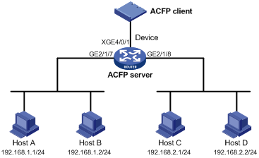
Different departments are interconnected on the intranet through Device, which serves as the ACFP server. An ACFP client is inserted in Device.
Configure the ACFP client to analyze traffic arriving at interface GigabitEthernet 2/1/7, and control the traffic as follows:
· Permit all packets with the source IP address 192.168.1.1/24.
· Deny all packets with the source IP address 192.168.1.2/24.
Figure 3 Network diagram
Configuration procedure
1. Configure Router:
# Enable the ACFP server.
<Router> system-view
[Router] acfp server enable
[Router] acsei server enable
# Assign an IP address to the VLAN interface of the management VLAN.
[Router] vlan 4093
[Router-vlan4093] interface Vlan-interface 4093
[Router-Vlan-interface4093] undo shutdown
[Router-Vlan-interface4093] ip address 40.94.1.1 24
[Router-Vlan-interface4093] quit
# Configure the internal interface Ten-GigabitEthernet 4/0/1 on the ACFP client as a trunk port, and assign the trunk port to VLAN 4094, which is not allowed to learn MAC addresses. Then, set the working mode for the internal Ethernet interface to extended.
[Router] interface Ten-GigabitEthernet 4/0/1
[Router-Ten-GigabitEthernet4/0/1] undo shutdown
[Router-Ten-GigabitEthernet4/0/1] port link-type trunk
[Router-Ten-GigabitEthernet4/0/1] port trunk permit vlan 4093
[Router-Ten-GigabitEthernet4/0/1] mac-address max-mac-count 0
[Router-Ten-GigabitEthernet4/0/1] port connection-mode extend
[Router-Ten-GigabitEthernet4/0/1] quit
# Configure SNMP parameters.
[Router] snmp-agent
[Router] snmp-agent sys-info version all
[Router] snmp-agent group v3 v3group_no read-view iso write-view iso
[Router] snmp-agent mib-view included iso iso
[Router] snmp-agent usm-user v3 v3user_no v3group_no
# Verify that the MIB style of Router is new. If not, set the MIB style of Router to new and reboot Router.
[Router] mib-style new
# Configure the user interfaces.
[Router] interface GigabitEthernet 2/1/7
[Router-GigabitEthernet2/1/7] ip address 192.168.1.254 24
[Router-GigabitEthernet2/1/7] undo shutdown
[Router-GigabitEthernet2/1/7] quit
[Router] interface GigabitEthernet 2/1/8
[Router-GigabitEthernet2/1/8] ip address 192.168.2.254 24
2. Configure line card IM-IPS:
# Log in to the operating system on the IM-IPS card through the console port on the card, and enter password H3C.
Password:H3C
# Enter system view.
<IPS> system-view
# Assign an IP address for the network management port on the card to make the network management ports of the PC and the card reachable to each other.
[IPS]interface meth0/2
[IPS-if]ip address 192.168.3.14 24
[IPS-if]undo shutdown
# Open IE on the PC and enter https://192.168.3.14 at the address bar. Enter admin as the username and the password.
Figure 4 Web login interface

# Configure the ACFP client:
a. Select System Management > Network Management > ACFP Client Configuration from the navigation tree.
Figure 5 Configuring the ACFP client
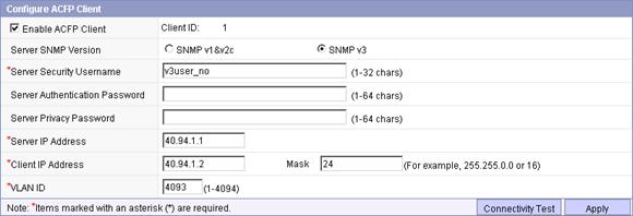
b. Select Enable ACFP Client, select the SNMP version SNMPv3, enter the server security username v3user_no, enter the server IP address 40.94.1.1, the client IP address 40.94.1.2, the mask 24, and the VLAN ID 4093.
a. Click Apply.
b. Click Connectivity Test to perform a connectivity test.
# Add security zone inbound:
a. Select System Management > Network Management > Security Zone from the navigation tree.
c. Click <<.
Figure 6 Adding security zone inbound
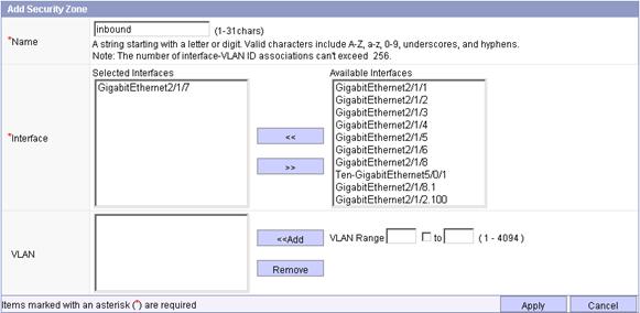
c. Enter the name inbound, select GigabitEthernet2/1/7 from the list, and click Add to add it into the Interface box.
a. Click Apply.
# Add security zone outbound:
a. Select System Management > Network Management > Security Zone from the navigation tree.
b. Click <<.
Figure 7 Creating security zone outbound

c. Enter the name outbound, select GigabitEthernet2/1/8 from the list, and click Add to add it into the Interface box.
a. Click Apply.
# Add segment 10:
a. Select System Management > Network Management > Segment Configuration from the navigation tree.
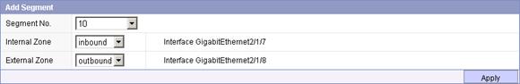
b. Select 10 from the Segment No. list.
a. Select inbound from the Internal Zone list.
b. Select outbound from the External Zone list.
c. Click Apply.
# Configure the collaboration policy and rules:
a. Select System Management > Network Management > ACFP Policy from the navigation tree.
d. Click Create Policy.
Figure 9 Configuring collaboration policy
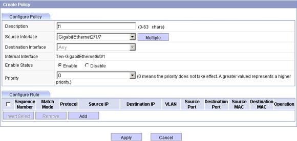
c. Enter the description t1.
a. Select GigabitEthernet2/1/7 from the Source Interface list.
b. Select the Enable option.
c. Select 0 from the Priority list.
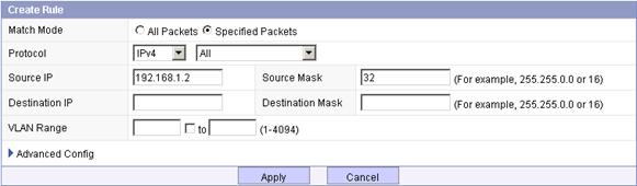
# Add rule 1:
a. Click Add on the Configure Rule tab as shown in Figure 9. After the page for creating a rule pops up, perform the following configuration as shown in Figure 10.
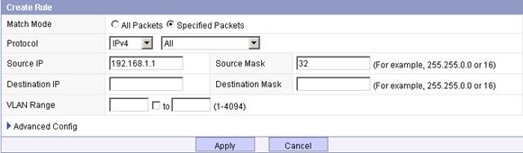
b. Select the Specified Packets option.
a. Select All from the Protocol list.
b. Enter the source IP address 192.168.1.1.
c. Enter the source mask 32.
d. Click Apply.
# Create rule 2:
a. Click Add on the Configure Rule tab as shown in Figure 9.
b. Select the Specified Packets option.
a. Select All from the Protocol list.
b. Enter the source IP address 192.168.1.2.
c. Enter the source mask 32.
d. Click Apply.
# Configure ACFP filtering rule 1:
a. Select Bandwidth Management > Bandwidth Policies from the navigation tree.
e. Click Add.
Figure 12 Creating a policy application
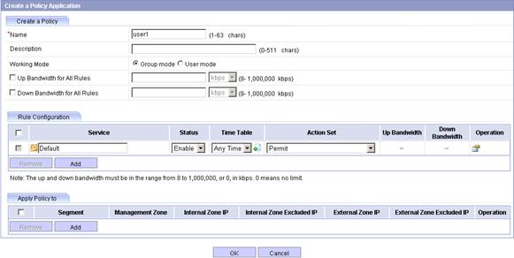
c. Enter the name user1, select the working mode Group mode, and select Permit from the Action Set list.
a. Click Add to add a new entry in the policy application list.
Figure 13 Policy application range
e. Click ![]() .
.
The page for adding IP address group pops up.
Figure 14 Adding IP address group 1
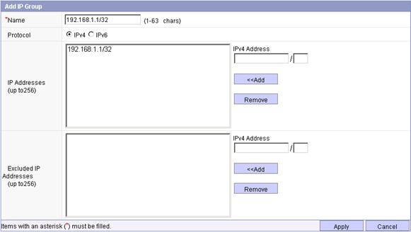
f. Enter the name 192.168.1.1/32, select the protocol IPv4, enter the IPv4 address 192.168.1.1/32, click <<Add to add the address to the IP address box, and click Apply.
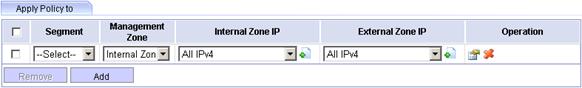
a. In the policy application range page, click ![]() .
.
Figure 15 Advanced configuration
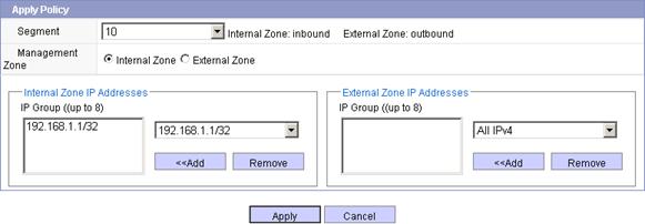
h. Select 10 from the Segment list, select the Internal Zone option, select IP address 192.168.1.1/32 from the Internal Zone IP Addresses area, and click Apply.
a. After finishing the above configuration, click OK on the page shown in Figure 12.
# Configure ACFP filtering rule 2:
a. Select Bandwidth Management > Bandwidth Policies from the navigation tree.
b. Click Add.
Figure 16 Creating a policy application
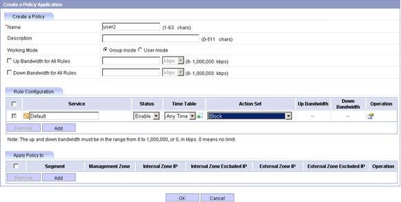
c. Enter the name user2, select the working mode Group mode, and select Block from the Action Set list.
a. Click Add to add a new entry in the policy application list.
Figure 17 Policy application range
e. Click ![]() .
.
The page for adding IP address group pops up.
Figure 18 Adding IP address group 2
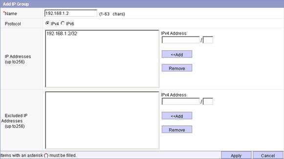
f. Enter the name 192.168.1.2/32, select the protocol IPv4, enter the IPv4 address 192.168.1.2/32, and click <<Add to add the address to the IP address box.
a. Click Apply.
b. In the policy application range page, click ![]() .
.
Figure 19 Advanced configuration
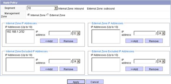
i. Select 10 from the Segment list, select the Internal Zone option, select IP address 192.168.1.2/32 from the Internal Zone IP Addresses area, and click Apply.
j. After finishing the above configuration, click OK on the page shown in Figure 12.
# Activate configurations:
After you finish the above configuration, the page jumps to the page as shown in Figure 20.
Figure 20 Activating configurations
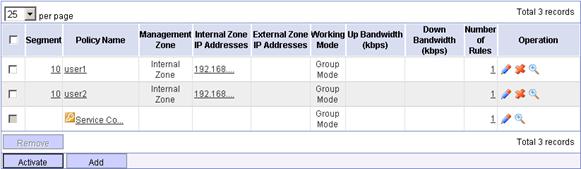
a. Click Activate.
A confirm dialog box pops up.
b. Click OK to activate the configuration.
3. Verify the configuration:
Use the ping command to verify the connectivity between Host A and Host C, Host B and Host C. The test results show that Host A can ping Host C but Host B cannot.
|
|
CAUTION: Set the ACL rule length limit mode to 3 or 4 with the acl mode command before you creating an ACFP policy rule of IPv6 protocol. For more information about ACL rule length limit mode, see ACL and QoS Command Reference. |