- Table of Contents
-
- 12-Network Management and Monitoring Configuration Guide
- 00-Preface
- 01-System Maintenance and Debugging Configuration
- 02-NQA Configuration
- 03-NTP Configuration
- 04-Clock Monitoring Configuration
- 05-IPC Configuration
- 06-SNMP Configuration
- 07-RMON Configuration
- 08-Sampler Configuration
- 09-Mirroring Configuration
- 10-NetStream Configuration
- 11-IPv6 NetStream Configuration
- 12-Protocol Packet Statistics Configuration
- 13-Information Center Configuration
- 14-Flow Logging Configuration
- Related Documents
-
| Title | Size | Download |
|---|---|---|
| 09-Mirroring Configuration | 210.55 KB |
Contents
Terminologies of port mirroring
Port mirroring classification and implementation
Configuring local port mirroring
Configuring remote port mirroring
Configuring a remote source mirroring group
Configuring a remote destination mirroring group
Displaying and maintaining port mirroring
Port mirroring configuration examples
Local port mirroring configuration example (in source port mode)
Layer 2 remote port mirroring configuration example (reflector port configurable)
Displaying and maintaining traffic mirroring
Traffic mirroring configuration example
|
|
NOTE: In this document, SPC cards refer to the cards prefixed with SPC, for example, SPC-GT48L. SPE cards refer to the cards prefixed with SPE, for example, SPE-1020-E-II. |
Introduction
Port mirroring refers to the process of copying the packets that pass through a specified port to the monitor port connecting to a monitoring device for packet analysis.
Terminologies of port mirroring
Mirroring source
The mirroring source can be one or more monitored ports. Packets (called mirrored packets) passing through them are copied to a port connecting to a monitoring device for packet analysis. Such a port is called a source port and the device where the port resides is called a source device.
Mirroring destination
The mirroring destination is the destination port (also known as the monitor port) of mirrored packets and connects to the data monitoring device. The device where the monitor port resides is called the destination device. The monitor port forwards mirrored packets to its connecting monitoring device.
|
|
NOTE: A monitor port may receive multiple duplicates of a packet in some cases because it can monitor multiple mirroring sources. For example, assume that Port 1 is monitoring bidirectional traffic on Port 2 and Port 3 on the same device. If a packet travels from Port 2 to Port 3, two duplicates of the packet will be received on Port 1. |
Mirroring direction
The mirroring direction indicates that the inbound, outbound, or bidirectional traffic can be copied on a mirroring source.
· Inbound—Copies packets received on a mirroring source.
· Outbound—Copies packets sent out a mirroring source.
· Bidirectional—Copies packets both received and sent on a mirroring source.
Mirroring group
Port mirroring is implemented through mirroring groups, which fall into local, remote source, and remote destination mirroring groups. For more information about the mirroring groups, see “Port mirroring classification and implementation.”
Reflector port, egress port, and remote probe VLAN
A reflector port, remote probe VLAN, and an egress port are used for Layer 2 remote port mirroring. The remote probe VLAN specially transmits mirrored packets to the destination device. Both the reflector port and egress port reside on a source device and send mirrored packets to the remote probe VLAN. The egress port must belong to the remote probe VLAN while the reflector port may not. For more information about the source device, destination device, reflector port, egress port, and remote probe VLAN, see “Port mirroring classification and implementation.”
Port mirroring classification and implementation
According to the locations of the mirroring source and the mirroring destination, port mirroring falls into local port mirroring and remote port mirroring.
Local port mirroring
In local port mirroring, the mirroring source and the mirroring destination are on the same device. A mirroring group that contains the mirroring source and the mirroring destination on the device is called a local mirroring group.
Figure 1 Local port mirroring implementation
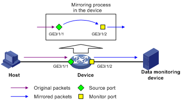
As shown in Figure 1, the source port GigabitEthernet 3/1/1 and monitor port GigabitEthernet 3/1/2 reside on the same device. Packets of GigabitEthernet 3/1/1 are copied to GigabitEthernet 3/1/2, which then forwards the packets to the data monitoring device for analysis.
Remote port mirroring
In remote port mirroring, the mirroring source and the mirroring destination reside on different devices and in different mirroring groups. The mirroring group that contains the mirroring source or the mirroring destination is called a remote source/destination group. The devices between the source devices and destination device are intermediate devices.
Remote port mirroring falls into Layer 2 and Layer 3 remote port mirroring.
· Layer 2 remote port mirroring—In Layer 2 remote port mirroring, the mirroring source and the mirroring destination are located on different devices on a same Layer 2 network.
· Layer 3 remote port mirroring—In Layer 3 remote port mirroring, the mirroring source and the mirroring destination are separated by IP networks. The router does not support Layer 3 remote port mirroring.
|
|
NOTE: · Layer 2 remote port mirroring can be implemented when a fixed reflector port, configurable reflector port, or configurable egress port is available on the source device. The configuration method when either of the first two ports is available on the source device is called reflector port method. You must configure a reflector port on the source device that has a configurable reflector port. The router only supports configurable reflector ports. · Layer 2 remote port mirroring cannot be implemented on an SPE card when a configurable reflector port is available on the source device. |
Figure 2 Layer 2 remote port mirroring implementation (with a reflector port)
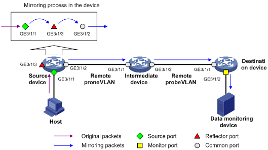
On the network shown in Figure 2, the source device copies the packets received on the source port GigabitEthernet 3/1/1 to the reflector port GigabitEthernet 3/1/3. GigabitEthernet 3/1/3 broadcasts the packets in the remote probe VLAN and the intermediate device in the VLAN transmits the packets to the destination device. When receiving these mirrored packets, the destination device compares their VLAN IDs to the ID of the remote probe VLAN configured in the remote destination group. If the VLAN IDs of these mirrored packets match the remote probe VLAN ID, the device forwards them to the data monitoring device through the monitor port.
Configuring local port mirroring
Configuring local mirroring is to configure local mirroring groups.
A local mirroring group comprises one or multiple mirroring ports and one monitor port that are located on the same router.
To configure local port mirroring:
|
Step |
Command |
Remarks |
|
|
|
1. Enter system view. |
system-view |
N/A |
|
|
|
2. Create a local mirroring group. |
mirroring-group group-id local |
N/A |
|
|
|
3. Add ports to the port mirroring group as mirroring ports. |
·
(Approach I) In system
view:: · (Approach II) In interface view: a. interface interface-type interface-number b. [ mirroring-group group-id ] mirroring-port { both | inbound | outbound } c. quit |
Use either approach. You can add ports to a port mirroring group as mirroring ports in either system view or interface view. In system view, you can add multiple ports to a port mirroring group at a time. While in interface view, you can add only the current port to a port mirroring group. |
|
|
|
4. Add a port to the mirroring group as the monitor port. |
·
(Approach I) In system
view: · (Approach II) In interface view: a. interface interface-type interface-number b. [ mirroring-group group-id ] monitor-port |
Use either approach. You can add a monitor port to a port mirroring group in either system view or interface view. They achieve the same purpose. |
||
|
|
NOTE: · A local mirroring group is effective only when it has both mirroring ports and the monitor port configured. · To make sure that the mirroring function works properly, do not enable STP on the monitor port of a mirroring group. · A port mirroring group can contain multiple mirroring ports and only one monitor port. · A port can belong to only one port mirroring group. |
Configuring remote port mirroring
|
|
NOTE: · If the GARP VLAN Registration Protocol (GVRP) is enabled, GVRP may register the remote probe VLAN to unexpected ports, resulting in undesired duplicates. For more information about GVRP, see Layer 2—LAN Switching Configuration Guide. · The router supports remote mirroring only when the system working mode is SPC or SPE. |
Configuration prerequisites
Before configuring remote port mirroring, create a static VLAN to be configured as the remote probe VLAN later.
|
|
CAUTION: · The remote source mirroring group on the source device and the remote destination mirroring group on the destination device must use the same remote probe VLAN. · To make sure that the mirroring function works properly, do not connect a network cable to the reflector port, and disable these functions on the port: STP, IGMP snooping, static ARP, and MAC address learning. |
Configuring a remote source mirroring group
To configure a remote source mirroring group:
|
Step |
Command |
Remarks |
|
1. Enter system view. |
system-view |
N/A |
|
2. Create a remote source mirroring group. |
mirroring-group group-id remote-source |
N/A |
|
3. Add ports to the mirroring group as mirroring ports. |
·
(Approach I) In system
view: · (Approach II) In interface view: a. interface interface-type interface-number b. [ mirroring-group group-id ] mirroring-port { both | inbound | outbound } c. quit. |
Use either approach. You can add ports to a source port mirroring group in either system view or interface view. They achieve the same purpose. |
|
4. Add a reflector port for a mirroring group. |
·
(Approach I) In system
view: · (Approach II) In Ethernet interface view: a. interface interface-type interface-number b. mirroring-group group-id reflector-port c. quit |
Use either approach. |
|
5. Configure the remote probe VLAN for the mirroring group. |
mirroring-group group-id remote-probe vlan rprobe-vlan-id |
N/A |
|
|
NOTE: · To avoid router performance degradation, do not add mirroring ports to the remote probe VLAN. · Only existing static VLANs can be configured as remote probe VLANs. To remove a VLAN operating as a remote probe VLAN, you need to restore it to a normal VLAN first. A remote port mirroring group gets invalid if the corresponding remote probe VLAN is removed. · Use a remote probe VLAN for remote port mirroring only. · A port can belong to only one port mirroring group. A VLAN can be the remote probe VLAN of only one port mirroring group. · To make sure that the mirroring function works properly, do not enable STP on the monitor port. · You can configure a reflector port only when the router works in SPC mode. |
Configuring a remote destination mirroring group
To configure a remote destination mirroring group:
|
Step |
Command |
Remarks |
|
1. Enter system view. |
system-view |
N/A |
|
2. Create a remote destination mirroring group. |
mirroring-group group-id remote-destination |
N/A |
|
3. Configure the remote probe VLAN for the mirroring group. |
mirroring-group group-id remote-probe vlan rprobe-vlan-id |
N/A |
|
4. Add a port to the port mirroring group as the monitor port. |
·
In system view: · In interface view: a. interface interface-type interface-number b. [ mirroring-group group-id ] monitor-port c. quit |
Use either approach, which leads to the same result. |
|
5. Enter destination interface view. |
interface interface-type interface-number |
N/A |
|
6. Add the port to the remote probe VLAN. |
·
The port is an access port: ·
The port is a trunk port: ·
The port is a hybrid port: |
Use any of these three approaches according to the port type. |
Displaying and maintaining port mirroring
|
Task |
Command |
Remarks |
|
Display the configuration of a port mirroring group. |
display mirroring-group { group-id | all | local | remote-destination | remote-source } [ | { begin | exclude | include } regular-expression ] |
Available in any view |
Port mirroring configuration examples
Local port mirroring configuration example (in source port mode)
Network requirements
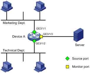
On a network shown in Figure 3:
· Device A connects to the marketing department through GigabitEthernet 3/1/1 and to the technical department through GigabitEthernet 3/1/2. It connects to the server through GigabitEthernet 3/1/3.
· Configure local port mirroring in source port mode to enable the server to monitor the bidirectional traffic of the marketing department and the technical department.
Configuration procedure
1. Create a local mirroring group:
# Create local mirroring group 1.
<DeviceA> system-view
[DeviceA] mirroring-group 1 local
# Configure GigabitEthernet 3/1/1 and GigabitEthernet 3/1/2 as source ports and port GigabitEthernet 3/1/3 as the monitor port.
[DeviceA] mirroring-group 1 mirroring-port GigabitEthernet3/1/1 GigabitEthernet3/1/2 both
[DeviceA] mirroring-group 1 monitor-port GigabitEthernet3/1/3
# Disable the spanning tree feature on the monitor port GigabitEthernet 3/1/3.
[DeviceA] interface GigabitEthernet3/1/3
[DeviceA-GigabitEthernet3/1/3] undo stp enable
[DeviceA-GigabitEthernet3/1/3] quit
2. Verify the configuration:
# Display the configuration of all mirroring groups.
[DeviceA] display mirroring-group all
mirroring-group 1:
type: local
status: active
mirroring port:
GigabitEthernet3/1/1 both
GigabitEthernet3/1/2 both
monitor port: GigabitEthernet3/1/3
After the configurations are completed, you can monitor all the packets received and sent by the marketing department and the technical department on the server.
Layer 2 remote port mirroring configuration example (reflector port configurable)
|
|
NOTE: This configuration example is available only on SPC cards. |
Network requirements
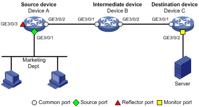
On the Layer 2 network shown in Figure 4:
· Device A connects to the marketing department through GigabitEthernet 3/0/1, and to the trunk port GigabitEthernet 3/0/1 of Device B through the trunk port GigabitEthernet 3/0/2; Device C connects to the server through GigabitEthernet 3/0/2, and to the trunk port GigabitEthernet 3/0/2 of Device B through the trunk port GigabitEthernet 3/0/1. Device A supports configurable reflector port configuration.
· Configure Layer 2 remote port mirroring to enable the server to monitor the bidirectional traffic of the marketing department.
Configuration procedure
1. Configure Device A (the source device):
# Create a remote source group.
<DeviceA> system-view
[DeviceA] mirroring-group 1 remote-source
# Create VLAN 2.
[DeviceA] vlan 2
[DeviceA-vlan2] quit
# Configure VLAN 2 as the remote probe VLAN, GigabitEthernet 3/0/1 as a source port, and GigabitEthernet 3/0/3 as the reflector port in the mirroring group.
[DeviceA] mirroring-group 1 remote-probe vlan 2
[DeviceA] mirroring-group 1 mirroring-port GigabitEthernet3/0/1 both
[DeviceA] mirroring-group 1 reflector-port GigabitEthernet3/0/3
# Configure GigabitEthernet 3/0/2 as a trunk port that permits the packets of VLAN 2 to pass through.
[DeviceA] interface GigabitEthernet3/0/2
[DeviceA-GigabitEthernet3/0/2] port link-type trunk
[DeviceA-GigabitEthernet3/0/2] port trunk permit vlan 2
[DeviceA-GigabitEthernet3/0/2] quit
# Disable the spanning tree feature on reflector port GigabitEthernet 3/0/3.
[DeviceA] interface GigabitEthernet3/0/3
[DeviceA-GigabitEthernet3/0/3] undo stp enable
[DeviceA-GigabitEthernet3/0/3] quit
2. Configure Device B (the intermediate device):
# Create VLAN 2.
<DeviceB> system-view
[DeviceB] vlan 2
[DeviceB-vlan2] quit
# Configure GigabitEthernet 3/0/1 as a trunk port that permits the packets of VLAN 2 to pass through.
[DeviceB] interface GigabitEthernet3/0/1
[DeviceB-GigabitEthernet3/0/1] port link-type trunk
[DeviceB-GigabitEthernet3/0/1] port trunk permit vlan 2
[DeviceB-GigabitEthernet3/0/1] quit
# Configure GigabitEthernet 3/0/2 as a trunk port that permits the packets of VLAN 2 to pass through.
[DeviceB] interface GigabitEthernet3/0/2
[DeviceB-GigabitEthernet3/0/2] port link-type trunk
[DeviceB-GigabitEthernet3/0/2] port trunk permit vlan 2
[DeviceB-GigabitEthernet3/0/2] quit
3. Configure Device C (the destination device):
# Configure GigabitEthernet 3/0/1 as a trunk port that permits the packets of VLAN 2 to pass through.
<DeviceC> system-view
[DeviceC] interface GigabitEthernet3/0/1
[DeviceC-GigabitEthernet3/0/1] port link-type trunk
[DeviceC-GigabitEthernet3/0/1] port trunk permit vlan 2
[DeviceC-GigabitEthernet3/0/1] quit
# Create a remote destination group.
[DeviceC] mirroring-group 1 remote-destination
# Create VLAN 2.
[DeviceC] vlan 2
[DeviceC-vlan2] quit
# Configure VLAN 2 as the remote probe VLAN of the mirroring group and GigabitEthernet 3/0/2 as the monitor port of the mirroring group, disable the spanning tree feature on GigabitEthernet 3/0/2, and assign the port to VLAN 2.
[DeviceC] mirroring-group 1 remote-probe vlan 2
[DeviceC] interface GigabitEthernet3/0/2
[DeviceC-GigabitEthernet3/0/2] mirroring-group 1 monitor-port
[DeviceC-GigabitEthernet3/0/2] undo stp enable
[DeviceC-GigabitEthernet3/0/2] port access vlan 2
[DeviceC-GigabitEthernet3/0/2] quit
4. Verify the configuration:
After the configurations are completed, you can monitor all the packets received and sent by the marketing department on the server.
Traffic mirroring overview
Traffic mirroring refers to the process of copying the specified packets to the specified destination for packet analysis and monitoring.
You can configure mirroring traffic to an interface, to the CPU, or to a VLAN.
· Mirroring traffic to an interface copies the matching packets on an interface to a destination interface.
· Mirroring traffic to the CPU copies the matching packets on an interface to a CPU (the CPU of the board where the traffic mirroring-enabled interface resides).
|
|
NOTE: · For more information about QoS policies, traffic classes, and traffic behaviors, see ACL and QoS Configuration Guide. · SPE cards support mirroring inbound and outbound traffic and SPC cards only support mirroring inbound traffic. |
Configuring traffic mirroring
To configure traffic mirroring, you must enter the view of an existing traffic behavior.
|
|
NOTE: In a traffic behavior, the action of mirroring traffic to an interface, the action of mirroring traffic to a CPU, and the action of mirroring traffic to a VLAN are mutually exclusive. |
Mirroring traffic to an interface
To mirror traffic to an interface:
|
Step |
Command |
|
1. Enter system view. |
system-view |
|
2. Enter traffic behavior view. |
traffic behavior behavior-name |
|
3. Specify the destination interface for traffic mirroring. |
mirror-to interface interface-type interface-number |
|
|
NOTE: Your configuration with the mirror-to interface command in a traffic behavior can overwrite the previous configuration in the traffic behavior, if any. |
Mirroring traffic to the CPU
To mirror traffic to the CPU:
|
Step |
Command |
Remarks |
|
1. Enter system view. |
system-view |
N/A |
|
2. Enter traffic behavior view. |
traffic behavior behavior-name |
N/A |
|
3. Mirror traffic to the CPU. |
mirror-to cpu |
The CPU refers to the CPU of the board where the interface resides. |
Mirroring traffic to a VLAN
To mirror traffic to a VLAN:
|
Step |
Command |
|
1. Enter system view. |
system-view |
|
2. Enter traffic behavior view. |
traffic behavior behavior-name |
|
3. Mirror traffic to a VLAN. |
mirror-to vlan vlan-id |
|
|
NOTE: · You can mirror traffic to an inexistent VLAN. When the VLAN is created and some ports join the VLAN, traffic mirroring for the VLAN takes effect automatically. · If the mirror-to vlan command is configured for the same traffic behavior for multiple times, the new configuration overwrites the previous one. |
Displaying and maintaining traffic mirroring
|
Task |
Command |
Remarks |
|
Display traffic behavior configuration information. |
display traffic behavior user-defined [ behavior-name ] [ | { begin | exclude | include } regular-expression ] |
Available in any view |
|
Display QoS policy configuration information. |
display qos policy user-defined [ policy-name [ classifier tcl-name ] ] [ | { begin | exclude | include } regular-expression ] |
Available in any view |
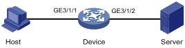
Traffic mirroring configuration example
Network requirements
As shown in Figure 5, configure the device to enable the server to analyze and monitor all the packets sent from Host.
Configuring the device
# Enter system view.
<Device> system-view
# Configure ACL 2000 to match all packets.
[Device] acl number 2000
[Device-acl-basic-2000] rule 1 permit
[Device-acl-basic-2000] quit
# Create traffic class classifier 1 and use ACL 2000 as the match criterion.
[Device] traffic classifier 1
[Device-classifier-1] if-match acl 2000
[Device-classifier-1] quit
# Create traffic behavior behavior 1 and configure the action of mirroring traffic to GigabitEthernet 3/0/2 for the traffic behavior.
[Device] traffic behavior 1
[Device-behavior-1] mirror-to interface GigabitEthernet 3/0/2
[Device-behavior-1] quit
# Create QoS policy policy 1, and associate traffic behavior behavior 1 with traffic class classifier 1.
[Device] qos policy 1
[Device-qospolicy-1] classifier 1 behavior 1
[Device-qospolicy-1] quit
# Apply the QoS policy in the inbound direction of GigabitEthernet 3/0/1.
[Device] interface GigabitEthernet 3/0/1
[Device-GigabitEthernet3/0/1] qos apply policy 1 inbound
After the configuration above, you can analyze and monitor all the packets that Host sends on Server.