- Table of Contents
-
- H3C WX3000 Series Unified Switches Switching Engine Configuration Guide-6W103
- 00-Preface
- 01-CLI Configuration
- 02-Login Configuration
- 03-Configuration File Management Configuration
- 04-VLAN Configuration
- 05-Auto Detect Configuration
- 06-Voice VLAN Configuration
- 07-GVRP Configuration
- 08-Basic Port Configuration
- 09-Link Aggregation Configuration
- 10-Port Isolation Configuration
- 11-Port Security-Port Binding Configuration
- 12-DLDP Configuration
- 13-MAC Address Table Management Configuration
- 14-MSTP Configuration
- 15-802.1x and System Guard Configuration
- 16-AAA Configuration
- 17-MAC Address Authentication Configuration
- 18-IP Address and Performance Configuration
- 19-DHCP Configuration
- 20-ACL Configuration
- 21-QoS-QoS Profile Configuration
- 22-Mirroring Configuration
- 23-ARP Configuration
- 24-SNMP-RMON Configuration
- 25-Multicast Configuration
- 26-NTP Configuration
- 27-SSH Configuration
- 28-File System Management Configuration
- 29-FTP-SFTP-TFTP Configuration
- 30-Information Center Configuration
- 31-System Maintenance and Debugging Configuration
- 32-VLAN-VPN Configuration
- 33-HWPing Configuration
- 34-DNS Configuration
- 35-Smart Link-Monitor Link Configuration
- 36-PoE-PoE Profile Configuration
- 37-Routing Protocol Configuration
- 38-UDP Helper Configuration
- 39-Acronyms
- 40-Index
- Related Documents
-
| Title | Size | Download |
|---|---|---|
| 02-Login Configuration | 327.33 KB |
1 Logging In to the Switching Engine
Logging In to the Switching Engine
Introduction to the User Interface
Common User Interface Configuration
Logging In to the Switching Engine Through OAP
Configuring the Management IP Address of the OAP Software System
Configuring the Management IP Address of the OAP Software System on the Switching Engine
Configuring the Management IP Address of the OAP Software System of the Access Control Engine
Resetting the OAP Software System
Telnet Configurations for Different Authentication Modes
Telnet Configuration with Authentication Mode Being None
Telnet Configuration with Authentication Mode Being Password
Telnet Configuration with Authentication Mode Being Scheme
Telnetting to the Switching Engine
Telnetting to the Switching Engine from a Terminal
Telnetting to the Switching Engine from the Access Control Engine
4 Logging In from the Web-Based Network Management System
Setting Up a Web Configuration Environment
Enabling/Disabling the WEB Server
Connection Establishment Using NMS
6 Configuring Source IP Address for Telnet Service Packets
Configuring Source IP Address for Telnet Service Packets
Displaying Source IP Address Configuration
Controlling Telnet Users by Source IP Addresses
Controlling Telnet Users by Source and Destination IP Addresses
Controlling Telnet Users by Source MAC Addresses
Controlling Network Management Users by Source IP Addresses
Controlling Network Management Users by Source IP Addresses
Controlling Web Users by Source IP Address
Controlling Web Users by Source IP Addresses
Disconnecting a Web User by Force
![]()
The sample output information in this manual was created on the WX3024. The output information on your device may vary.
Logging In to the Switching Engine
You can log in to the switching engine of the device in one of the following ways:
l Logging in through OAP
l Logging in locally or remotely through an Ethernet port by means of Telnet or SSH
l Logging in to the Web-based network management system
l Logging in through NMS (network management station)
Introduction to the User Interface
Supported User Interfaces
![]()
The auxiliary (AUX) port and the console port of the device are the same port (referred to as console port in the following part). You will be in the AUX user interface if you log in through this port.
The device supports two types of user interfaces: AUX and VTY.
l AUX user interface: A view when you log in through the console port.
l Virtual type terminal (VTY) user interface: A view when you log in through VTY. VTY port is a logical terminal line used when you access the device by means of Telnet or SSH.
Table 1-1 Description on user interface
|
User interface |
Applicable user |
Port used |
Description |
|
AUX |
Users logging in through the console port |
Console port |
Each device can accommodate one AUX user. |
|
VTY |
Telnet users and SSH users |
Ethernet port |
Each device can accommodate up to five VTY users. |
User Interface Index
Two kinds of user interface index exist: absolute user interface index and relative user interface index.
1) The absolute user interface indexes are as follows:
l The absolute AUX user interfaces is numbered 0.
l VTY user interface indexes follow AUX user interface indexes. The first absolute VTY user interface is numbered 1, the second is 2, and so on.
2) A relative user interface index can be obtained by appending a number to the identifier of a user interface type. It is generated by user interface type. The relative user interface indexes are as follows:
l AUX user interfaces is numbered 0.
l VTY user interfaces are numbered VTY0, VTY1, and so on.
Common User Interface Configuration
Follow these steps to configure common user interface:
|
To do… |
Use the command… |
Remarks |
|
Lock the current user interface |
lock |
Optional Execute this command in user view. A user interface is not locked by default. |
|
Specify to send messages to all user interfaces/a specified user interface |
send { all | number | type number } |
Optional Execute this command in user view. |
|
Free a user interface |
free user-interface [ type ] number |
Optional Execute this command in user view. |
|
Enter system view |
system-view |
— |
|
Set the banner |
header [ incoming | legal | login | shell ] text |
Optional By default, no banner is configured. |
|
Set a system name for the switching engine |
sysname string |
Optional By default, the system name is device. |
|
Enable copyright information displaying |
copyright-info enable |
Optional By default, copyright displaying is enabled. That is, the copy right information is displayed on the terminal after a user logs in successfully. |
|
Enter user interface view |
user-interface [ type ] first-number [ last-number ] |
— |
|
Display the information about the current user interface/all user interfaces |
display users [ all ] |
Optional You can execute the display command in any view. |
|
Display the physical attributes and configuration of the current/a specified user interface |
display user-interface [ type number | number ] |
|
|
Display the information about the current web users |
display web users |
OAP Overview
As an open software and hardware system, Open Application Architecture (OAA) provides a set of complete standard software and hardware interfaces. The third party vendors can develop products with special functions. These products can be compatible with each other as long as they conform to the OAA interface standards. Therefore the functions of single network product can be expanded and the users can get more benefits.
Open Application Platform (OAP) is a physical platform developed based on OAA. It can be an independent network device, or a board or program used as an extended part of a device. An OAP runs an independent operating system. You can load software such as security and voice in the operating system as needed.
Logging In to the Switching Engine Through OAP
You can log in to the access control engine through the console port on the device and perform the following configurations on the access control engine. Then, you can log in to the switching engine.
1) Execute the oap connect slot 0 command in user view of the access control engine to log in to the switching engine.
<device> oap connect slot 0
Connected to OAP!
2) Press Enter to enter user view of the switching engine.
<device_LSW>
![]()
l To distinguish between the access control engine and the switching engine, the name of the switching engine is changed to device_LSW here. In fact, the default name of the switching engine is device.
l You can press Ctrl+K to return to the command line interface of the access control engine.
Configuring the Management IP Address of the OAP Software System
In the OAA system of the device, the access control engine and the switching engine integrate together and function as one device. For the snmp UDP Domain-based network management station (NMS), however, the access control engine and the switching engine are independent SNMP agents. Physically, two agents are on the same managed object; while logically, they belong to two different systems, and they manage their own MIB objects on the access control engine and the switching engine separately. Therefore, when you use the NMS to manage the access control engine and the switching engine on the same interface, you must first obtain the management IP addresses of the two SNMP agents and obtain the link relationship between them, and then you can access the two agents. By default, the management IP address of an OAP module is not configured.
![]()
Before configuring the management IP address of the OAP software system, you must configure the same IP address at the engine side where the OAP software system resides; otherwise, the NMS cannot access the OAP software system by using the configured management IP address.
Follow these steps to configure the management IP address of the OAP software system:
|
To do… |
Use the command… |
Remarks |
|
Enter system view |
system-view |
— |
|
Configure the management IP address of an OAP module |
oap management-ip ip-address slot 0 |
Required Not configured by default. |
Configuring the Management IP Address of the OAP Software System on the Switching Engine
1) Configure the management IP address of the OAP software system on the switching engine side.
<device_LSW> system-view
[device_LSW] interface vlan-interface 1
[device_LSW-Vlan-interface1] ip address 192.168.0.2 24
Press Ctrl+K to return to the command line operating interface of the access control engine.
2) Configure the management IP address of the SNMP agent on the access control engine.
<device> system-view
[device] oap management-ip 192.168.0.2 slot 0
Configuring the Management IP Address of the OAP Software System of the Access Control Engine
1) Configure the management IP address of the OAP software system on the access control engine side.
<device> system-view
[device] interface Vlan-interface 1
[device-Vlan-interface1] ip address 192.168.0.1 24
2) Log in to the switching engine, and configure the management IP address of the SNMP agent on the switching engine.
<device> oap connect slot 0
Connected to OAP!
<device_LSW> system-view
[device_LSW] oap management-ip 192.168.0.1 slot 0
Resetting the OAP Software System
If the operating system works abnormally or is under other anomalies, you can reset the OAP software system.
Follow these steps to reset the OAP software system:
|
To do… |
Use the command… |
Remarks |
|
Reset the OAP software system |
oap reboot slot 0 |
Required Available in user view |
![]()
The reset operation may cause data loss and service interruption. Therefore, before resetting the OAP software system, you need to save the data on the operating system to avoid service interruption and hardware data loss.
Introduction
The device supports Telnet. You can manage and maintain the switching engine remotely by Telnetting to the switching engine.
To log in to the switching engine through Telnet, the corresponding configuration is required on both the switching engine and the Telnet terminal.
You can also log in to the switching engine through SSH. SSH is a secure shell added to Telnet. Refer to SSH in H3C WX3000 Series Unified Switches Switching Engine Configuration Guide for related information.
Table 3-1 Requirements for Telnetting to the switching engine
|
Item |
Requirement |
|
Switching engine |
The IP address is configured for the VLAN of the switching engine, and the route between the switching engine and the Telnet terminal is reachable. (Refer to IP Address and Performance and Routing Protocol in H3C WX3000 Series Unified Switches Switching Engine Configuration Guide for more.) |
|
The authentication mode and other settings are configured. Refer to Table 3-2 and Table 3-3. |
|
|
Telnet terminal |
Telnet is running. |
|
The IP address of the VLAN of the switching engine is available. |
Common Configuration
Table 3-2 lists the common Telnet configuration.
Table 3-2 Common Telnet configuration
|
Configuration |
Description |
|
|
VTY user interface configuration |
Configure the command level available to users logging in to the VTY user interface |
Optional By default, commands of level 0 are available to users logging in to a VTY user interface. |
|
Configure the protocols the user interface supports |
Optional By default, Telnet and SSH protocol are supported. |
|
|
Set the commands to be executed automatically after a user log in to the user interface successfully |
Optional By default, no command is executed automatically after a user logs into the VTY user interface. |
|
|
VTY terminal configuration |
Make terminal services available |
Optional By default, terminal services are available in all user interfaces |
|
Set the maximum number of lines the screen can contain |
Optional By default, the screen can contain up to 24 lines. |
|
|
Set history command buffer size |
Optional By default, the history command buffer can contain up to 10 commands. |
|
|
Set the timeout time of a user interface |
Optional The default timeout time is 10 minutes. |
|
Telnet Configurations for Different Authentication Modes
Table 3-3 lists Telnet configurations for different authentication modes.
Table 3-3 Telnet configurations for different authentication modes
|
Authentication mode |
Telnet configuration |
Description |
|
|
None |
Perform common configuration |
Perform common Telnet configuration |
Optional Refer to Table 3-2. |
|
Password |
Configure the password |
Configure the password for local authentication |
Required |
|
Perform common configuration |
Perform common Telnet configuration |
Optional Refer to Table 3-2. |
|
|
Scheme |
Specify to perform local authentication or remote RADIUS authentication |
AAA configuration specifies whether to perform local authentication or RADIUS authentication |
Optional Local authentication is performed by default. Refer to AAA in H3C WX3000 Series Unified Switches Switching Engine Configuration Guide for more. |
|
Configure user name and password |
Configure user names and passwords for local/RADIUS users |
Required l The user name and password of a local user are configured on the switching engine. l The user name and password of a remote user are configured on the RADIUS server. Refer to user manual of RADIUS server for more. |
|
|
Manage VTY users |
Set service type for VTY users |
Required |
|
|
Perform common configuration |
Perform common Telnet configuration |
Optional Refer to Table 3-2. |
|
![]()
To improve security and prevent attacks to the unused Sockets, TCP 23 and TCP 22, ports for Telnet and SSH services respectively, will be enabled or disabled after corresponding configurations.
l If the authentication mode is none, TCP 23 will be enabled, and TCP 22 will be disabled.
l If the authentication mode is password, and the corresponding password has been set, TCP 23 will be enabled, and TCP 22 will be disabled.
l If the authentication mode is scheme, there are three scenarios: when the supported protocol is specified as telnet, TCP 23 will be enabled; when the supported protocol is specified as ssh, TCP 22 will be enabled; when the supported protocol is specified as all, both the TCP 23 and TCP 22 port will be enabled.
Telnet Configuration with Authentication Mode Being None
Configuration Procedure
Follow these steps to perform Telnet configuration with the authentication mode being none:
|
To do… |
Use the command… |
Remarks |
|
Enter system view |
system-view |
— |
|
Enter one or more VTY user interface views |
user-interface vty first-number [ last-number ] |
— |
|
Configure not to authenticate users logging in to VTY user interfaces |
authentication-mode none |
Required By default, VTY users are authenticated after logging in. |
|
Configure the command level available to users logging in to VTY user interface |
user privilege level level |
Optional By default, commands of level 0 are available to users logging in to VTY user interfaces. |
|
Configure the protocols to be supported by the VTY user interface |
protocol inbound { all | ssh | telnet } |
Optional By default, both Telnet protocol and SSH protocol are supported. |
|
Set the commands to be executed automatically after a user login to the user interface successfully |
auto-execute command text |
Optional By default, no command is executed automatically after a user logs in to the VTY user interface. |
|
Make terminal services available |
shell |
Optional By default, terminal services are available in all user interfaces. |
|
Set the maximum number of lines the screen can contain |
screen-length screen-length |
Optional By default, the screen can contain up to 24 lines. You can use the screen-length 0 command to disable the function to display information in pages. |
|
Set the history command buffer size |
history-command max-size value |
Optional The default history command buffer size is 10. That is, a history command buffer can store up to 10 commands by default. |
|
Set the timeout time of the VTY user interface |
idle-timeout minutes [ seconds ] |
Optional The default timeout time of a user interface is 10 minutes. With the timeout time being 10 minutes, the connection to a user interface is terminated if no operation is performed in the user interface within 10 minutes. You can use the idle-timeout 0 command to disable the timeout function. |
Note that if you configure not to authenticate the users, the command level available to users logging in to the switching engine depends on the user privilege level level command
Configuration Example
Network requirements
As shown in Figure 3-1, assume current user logs in using the oap connect slot 0 command, and the user level is set to the manage level (level 3). Perform the following configurations for users logging in through VTY 0 using Telnet.
l Do not authenticate the users.
l Commands of level 2 are available to the users.
l Telnet protocol is supported.
l The screen can contain up to 30 lines.
l The history command buffer can contain up to 20 commands.
l The timeout time of VTY 0 is 6 minutes.
Figure 3-1 Network diagram for Telnet configuration (with the authentication mode being none)

Configuration procedure
# Enter system view.
<device> system-view
# Enter VTY 0 user interface view.
[device] user-interface vty 0
# Configure not to authenticate Telnet users logging in through VTY 0.
[device-ui-vty0] authentication-mode none
# Specify commands of level 2 are available to users logging in through VTY 0.
[device-ui-vty0] user privilege level 2
# Configure Telnet protocol is supported.
[device-ui-vty0] protocol inbound telnet
# Set the maximum number of lines the screen can contain to 30.
[device-ui-vty0] screen-length 30
# Set the maximum number of commands the history command buffer can store to 20.
[device-ui-vty0] history-command max-size 20
# Set the timeout time to 6 minutes.
[device-ui-vty0] idle-timeout 6
Telnet Configuration with Authentication Mode Being Password
Configuration Procedure
Follow these steps to perform Telnet configuration with the authentication mode being password:
|
To do… |
Use the command… |
Remarks |
|
Enter system view |
system-view |
— |
|
Enter one or more VTY user interface views |
user-interface vty first-number [ last-number ] |
— |
|
Configure to authenticate users logging in to VTY user interfaces using the local password |
authentication-mode password |
Required |
|
Set the local password |
set authentication password { cipher | simple } password |
Required |
|
Configure the command level available to users logging in to the user interface |
user privilege level level |
Optional By default, commands of level 0 are available to users logging in to VTY user interface. |
|
Configure the protocol to be supported by the user interface |
protocol inbound { all | ssh | telnet } |
Optional By default, both Telnet protocol and SSH protocol are supported. |
|
Set the commands to be executed automatically after a user login to the user interface successfully |
auto-execute command text |
Optional By default, no command is executed automatically after a user logs into the VTY user interface. |
|
Make terminal services available |
shell |
Optional By default, terminal services are available in all user interfaces. |
|
Set the maximum number of lines the screen can contain |
screen-length screen-length |
Optional By default, the screen can contain up to 24 lines. You can use the screen-length 0 command to disable the function to display information in pages. |
|
Set the history command buffer size |
history-command max-size value |
Optional The default history command buffer size is 10. That is, a history command buffer can store up to 10 commands by default. |
|
Set the timeout time of the user interface |
idle-timeout minutes [ seconds ] |
Optional The default timeout time of a user interface is 10 minutes. With the timeout time being 10 minutes, the connection to a user interface is terminated if no operation is performed in the user interface within 10 minutes. You can use the idle-timeout 0 command to disable the timeout function. |
Note that when the authentication mode is password, the command level available to users logging in to the user interface is determined by the user privilege level level command.
Configuration Example
Network requirements
As shown in Figure 3-2, assume current user logs in using the oap connect slot 0 command, and the user level is set to the manage level (level 3). Perform the following configurations for users logging in to VTY 0 using Telnet.
l Authenticate users using the local password.
l Set the local password to 123456 (in plain text).
l Commands of level 2 are available to the users.
l Telnet protocol is supported.
l The screen can contain up to 30 lines.
l The history command buffer can contain up to 20 commands.
l The timeout time of VTY 0 is 6 minutes.
Figure 3-2 Network diagram for Telnet configuration (with the authentication mode being password)
Configuration procedure
# Enter system view.
<device> system-view
# Enter VTY 0 user interface view.
[device] user-interface vty 0
# Configure to authenticate users logging in to VTY 0 using the password.
[device-ui-vty0] authentication-mode password
# Set the local password to 123456 (in plain text).
[device-ui-vty0] set authentication password simple 123456
# Specify commands of level 2 are available to users logging in to VTY 0.
[device-ui-vty0] user privilege level 2
# Configure Telnet protocol is supported.
[device-ui-vty0] protocol inbound telnet
# Set the maximum number of lines the screen can contain to 30.
[device-ui-vty0] screen-length 30
# Set the maximum number of commands the history command buffer can store to 20.
[device-ui-vty0] history-command max-size 20
# Set the timeout time to 6 minutes.
[device-ui-vty0] idle-timeout 6
Telnet Configuration with Authentication Mode Being Scheme
Configuration Procedure
Follow these steps to perform Telnet configuration with the authentication mode being scheme:
|
To do… |
Use the command… |
Remarks |
|
|
Enter system view |
system-view |
— |
|
|
Configure the authentication scheme |
Enter the default ISP domain view |
domain domain-name |
Optional By default, the local AAA scheme is applied. If you specify to apply the local AAA scheme, you need to perform the configuration concerning local user as well. If you specify to apply an existing scheme by providing the radius-scheme-name argument, you need to perform the following configuration as well: l Perform AAA and RADIUS configuration on the switching engine. (Refer to AAA in H3C WX3000 Series Unified Switches Switching Engine Configuration Guide for more.) l Configure the user name and password accordingly on the AAA server. (Refer to the user manual of the AAA server.) |
|
Configure the AAA scheme to be applied to the domain |
scheme { local | none | radius-scheme radius-scheme-name [ local ] | hwtacacs-scheme hwtacacs-scheme-name [ local ] } |
||
|
Quit to system view |
quit |
||
|
Create a local user and enter local user view |
local-user user-name |
No local user exists by default. |
|
|
Set the authentication password for the local user |
password { simple | cipher } password |
Required |
|
|
Specify the service type for VTY users |
service-type telnet [ level level ] |
Required |
|
|
Quit to system view |
quit |
— |
|
|
Enter one or more VTY user interface views |
user-interface vty first-number [ last-number ] |
— |
|
|
Configure to authenticate users locally or remotely |
authentication-mode scheme [ command- authorization ] |
Required The specified AAA scheme determines whether to authenticate users locally or remotely. Users are authenticated locally by default. |
|
|
Configure the command level available to users logging in to the user interface |
user privilege level level |
Optional By default, commands of level 0 are available to users logging in to the VTY user interfaces. |
|
|
Configure the supported protocol |
protocol inbound { all | ssh | telnet } |
Optional Both Telnet protocol and SSH protocol are supported by default. |
|
|
Set the commands to be executed automatically after a user login to the user interface successfully |
auto-execute command text |
Optional By default, no command is executed automatically after a user logs into the VTY user interface. |
|
|
Make terminal services available |
shell |
Optional Terminal services are available in all use interfaces by default. |
|
|
Set the maximum number of lines the screen can contain |
screen-length screen-length |
Optional By default, the screen can contain up to 24 lines. You can use the screen-length 0 command to disable the function to display information in pages. |
|
|
Set history command buffer size |
history-command max-size value |
Optional The default history command buffer size is 10. That is, a history command buffer can store up to 10 commands by default. |
|
|
Set the timeout time for the user interface |
idle-timeout minutes [ seconds ] |
Optional The default timeout time of a user interface is 10 minutes. With the timeout time being 10 minutes, the connection to a user interface is terminated if no operation is performed in the user interface within 10 minutes. You can use the idle-timeout 0 command to disable the timeout function. |
|
Note that if you configure to authenticate the users in the scheme mode, the command level available to the users logging in to the switching engine depends on the user privilege level level command and the service-type { ftp | lan-access | { ssh | telnet | terminal }* [ level level ] } command, as listed in Table 3-4.
Table 3-4 Determine the command level when users logging in to the switching engine are authenticated in the scheme mode
|
Scenario |
Command level |
||
|
Authentication mode |
User type |
Command |
|
|
authentication-mode scheme [ command-authorization ] |
VTY users that are AAA/RADIUS authenticated or locally authenticated |
The user privilege level level command is not executed, and the service-type command does not specify the available command level. |
Level 0 |
|
The user privilege level level command is not executed, and the service-type command specifies the available command level. |
Determined by the service-type command |
||
|
The user privilege level level command is executed, and the service-type command does not specify the available command level. |
Level 0 |
||
|
The user privilege level level command is executed, and the service-type command specifies the available command level. |
Determined by the service-type command |
||
|
VTY users that are authenticated in the RSA mode of SSH |
The user privilege level level command is not executed, and the service-type command does not specify the available command level. |
Level 0 |
|
|
The user privilege level level command is not executed, and the service-type command specifies the available command level. |
|||
|
The user privilege level level command is executed, and the service-type command does not specify the available command level. |
Determined by the user privilege level level command |
||
|
The user privilege level level command is executed, and the service-type command specifies the available command level. |
|||
|
VTY users that are authenticated in the password mode of SSH |
The user privilege level level command is not executed, and the service-type command does not specify the available command level. |
Level 0 |
|
|
The user privilege level level command is not executed, and the service-type command specifies the available command level. |
Determined by the service-type command |
||
|
The user privilege level level command is executed, and the service-type command does not specify the available command level. |
Level 0 |
||
|
The user privilege level level command is executed, and the service-type command specifies the available command level. |
Determined by the service-type command |
||
![]()
Refer to AAA and SSH in H3C WX3000 Series Unified Switches Switching Engine Configuration Guide for information about AAA, RADIUS, and SSH.
Configuration Example
Network requirements
As shown in Figure 3-3, assume a current user logs in using the oap connect slot 0 command and the user level is set to the manage level (level 3). Perform the following configurations for users logging in to VTY 0 using Telnet.
l Configure the local user name as guest.
l Set the authentication password of the local user to 123456 (in plain text).
l Set the service type of VTY users to Telnet and the command level to 2.
l Configure to authenticate users logging in to VTY 0 in scheme mode.
l Only Telnet protocol is supported in VTY 0.
l The screen can contain up to 30 lines.
l The history command buffer can store up to 20 commands.
l The timeout time of VTY 0 is 6 minutes.
Figure 3-3 Network diagram for Telnet configuration (with the authentication mode being scheme)
Configuration procedure
# Enter system view.
<device> system-view
# Create a local user named guest and enter local user view.
[device] local-user guest
# Set the authentication password of the local user to 123456 (in plain text).
[device-luser-guest] password simple 123456
# Set the service type to Telnet, Specify commands of level 2 are available to users logging in to VTY 0.
[device-luser-guest] service-type telnet level 2
[device-luser-guest] quit
# Enter VTY 0 user interface view.
[device] user-interface vty 0
# Configure to authenticate users logging in to VTY 0 in the scheme mode.
[device-ui-vty0] authentication-mode scheme
# Configure Telnet protocol is supported.
[device-ui-vty0] protocol inbound telnet
# Set the maximum number of lines the screen can contain to 30.
[device-ui-vty0] screen-length 30
# Set the maximum number of commands the history command buffer can store to 20.
[device-ui-vty0] history-command max-size 20
# Set the timeout time to 6 minutes.
[device-ui-vty0] idle-timeout 6
Telnetting to the Switching Engine
Telnetting to the Switching Engine from a Terminal
1) Assign an IP address to VLAN-interface 1 of the access control engine of the device (VLAN 1 is the default VLAN of the access control engine).
l Connect the serial port of your PC/terminal to the console port of the device, as shown in Figure 3-4.
Figure 3-4 Diagram for establishing connection to a console port
l Launch a terminal emulation utility (such as Terminal in Windows 3.X or HyperTerminal in Windows 95/Windows 98/Windows NT/Windows 2000/Windows XP) on the PC terminal, with the baud rate set to 9,600 bps, data bits set to 8, parity check set to none, and flow control set to none.
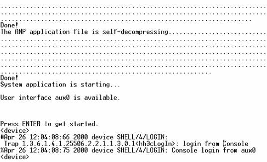
l Power on the device and press Enter as prompted. The prompt (such as <device>) appears, as shown in the following figure.
Figure 3-5 The terminal window
l Perform the following operations in the terminal window to assign IP address 202.38.160.90/24 to VLAN–interface 1 of the access control engine.
<device> system-view
[device] interface Vlan-interface 1
[device-Vlan-interface1] ip address 202.38.160.90 255.255.255.0
l Log in to the switching engine of the device using the oap connect slot 0 command.
<device>oap connect slot 0
Connected to OAP!
l Configure the IP address of VLAN-interface 1 of the switching engine of the device as 202.38.160.92/24.
<device_LSW> system-view
[device_LSW] interface Vlan-interface 1
[device_LSW-Vlan-interface1] ip address 202.38.160.92 255.255.255.0
![]()
To distinguish between the access control engine and the switching engine, the name of the switching engine is changed to device_LSW here. In fact, the default name of the switching engine is device.
2) Perform Telnet-related configuration on the switching engine. For details, refer to Telnet Configuration with Authentication Mode Being None, Telnet Configuration with Authentication Mode Being Password, and Telnet Configuration with Authentication Mode Being Scheme.
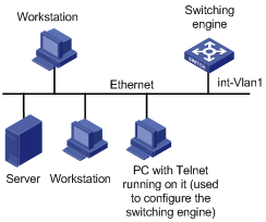
3) Connect your PC/terminal and the switching engine to an Ethernet, as shown in Figure 3-6. Make sure the port through which the switching engine is connected to the Ethernet belongs to VLAN 1 and the route between your PC and VLAN-interface 1 is reachable.
Figure 3-6 Network diagram for Telnet connection establishment
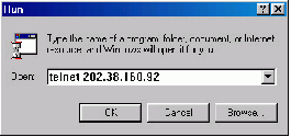
4) Launch Telnet on your PC, with the IP address of VLAN–interface 1 of the switching engine as the parameter, as shown in Figure 3-7.
5) If the password authentication mode is specified, enter the password when the Telnet window displays “Login authentication” and prompts for login password. The CLI prompt (such as <System_LSW>) appears if the password is correct. If all VTY user interfaces of the switching engine are in use, you will fail to establish the connection and see the message “All user interfaces are used, please try later!” The switching engine of the device can accommodate up to five Telnet connections at same time.
6) After successfully Telnetting to the switching engine, you can configure the switching engine or display the information about the switching engine by executing corresponding commands. You can also type ? at any time for help. Refer to the relevant parts in this manual for the information about the commands.
![]()
l A Telnet connection is terminated if you delete or modify the IP address of the VLAN interface in the Telnet session.
l By default, commands of level 0 are available to Telnet users authenticated by password. For the command hierarchy and command views, refer to CLI in H3C WX3000 Series Unified Switches Switching Engine Configuration Guide.
Telnetting to the Switching Engine from the Access Control Engine
You can Telnet to the switching engine from the access control engine. In this case, the access control engine operates as the client, and the switching engine operates as the server. If the interconnected Ethernet ports of the two engines are in the same LAN segment, make sure the IP addresses of the two management VLAN interfaces to which the two Ethernet ports belong are of the same network segment, or the route between the two VLAN interfaces is available.
As shown in Figure 3-8, after Telnetting to the access control engine (labeled as Telnet client), you can Telnet to the switching engine (labeled as Telnet server) by executing the telnet command and then configure it.
Figure 3-8 Network diagram for Telnetting to the switching engine from the access control engine

1) Perform Telnet-related configuration on the switching engine operating as the Telnet server. For details, refer to Telnet Configuration with Authentication Mode Being None, Telnet Configuration with Authentication Mode Being Password, and Telnet Configuration with Authentication Mode Being Scheme.
2) Telnet to the access control engine as the Telnet client.
3) Execute the following command on the access control engine operating as the Telnet client:
<device> telnet xxxx
Note that xxxx is the IP address or the host name of the access control engine operating as the Telnet server. You can use the ip host to assign a host name to the access control engine.
4) After successful login, the CLI prompt (such as <device>) appears. If all the VTY user interfaces of the switching engine are in use, you will fail to establish the connection and receive the message that says “All user interfaces are used, please try later!”.
5) After successfully Telnetting to the switching engine, you can configure the switching engine or display the information about the switching engine by executing corresponding commands. You can also type ? at any time for help. Refer to the subsequent chapters for the information about the commands.
When logging in from the Web-based network management system, go to these sections for information you are interested in:
l Setting Up a Web Configuration Environment
l Configuring the Login Banner
l Enabling/Disabling the WEB Server
Introduction
The device has a Web server built in. It enables you to log in to switching engine from a Web browser and then manage and maintain the device intuitively by interacting with the built-in Web server.
To log in to the built-in Web-based network management system of the switching engine, you need to perform the related configuration on both the switching engine and the PC operating as the network management terminal.
Table 4-1 Requirements for logging in to the switching engine from the Web-based network management system
|
Item |
Requirement |
|
Switching engine |
The VLAN interface of the switching engine is assigned an IP address, and the route between the switching engine and the Web network management terminal is reachable. (Refer to IP Address and Performance and Routing Protocol in H3C WX3000 Series Unified Switches Switching Engine Configuration Guide for related information.) |
|
The user name and password for logging in to the Web-based network management system are configured. |
|
|
PC operating as the network management terminal |
IE is available. |
|
The IP address of the VLAN interface of the switching engine, the user name, and the password are available. |
Setting Up a Web Configuration Environment
![]()
Your WX series access controller products were delivered with a factory default configuration. This configuration allows you to log into the built-in Web-based management system of the access controller product from a Web browser on a PC by inputting http://192.168.0.101 in the address bar of the browser. The default login username and password are both admin. After selecting your desired language, you can log in to the Web interface to make configuration. If you save your configuration, the device will boot with the configuration you made rather than the default at the next boot.
Log in to the switching engine with the oap connect slot 0 command and then perform the following operations.
1) Assign an IP address to VLAN-interface 1 of the switching engine (VLAN 1 is the default VLAN of the switching engine), and create a user account for the login user.
# Assign an IP address to the switching engine.
<device> system-view
[device] interface Vlan-interface 1
[device-Vlan-interface1] ip address 192.168.0.101 24
[device-Vlan-interface1] quit
# Create a Web user account, setting both the user name and the password to admin and the user level to 3 (manage level).
[device] local-user admin
[device-luser-admin] service-type telnet level 3
[device-luser-admin] password simple admin
[device-luser-admin] quit
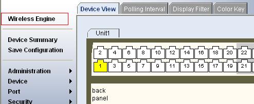
2) Configure the management IP address for the switching engine of the device (Optional).
# After configuring the IP address, you can go to the Web interface of the switching engine from the Web interface of the access controller engine by clicking the Wireless Engine button on the left upper part of the page, as shown in Figure 4-1. 192.168.0.100 is the management IP address of the switching engine, and slot 0 is the slot number of the switching engine.
[device] oap management-ip 192.168.0.100 slot 0
Figure 4-1 Web interface of the access controller engine
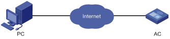
3) Set up a Web configuration environment, as shown in Figure 4-2.
Figure 4-2 Set up a Web configuration environment
4) Log in to the switching engine through IE. Launch IE on the Web-based network management terminal (your PC) and enter http://192.168.0.101 in the address bar. (Make sure a route is available between the Web-based network management terminal and the switching engine.)
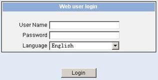
5) When the login authentication interface (as shown in Figure 4-3) appears, enter the user name and the password configured in step 2 and click Login to bring up the main page of the Web-based network management system.
Figure 4-3 The login page of the Web-based network management system
Configuring the Login Banner
Configuration Procedure
If a login banner is configured with the header command, when a user logs in through Web, the banner page is displayed before the user login authentication page. The contents of the banner page are the login banner information configured with the header command. Then, by clicking <Continue> on the banner page, the user can enter the user login authentication page, and enter the main page of the Web-based network management system after passing the authentication. If no login banner is configured by the header command, a user logging in through Web directly enters the user login authentication page.
Follow these steps to configure the login banner:
|
To do… |
Use the command… |
Remarks |
|
Enter system view |
system-view |
— |
|
Configure the banner to be displayed when a user logs in through Web |
header login text |
Required By default, no login banner is configured. |
Configuration Example
Network requirements
As shown in Figure 4-4,
l A user logs in to the switching engine through Web.
l The banner page is desired when a user logs in to the switching engine.
Figure 4-4 Network diagram for login banner configuration
Configuration Procedure
# Enter system view.
<device> system-view
# Configure the banner "Welcome" to be displayed when a user logs in to the switching engine through Web.
[device] header login %Welcome%
Assume that a route is available between the user terminal (the PC) and the switching engine. After the above-mentioned configuration, if you enter the IP address of the switching engine in the address bar of the browser running on the user terminal and press <Enter>, the browser will display the banner page, as shown in Figure 4-5.
Figure 4-5 Banner page displayed when a user logs in to the switching engine through Web
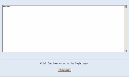
Click Continue to enter user login authentication page. You will enter the main page of the Web-based network management system if the authentication succeeds.
Enabling/Disabling the WEB Server
Follow these steps to enable/disable the WEB server:
|
To do… |
Use the command… |
Remarks |
|
Enter system view |
system-view |
— |
|
Enable the Web server |
ip http shutdown |
Required By default, the Web server is enabled. |
|
Disable the Web server |
undo ip http shutdown |
Required |
![]()
To improve security and prevent attack to the unused Sockets, TCP 80 port (which is for HTTP service) is enabled/disabled after the corresponding configuration.
l Enabling the Web server (by using the undo ip http shutdown command) opens TCP 80 port.
l Disabling the Web server (by using the ip http shutdown command) closes TCP 80 port.
Introduction
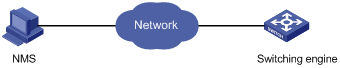
You can also log in to the switching engine from a network management station (NMS), and then configure and manage the switching engine through the agent module on the switch. Simple network management protocol (SNMP) is applied between the NMS and the agent. Refer to SNMP-RMON in H3C WX3000 Series Unified Switches Switching Engine Configuration Guide for related information.
To log in to the switching engine from an NMS, you need to perform related configuration on both the NMS and the switching engine.
Table 5-1 Requirements for logging in to the switching engine from an NMS
|
Item |
Requirement |
|
Switching engine |
The IP address of the VLAN interface of the switching engine is configured. The route between the NMS and the switching engine is reachable. (Refer to IP Address and Performance and Routing Protocol in H3C WX3000 Series Unified Switches Switching Engine Configuration Guide for related information.) |
|
The basic SNMP functions are configured. (Refer to SNMP-RMON in H3C WX3000 Series Unified Switches Switching Engine Configuration Guide for related information.) |
|
|
NMS |
The NMS is properly configured. (Refer to the user manual of your NMS for related information.) |
Connection Establishment Using NMS
Figure 5-1 Network diagram for logging in from an NMS
Overview
You can configure source IP address or source interface for the Telnet server and Telnet client. This provides a way to manage services and enhances security.
The source IP address specified for Telnet service packets is the IP address of a Loopback interface or VLAN interface. After you specify the IP address of a virtual Loopback interface or an unused VLAN interface as the source IP address of Telnet service packets, the IP address is used as the source IP address no matter which interface of the switching engine is used to transmit packets between the Telnet client and the Telnet server. This conceals the IP address of the actual interface used. As a result, external attacks are guarded and the security is improved. On the other hand, you can configure the Telnet server to accept only Telnet service packets with specific source IP addresses to make sure specific users can log in to the switching engine.
Configuring Source IP Address for Telnet Service Packets
This feature can be configured in either user view or system view. The configuration performed in user view takes effect for only the current session, while the configuration performed in system view takes effect for all the following sessions.
Configuration in user view
Follow these steps to configure a source IP address for service packets in user view:
|
To do… |
Use the command… |
Remarks |
|
Specify a source IP address for the Telnet client |
telnet remote-server source-ip ip-address |
Optional |
|
Specify a source interface for the Telnet client |
telnet remote-server source-interface interface-type interface-number |
Optional |
Configuration in system view
Follow these steps to configure a source IP address for service packets in system view:
|
To do… |
Use the command… |
Remarks |
|
Specify a source IP address for Telnet server |
telnet-server source-ip ip-address |
Optional |
|
Specify a source interface for Telnet server |
telnet-server source-interface interface-type interface-number |
Optional |
|
Specify source IP address for Telnet client |
telnet source-ip ip-address |
Optional |
|
Specify a source interface for Telnet client |
telnet source-interface interface-type interface-number |
Optional |
![]()
When configuring a source IP address for Telnet packets, ensure that:
l The source IP address must be one on the local device.
l The source interface must already exist.
l A reachable route is available between the source IP address (or the source interface) specified for the Telnet server or client and the Telnet client or server.
Displaying Source IP Address Configuration
|
To do… |
Use the command… |
Remarks |
|
Display the source IP address configured for the Telnet client |
display telnet source-ip |
Available in any view |
|
Display the source IP address configured for the Telnet server |
display telnet-server source-ip |
![]()
Refer to ACL in H3C WX3000 Series Unified Switches Switching Engine Configuration Guide for information about ACL.
Introduction
The switching engine provides ways to control different types of login users, as listed in Table 7-1.
Table 7-1 Ways to control different types of login users
|
Login mode |
Control method |
Implementation |
Reference |
|
Telnet |
By source IP address |
Through basic ACLs |
|
|
By source and destination IP address |
Through advanced ACLs |
Controlling Telnet Users by Source and Destination IP Addresses |
|
|
By source MAC address |
Through Layer 2 ACLs |
||
|
SNMP |
By source IP addresses |
Through basic ACLs |
|
|
WEB |
By source IP addresses |
Through basic ACLs |
|
|
Disconnect Web users by force |
By executing commands at CLI |
Controlling Telnet Users
Prerequisites
The controlling policy against Telnet users is determined, including the source IP addresses, destination IP addresses and source MAC addresses to be controlled and the controlling actions (permitting or denying).
Controlling Telnet Users by Source IP Addresses
Follow these steps to control Telnet users by source IP addresses:
|
To do… |
Use the command… |
Remarks |
|
Enter system view |
system-view |
— |
|
Create a basic ACL or enter basic ACL view |
acl number acl-number [ match-order { config | auto } ] |
As for the acl number command, the config keyword is specified by default. |
|
Define rules for the ACL |
rule [ rule-id ] { deny | permit } [ rule-string ] |
Required |
|
Quit to system view |
quit |
— |
|
Enter user interface view |
user-interface [ type ] first-number [ last-number ] |
— |
|
Apply the ACL to control Telnet users by source IP addresses |
acl acl-number { inbound | outbound } |
Required The inbound keyword specifies to filter the users trying to Telnet to the current switching engine. The outbound keyword specifies to filter users trying to Telnet to other devices from the current switching engine. |
Controlling Telnet Users by Source and Destination IP Addresses
Controlling Telnet users by source and destination IP addresses is achieved by applying advanced ACLs, which are numbered from 3000 to 3999.
Follow these steps to control Telnet users by source and destination IP addresses:
|
To do… |
Use the command… |
Remarks |
|
Enter system view |
system-view |
— |
|
Create an advanced ACL or enter advanced ACL view |
acl number acl-number [ match-order { config | auto } ] |
As for the acl number command, the config keyword is specified by default. |
|
Define rules for the ACL |
rule [ rule-id ] { deny | permit } protocol [ rule-string ] |
Required You can define rules as needed to filter by specific source and destination IP addresses. |
|
Quit to system view |
quit |
— |
|
Enter user interface view |
user-interface [ type ] first-number [ last-number ] |
— |
|
Apply the ACL to control Telnet users by specified source and destination IP addresses |
acl acl-number { inbound | outbound } |
Required The inbound keyword specifies to filter the users trying to Telnet to the current switching engine. The outbound keyword specifies to filter users trying to Telnet to other devices from the current switching engine. |
Controlling Telnet Users by Source MAC Addresses
Follow these steps to control Telnet users by source MAC addresses:
|
To do… |
Use the command… |
Remarks |
|
Enter system view |
system-view |
— |
|
Create or enter Layer 2 ACL view |
acl number acl-number |
— |
|
Define rules for the ACL |
rule [ rule-id ] { deny | permit } [ rule-string ] |
Required You can define rules as needed to filter by specific source MAC addresses. |
|
Quit to system view |
quit |
— |
|
Enter user interface view |
user-interface [ type ] first-number [ last-number ] |
— |
|
Apply the ACL to control Telnet users by specified source MAC addresses |
acl acl-number inbound |
Required By default, no ACL is applied for Telnet users. |
Configuration Example
Network requirements
As shown in Figure 7-1, only the Telnet users sourced from the IP address of 10.110.100.52 are permitted to access the switching engine.
Figure 7-1 Network diagram for controlling Telnet users using ACLs
Configuration procedure
# Define a basic ACL.
<device> system-view
[device] acl number 2000
[device-acl-basic-2000] rule 1 permit source 10.110.100.52 0
[device-acl-basic-2000] quit
# Apply the ACL.
[device] user-interface vty 0 4
[device-ui-vty0-4] acl 2000 inbound
Controlling Network Management Users by Source IP Addresses
You can manage the device through network management software. Network management users can access switching engines through SNMP.
You need to perform the following two operations to control network management users by source IP addresses.
l Defining an ACL
l Applying the ACL to control users accessing the switching engine through SNMP
Prerequisites
The controlling policy against network management users is determined, including the source IP addresses to be controlled and the controlling actions (permitting or denying).
Controlling Network Management Users by Source IP Addresses
Controlling network management users by source IP addresses is achieved by applying basic ACLs, which are numbered from 2000 to 2999.
Follow these steps to control network management users by source IP addresses:
|
To do… |
Use the command… |
Remarks |
|
Enter system view |
system-view |
— |
|
Create a basic ACL or enter basic ACL view |
acl number acl-number [ match-order { config | auto } ] |
Required As for the acl number command, the config keyword is specified by default. |
|
Define rules for the ACL |
rule [ rule-id ] { deny | permit } [ rule-string ] |
Required |
|
Quit to system view |
quit |
— |
|
Apply the ACL while configuring the SNMP community name |
snmp-agent community { read | write } community-name [ mib-view view-name | acl acl-number ]* |
Optional By default, SNMPv1 and SNMPv2c use community name to access. |
|
Apply the ACL while configuring the SNMP group name |
snmp-agent group { v1 | v2c } group-name [ read-view read-view ] [ write-view write-view ] [ notify-view notify-view ] [ acl acl-number ] snmp-agent group v3 group-name [ authentication | privacy ] [ read-view read-view ] [ write-view write-view ] [ notify-view notify-view ] [ acl acl-number ] |
Optional By default, the authentication mode and the encryption mode are configured as none for the group. |
|
Apply the ACL while configuring the SNMP user name |
snmp-agent usm-user { v1 | v2c } user-name group-name [ acl acl-number ] snmp-agent usm-user v3 user-name group-name [ cipher ] [ authentication-mode { md5 | sha } auth-password [ privacy-mode des56 priv-password ] [ acl acl-number ] |
Optional |
![]()
You can specify different ACLs while configuring the SNMP community name, SNMP group name, and SNMP user name.
As SNMP community name is a feature of SNMPv1 and SNMPv2c, the specified ACLs in the command that configures SNMP community names (the snmp-agent community command) take effect in the network management systems that adopt SNMPv1 or SNMPv2c.
Similarly, as SNMP group name and SNMP username name are a feature of SNMPv2c and the higher SNMP versions, the specified ACLs in the commands that configure SNMP group names and SNMP user names take effect in the network management systems that adopt SNMPv2c or higher SNMP versions. If you specify ACLs in the commands, the network management users are filtered by the SNMP group name and SNMP user name.
Configuration Example
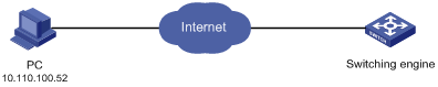
Network requirements
As shown in Figure 7-2, only SNMP users sourced from the IP addresses of 10.110.100.52 are permitted to log in to the switching engine.
Figure 7-2 Network diagram for controlling SNMP users using ACLs
Configuration procedure
# Define a basic ACL.
<device> system-view
[device] acl number 2000
[device-acl-basic-2000] rule 1 permit source 10.110.100.52 0
[device-acl-basic-2000] quit
# Apply the ACL to only permit SNMP users sourced from the IP addresses of 10.110.100.52 to access the switching engine.
[device] snmp-agent community read aaa acl 2000
[device] snmp-agent group v2c groupa acl 2000
[device] snmp-agent usm-user v2c usera groupa acl 2000
Controlling Web Users by Source IP Address
You can manage the device remotely through Web. Web users can access the switching engine through HTTP connections.
You need to perform the following two operations to control Web users by source IP addresses.
l Defining an ACL
l Applying the ACL to control Web users
Prerequisites
The controlling policy against Web users is determined, including the source IP addresses to be controlled and the controlling actions (permitting or denying).
Controlling Web Users by Source IP Addresses
Controlling Web users by source IP addresses is achieved by applying basic ACLs, which are numbered from 2000 to 2999.
Follow these steps to control Web users by source IP addresses:
|
To do… |
Use the command… |
Remarks |
|
Enter system view |
system-view |
— |
|
Create a basic ACL or enter basic ACL view |
acl number acl-number [ match-order { config | auto } ] |
As for the acl number command, the config keyword is specified by default. |
|
Define rules for the ACL |
rule [ rule-id ] { deny | permit } [ rule-string ] |
Required |
|
Quit to system view |
quit |
— |
|
Apply the ACL to control Web users |
ip http acl acl-number |
Optional By default, no ACL is applied for Web users. |
Disconnecting a Web User by Force
The administrator can disconnect a Web user by force using the related commands.
Follow these steps to disconnect a Web user by force:
|
To do… |
Use the command… |
Remarks |
|
Disconnect a Web user by force |
free web-users { all | user-id user-id | user-name user-name } |
Required Execute this command in user view. |
Configuration Example
Network requirements
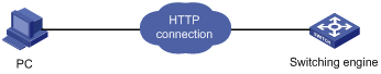
As shown in Figure 7-3, only the Web users sourced from the IP address of 10.110.100.52 are permitted to access the switching engine.
Figure 7-3 Network diagram for controlling Web users using ACLs
Configuration procedure
# Define a basic ACL.
<device> system-view
[device] acl number 2030
[device-acl-basic-2030] rule 1 permit source 10.110.100.52 0
[device-acl-basic-2030] quit
# Apply ACL 2030 to only permit the Web users sourced from the IP address of 10.110.100.52 to access the switching engine.
[device] ip http acl 2030
