- Released At: 18-12-2024
- Page Views:
- Downloads:
- Table of Contents
- Related Documents
-
|
|
|
|
|
PTP Technology White Paper |
|
|
|
|
Copyright © 2021 New H3C Technologies Co., Ltd. All rights reserved.
No part of this manual may be reproduced or transmitted in any form or by any means without prior written consent of New H3C Technologies Co., Ltd.
Except for the trademarks of New H3C Technologies Co., Ltd., any trademarks that may be mentioned in this document are the property of their respective owners.
This document provides generic technical information, some of which might not be applicable to your products.
The information in this document is subject to change without notice.
Contents
Comparison of time synchronization solutions
Determining the grandmaster clock
Establishing master-member/subordinate relationships
1588v2 frequency and phase synchronization
SyncE frequency synchronization + 1588v2 phase synchronization
Overview
Technical background
The normal operation of many services on the communication network requires network time synchronization. For time synchronization between devices on the network, you must keep the frequency and phase differences between devices within a reasonable error range. Wireless access services have the highest requirements for time synchronization. To prevent mobile phones from losing connection to the network when switching between base stations, the wireless base stations must be synchronized within certain frequency accuracy. The wireless communication technology such as CDMA or CDMA2000 requires not only frequency synchronization but also phase synchronization. In addition, the development of 5G technologies and application of new technologies such as carrier aggregation, multi-point cooperation, 5G ultra short frame structure, and high-precision positioning pose increasingly high requirements on time synchronization precision between base stations.
Precision Time Protocol (PTP) is a time synchronization protocol used for high-precision frequency and phase synchronization between network nodes. It provides time synchronization among devices with submicrosecond accuracy and is the optimal solution for scenarios such as broadcast and television networks, urban rail transit, and wireless access networks that require high-precision time synchronization.
Comparison of time synchronization solutions
The following table compares PTP and other time synchronization solutions, including Global Positioning System (GPS), Beidou Navigation Satellite System (BDS), Synchronous Ethernet (SyncE), and Network Time Protocol (NTP).
Table 1 Comparison of time synchronization solutions
|
Time sync solution |
Frequency sync |
Phase sync |
Sync accuracy |
Description |
|
GPS |
Supported |
Supported |
< 100 ns |
Uses electromagnetic waves to carry frequency and phase information and provide time synchronization. In recent years, the accuracy of GPS has been continuously improved. |
|
BDS |
Supported |
Supported |
ns level |
Uses electromagnetic waves to carry frequency and phase information and provide time synchronization. The BDS network is currently under construction and is expected to provide more ubiquitous, integrated, and smarter navigation, positioning, and timing services by 2035. |
|
SyncE |
Supported |
Not supported |
N/A |
Carries and restores frequency information over the Ethernet physical layer and provides frequency synchronization. |
|
NTP |
Not supported |
Supported |
ms level |
Uses NTP messages to transmit phase signals and provides phase synchronization. It is inadequate for scenarios such as wireless access networks that require microsecond-level time synchronization. |
|
PTP |
Supported |
Supported |
Sub-µs level to tens of nanoseconds |
Uses PTP messages to transmit frequency and phase information and combines hardware-based timestamping to deliver high-precision time synchronization. With the development of software and hardware technologies, PTP can bring time synchronization accuracy to tens of nanoseconds level or even better. |
PTP profiles
IEEE 1588 is the basic PTP protocol. It defines the high-precision clock synchronization principle and the message interaction and processing specifications on the network. It was initially used for industrial automation and is now mainly used on bridged local area networks. 1588 has two versions: 1588v1 and 1588v2. 1588v1 can provide time synchronization only with sub-millisecond accuracy, while 1588v2 can provide time synchronization accuracy to the sub-microsecond level and can achieve both phase and frequency synchronization. Currently, 1588v2 is more widely used than 1588v1.
Based on 1588, PTP protocols including IEEE 802.1AS, ITU-T G.8275.1, ITU-T G.8275.2, SMPTE ST 2059-2, and AES67-2015 were developed to adapt to different application scenarios. This document focuses on the implementation mechanism and application scenarios of 1588v2.
Table 2 Comparison of PTP profiles
|
PTP protocol |
Application scenarios |
Main features |
|
IEEE 1588v2 |
Applicable to various networking environments and can be customized, enhanced, or tailored as needed. |
· Algorithm for calculating master-member/subordinate relationships—Best Master Clock (BMC). · Delay measurement mechanisms—Request_Response and Peer Delay. · Transport of PTP messages—IEEE 802.3/Ethernet and UDP. |
|
IEEE 802.1AS |
Profile developed based on IEEE 1588-2008 for time synchronization over a virtual bridged LAN. It supports point-to-point full-duplex Ethernet, IEEE 802.11, and IEEE 802.3 EPON links. |
· Algorithm for calculating master-member/subordinate relationships—MSTP. · Delay measurement mechanisms—Peer Delay · Transport of PTP messages—IEEE 802.3/Ethernet. |
|
ITU-T G.8275.1 |
Telecom industry specific profile. |
· Algorithm for calculating master-member/subordinate relationships—Alternate BMCA. · Delay measurement mechanisms—Request_Response · Transport of PTP messages—IEEE 802.3/Ethernet. |
|
ITU-T G.8275.2 |
Telecom industry specific profile. |
· Algorithm for calculating master-member/subordinate relationships—Alternate BMCA. · Client-server architecture—The clients (member clock nodes) synchronize with the server (master clock node) by exchanging PTP messages. Layer 2 devices do not need to support PTP, because clients and the server communicate at Layer 3. · Delay measurement mechanisms—Request_Response. · Transport of PTP messages—UDP. |
|
SMPTE ST 2059-2 |
Time synchronization between audio and video devices in professional broadcast environment. |
· Algorithm for calculating master-member/subordinate relationships—BMC. · Delay measurement mechanisms—Request_Response and Peer Delay. · Transport of PTP messages—UDP. · Default protocol message transmission rate—Higher than 1588v2. |
|
AES67-2015 |
Time synchronization between broadcast, music production and postproduction devices. |
· Algorithm for calculating master-member/subordinate relationships—BMC. · Delay measurement mechanisms—Request_Response and Peer Delay. · Transport of PTP messages—UDP. · Default protocol message transmission rate—Higher than 1588v2. |
Time synchronization basics
Time synchronization includes frequency synchronization and phase synchronization. The synchronization requirements vary by networking environments.
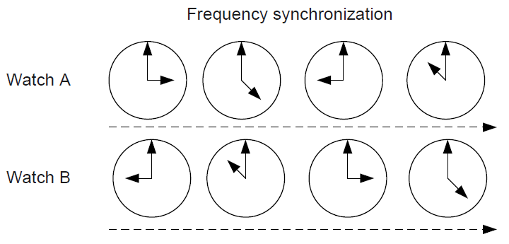
Frequency synchronization
Frequency synchronization is also called clock synchronization. If two signals are same in frequency or if they keep a constant phase difference, the two signals are frequency synchronized. As shown in Figure 1, the two watches have different time, but maintain a constant time difference (6 hours).
Figure 1 Frequency synchronization
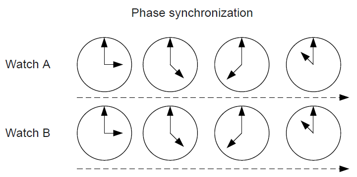
Phase synchronization
Phase synchronization is also called time synchronization. If two signals are same in frequency and phase (keep phase difference at 0), they are phase synchronized. As shown in Figure 2, the two watches have the same time at all times. Frequency synchronization is the prerequisite of phase synchronization.
Figure 2 Phase synchronization
1588v2 implementation
Network architecture
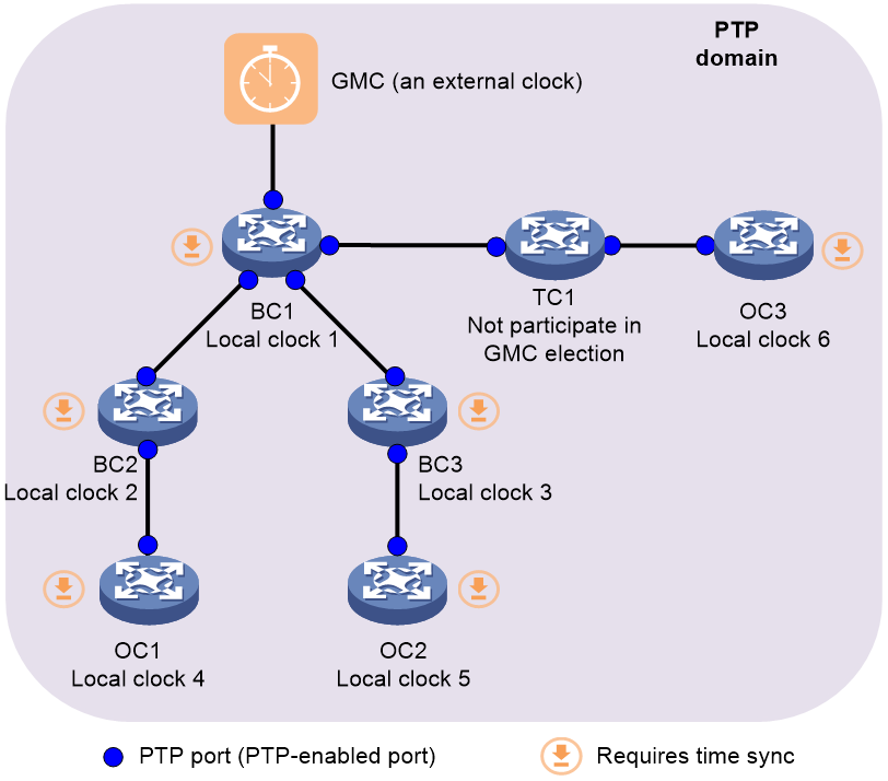
As shown in Figure 3, the 1588v2 network architecture includes the following key elements:
· PTP domain.
· Clock source.
· Grandmaster clock (GMC).
· Clock nodes.
Figure 3 1588v2 network architecture
PTP domain and multi-domain
A PTP domain is a network that runs a PTP profile.
To adapt to complex networking environments, Comware supports also PTP multi-domain, which allows you to assign devices to multiple PTP domains. The clock source, clock information, and time synchronization process of different PTP domains are independent of each other. When a device is added to multiple PTP domains, you must determine an optimal domain, and synchronize the time of the device with the clock source tracked by the optimal domain.
Clock source
The following clock sources are available for a device:
· Local clock source—38.88 MHz clock signals generated by a crystal oscillator inside the clock monitoring module.
· External clock source—Clock signals generated by an external clock device. The signals are received and sent by a 1PPS/ToD port on the MPU.
Grandmaster clock
Grandmaster clock (GMC) is the ultimate source of time for clock synchronization in a PTP domain. It can be manually specified, or elected automatically through the BMC algorithm. Only one GMC exists in a PTP domain, and all devices in the domain are synchronized with this clock.
Clock node
Devices participate in time synchronization in a PTP domain are called clock nodes. The following table describes the basic clock nodes defined in 1588v2. The locations of the clock nodes in the PTP domain are as shown in Figure 3.
Table 3 Clock nodes
|
Clock node |
PTP ports (PTP-enabled ports) |
Whether time synchronized |
Description |
|
OC |
1 |
Yes |
· Provides time synchronization signals as a clock source from one PTP port, or receives time synchronization signals as a boundary device such as a base station. · Runs the Best Master Clock (BMC) algorithm. |
|
BC |
≥ 1 |
Yes |
· Provides time synchronization signals as a clock source from multiple PTP ports, or receives time synchronization signals as an intermediate device. · Runs the BMC algorithm and can automatically avoid PTP message forwarding loops on a ring network and implement service failover. |
|
TC |
≥ 1 |
No |
· Forwards time synchronization signals as an intermediate device and performs forwarding delay correction on the PTP messages. · Does not run the BMC algorithm or synchronize to the master. You must avoid physical loops when deploying TCs and manual failover is required when a failure occurs. |
When a TC node receives a PTP message, it copies and forwards it from all its PTP ports, which will consume large bandwidth on the upstream and downstream nodes, and even cause packet loss. The following types of TC nodes are defined to solve this issue:
· End-to-End Transparent Clock (E2ETC)—Forwards all received PTP messages. When forwarding a Sync or Delay_Req message, it carries the residence time (used for time offset correction) of the message on the device to the clock node that receives the message. This type of TC nodes is suitable for PTP networks with a small number of clock nodes.
· Peer-to-Peer Transparent Clock (P2PTC)—Forwards only Sync, Follow_Up, and Announce messages and terminates other PTP messages. When forwarding a Sync message, it carries the residence time of the message on the device and the propagation delay on the link between the device and its upstream node to the clock node receiving the message. (The residence time will be used for time offset correction and the link propagation delay will be used for calculation of the time offset.) Compared with an E2ETC clock node, a P2PTC clock node forwards fewer PTP message types. It is suitable for PTP networks with more clock nodes. However, a P2PTC clock calculates the link delay and performs more complicated data processing than an E2ETC.
The Comware system supports also TC+OC hybrid clock nodes, which combine features of TC and OC clock nodes. A TC+OC clock nodes provides the following PTP ports:
· An OC-type PTP port that is used for time synchronization.
· Multiple TC-type PTP ports that forward PTP protocol messages and correct the forwarding delay on the messages.
Based on the TC types, TC+OC clock nodes are classified into E2ETC+OC and P2PTC+OC clock nodes.
Protocol messages
Message types
Table 4 1588v2 message types
|
Message class |
Description |
Message types |
|
Event messages |
Event messages are assigned accurate timestamps when they are received on and sent from device ports. These timestamps are used to calculate link delays and time offset between devices. |
· Sync · Delay_Req · Pdelay_Req · Pdelay_Resp |
|
General messages |
General messages are not assigned timestamps when they are received on and sent from device ports. |
· Announce · Follow_Up · Delay_Resp · Pdelay_Resp_Follow_Up · Management · Signaling |
The 1588v2 messages are used for the following purposes:
· Sync, Follow_Up, Delay_Req, and Delay_Resp messages—Measure the path delay and time offset between devices implementing the request-response delay measurement mechanism.
· Pdelay_Req, Pdelay_Resp, Pdelay_Resp, and_Follow_Up messages—Measure the path delay between devices implementing the peer delay measurement mechanism, and, together with Sync and Follow_Up messages, calculate the path delay between the devices.
· Announce messages—Provide status and characterization information about the transmitting node and its grandmaster. This information is used by the receiving node when executing the best master clock algorithm.
· Management messages—Query and update the PTP data sets maintained by clocks. The management nodes in a PTP domain use management messages to manage clock nodes. H3C devices do not support such messages.
· Signaling messages—Used for communication between clocks for all the other purposes, for example, negotiation of the rate of unicast messages between a master and its members. H3C 1588v2-enabled devices do not support such messages. H3C ITU-T G.8275.2-enabled devices support such messages.
The delay measurement mechanism can run in one of the following two modes:
· Single-step mode—Uses Sync and Pdelay_Resp messages to carry timestamps, and does not send follow-up messages (Follow_Up or Pdelay_Resp_Follow_Up). The single-step mode has fewer interactive messages than the two-step mode, and occupies less network bandwidth, but it requires hardware chip support. In single-step mode, a timestamp is assigned before the message is sent. Therefore, the timestamp sent in single-step mode is the estimated message sending time that is not as accurate as the two-step mode.
· Two-step mode—Uses Follow_Up messages to carry Sync message transmit timestamps and Pdelay_Resp_Follow_Up messages to carry Pdelay_Req message receipt and Pdelay_Resp message transmit timestamps. The timestamps sent in two-step mode is the actual sending time of the messages, so the two-step mode is more accurate than the single-step mode and can improve PTP time synchronization accuracy.
The PTP interfaces on a TC clock node must use the same step mode. As a best practice, use the same step mode on all clock nodes in a PTP domain. The device supports the two-step mode by default. This article uses the two-step mode as an example.
PTP message transport
1588v2 supports transport of PTP messages over IEEE 802.3/Ethernet, or IPv4 or IPv6 UDP. H3C devices do not support IPv6 UDP transport of PTP messages.
· IEEE 802.3/Ethernet transport—The value of EtherType in each Ethernet frame is 0x88F7. By default, the multicast MAC address is 011B-1900-0000 for the PTP messages in the request-response delay mechanism and 0180-C200-000E for the PTP messages in the peer delay mechanism.
· IPv4 UDP transport—The UDP destination port is 319 for a PTP event message and 320 for a PTP general message. Based on the topology between the master and member nodes, you can configure multicast or unicast transport of PTP messages.
¡ In multicast PTP transport mode, the destination IP address is multicast address 224.0.1.129 for the messages in the request response delay measurement mechanism and 224.0.0.107 for the messages in the peer delay measurement mechanism by default.
¡ In PTP unicast transport mode, the destination IP address of a message is a unicast IP address configured by the user.
Synchronization mechanism
PTP time synchronization proceeds as follows:
1. Determine the grandmaster clock and establish master-member/subordinate relationships.
2. Synchronize the frequency of the member clocks with the master clock. Frequency synchronization is the prerequisite of phase synchronization.
3. Synchronize the phase of the member clocks with the master clock so that the time of the member clocks (local time of the member nodes) is consistent with that of the master clock.
Determining the grandmaster clock
A grandmaster clock can be manually specified, or automatically elected through the BMC algorithm. BMC is an algorithm defined by the 1588v2 protocol to determine the master-member relationships between the clocks on the network. Each member clock tracks the frequency and time of its master clock. In case of changes in the network or clocks, the BMC algorithm will re-select the best master clock for frequency and phase synchronization on the entire network. The BMC election process is as follows:
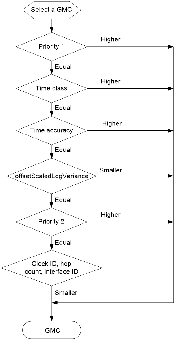
1. The clock nodes exchange Announce messages and compare the first priority, time class, time accuracy, and the second priority of the clocks carried in the Announce messages in sequence as shown in Figure 4 to select the grandmaster clock.
2. The master node periodically sends Announce messages to the member nodes. If the member nodes do not receive any Announce messages from the master node within the specified time period, they determine that the master node is invalid, and start to elect another grandmaster clock.
Figure 4 BMC comparison rule for GMC selection
Establishing master-member/subordinate relationships
The master-member/subordinate relationships between the clock nodes (except the TCs) on a PTP network are automatically determined based on the Best Master Clock (BMC) algorithm. You can also manually specify a role for the clock nodes.
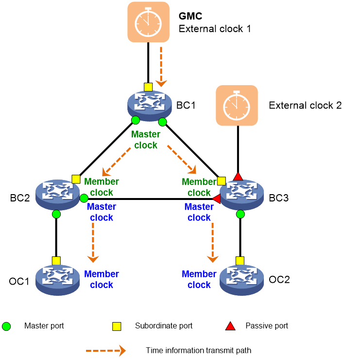
The following master-member/subordinate relationships exist:
· Master/Member node—A master node propagates time synchronization information, and a member node receives time synchronization information.
· Master/Member clock—The clock on a master node is a master clock. The clock on a member node is a member clock.
· Master/Subordinate port—A master port propagates time synchronization, and a subordinate port receives time synchronization information. The master and subordinate ports can be on a BC or an OC. A port that neither propagates nor receives timing information is a passive port. Passive ports are used to prevent PTP messages from forming loops.
After the grandmaster clock is elected and master-member/subordinate relationships are established, a loop-free, all connected shortest path tree with the grandmaster clock as the root is established in the PTP domain, as shown in Figure 5. Time is synchronized between the clock nodes in the domain along the path tree.
Figure 5 PTP master-member/subordinate relationships
Frequency synchronization
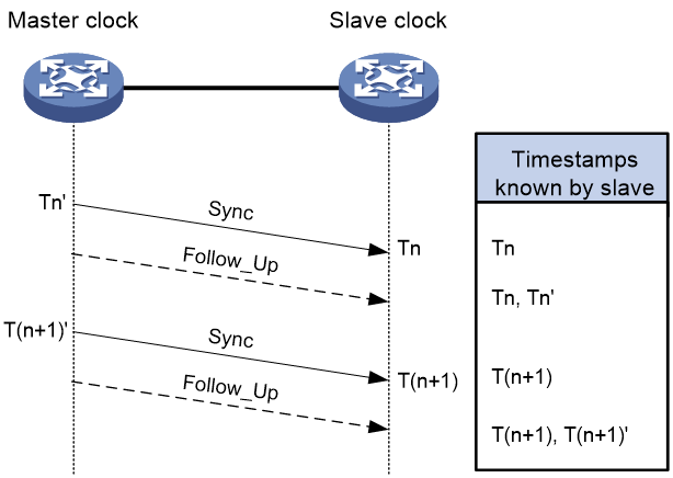
After the grandmaster clock is selected and master-member relationships are established, the master clock sends Sync messages to the member clocks periodically. Assume that the path delay between the master and member clock nodes remains unchanged, if the frequency of the slave clock and the master clock are synchronized, the time offset between the master and member clock will be the same at the same intervals, that is T(n+1)–Tn = T(n+1)'–Tn', as shown in Figure 6.
1. If T(n+1)–Tn > T(n+1)'–Tn', the member clock is faster in frequency than the master clock and will slow down its frequency.
2. If T(n+1)–Tn < T(n+1)'–Tn', the member clock is slower in frequency than the master clock and will adjust its frequency faster.
The member clock uses the formula T(n+1)–Tn / T(n+1)'–Tn' to calculate its frequency ratio with the master clock and adjust its clock frequency accordingly.
PTP frequency synchronization can run in single-step mode or two-step mode. The figure below shows the most commonly used two-step frequency synchronization mode. In single-step mode, Tn' and T(n+1)' timestamps are carried in a Sync message, and no Follow_Up message is sent.
Figure 6 PTP frequency synchronization in two-step mode
|
|
NOTE: For more information about one-step or two-step mode, see "Message types." |
Phase synchronization
About phase synchronization
After the grandmaster clock is selected and master-member relationships are established, the master and slave clocks exchange PTP messages periodically and begin also phase synchronization. The member clock calculates its time offset from the master clock based on the timestamps and adjusts its local time accordingly to achieve time synchronization with the master clock. (Accurate local time of a member clock = Current local time of the member clock – time offset)
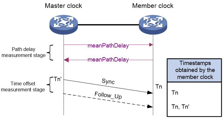
As shown in Figure 7, the time offset can be roughly calculated as Tn–Tn'. However, Tn–Tn' contains the transmission delay of the message on the path. To improve time synchronization accuracy, the time offset is measured and calculated through the following two stages:
1. Path delay measurement stage—The master and member clocks exchange synchronization messages and record the sending and receiving time of the messages. Based on the timestamps, each member clock calculates the total round-trip delay between them and the master clock. If the delays in the two directions are the same (also called network symmetry), half of the total round-trip delay is the one-way link delay (meanPathDelay). If the network delay is asymmetric and the difference between the delays in the sending direction and the receiving direction is known by other means, you can configure asymmetric delay to correct the path delay, to achieve precise time synchronization.
2. Time offset measurement stage—The master clock sends a Sync message to the member clock periodically and records its sending time Tn'. Upon receiving the Sync message, the member clock immediately records its receiving time and gets its time offset from the master clock as (Tn-Tn') – one-way path delay.
Figure 7 Phase synchronization
PTP defines two path delay measurement mechanisms: Request_Response and Peer Delay, both of which are based on network symmetry. All clock nodes in a PTP domain must use the same delay measurement mechanism. For a PTP network where the clock node types are all BC and OC, the request-response and peer delay measurement mechanisms do not have differences. In a PTP domain where a TC node is located, you must first determine whether to configure E2ETC or P2PTC clock nodes based on the networking conditions. If E2ETC clock nodes are configured, you must specify the request-response mechanism. If P2PTC clock nodes are configured, you must specify the peer delay mechanism.
Request_Response
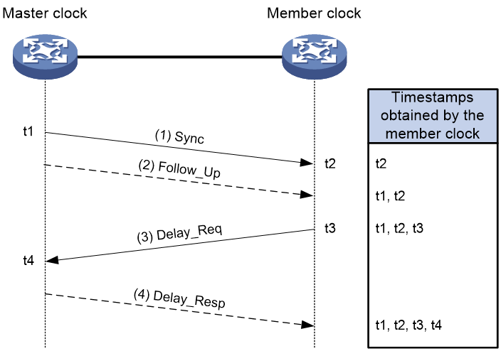
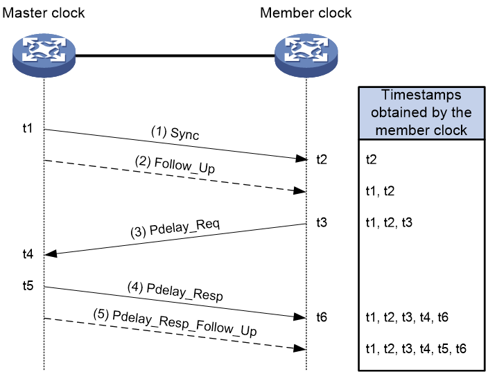
The Request_Response mechanism measures the average path delay between the master and member clock nodes by using the PTP messages as shown in Figure 8. A TC between master and member clock nodes does not calculate the average path delay. It only forwards PTP messages and carries the Sync message residence time on it to the downstream clock node.
Figure 8 shows the Request_Response mechanism in two-step mode.
1. The master clock sends a Sync message to the member clock, and records the sending time t1. Upon receiving the message, the member clock records the receiving time t2.
2. After sending the Sync message, the master clock sends a Follow_Up message that carries time t1 immediately.
3. The member clock sends a Delay_Req message to the master clock, and records the sending time t3. Upon receiving the message, the master clock records the receiving time t4.
4. The master clock returns a Delay_Resp message that carries time t4.
After this procedure, the member clock obtains all the four timestamps and can make the following calculations:
· Round-trip delay between the master and member clocks: (t2 – t1) + (t4 – t3)
· One-way delay between the master and member clocks: [(t2 – t1) + (t4 – t3)] / 2
· Offset between the member and master clocks: (t2 – t1) – [(t2 – t1) + (t4 – t3)] / 2 or [(t2 – t1) – (t4 – t3)] / 2
Figure 8 Request_Response mechanism (two-step node)
|
|
NOTE: For more information about one-step or two-step mode, see "Message types." |
Peer Delay
The Peer Delay mechanism measures the average path delay between two clock nodes. The two clock nodes (BC, TC, or OC) implementing this mechanism send Pdelay messages to each other, and calculate the one-way link delay between them independently. The message interaction process and delay calculation method are identical on the two nodes. TCs that exist between master and member clock nodes divide the synchronization path into multiple links and participate in delay calculation. The link delays and Sync message residence time on the TCs are carried to downstream nodes.
This mechanism can be implemented in one step or two-step mode: Figure 9 uses Clock node B as an example to describe the Peer Delay mechanism in two-step mode.
1. Clock node B sends a Pdelay_Req message to Clock node A, and records the sending time t1. Upon receiving the message, Clock node A records the receiving time t2.
2. Clock node A sends a Pdelay_Req message that carries t2 to Clock node B, and records the sending time t3. Upon receiving the message, Clock node B records the receiving time t4.
3. Clock node A sends a Pdelay_Resp_Follow_Up message carrying t3 to Clock node B immediately after sending the Pdelay_Req message.
After this procedure, Clock node B obtains all the four timestamps and can make the following calculations:
· Round-trip delay between Clock node A and Clock node B: (t2 – t1) + (t4 – t3)
· One-way delay between Clock node A and Clock node B: [(t2 – t1) + (t4 – t3)] / 2 = [(t3 – t2) + (t4 – t1)] / 2
· Time offset between the member clock and the master clock: Sync message receiving time on the member clock – Sync message sending time on the master clock – Total one-way delays on all links – Total Sync message residence time on all TCs.
Figure 9 Peer Delay mechanism (two-step mode)
|
|
NOTE: For more information about one-step or two-step mode, see "Message types." |
Application scenarios
1588v2 frequency and phase synchronization
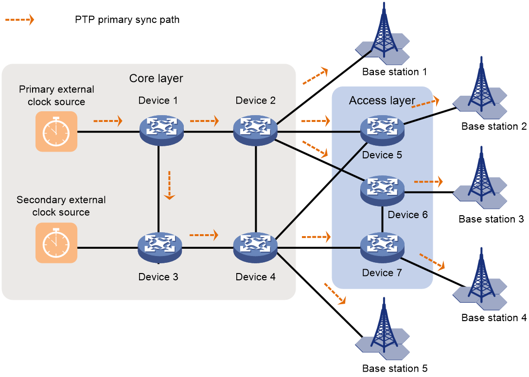
As shown in Figure 10, the base stations access the service provider's network through IP devices. For wireless clients to move smoothly between base stations, all neighboring base stations must be time synchronized with microsecond accuracy.
1. To enhance availability and reduce cost, deploy two clock sources in redundancy at the core layer of the service provider's network.
2. Configure 1588v2 on the network so that the clock source synchronizes the time on all network devices and base stations on the network. Use the primary clock source as the GMC. Enable the secondary clock source to take over the services automatically when the primary clock source fails. 1588v2 provides time synchronization among devices with sub-microsecond accuracy and can meet the requirements of wireless access devices for time synchronization precision.
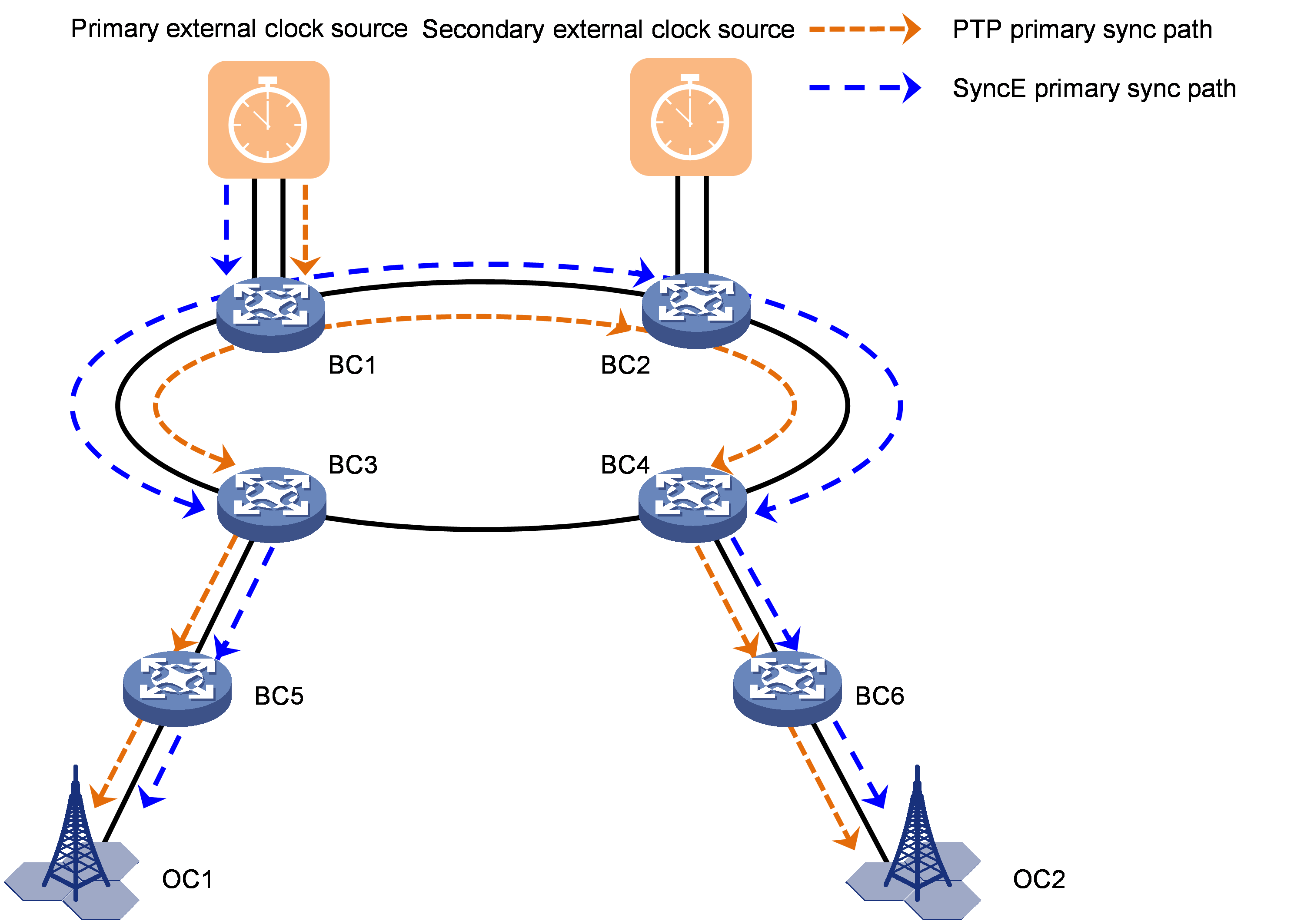
SyncE frequency synchronization + 1588v2 phase synchronization
As shown on the 5G access network in Figure 11, the base stations access the service provider's network through IP devices. For wireless clients to move smoothly between base stations, the neighboring base stations must be time synchronized with microsecond accuracy.
Deploy the SyncE frequency synchronization + 1588v2 phase synchronization solution for this scenario. This solution delivers the following advantages:
· Higher accuracy: SyncE can synchronize frequency with nanosecond accuracy, better than 1588v2.
· Great availability:
¡ Both SyncE and 1588v2 can provide frequency synchronization. The device preferentially uses SyncE for frequency synchronization. If the SyncE clock source fails or the link fails, resulting in frequency synchronization signal loss, the device will use 1588v2 for frequency synchronization.
¡ SyncE and PTP can share clock sources or use independent clock sources. When PTP fails and PTP time signals are lost, SyncE can continue to maintain frequency synchronization between the devices and keep the time offset between the devices within an acceptable range.
References
· AES67-2015, AES Standard for Audio Applications of Networks-High-Performance Streaming Audio-Over-IP Interoperability, 2015
· IEEE P802.1AS, Timing and Synchronization for Time-Sensitive Applications in Bridged Local Area Networks
· IEEE Std 1588-2008, IEEE Standard for a Precision Clock Synchronization Protocol for Networked Measurement and Control Systems, 2008
· ITU-T G.8275.1, Precision time protocol telecom profile for phase/time synchronization with full timing support from the network
· ITU-T G.8275.2, Precision time protocol telecom profile for phase/time synchronization with partial timing support from the network
· SMPTE ST 2059-2, SMPTE Profile for Use of IEEE-1588 Precision Time Protocol in Professional Broadcast Applications
