- Table of Contents
- Related Documents
-
| Title | Size | Download |
|---|---|---|
| 01-QoS configuration | 431.30 KB |
QoS processing flow in a device
Restrictions and guidelines for applying a QoS policy
Applying the QoS policy to an interface
Applying the QoS policy to a user profile
Display and maintenance commands for QoS policies
Priority mapping configuration methods
Priority mapping tasks at a glance
Configuring an uncolored priority map
Configuring a port to trust packet priority for priority mapping
Changing the port priority of an interface
Display and maintenance commands for priority mapping
Traffic evaluation and token buckets
Traffic policing configuration approaches
Configuring traffic policing by using the MQC approach
Configuring traffic policing for a user profile
Configuring the rate limit for an interface
Display and maintenance commands for traffic limit
Configuring congestion management
Cause, negative results, and countermeasure of congestion
Restrictions and guidelines for CBQ configuration
Configure AF and the minimum guaranteed bandwidth
Configuring EF and the maximum bandwidth
Setting the maximum available interface bandwidth
Displaying and maintaining congestion management
Restrictions and guidelines: Traffic filtering configuration
Appendix B Default priority maps
Appendix C Introduction to packet precedence
Appendix B Introduction to packet precedence
QoS overview
In data communications, Quality of Service (QoS) provides differentiated service guarantees for diversified traffic in terms of bandwidth, delay, jitter, and drop rate, all of which can affect QoS.
QoS manages network resources and prioritizes traffic to balance system resources.
The following section describes typical QoS service models and widely used QoS techniques.
QoS service models
This section describes several typical QoS service models.
Best-effort service model
The best-effort model is a single-service model. The best-effort model is not as reliable as other models and does not guarantee delay-free delivery.
The best-effort service model is the default model for the Internet and applies to most network applications. It uses the First In First Out (FIFO) queuing mechanism.
IntServ model
The integrated service (IntServ) model is a multiple-service model that can accommodate diverse QoS requirements. This service model provides the most granularly differentiated QoS by identifying and guaranteeing definite QoS for each data flow.
In the IntServ model, an application must request service from the network before it sends data. IntServ signals the service request with the RSVP. All nodes receiving the request reserve resources as requested and maintain state information for the application flow.
The IntServ model demands high storage and processing capabilities because it requires all nodes along the transmission path to maintain resource state information for each flow. This model is suitable for small-sized or edge networks. However, it is not suitable for large-sized networks, for example, the core layer of the Internet, where billions of flows are present.
DiffServ model
The differentiated service (DiffServ) model is a multiple-service model that can meet diverse QoS requirements. It is easy to implement and extend. DiffServ does not signal the network to reserve resources before sending data, as IntServ does.
QoS techniques in a network
The QoS techniques include the following features:
· Traffic classification.
· Traffic policing.
· Rate limiting.
· Congestion management.
The following section briefly introduces these QoS techniques.
All QoS techniques in this document are based on the DiffServ model.
Figure 1 Position of the QoS techniques in a network
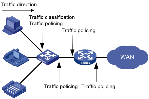
As shown in Figure 1, traffic classification and traffic policing mainly implement the following functions:
· Traffic classification—Uses match criteria to assign packets with the same characteristics to a traffic class. Based on traffic classes, you can provide differentiated services.
· Traffic policing—Polices flows and imposes penalties to prevent aggressive use of network resources. You can apply traffic policing to both incoming and outgoing traffic of a port.
· Congestion management—Provides a resource scheduling policy to determine the packet forwarding sequence when congestion occurs. Congestion management usually applies to the outgoing traffic of a port.
QoS processing flow in a device
Figure 2 briefly describes how the QoS module processes traffic.
1. Traffic classifier identifies and classifies traffic for subsequent QoS actions.
2. The QoS module takes various QoS actions on classified traffic as configured, depending on the traffic processing phase and network status. For example, you can configure traffic policing for incoming traffic.
QoS configuration approaches
You can configure QoS by using the MQC approach or non-MQC approach.
In the modular QoS configuration (MQC) approach, you configure QoS service parameters by using QoS policies. A QoS policy defines QoS actions to take on different classes of traffic and can be applied to an object (such as an interface) to control traffic.
In the non-MQC approach, you configure QoS service parameters without using a QoS policy. For example, you can use the rate limit feature to set a rate limit on an interface without using a QoS policy.
Some features support both approaches, but some support only one.
Configuring a QoS policy
About QoS policies
A QoS policy has the following components:
· Traffic class—Defines criteria to match packets.
· Traffic behavior—Defines QoS actions to take on matching packets.
By associating a traffic class with a traffic behavior, a QoS policy can perform the QoS actions on matching packets.
A QoS policy can have multiple class-behavior associations.
QoS policy tasks at a glance
To configure a QoS policy, perform the following tasks:
2. Defining a traffic behavior
¡ Applying the QoS policy to an interface
¡ Applying the QoS policy to a user profile
Defining a traffic class
1. Enter system view.
system-view
2. Create a traffic class and enter traffic class view.
traffic classifier classifier-name [ operator { and | or } ]
3. Configure a match criterion.
if-match [ not ] match-criteria
By default, no match criterion is configured.
For more information, see the if-match command in ACL and QoS Command Reference.
Defining a traffic behavior
1. Enter system view.
system-view
2. Create a traffic behavior and enter traffic behavior view.
traffic behavior behavior-name
3. Configure an action in the traffic behavior.
By default, no action is configured for a traffic behavior.
You can configure multiple actions in a traffic behavior.
For more information about configuring an action, see the subsequent chapters for traffic policing, traffic filtering, priority marking, and so on.
Defining a QoS policy
Restrictions and guidelines
A QoS policy can contain multiple class-behavior associations. The device matches a packet against the class-behavior associations in their configuration order. When a match is found, the device stops the match process and takes the actions in the matching class-behavior association. Some actions might be exclusive with each other in the same behavior.
Procedure
1. Enter system view.
system-view
2. Create a QoS policy and enter QoS policy view.
qos policy policy-name
3. Associate a traffic class with a traffic behavior to create a class-behavior association in the QoS policy.
classifier classifier-name behavior behavior-name [ insert-before before-classifier-name ]
By default, a traffic class is not associated with a traffic behavior.
Repeat this step to create more class-behavior associations.
Applying the QoS policy
Application destinations
You can apply a QoS policy to the following destinations:
· Interface—The QoS policy can be applied to the traffic sent or received on an interface.
· User profile—The QoS policy can be applied to the traffic sent or received by the online users of the user profile.
Restrictions and guidelines for applying a QoS policy
You can modify traffic classes, traffic behaviors, and class-behavior associations in a QoS policy even after it is applied (except that it is applied to a user profile). If a traffic class uses an ACL for traffic classification, you can delete or modify the ACL.
If an action in a traffic behavior cannot take effect, all other actions in the traffic behavior do not take effect.
Applying the QoS policy to an interface
Restrictions and guidelines
A QoS policy can be applied to multiple interfaces. However, only one QoS policy can be applied to one direction (inbound or outbound) of an interface.
The QoS policy applied to the outgoing traffic on an interface does not regulate local packets. Local packets refer to critical protocol packets sent by the local system for operation maintenance. The most common local packets include link maintenance, RIP, LDP, and SSH packets.
Procedure
1. Enter system view.
system-view
2. Enter interface view.
interface interface-type interface-number
3. Apply the QoS policy to the interface.
qos apply policy policy-name { inbound | outbound }
By default, no QoS policy is applied to an interface.
Applying the QoS policy to a user profile
About this task
When a user profile is configured, you can perform traffic policing based on users. After a user passes authentication, the authentication server sends the name of the user profile associated with the user to the device. The QoS policy configured in user profile view takes effect only when users come online.
Restrictions and guidelines
You can apply a QoS policy to multiple user profiles. In one direction of each user profile, only one policy can be applied. To modify a QoS policy already applied to a direction, first remove the applied QoS policy.
Procedure
1. Enter system view.
system-view
2. Enter user profile view.
user-profile profile-name
3. Apply the QoS policy to the user profile.
qos apply policy policy-name { inbound | outbound }
By default, no QoS policy is applied to a user profile.
|
Parameter |
Description |
|
inbound |
Applies a QoS policy to the incoming traffic (traffic received by the device from online users). |
|
outbound |
Applies a QoS policy to the outgoing traffic (traffic sent by the device to online users). |
Display and maintenance commands for QoS policies
Execute display commands in any view and reset commands in user view.
|
Task |
Command |
|
Display QoS policy configuration. |
display qos policy { system-defined | user-defined } [ policy-name [ classifier classifier-name ] ] |
|
Display QoS policies applied to SDWAN tunnels on a tunnel interface. |
display qos policy sdwan tunnel number [ site-id site-id device-id device-id interface-id interface-id ] outbound |
|
Display information about QoS policies applied to interfaces. |
display qos policy interface [ interface-type interface-number ] [ inbound | outbound ] |
|
Display information about QoS policies applied to user profiles. |
display qos policy user-profile [ name profile-name ] [ inbound | outbound ] |
|
Display traffic behavior configuration. |
display traffic behavior { system-defined | user-defined } [ behavior-name ] |
|
Display traffic class configuration. |
display traffic classifier { system-defined | user-defined } [ classifier-name ] |
|
Clear the statistics for QoS policies applied to SDWAN tunnels on a tunnel interface. |
reset qos policy sdwan tunnel number [ site-id site-id device-id device-id interface-id interface-id ] outbound |
Configuring priority mapping
About priority mapping
When a packet arrives, a device assigns a set of QoS priority parameters to the packet based on either of the following:
· A priority field carried in the packet.
· The port priority of the incoming port.
This process is called priority mapping. During this process, the device can modify the priority of the packet according to the priority mapping rules. The set of QoS priority parameters decides the scheduling priority and forwarding priority of the packet.
Priority mapping is implemented with priority maps and involves the following priorities:
· 802.11e priority.
· 802.1p priority.
· DSCP.
· EXP.
· IP precedence.
· Local precedence.
· Drop priority.
About priorities
Priorities include the following types: priorities carried in packets, and priorities locally assigned for scheduling only.
Packet-carried priorities include 802.1p priority, DSCP precedence, IP precedence, and EXP. These priorities have global significance and affect the forwarding priority of packets across the network. For more information about these priorities, see "Appendix C Introduction to packet precedence."
Locally assigned priorities only have local significance. They are assigned by the device only for scheduling. These priorities include the local precedence, drop priority, and user priority, as follows:
· Local precedence—Used for queuing. A local precedence value corresponds to an output queue. A packet with higher local precedence is assigned to a higher priority output queue to be preferentially scheduled.
· Drop priority—Used for making packet drop decisions. Packets with the highest drop priority are dropped preferentially.
· User priority—Precedence that the device automatically extracts from a priority field of the packet according to its forwarding path. It is a parameter for determining the scheduling priority and forwarding priority of the packet. The user priority represents the following items:
¡ The 802.1p priority for Layer 2 packets.
¡ The IP precedence for Layer 3 packets.
¡ The EXP for MPLS packets.
Priority maps
The device provides various types of priority maps. By looking through a priority map, the device decides which priority value to assign to a packet for subsequent packet processing.
The default priority maps (as shown in Appendix B Default priority maps) are available for priority mapping. They are adequate in most cases. If a default priority map cannot meet your requirements, you can modify the priority map as required.
Priority mapping configuration methods
You can configure priority mapping by using any of the following methods:
· Configuring priority trust mode—In this method, you can configure a port to look up a trusted priority type (802.1p, for example) in incoming packets in the priority maps. Then, the system maps the trusted priority to the target priority types and values.
· Changing port priority—If no packet priority is trusted, the port priority of the incoming port is used. By changing the port priority of a port, you change the priority of the incoming packets on the port.
Priority mapping process
On receiving an Ethernet packet on a port, the switch marks the scheduling priorities (local precedence and drop precedence) for the Ethernet packet. This procedure is done according to the priority trust mode of the receiving port and the 802.1Q tagging status of the packet, as shown in Figure 3.
Figure 3 Priority mapping process for an Ethernet packet
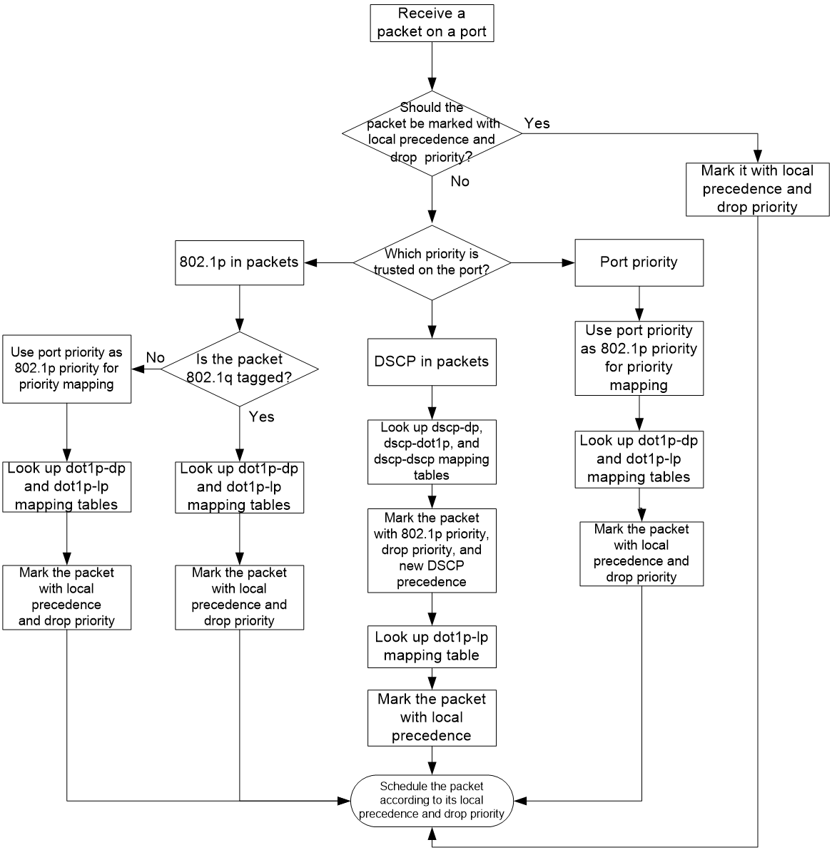
For information about priority marking, see "Configuring priority marking."
Priority mapping tasks at a glance
To configure priority mapping, perform the following tasks:
1. (Optional.) Configuring a priority map
2. Configuring a priority mapping method:
¡ Configuring a port to trust packet priority for priority mapping
¡ Changing the port priority of an interface
Configuring a priority map
Configuring an uncolored priority map
1. Enter system view.
system-view
2. Enter priority map view.
qos map-table { dot11e-lp | dot1p-lp | dscp-lp | lp-dot11e | lp-dot1p | lp-dscp }
3. Configure mappings for the priority map.
import import-value-list export export-value
By default, the default priority maps are used. For more information, see "Appendix B Default priority maps."
If you execute this command multiple times, the most recent configuration takes effect.
Configuring a port to trust packet priority for priority mapping
About this task
You can configure the device to trust a particular priority field carried in packets for priority mapping on ports or globally. When you configure the trusted packet priority type on an interface, use the following available keywords:
· dot1p—Uses the 802.1p priority of received packets for mapping.
· dscp—Uses the DSCP precedence of received IP packets for mapping.
You can create a configuration profile on the AC and configure the priority trust mode to be deployed to APs in configuration profile view, and then associate one or more APs with the configuration profile. When APs come online through the AC, the AC can deploy the priority trust mode in the configuration profile to all APs associated with that configuration profile. For more information about configuration profiles, see configuration file management in Fundamentals Configuration Guide.
Procedure
1. Enter system view.
system-view
2. Enter interface view or configuration profile-interface view.
¡ Enter interface view.
interface interface-type interface-number
¡ Enter configuration profile-interface view.
configuration profile profile-name
interface interface-type interface-number
3. Configure the trusted packet priority type.
qos trust { dot1p | dscp }
By default, an interface does not trust any packet priority and uses the port priority as the 802.1p priority for mapping.
4. Return to system view.
quit
Changing the port priority of an interface
About this task
If an interface does not trust any packet priority, the device uses its port priority to look for priority parameters for the incoming packets. By changing port priority, you can prioritize traffic received on different interfaces.
You can create a configuration profile on the AC and configure the port priority to be deployed to APs in configuration profile view, and then associate one or more APs with the configuration profile. When APs come online through the AC, the AC can deploy the priority trust mode in the configuration profile to all APs associated with that configuration profile. For more information about configuration profiles, see configuration file management in Fundamentals Configuration Guide.
Procedure
1. Enter system view.
system-view
2. Enter interface view or configuration profile-interface view.
¡ Enter interface view.
interface interface-type interface-number
¡ Enter configuration profile-interface view.
configuration profile profile-name
interface interface-type interface-number
3. Set the port priority of the interface.
qos priority priority-value
The default setting is 0.
Display and maintenance commands for priority mapping
Execute display commands in any view.
|
Task |
Command |
|
Display priority map configuration. |
display qos map-table [ dot11e-lp | dot1p-lp | dscp-lp | lp-dot11e | lp-dot1p | lp-dscp ] |
|
Display the trusted packet priority type on a port. |
display qos trust interface [ interface-type interface-number ] |
Configuring traffic limit
About traffic limit
Traffic limit helps assign network resources (including bandwidth) and increase network performance. For example, you can configure a flow to use only the resources committed to it in a certain time range. This avoids network congestion caused by burst traffic.
Traffic policing controls the traffic rate and resource usage according to traffic specifications. You can use token buckets for evaluating traffic specifications.
Traffic evaluation and token buckets
Token bucket features
A token bucket is analogous to a container that holds a certain number of tokens. Each token represents a certain forwarding capacity. The system puts tokens into the bucket at a constant rate. When the token bucket is full, the extra tokens cause the token bucket to overflow.
Evaluating traffic with the token bucket
A token bucket mechanism evaluates traffic by looking at the number of tokens in the bucket. If the number of tokens in the bucket is enough for forwarding the packets:
· The traffic conforms to the specification (called conforming traffic).
· The corresponding tokens are taken away from the bucket.
Otherwise, the traffic does not conform to the specification (called excess traffic).
A token bucket has the following configurable parameters:
· Mean rate at which tokens are put into the bucket, which is the permitted average rate of traffic. It is usually set to the committed information rate (CIR).
· Burst size or the capacity of the token bucket. It is the maximum traffic size permitted in each burst. It is usually set to the committed burst size (CBS). The set burst size must be greater than the maximum packet size.
Each arriving packet is evaluated.
Complicated evaluation
You can set two token buckets, bucket C and bucket E, to evaluate traffic in a more complicated environment and achieve more policing flexibility. The following are main mechanisms used for complicated evaluation:
· Single rate two color—Uses one token bucket and the following parameters:
¡ CIR—Rate at which tokens are put into bucket C. It sets the average packet transmission or forwarding rate allowed by bucket C.
¡ CBS—Size of bucket C, which specifies the transient burst of traffic that bucket C can forward.
When a packet arrives, the following rules apply:
¡ If bucket C has enough tokens to forward the packet, the packet is colored green.
¡ Otherwise, the packet is colored red.
· Single rate three color—Uses two token buckets and the following parameters:
¡ CIR—Rate at which tokens are put into bucket C. It sets the average packet transmission or forwarding rate allowed by bucket C.
¡ CBS—Size of bucket C, which specifies the transient burst of traffic that bucket C can forward.
¡ EBS—Size of bucket E minus size of bucket C, which specifies the transient burst of traffic that bucket E can forward. The EBS cannot be 0. The size of E bucket is the sum of the CBS and EBS.
When a packet arrives, the following rules apply:
¡ If bucket C has enough tokens, the packet is colored green.
¡ If bucket C does not have enough tokens but bucket E has enough tokens, the packet is colored yellow.
¡ If neither bucket C nor bucket E has sufficient tokens, the packet is colored red.
· Two rate three color—Uses two token buckets and the following parameters:
¡ CIR—Rate at which tokens are put into bucket C. It sets the average packet transmission or forwarding rate allowed by bucket C.
¡ CBS—Size of bucket C, which specifies the transient burst of traffic that bucket C can forward.
¡ PIR—Rate at which tokens are put into bucket E, which specifies the average packet transmission or forwarding rate allowed by bucket E.
¡ EBS—Size of bucket E, which specifies the transient burst of traffic that bucket E can forward.
When a packet arrives, the following rules apply:
¡ If bucket C has enough tokens, the packet is colored green.
¡ If bucket C does not have enough tokens but bucket E has enough tokens, the packet is colored yellow.
¡ If neither bucket C nor bucket E has sufficient tokens, the packet is colored red.
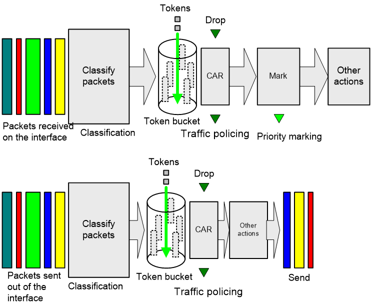
Traffic policing
A typical application of traffic policing is to supervise the specification of traffic entering a network and limit it within a reasonable range. Another application is to "discipline" the extra traffic to prevent aggressive use of network resources by an application. For example, you can limit bandwidth for HTTP packets to less than 50% of the total. If the traffic of a session exceeds the limit, traffic policing can drop the packets or set the precedence of the packets. Figure 4 shows an example of policing outbound traffic on an interface.
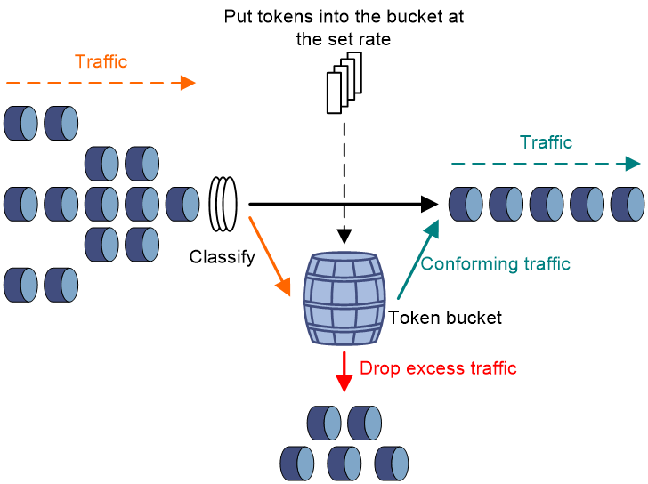
· Forwarding the packet.
· Dropping the packet.
· Forwarding the packet with its precedence re-marked.
· Delivering the packet to next-level traffic policing with its precedence re-marked.
Rate limit
The rate limit of an interface specifies the maximum rate for forwarding packets (excluding critical packets).
Rate limit also uses token buckets for traffic control. When rate limit is configured on an interface, a token bucket handles all packets to be sent through the interface for rate limiting. If enough tokens are in the token bucket, packets can be forwarded. Otherwise, packets are put into QoS queues for congestion management. In this way, the traffic passing the interface is controlled.
Figure 5 Rate limit implementation
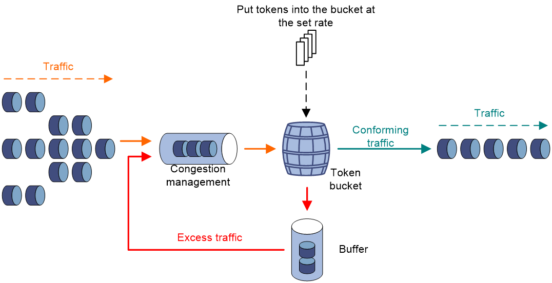
The token bucket mechanism limits traffic rate when accommodating bursts. It allows bursty traffic to be transmitted if enough tokens are available. If tokens are scarce, packets cannot be transmitted until efficient tokens are generated in the token bucket. It restricts the traffic rate to the rate for generating tokens.
Rate limit controls the total rate of all packets on an interface. It is easier to use than traffic policing in controlling the total traffic rate.
Configuring traffic policing
Traffic policing configuration approaches
You can configure traffic policing by using the MQC approach or the non-MQC approach. If both approaches are used, the MQC configuration takes effect.
You can configure traffic policing for a user profile by using the non-MQC approach.
If traffic policing is configured by using both the MQC approach and non-MQC approach, the configuration in MQC approach takes effect.
Configuring traffic policing by using the MQC approach
Restrictions and guidelines
The device supports applying traffic policing to an interface or user profile.
Procedure
1. Enter system view.
system-view
2. Define a traffic class.
a. Create a traffic class and enter traffic class view.
traffic classifier classifier-name [ operator { and | or } ]
b. Configure a match criterion.
if-match [ not ] match-criteria
By default, no match criterion is configured.
For more information about the if-match command, see ACL and QoS Command Reference.
c. Return to system view.
quit
3. Define a traffic behavior.
a. Create a traffic behavior and enter traffic behavior view.
traffic behavior behavior-name
b. Configure a traffic policing action.
car cir committed-information-rate [ cbs committed-burst-size ] [ green action | red action ] *
By default, no traffic policing action is configured.
c. Return to system view.
quit
4. Define a QoS policy.
a. Create a QoS policy and enter QoS policy view.
qos policy policy-name
b. Associate the traffic class with the traffic behavior in the QoS policy.
classifier classifier-name behavior behavior-name
By default, a traffic class is not associated with a traffic behavior.
c. Return to system view.
quit
5. Apply the QoS policy.
For more information, see "Applying the QoS policy."
By default, no QoS policy is applied.
Configuring traffic policing for a user profile
About this task
When a user profile is configured, you can perform traffic policing based on users. After a user passes authentication, the authentication server sends the name of the user profile associated with the user to the device. When any user of the user profile logs in, the authentication server automatically applies the CAR parameters configured for the user profile to the user. When the user logs off, the system automatically removes the CAR configuration without manual intervention.
Procedure
1. Enter system view.
system-view
2. Enter user profile view.
user-profile profile-name
3. Configure a CAR policy for the user profile.
qos car { inbound | outbound } any cir committed-information-rate [ cbs committed-burst-size ]
By default, no CAR policy is configured for a user profile.
Configuring the rate limit
Configuring the rate limit for an interface
1. Enter system view.
system-view
2. Enter interface view.
interface interface-type interface-number
3. Configure the rate limit for the interface.
qos lr outbound cir committed-information-rate [ cbs committed-burst-size [ ebs excess-burst-size ] ]
By default, no rate limit is configured on an interface.
Display and maintenance commands for traffic limit
Execute display commands in any view.
|
Task |
Command |
|
Display rate limit configuration and statistics. |
display qos lrinterface [ interface-type interface-number ] |
|
Display traffic behavior configuration. |
display traffic behavior user-defined [ behavior-name ] |
Configuring congestion management
About congestion management
Cause, negative results, and countermeasure of congestion
Congestion occurs on a link or node when traffic size exceeds the processing capability of the link or node. It is typical of a statistical multiplexing network and can be caused by link failures, insufficient resources, and various other causes. Figure 6 shows common congestion scenarios.
Figure 6 Traffic congestion causes

Congestion can introduce the following negative results:
· Increased delay and jitter during packet transmission.
· Decreased network throughput and resource use efficiency.
· Network resource (memory, in particular) exhaustion and system breakdown.
Congestion is unavoidable in switched networks or multiuser application environments. To improve the service performance of your network, implement congestion management policies.
For example, congestion management defines a resource dispatching policy to prioritize packets for forwarding when congestion occurs.
Congestion management methods
Congestion management involves queue creating, traffic classification, packet enqueuing, and queue scheduling.
Queuing is a common congestion management technique. It classifies traffic into queues and picks out packets from each queue by using an algorithm. Various queuing algorithms are available, and each addresses a particular network traffic problem. Your choice of algorithm significantly affects bandwidth assignment, delay, and jitter.
The device supports only the CBQ queuing.
CBQ
Figure 7 CBQ
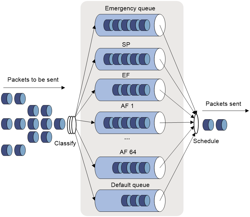
Class-based queuing (CBQ) extends WFQ by supporting user-defined classes. When network congestion occurs, CBQ uses user-defined traffic match criteria to enqueue packets. Before packets are enqueued, congestion avoidance actions, such as tail drop or WRED and bandwidth restriction check, are performed. When being dequeued, packets are scheduled by WFQ.
CBQ provides the following queues:
· Emergency queue—Enqueues emergent packets. The emergency queue is a FIFO queue without bandwidth restriction.
· Strict priority (SP) queuing—SP queuing is designed for mission-critical applications. Mission-critical applications require preferential treatment to reduce the response delay when congestion occurs. With SP queuing, CBQ can provide strict priority service. A maximum of 64 SP queues are supported.
· Low Latency Queuing (LLQ)—An EF queue. Because packets are fairly treated in CBQ, delay-sensitive flows like video and voice packets might not be transmitted timely. To solve this problem, LLQ combines PQ and CBQ to preferentially transmit delay-sensitive flows like voice packets. When defining traffic classes for LLQ, you can configure a class of packets to be preferentially transmitted. The packets of all priority classes are assigned to the same priority queue. Bandwidth restriction on each class of packets is checked before the packets are enqueued. During the dequeuing operation, packets in the priority queue are transmitted first. To reduce the delay of the other queues except the priority queue, LLQ assigns the maximum available bandwidth to each priority class. The bandwidth value polices traffic during congestion. When no congestion is present, a priority class can use more than the bandwidth assigned to it. During congestion, the packets of each priority class exceeding the assigned bandwidth are discarded.
· Bandwidth queuing (BQ)—An AF queue. The BQ provides guaranteed bandwidth for AF traffic, and schedules the AF classes proportionally. The system supports up to 64 AF queues.
· Default queue—A WFQ queue. The default queue transmits the BE traffic by using the remaining interface bandwidth.
The system matches packets with classification rules in the following order:
· Match packets with priority classes and then the other classes.
· Match packets with priority classes in the configuration order.
· Match packets with other classes in the configuration order.
· Match packets with classification rules in a class in the configuration order.
Configuring CBQ
About CBQ
The system predefines the following classes, traffic behaviors, and policies:
Predefined classes
The system predefines some classes and defines general rules for the classes. You can use the following predefined classes when defining a policy:
· default-class—Matches the default traffic.
· ef, af1, af2, af3, af4—Matches IP DSCP value ef, af1, af2, af3, af4, respectively.
· ip-prec0, ip-prec1, …ip-prec7—Matches IP precedence value 0, 1, …7, respectively.
· mpls-exp0, mpls-exp1, …mpls-exp7—Matches MPLS EXP value 0, 1, …7, respectively.
Predefined traffic behaviors
The system predefines some traffic behaviors and defines QoS features for the behaviors.
· ef—Assigns a class of packets to the EF queue and assigns 20% of the available interface or PVC bandwidth to the class of packets.
· af—Assigns a class of packets to the AF queue and assigns 20% of the available interface or PVC bandwidth to the class of packets.
· be—Defines no features.
· be-flow-based—Assigns a class of packets to a WFQ queue and specifies the drop policy as WRED. By default, 256 WFQ queues exist, and WRED is an IP precedence-based drop policy.
Predefined QoS policy
The system predefines a QoS policy, specifies a predefined class for the policy and associates a predefined behavior with the class. The policy is named default, with the default CBQ action.
The policy default is defined as follows:
· Associates the predefined class ef with the predefined traffic behavior ef.
· Associates predefined classes af1 through af4 with the predefined traffic behavior af.
· Associates the predefined class default-class with the predefined traffic behavior be.
Restrictions and guidelines for CBQ configuration
When you configure CBQ, follow these restrictions and guidelines:
· Only one of the following queuing actions can be configured in the same behavior:
¡ AF.
¡ EF.
¡ SP.
¡ WFQ.
· To configure queue af for multiple classes of a policy, you must configure them in one of the following units:
¡ Bandwidth in kbps.
¡ Percentage of the available bandwidth.
¡ Percentage of the remaining bandwidth.
· In a QoS policy, if AF is configured in percentage of the remaining bandwidth, EF can be configured in absolute value or in percentage.
· In a QoS policy, if AF is configured in absolute value or in percentage, EF can be configured in absolute value or in percentage.
· You must configure the rate limit on a subinterface for the CBQ feature to take effect on the subinterface.
· The default class cannot be associated with a traffic behavior including EF or SP.
· You can associate the traffic behavior that contains a WFQ action only with the default class.
· RTPQ and CBQ are mutually exclusive. CBQ can use LLQ to provide priority service for real-time traffic.
Configure AF and the minimum guaranteed bandwidth
Restrictions and guidelines
· The undo queue af command also cancels the queue-length command configuration.
· A QoS policy that contains an AF action can be applied to the outbound direction of an interface or the inbound direction for a user profile. To modify a QoS policy applied to a user profile, follow these steps:
a. Remove the QoS policy from the user profile.
b. Configure a new QoS policy.
c. Apply the new QoS policy to the user profile.
Procedure
1. Enter system view.
system-view
2. Define a traffic class.
a. Create a traffic class and enter traffic class view.
traffic classifier classifier-name [ operator { and | or } ]
b. Configure a match criterion.
if-match [ not ] match-criteria
By default, no match criterion is configured.
For more information about configuring match criteria, see ACL and QoS Command Reference.
c. Return to system view.
quit
3. Define a traffic behavior.
a. Create a traffic behavior and enter traffic behavior view.
traffic behavior behavior-name
b. Configure AF and the minimum guaranteed bandwidth.
queue af bandwidth { bandwidth | pct percentage | remaining-pct remaining-percentage }
By default, AF is not configured.
c. (Optional.) Set the maximum queue size.
queue-length queue-length
The default setting is 64 packets.
If the burst traffic is too heavy, increase the queue length to make queue scheduling more accurate.
d. Return to system view.
quit
4. Define a QoS policy.
a. Create a QoS policy and enter QoS policy view.
qos policy policy-name
b. Associate a traffic behavior with a class in the policy.
classifier classifier-name behavior behavior-name
By default, a class is not associated with a behavior.
c. Return to system view.
quit
5. Apply the QoS policy.
For more information, see "Applying the QoS policy."
By default, no QoS policy is applied.
Configuring EF and the maximum bandwidth
Restrictions and guidelines
A QoS policy that contains an EF action can be applied to the outbound direction of an interface or the inbound direction for a user profile. To modify a QoS policy applied to a user profile, follow these steps:
1. Remove the QoS policy from the user profile.
2. Configure a new QoS policy.
3. Apply the new QoS policy to the user profile.
Procedure
1. Enter system view.
system-view
2. Define a traffic class.
a. Create a traffic class and enter traffic class view.
traffic classifier classifier-name [ operator { and | or } ]
b. Configure a match criterion.
if-match [ not ] match-criteria
By default, no match criterion is configured.
For more information about configuring match criteria, see ACL and QoS Command Reference.
c. Return to system view.
quit
3. Define a traffic behavior.
a. Create a traffic behavior and enter traffic behavior view.
traffic behavior behavior-name
b. Configure EF and the maximum bandwidth.
queue ef bandwidth { bandwidth [ cbs burst ] | pct percentage [ cbs-ratio ratio] }
By default, EF is not configured.
c. Return to system view.
quit
4. Define a QoS policy.
a. Create a QoS policy and enter QoS policy view.
qos policy policy-name
b. Associate a traffic behavior with a class in the policy.
classifier classifier-name behavior behavior-name
By default, a class is not associated with a behavior.
c. Return to system view.
quit
5. Apply the QoS policy.
For more information, see "Applying the QoS policy."
By default, no QoS policy is applied.
Setting the maximum available interface bandwidth
Restrictions and guidelines
· The maximum available interface bandwidth refers to the maximum interface bandwidth used for bandwidth check when CBQ enqueues packets. It is not the actual bandwidth of the physical interface.
· As a best practice, set the maximum available interface bandwidth to be smaller than the actual available bandwidth of the physical interface or logical link.
· On subinterfaces, you must configure the bandwidth command to provide base bandwidth for CBQ calculation.
¡ If no maximum available bandwidth is set for an interface, the following bandwidth is used for CBQ calculation:
¡ The actual baud rate or rate if the interface is a physical one.
¡ 0 kbps if the interface is a virtual interface, for example, tunnel interface or Layer 3 aggregate interface.
Procedure
1. Enter system view.
system-view
2. Enter interface view.
interface interface-type interface-number
3. Set the maximum available bandwidth of the interface.
bandwidth bandwidth-value
For more information about this command, see Interface Command Reference.
Displaying and maintaining congestion management
Execute display commands in any view and reset commands in user view.
|
Task |
Command |
|
Display QoS policy configuration. |
display qos policy { system-defined | user-defined } [ policy-name [ classifier classifier-name ] ] |
|
Display information about QoS policies applied to interfaces. |
display qos policy interface [ interface-type interface-number ] [ inbound | outbound ] |
|
Display the CBQ configuration and statistics for interfaces. |
display qos queue cbq nterface [ interface-type interface-number ] |
|
Display queuing configuration and statistics for interfaces. |
display qos queue interface [ interface-type interface-number ] |
|
Display traffic behavior configuration. |
display traffic behavior { system-defined | user-defined } [ behavior-name ] |
|
Display class configuration. |
display traffic classifier { system-defined | user-defined } [ classifier-name ] |
Configuring traffic filtering
About traffic filtering
You can filter in or filter out traffic of a class by associating the class with a traffic filtering action. For example, you can filter packets sourced from an IP address according to network status.
Restrictions and guidelines: Traffic filtering configuration
The device supports the following application destinations for traffic filtering:
· Interface.
· User profile.
Procedure
1. Enter system view.
system-view
2. Define a traffic class.
a. Create a traffic class and enter traffic class view.
traffic classifier classifier-name [ operator { and | or } ]
b. Configure a match criterion.
if-match [ not ] match-criteria
By default, no match criterion is configured.
For more information about configuring match criteria, see ACL and QoS Command Reference.
c. Return to system view.
quit
3. Define a traffic behavior.
a. Create a traffic behavior and enter traffic behavior view.
traffic behavior behavior-name
b. Configure the traffic filtering action.
filter { deny | permit }
By default, no traffic filtering action is configured.
If a traffic behavior has the filter deny action, all other actions in the traffic behavior do not take effect.
c. Return to system view.
quit
4. Define a QoS policy.
a. Create a QoS policy and enter QoS policy view.
qos policy policy-name
b. Associate the traffic class with the traffic behavior in the QoS policy.
classifier classifier-name behavior behavior-name
By default, a traffic class is not associated with a traffic behavior.
c. Return to system view.
quit
5. Apply the QoS policy.
For more information, see "Applying the QoS policy."
By default, no QoS policy is applied.
6. (Optional.) Display the traffic filtering configuration.
display traffic behavior user-defined [ behavior-name ]
This command is available in any view.
Configuring priority marking
About priority marking
Priority marking sets the priority fields or flag bits of packets to modify the priority of packets. For example, you can use priority marking to set IP precedence or DSCP for a class of IP packets to control the forwarding of these packets.
To configure priority marking to set the priority fields or flag bits for a class of packets, perform the following tasks:
1. Configure a traffic behavior with a priority marking action.
2. Associate the traffic class with the traffic behavior.
Priority marking can be used together with priority mapping. For more information, see "Configuring priority mapping."
Configuring priority marking
Restrictions and guidelines
The device supports the following application destinations for priority marking:
· Interface.
· User profile.
Procedure
1. Enter system view.
system-view
2. Define a traffic class.
a. Create a traffic class and enter traffic class view.
traffic classifier classifier-name [ operator { and | or } ]
b. Configure a match criterion.
if-match [ not ] match-criteria
By default, no match criterion is configured.
For more information about the if-match command, see ACL and QoS Command Reference.
c. Return to system view.
quit
3. Define a traffic behavior.
a. Create a traffic behavior and enter traffic behavior view.
traffic behavior behavior-name
b. Configure a priority marking action.
For configurable priority marking actions, see the remark commands in ACL and QoS Command Reference.
c. Return to system view.
quit
4. Define a QoS policy.
a. Create a QoS policy and enter QoS policy view.
qos policy policy-name
b. Associate the traffic class with the traffic behavior in the QoS policy.
classifier classifier-name behavior behavior-name
By default, a traffic class is not associated with a traffic behavior.
c. Return to system view.
quit
5. Apply the QoS policy.
For more information, see "Applying the QoS policy."
By default, no QoS policy is applied.
6. (Optional.) Display the priority marking configuration.
display traffic behavior user-defined [ behavior-name ]
This command is available in any view.
Appendixes
Appendix A Acronyms
Table 1 Appendix A Acronyms
|
Acronym |
Full spelling |
|
AF |
Assured Forwarding |
|
BE |
Best Effort |
|
BQ |
Bandwidth Queuing |
|
CAR |
Committed Access Rate |
|
CBS |
Committed Burst Size |
|
CBQ |
Class Based Queuing |
|
CE |
Congestion Experienced |
|
CIR |
Committed Information Rate |
|
CQ |
Custom Queuing |
|
DiffServ |
Differentiated Service |
|
DSCP |
Differentiated Services Code Point |
|
EBS |
Excess Burst Size |
|
ECN |
Explicit Congestion Notification |
|
EF |
Expedited Forwarding |
|
FIFO |
First in First out |
|
FQ |
Fair Queuing |
|
GMB |
Guaranteed Minimum Bandwidth |
|
GTS |
Generic Traffic Shaping |
|
IntServ |
Integrated Service |
|
ISP |
Internet Service Provider |
|
LLQ |
Low Latency Queuing |
|
LSP |
Label Switched Path |
|
MPLS |
Multiprotocol Label Switching |
|
PE |
Provider Edge |
|
PIR |
Peak Information Rate |
|
PQ |
Priority Queuing |
|
PW |
Pseudowire |
|
QoS |
Quality of Service |
|
QPPB |
QoS Policy Propagation Through the Border Gateway Protocol |
|
RED |
Random Early Detection |
|
RSVP |
Resource Reservation Protocol |
|
RTP |
Real-Time Transport Protocol |
|
SP |
Strict Priority |
|
ToS |
Type of Service |
|
VoIP |
Voice over IP |
|
VPN |
Virtual Private Network |
|
WFQ |
Weighted Fair Queuing |
|
WRED |
Weighted Random Early Detection |
|
WRR |
Weighted Round Robin |
Appendix B Default priority maps
Uncolored priority maps
Table 2 Default dot1p-lp priority map
|
dot1p |
lp |
|
0 |
2 |
|
1 |
0 |
|
2 |
1 |
|
3 |
3 |
|
4 |
4 |
|
5 |
5 |
|
6 |
6 |
|
7 |
7 |
Table 3 Default dot11e-lp priority map
|
dot11e |
lp |
|
0 |
2 |
|
1 |
0 |
|
2 |
1 |
|
3 |
3 |
|
4 |
4 |
|
5 |
5 |
|
6 |
6 |
|
7 |
7 |
Table 4 Default dscp-lp priority map
|
dscp |
lp |
|
0 to 7 |
0 |
|
8 to 15 |
1 |
|
16 to 23 |
2 |
|
24 to 31 |
3 |
|
32 to 39 |
4 |
|
40 to 47 |
5 |
|
48 to 55 |
6 |
|
56 to 63 |
7 |
Table 5 Default lp-dot1p, lp-dot11e, and lp-dscp priority maps
|
Input priority value |
lp-dot1p map |
lp-dot11e map |
lp-dscp map |
|
lp |
dot1p |
dot11e |
dscp |
|
0 |
1 |
1 |
0 |
|
1 |
2 |
2 |
8 |
|
2 |
0 |
0 |
16 |
|
3 |
3 |
3 |
24 |
|
4 |
4 |
4 |
32 |
|
5 |
5 |
5 |
40 |
|
6 |
6 |
6 |
48 |
|
7 |
7 |
7 |
56 |
Appendix C Introduction to packet precedence
Appendix B Introduction to packet precedence
IP precedence and DSCP values
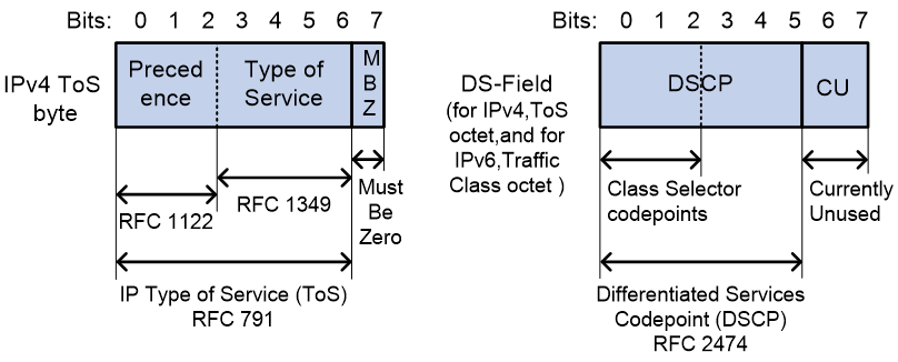
As shown in Figure 8, the ToS field in the IP header contains 8 bits. The first 3 bits (0 to 2) represent IP precedence from 0 to 7. According to RFC 2474, the ToS field is redefined as the differentiated services (DS) field. A DSCP value is represented by the first 6 bits (0 to 5) of the DS field and is in the range 0 to 63. The remaining 2 bits (6 and 7) are reserved.
Table 6 IP precedence
|
IP precedence (decimal) |
IP precedence (binary) |
Description |
|
0 |
000 |
Routine |
|
1 |
001 |
priority |
|
2 |
010 |
immediate |
|
3 |
011 |
flash |
|
4 |
100 |
flash-override |
|
5 |
101 |
critical |
|
6 |
110 |
internet |
|
7 |
111 |
network |
Table 7 DSCP values
|
DSCP value (decimal) |
DSCP value (binary) |
Description |
|
46 |
101110 |
ef |
|
10 |
001010 |
af11 |
|
12 |
001100 |
af12 |
|
14 |
001110 |
af13 |
|
18 |
010010 |
af21 |
|
20 |
010100 |
af22 |
|
22 |
010110 |
af23 |
|
26 |
011010 |
af31 |
|
28 |
011100 |
af32 |
|
30 |
011110 |
af33 |
|
34 |
100010 |
af41 |
|
36 |
100100 |
af42 |
|
38 |
100110 |
af43 |
|
8 |
001000 |
cs1 |
|
16 |
010000 |
cs2 |
|
24 |
011000 |
cs3 |
|
32 |
100000 |
cs4 |
|
40 |
101000 |
cs5 |
|
48 |
110000 |
cs6 |
|
56 |
111000 |
cs7 |
|
0 |
000000 |
be (default) |
802.1p priority
802.1p priority lies in the Layer 2 header. It applies to occasions where Layer 3 header analysis is not needed and QoS must be assured at Layer 2.
Figure 9 An Ethernet frame with an 802.1Q tag header
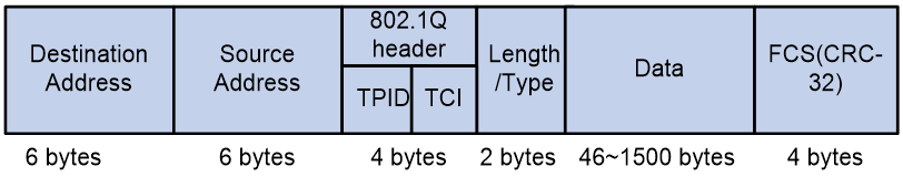
As shown in Figure 9, the 4-byte 802.1Q tag header contains the 2-byte tag protocol identifier (TPID) and the 2-byte tag control information (TCI). The value of the TPID is 0x8100. Figure 10 shows the format of the 802.1Q tag header. The Priority field in the 802.1Q tag header is called 802.1p priority, because its use is defined in IEEE 802.1p. Table 8 shows the values for 802.1p priority.
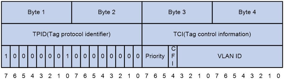
Table 8 Description on 802.1p priority
|
802.1p priority (decimal) |
802.1p priority (binary) |
Description |
|
0 |
000 |
best-effort |
|
1 |
001 |
background |
|
2 |
010 |
spare |
|
3 |
011 |
excellent-effort |
|
4 |
100 |
controlled-load |
|
5 |
101 |
video |
|
6 |
110 |
voice |
|
7 |
111 |
network-management |
802.11e priority
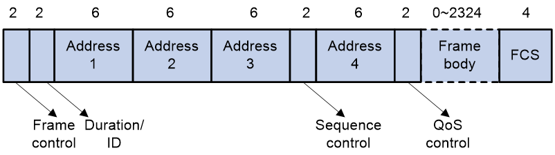
To provide QoS services on WLAN, the 802.11e standard was developed. IEEE 802.11e is a MAC-layer enhancement to IEEE 802.11. IEEE 802.11e adds a 2-byte QoS control field to the 802.11e MAC frame header. The 3-bit QoS control field represents the 802.11e priority in the range of 0 to 7.
Figure 11 802.11e frame structure