- Table of Contents
- Related Documents
-
| Title | Size | Download |
|---|---|---|
| 01-GRE over IPv4 Tunnel Configuration Examples | 94.38 KB |
GRE over IPv4 Tunnel Configuration Examples
Copyright © 2024 New H3C Technologies Co., Ltd. All rights reserved.
No part of this manual may be reproduced or transmitted in any form or by any means without prior written consent of New H3C Technologies Co., Ltd.
Except for the trademarks of New H3C Technologies Co., Ltd., any trademarks that may be mentioned in this document are the property of their respective owners.
The information in this document is subject to change without notice.
Introduction
The following information provides GRE over IPv4 (GRE/IPv4) tunnel configuration examples.
Prerequisites
The following information applies to Comware 7-based routers. Procedures and information in the examples might be slightly different depending on the software or hardware version of the routers.
The configuration examples were created and verified in a lab environment, and all the devices were started with the factory default configuration. When you are working on a live network, make sure you understand the potential impact of every command on your network.
The following information is provided based on the assumption that you have basic knowledge of GRE.
Example: Setting up an GRE/IPv4 tunnel
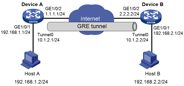
Network configuration
As shown in Figure 1, Device A and Device B use fixed IP addresses to connect to the Internet. Establish an IPv4 over IPv4 GRE tunnel between Device A and Device B, so Host A and Host B in private networks can communicate with each other across the Internet.
Restrictions and guidelines
Make sure Device A and Device B have connected to the Internet, and GigabitEthernet 1/0/2 on Device A and GigabitEthernet 1/0/2 on Device B have IPv4 connectivity.
Procedures
Configuring Device A
# Configure an IP address for interface GigabitEthernet 1/0/1.
<DeviceA> system-view
[DeviceA] interface gigabitethernet 1/0/1
[DeviceA-GigabitEthernet1/0/1] ip address 192.168.1.1 255.255.255.0
[DeviceA-GigabitEthernet1/0/1] quit
# Configure an IP address for interface GigabitEthernet 1/0/2.
[DeviceA] interface gigabitethernet 1/0/2
[DeviceA-GigabitEthernet1/0/2] ip address 1.1.1.1 255.255.255.0
[DeviceA-GigabitEthernet1/0/2] quit
# Create tunnel interface Tunnel 0, and specify the tunnel mode as GRE/IPv4.
[DeviceA] interface tunnel 0 mode gre
# Assign an IP address to interface Tunnel 0.
[DeviceA-Tunnel0] ip address 10.1.2.1 255.255.255.0
# Configure the source address of interface Tunnel 0 as the IP address of GigabitEthernet 1/0/2 on Device A.
[DeviceA-Tunnel0] source 1.1.1.1
# Configure the destination address of interface Tunnel 0 as the IP address of GigabitEthernet 1/0/2 on Device B.
[DeviceA-Tunnel0] destination 2.2.2.2
[DeviceA-Tunnel0] quit
# Configure a static route from Device A through interface Tunnel 0 to the subnet where Host B resides.
[DeviceA] ip route-static 192.168.2.0 255.255.255.0 Tunnel 0
Configuring Device B
# Configure an IP address for interface GigabitEthernet 1/0/1.
<DeviceB> system-view
[DeviceB] interface gigabitethernet 1/0/1
[DeviceB-GigabitEthernet1/0/1] ip address 192.168.2.1 255.255.255.0
[DeviceB-GigabitEthernet1/0/1] quit
# Configure an IP address for interface GigabitEthernet 1/0/2.
[DeviceB] interface gigabitethernet 1/0/2
[DeviceB-GigabitEthernet1/0/2] ip address 2.2.2.2 255.255.255.0
[DeviceB-GigabitEthernet1/0/2] quit
# Create tunnel interface Tunnel 0, and specify the tunnel mode as GRE/IPv4.
[DeviceB] interface tunnel 0 mode gre
# Assign an IP address to interface Tunnel 0.
[DeviceB-Tunnel0] ip address 10.1.2.2 255.255.255.0
# Configure the source address of interface Tunnel 0 as the IP address of GigabitEthernet 1/0/2 on Device B.
[DeviceB-Tunnel0] source 2.2.2.2
# Configure the destination address of interface Tunnel 0 as the IP address of GigabitEthernet 1/0/2 on Device A.
[DeviceB-Tunnel0] destination 1.1.1.1
[DeviceB-Tunnel0] quit
# Configure a static route from Device B through Tunnel 0 to the subnet where Host A resides.
[DeviceB] ip route-static 192.168.1.0 255.255.255.0 Tunnel 0
Verifying the configuration
# Verify that Host A can ping Host B.
C:\Users> ping 192.168.2.2
Pinging 192.168.2.2 with 32 bytes of data:
Reply from 192.168.2.2: bytes=32 time=19ms TTL=253
Reply from 192.168.2.2: bytes=32 time<1ms TTL=253
Reply from 192.168.2.2: bytes=32 time<1ms TTL=253
Reply from 192.168.2.2: bytes=32 time<1ms TTL=253
Ping statistics for 192.168.2.2:
Packets: Sent = 4, Received = 4, Lost = 0 (0% loss),
Approximate round trip times in milli-seconds:
Minimum = 0ms, Maximum = 19ms, Average = 4ms
Configuration files
· Device A
#
interface GigabitEthernet1/0/1
ip address 192.168.1.1 255.255.255.0
#
interface GigabitEthernet1/0/2
ip address 1.1.1.1 255.255.255.0
#
interface Tunnel0 mode gre
source 1.1.1.1
destination 2.2.2.2
ip address 10.1.2.1 255.255.255.0
#
ip route-static 192.168.2.0 255.255.255.0 Tunnel 0
#
· Device B
#
interface GigabitEthernet1/0/1
ip address 192.168.2.1 255.255.255.0
#
interface GigabitEthernet1/0/2
ip address 2.2.2.2 255.255.255.0
#
interface Tunnel0 mode gre
source 2.2.2.2
destination 1.1.1.1
ip address 10.1.2.2 255.255.255.0
#
ip route-static 192.168.1.0 255.255.255.0 Tunnel 0
#