- Table of Contents
-
- H3C S10500X Switch Series Installation Guide-6W108
- 00-Preface
- 01-Chapter 1 Preparing for Installation
- 02-Chapter 2 Installing the Switch in a rack
- 03-Chapter 3 Installing FRUs
- 04-Chapter 4 Connecting Your Switch to the Network
- 05-Chapter 5 Replacement Procedures
- 06-Appendix A Engineering Labels for Cables
- 07-Appendix B Cable Management
- 08-Appendix C LEDs
- 09-Appendix D Repackaging the Switch
- Related Documents
-
| Title | Size | Download |
|---|---|---|
| 08-Appendix C LEDs | 440.52 KB |
8 Appendix C LEDs
Table 8-1 LEDs at a glance
|
LEDs |
|
|
· Management Ethernet port LEDs |
|
MPU LEDs
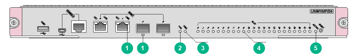
The LSUM1SUPXD0 and LSUM1SUPXES0 MPUs have similar LEDs. Figure8-1 illustrates the LSUM1SUPXD0 MPU LEDs.
Figure8-1 LSUM1SUPXD0 MPU LEDs
|
(1) Management Ethernet port LEDs |
(2) Fan tray status LED (FAN) |
|
(3) Power module status LED (PWR) |
(4) Card status LEDs |
|
(5) MPU active/standby status LED (ACTIVE) |
|
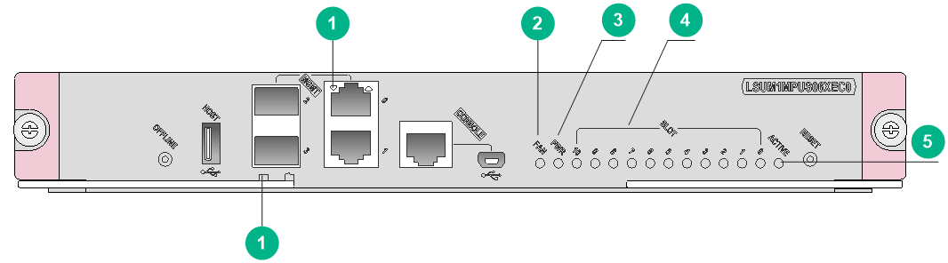
The LSUM1MPUS06XEB0, LSUM1MPUS10XEA0, LSUM1MPUS10XEC0, LSUM1MPUS10XE0 and LSUM1MPUS06XEC0 MPUs have similar LEDs. Figure8-2 illustrates the LSUM1MPUS06XEC0 MPU LEDs.
Figure8-2 LSUM1MPUS06XEC0 MPU LEDs
|
(1) Management Ethernet port LEDs |
(2) Fan tray status LED (FAN) |
|
(3) Power module status LED (PWR) |
(4) Card status LEDs |
|
(5) MPU active/standby status LED (ACTIVE) |
|
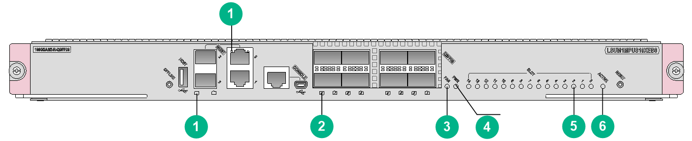
Figure8-3 LSUM1MPUS10XEB0 MPU LEDs
|
(1) Management Ethernet port LEDs |
(2) QSFP28 port LED |
|
|
(3) Fan tray status LED (FAN) |
(4) Power module status LED (PWR) |
|
|
(5) Card status LEDs |
(6) MPU active/standby status LED (ACTIVE) |
|
Management Ethernet port LEDs
RJ-45 management Ethernet port LEDs
A pair of LEDs LINK and ACT is provided for an RJ-45 management Ethernet port to indicate the port link status and data forwarding status.
Table 8-2 RJ-45 management Ethernet port LED description
|
LINK LED status |
ACT LED status |
Description |
|
On |
Flashing |
A link is present, and the port is receiving or sending data. |
|
On |
Off |
A link is present. |
|
Off |
Off |
No link is present. |
SFP management Ethernet port LEDs
A LED is provided for an SFP management Ethernet port to indicate the port link status and data forwarding status.
Table 8-3 SFP management Ethernet port LED description
|
LED status |
Description |
|
Flashing green |
A link is present, and the port is receiving or sending data. |
|
Steady green |
A link is present. |
|
Off |
No link is present. |
Fan tray status LED
The FAN LED indicates the operating state of the fan trays.
Table 8-4 Fan tray LED description
|
LED mark |
LED status |
Description |
|
FAN |
Steady green |
The fan trays are operating correctly. |
|
Steady red |
A fan tray problem has occurred, or a fan tray is not present. |
|
|
Off |
The switch is not powered on. |
Power module status LED
The PWR LED indicates the operating state of the power modules.
Table 8-5 Power status LED description
|
LED mark |
LED status |
Description |
|
PWR |
Steady green |
The power modules are operating correctly. |
|
Steady red |
A power module problem has occurred, or no power module is present. |
|
|
Off |
The switch is not powered on. |
Card status LEDs
A LED is provided for each slot (the LED numbered the same as the slot) to indicate the status of the active MPU, standby MPU, service module, or switching fabric module in the slot.
|
|
NOTE: On an S10508X-V switch, slot numbers are marked on top of the slots. |
Table 8-6 Card status LED description
|
LED status |
Description |
|
Flashing green (0.5 Hz) |
The card is operating correctly. |
|
Flashing red (4 Hz) |
The service module or switching fabric module is loading software. If the LED flashes continuously, the card is not compatible with the system software version. |
|
Flashing red (0.25 Hz) |
The card temperature exceeds the upper warning or alarm threshold or falls below the lower threshold. |
|
Steady red |
The card is faulty. |
|
Off |
No power is supplied to the card, or the card is not present. |
|
|
NOTE: Before the active MPU starts up, all card status LEDs are off. The tables describe the card LED status after the active MPU starts up. |
MPU active/standby state LED
The ACTIVE LED indicates the active or standby operating mode of the MPU.
Table 8-7 MPU active/standby state LED description
|
LED mark |
LED Status |
Description |
|
ACTIVE |
On |
The MPU is operating in active mode. |
|
Off |
· The MPU is operating in standby mode. · The MPU is faulty. Examine also the status LED for the MPU to determine whether a fault has occurred. |
QSFP28 port LEDs
An LSUM1MPUS10XEB0 MPU provides a LED for each QSFP28 port to indicate their link status and data sending and receiving status.
Table 8-8 QSFP28 port LED description
|
LED status |
Description |
|
Flashing |
The QSFP28 port is sending or receiving data. |
|
On |
A link is present on the QSFP28 port. |
|
Off |
No link is present on the QSFP28 port. |
Service module LEDs
RJ-45 Ethernet port LEDs
Table 8-9 RJ-45 Ethernet port LED description
|
LED status |
Description |
|
Flashing yellow |
The Ethernet port is receiving or sending data at 100/1000 Mbps. |
|
Flashing green |
The Ethernet port is receiving or sending data at 10 Gbps. |
|
Steady yellow |
A 100/1000 Mbps link is present. |
|
Steady green |
A 10 Gbps link is present. |
|
Off |
No link is present. |
SFP port LEDs
Table 8-10 SFP port LED description
|
Status |
Description |
|
Flashing |
The SFP port is receiving or sending data. |
|
On |
A link is present. |
|
Off |
No link is present. |
SFP+ port LEDs
The service modules provide a LED for each SFP+ port to indicate their link status and data receiving/forwarding status.
Table 8-11 SFP+ port LED description
|
Status |
Description |
|
Flashing yellow |
The SFP+ port is receiving or sending data at 100/1000 Mbps. |
|
Flashing green |
The SFP+ port is receiving or sending data at 10 Gbps. |
|
Steady yellow |
A 100/1000 Mbps link is present. |
|
Steady green |
A 10 Gbps link is present. |
|
Off |
No link is present. |
SFP28 port LEDs
The service modules provide a LED for each SFP28 port to indicate their link status and data receiving/forwarding status.
Table 8-12 SFP28 port LED description
|
Status |
Description |
|
Flashing |
The SFP28 port is receiving or sending data. |
|
On |
A link is present. |
|
Off |
No link is present. |
QSFP+ port LEDs
The service modules provide a LED for each QSFP+ port to indicate their link status and data receiving/forwarding status.
Table 8-13 QSFP+ port LED description
|
Status |
Description |
|
Flashing |
The QSFP+ port is receiving or sending data. |
|
On |
A link is present, but no data is being received or sent. |
|
Off |
No link is present. |
|
|
NOTE: The color of the QSFP+ port LED indicates support of the port for 100-GE/40-GE switchover as follows: · Yellow—The port supports 100-GE/40-GE switchover. · Green—The port does not support 100-GE/40-GE switchover. |
QSFP28 port LEDs
The service modules provide a LED for each QSFP28 port to indicate their link status and data receiving/forwarding status.
Table 8-14 QSFP28 port LED description
|
Status |
Description |
|
Flashing |
The QSFP28 port is receiving or sending data. |
|
On |
A link is present, but no data is being received or sent. |
|
Off |
No link is present. |
|
|
NOTE: The color of the QSFP28 port LED indicates the port speed as follows: · Green—100 Gbps. · Yellow—Less than 100 Gbps. |
Switching fabric module LEDs
The LSU1FAB08XE0 switching fabric module uses a pair of RUN and ALM LEDs to indicate its operating status. The LSUM1FAB06XEC0, LSUM1FAB06XEB0, LSUM1FAB08XEB0, LSUM1FAB10XE0, LSUM1FAB10XEA0, LSUM1FAB10XEC0, and LSUM1FAB16XD0 switching fabric modules each use a RUN/ALM/OFL LED to indicate their operating status. See Table 8-16 for the LED description.
Table 8-15 Switching fabric module LED description (1)
|
RUN LED status |
ALM LED status |
Description |
|
Flashing (0.5 Hz) |
Off |
The switching fabric module is operating correctly. |
|
Off |
Off |
The switching fabric module is not present or is starting up. |
|
Off |
On |
The switching fabric module is faulty. |
|
Flashing (0.5 Hz) |
Flashing (0.25 Hz) |
The temperature of the switching fabric module has exceeded the upper or lower limit. |
|
On |
Off or flashing (0.25 Hz) |
The switching fabric module is in offline state. |
Table 8-16 Switching fabric module LED description (2)
|
LED mark |
LED Status |
Description |
|
RUN/ALM/OFL |
Off |
No switching fabric module is present, or the switching fabric module is not powered on. |
|
Steady green |
The switching fabric module is in offline state. |
|
|
Flashing green (0.5 Hz) |
The switching fabric module is operating correctly. |
|
|
Steady red |
The switching fabric module has reported a major alarm or is faulty. |
|
|
Flashing red (0.25 Hz) |
The switching fabric module has reported a minor alarm, such as temperature alarm. |
|
|
IMPORTANT: · A switching fabric module goes offline after you isolate it or press the OFFLINE button on it. · The OFFLINE button on a switching fabric module is intended for debugging and locating failures by technical support. As a best practice, do not use it without authorization. |
Fan tray LEDs
Each fan tray of the S10506X, S10508X, S10508X-V, and S10510X switches uses a pair of LEDs OK and FAIL to indicate its operating status.
Table 8-17 Fan tray LED description
|
OK LED status |
FAIL LED status |
Description |
|
On |
Off |
The fan tray is operating correctly. |
|
Off |
On |
The fan tray is faulty. |
|
Off |
Off |
The fan tray is not operating. |
Each S10516X fan tray uses an OK/FAIL LED to indicate its operating status.
Table 8-18 S10516X fan tray LED description
|
LED (OK/FAIL) status |
Description |
|
Steady green |
The fan tray is operating correctly. |
|
Steady red |
The fan tray is faulty. |
|
Off |
The fan tray is not operating. |
Power module LEDs
The LSUM1AC1200, LSUM1AC2500, and LSUM1DC2400 power modules are available for the switch.
The LSUM1AC1200 and LSUM2AC2500 power modules each use two LEDs AC and DC to indicate their operating status.
The LSUM1DC2400 power module uses two LEDs INP OK and DC/FLT to indicate its operating status.
Table 8-19 LED description for the LSUM1AC1200 and LSUM1AC2500 power modules
|
LED |
Color |
Description |
|
AC |
Off |
· The power module has no power input. · The input voltage is too low, and the power module is in self-protection state. |
|
Green |
The power input is normal. |
|
|
DC |
Green |
The power module is outputting power normally. |
|
Red |
A power output fault has occurred, for example, output short-circuit, output overcurrent, output overvoltage, input undervoltage, or remote power off. The power module has entered self-protection state. |
|
|
Orange |
An overtemperature condition has occurred and the power module has entered self-protection state. |
Table 8-20 LSUM1DC2400 power module LED description
|
LED |
Color |
Description |
|
INP OK |
Off |
· The power module has no power input. · The input voltage is too low, and the power module is in self-protection state. |
|
Green |
The power input is normal. |
|
|
DC/FLT |
Green |
The power module is outputting power normally. |
|
Red |
A power output fault has occurred, for example, output short-circuit, output overcurrent, output overvoltage, input undervoltage, or remote power off. The power module has entered self-protection state. |
|
|
Orange |
An overtemperature condition has occurred, and the power module has entered self-protection state. |
