- Table of Contents
-
- H3C S10500X Switch Series Installation Guide-6W108
- 00-Preface
- 01-Chapter 1 Preparing for Installation
- 02-Chapter 2 Installing the Switch in a rack
- 03-Chapter 3 Installing FRUs
- 04-Chapter 4 Connecting Your Switch to the Network
- 05-Chapter 5 Replacement Procedures
- 06-Appendix A Engineering Labels for Cables
- 07-Appendix B Cable Management
- 08-Appendix C LEDs
- 09-Appendix D Repackaging the Switch
- Related Documents
-
| Title | Size | Download |
|---|---|---|
| 05-Chapter 5 Replacement Procedures | 4.39 MB |
Contents
Replacing the air filter for an S10506X or S10510X switch
Replacing an air filter for an S10508X switch
Replacing an air filter for an S10508X-V switch
Replacing a transceiver module or network cable
Replacing an SFP+/SFP/SFP28/QSFP+/QSFP28 transceiver module
5 Replacement procedures
|
|
CAUTION: · Ensure electrical safety when you hot swap an FRU. · To avoid bodily injury and device damage, strictly follow the replacement procedure in this section when you replace a component. · As a best practice to avoid data theft, remove all data from an FRU that has a storage medium, for example, a disk or flash before disposal of that FRU. To remove data, format or destroy the storage medium on the FRU. |
The switch uses a modular, hot-swappable architecture, and supports field replaceable units (FRUs). You can replace any FRU when the switch is operating.
Replacing a power module
Follow these guidelines when you replace a power module:
· Strictly follow the procedures shown in Figure 5-1 and Figure 5-2 to replace a power module to avoid device damage or bodily injury.
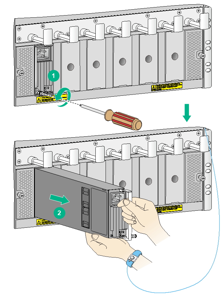
Figure 5-1 Power module removal procedure
![]()
Figure 5-2 Power module installation procedure
![]()
· Power modules on the switch must be the same model. When the new power modules and the existing power modules are not the same model, power off the switch and remove all existing power modules before installing new power modules.
· Provide a circuit breaker for each power module. Before replacing a power module, turn off its circuit breaker.
· The power module might be of high temperature. Remove it with caution.
· To install the removed power module in the chassis again, install it after the status LED on it is off.
· After removing the power module from a slot, install a filler panel in the slot if you do not install a new power module.
To replace a power module:
1. Prepare an antistatic mat to place the removed power module.
2. Turn off the circuit breaker.
3. Wear an ESD wrist strap and make sure it makes good skin contact and is reliably grounded. For more information, see "Attaching an ESD wrist strap."
4. Remove the power cord plug from the power module.
¡ AC power cord: Remove the cable ties from the power cord, and remove the power cord plug from the power module.
¡ DC power cord: Remove the cable ties from the power cord, loosen the captive screw on the power cord plug, and remove the plug from the power module.
5. Use a Phillips screwdriver to loosen the captive screw on the power module, and then grasp the captive screw between your thumb and index finger to carefully pull out the handle on the power module.
6. Holding the power module handle with one hand and supporting the bottom of the power module with the other, gently pull the power module out.
7. Put the removed power module on the antistatic mat.
8. Install a new power module. For the installation procedures, see "Installing a power module."
Figure 5-3 Removing an AC power module
Replacing a card
|
|
CAUTION: · To remove the only MPU on the switch, first power off the switch. · Before you remove an MPU or service module, remove the cables from it. · Before you install the removed card again, make sure the status LED on it is off. · Install a filler panel in the slot where you are not to install a card. · To remove a switching fabric module or standby MPU, first press the OFFLINE button (if any) on it. · Do not press the OFFLINE button on the active MPU. |
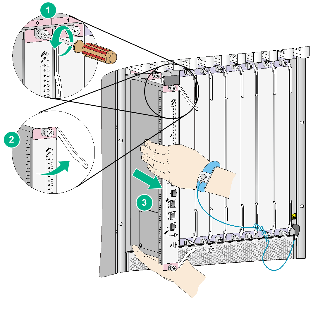
The replacement procedure is similar for cards installed in vertical or horizontal slots. The following replaces a card installed in a vertical slot.
To replace a card:
1. Prepare an antistatic mat to place the removed card.
2. Wear an ESD wrist strap and make sure it makes good skin contact and is reliably grounded. For more information, see "Attaching an ESD wrist strap."
3. Use a Phillips screwdriver to remove the captive screws on the card.
4. Press the ejector buttons on the ejector levers to release the ejector levers. (This step is applicable only to a switching fabric module with ejector buttons on the ejector levers.)
5. Simultaneously open the ejector levers on the card to separate the card from the backplane.
6. Use one hand to slowly move the card outwards. Supporting the bottom of the card with the other hand, pull the card out of the slot along slide rails.
7. Put the removed card on the antistatic mat.
8. Install a new card. For the installation procedures, see "Installing a card."
Replacing a fan tray
|
|
CAUTION: · To avoid bodily injury, do not touch the rotating fans when replacing a fan tray. · To ensure good ventilation, install a new fan tray within two minutes after removing the old one. · To install only one fan tray on an S10506X, S10508X, S10508X-V, or S10510X switch, install it in slot FAN0. · To install fan trays in slots FAN 10 to FAN 14 on an S10516X switch, orient the fan tray with the yellow warning sign above the handle. To install fan trays in other slots on the switch, orient the fan tray with the yellow warning sign below the handle. |
The S10508X-V switch provides horizontal fan tray slots. The S10506X, S10508X, S10510X, and S10516X switches provide vertical fan tray slots.
The fan tray installation procedure is similar for horizontal and vertical slots. The following procedure uses the S10508X-V switch as an example.
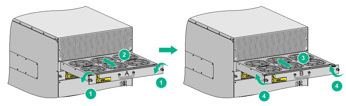
To replace a fan tray:
1. Prepare an antistatic mat to place the fan tray to be removed.
2. Put on an ESD wrist strap and make sure the wrist strap makes good skin contact and is reliably grounded. For more information, see "Attaching an ESD wrist strap."
3. Loosen the captive screws on the fan tray.
4. Hold the handle of the fan tray with one hand to gently pull the fan tray part way out of the chassis. After the fans stop rotating, support the bottom of the fan tray with the other hand, and take out the fan tray from the chassis.
5. Put the removed fan tray on the antistatic mat.
6. Install a new fan tray in the slot. For the installation procedure, see "Installing fan trays."
Figure 5-5 Replacing a fan tray
|
(A) Fan tray to be removed |
(B) Fan tray to be installed |
Replacing an air filter
|
|
CAUTION: Clean air filters every three months to guarantee adequate ventilation and avoid over-temperature. |
The S10506X and S10510X switches each have one air filter, installed at the left side of the chassis.
The S10508X switch has two air filters, installed at the left side of the chassis.
The S10508X-V switch has three air filters, one installed over the air inlet vents on the left of the power module section, one installed over the air inlet vents on the right of the power module section, and one installed above the power module section.
The S10516X switch does not support air filters.
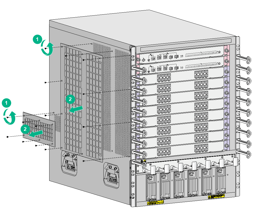
Replacing the air filter for an S10506X or S10510X switch
The air filter replacement procedure is similar for the S10506X and S10510X switches. This section replaces an air filter for an S10506X switch.
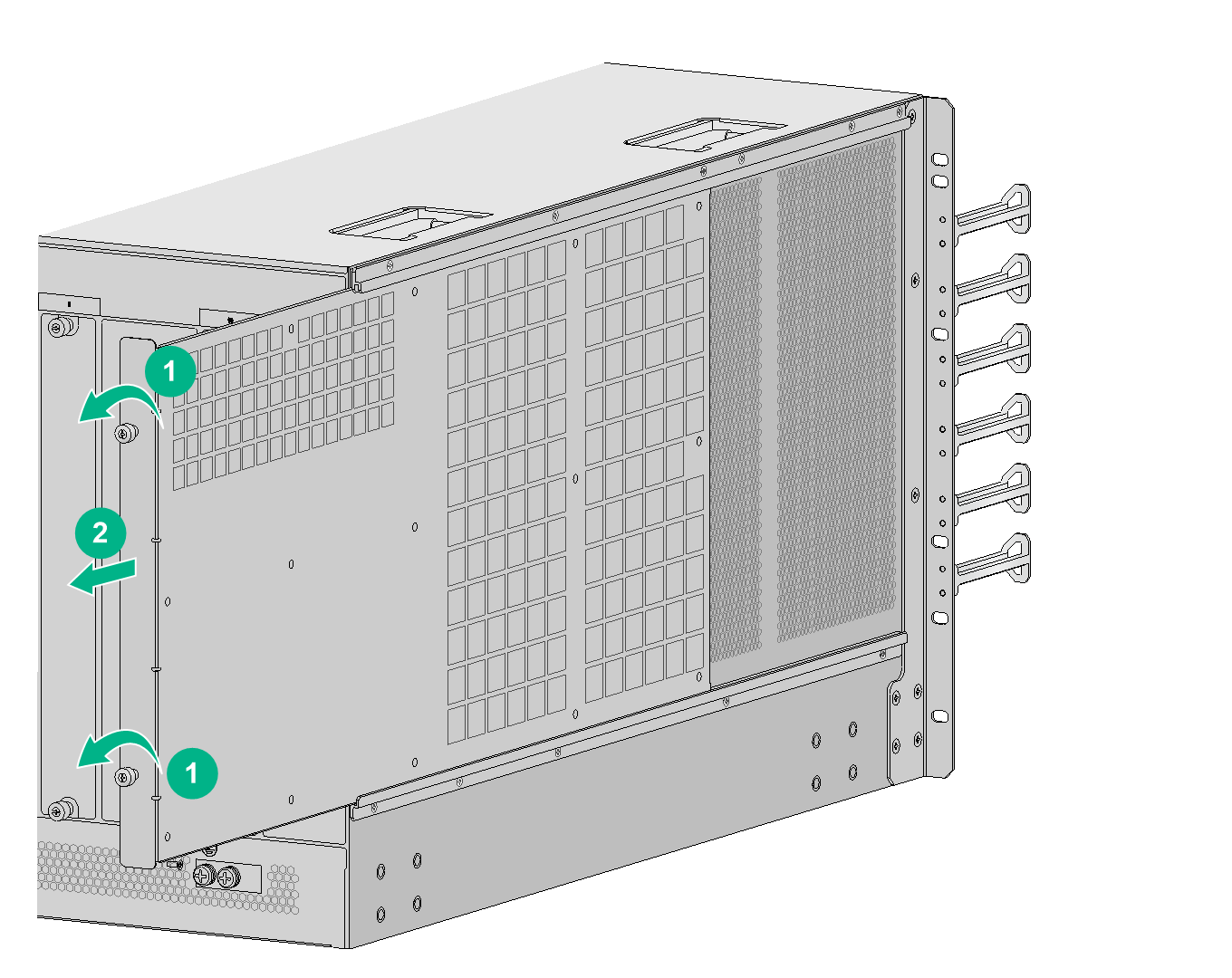
To replace the air filter for an S10506X switch:
1. Loosen the captive screws on the air filter, as shown by callout 1 in Figure 5-6.
Keep the removed screws secure for future use.
2. Hold the captive screws to slowly pull the air filter out, as shown by callout 2 in Figure 5-6.
3. Clean the air filter and reinstall it. For the installation procedure, see "Installing air filters for an S10506X or S10510X switch."
Figure 5-6 Removing the air filter from an S10506X switch
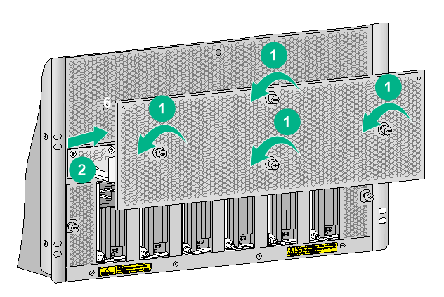
Replacing an air filter for an S10508X switch
1. Remove the screws on the air filter, as shown by callout 1 in Figure 5-7.
Keep the removed screws secure for future use.
2. Remove the air filter from the chassis.
3. Clean the air filter and reinstall it. For the installation procedure, see "Installing air filters for an S10508X switch."
Figure 5-7 Removing air filters from an S10508X switch
Replacing an air filter for an S10508X-V switch
Replacing the air filter above the power module section
1. Loosen the captive screws on the air filter, as shown by callout 1 in Figure 5-8.
2. Remove the air filter from the chassis.
3. Clean the air filter and reinstall it above the power module section. For the installation procedure, see "Installing air filters for an S10508X-V switch."
Figure 5-8 Removing the air filter above the power module section
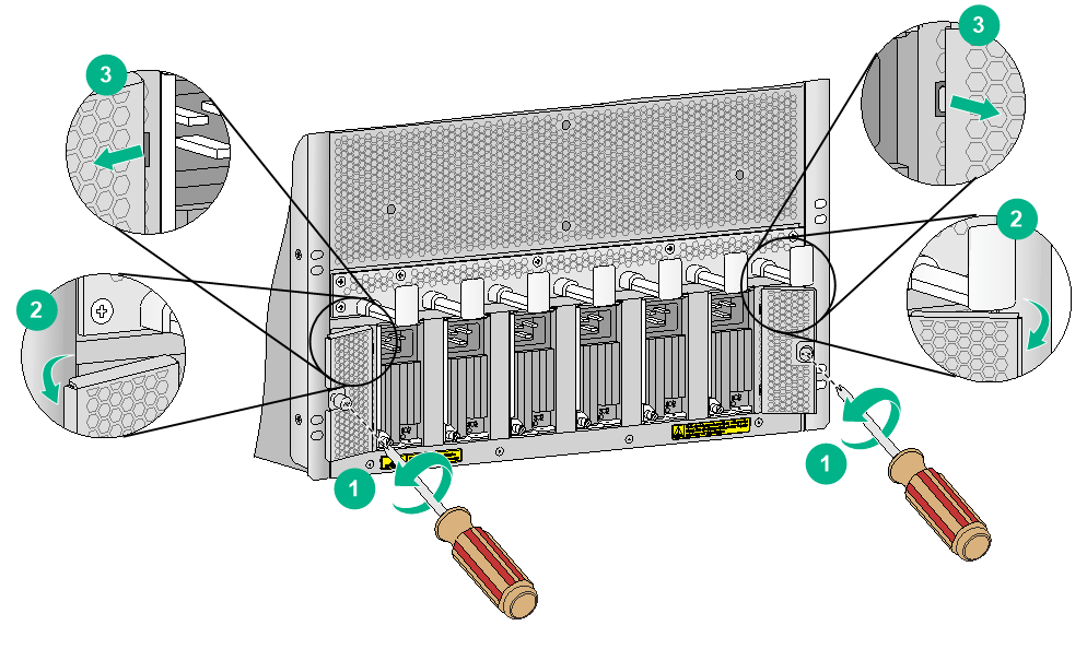
Replacing the air filter on the left or right of the power module section
1. Loosen the captive screw on the air filter, as shown by callout 1 in Figure 5-9.
2. Open the air filter from the chassis.
3. Remove the pegs on the air filter from the peg holes in the chassis.
4. Clean the air filter and reinstall it on the switch. For the installation procedure, see "Installing air filters for an S10508X-V switch."
Figure 5-9 Removing the air filters on the left and right of the power module section
Replacing a transceiver module or network cable
|
|
WARNING! Disconnected optical fibers or transceiver modules might emit invisible laser light. Do not stare into beams or view directly with optical instruments when the switch is operating. |
Use tweezers provided with the switch to remove a transceiver module or optical fiber on an S10508X, S10508X-V, or S10516X switch in case of limited space.
Replacing an SFP+/SFP/SFP28/QSFP+/QSFP28 transceiver module
|
|
CAUTION: · Do not touch the golden plating on a transceiver module during the removal process. · After removing a transceiver module, you must wait a minimum of 5 seconds before installing a new transceiver module. · Make sure the new transceiver module is the same model as the peer transceiver module at the other end of the optical fiber. |
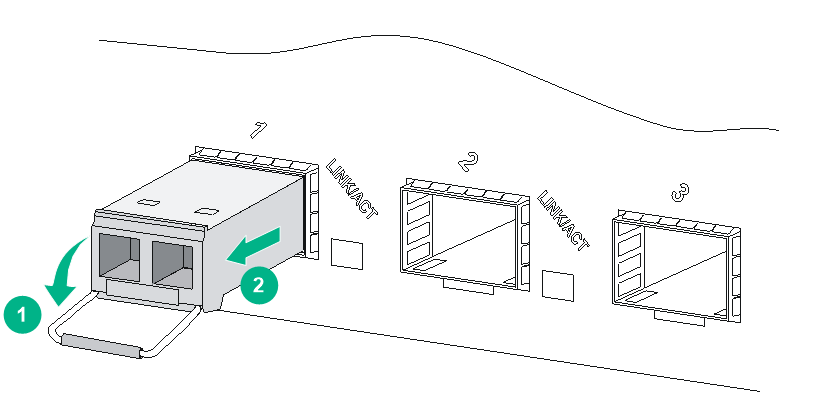
The replacement procedure is similar for SFP+, SFP, SFP28, QSFP+, and QSFP28 transceiver modules. The following procedure replaces an SFP+ transceiver module.
To replace an SFP+ transceiver module:
1. Wear an ESD wrist strap and make sure it makes good skin contact and is reliably grounded.
For more information, see "Attaching an ESD wrist strap."
2. Remove the optical fibers from the transceiver module.
There is a latching mechanism between a fiber connector and transceiver module port to prevent connector disengagement. Release the latching before removing the optical fiber. To avoid damages, do not use excessive force.
3. Pivot the bail latch down to the horizontal position.
For a QSFP+ or QSFP28 transceiver module that uses a plastic pull latch, skip this step.
4. Hold the bail latch to pull the transceiver module out of the slot. Make sure you apply force in the direction parallel to the ground. To avoid damaging the bail latch, do not use excessive force.
If you apply force at an angle when pulling the transceiver module out, you can hardly pull the transceiver module out and the transceiver module or fiber port might be damaged.
5. Insert the dust plugs into the removed transceiver module, and put the transceiver module into its packaging bag.
6. Install a new transceiver module. For the installation procedure, see "Installing an SFP+/SFP/SFP28/QSFP+/QSFP28 transceiver module."
Figure 5-10 Removing an SFP+ transceiver module
Replacing a network cable
|
|
CAUTION: · Do not touch the golden plating on the two modular ends of a network cable during the replacement process. · Make sure the two modular ends of the new network cable are compatible with the ports into which they will be inserted. · To avoid network cable damage and signal loss, do not strain or tangle a network cable. · Before inserting a modular end of a network cable into a port, make sure the module aligns with the port correctly. · If a network cable cannot be removed or installed, verify that the removal or installation procedure is correct. Do not use excessive force. |
The replacement procedure is the same for network cables. The following procedure replaces an SFP+ DAC cable.
To replace an SFP+ DAC cable:
1. Wear an ESD wrist strap and make sure it makes good skin contact and is reliably grounded. For more information, see "Attaching an ESD wrist strap."
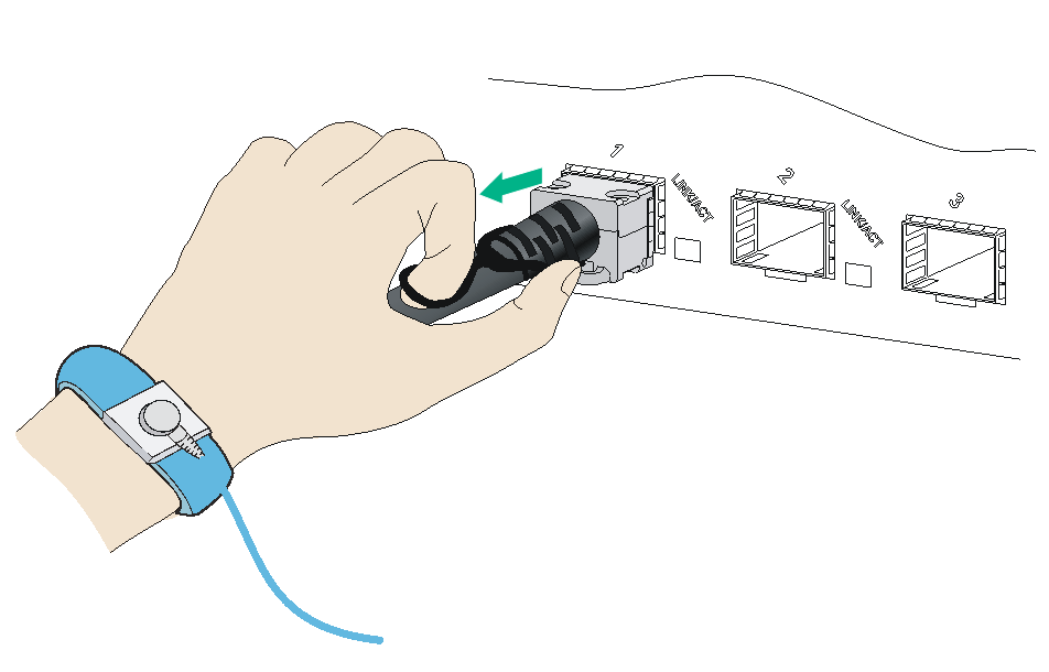
2. Push the modular end of the cable gently inward to release the latching mechanism. Then use the pull ring on the cable to pull the modular end out of the slot. Make sure you apply force in the direction parallel to the ground. If you apply force at an angle. To avoid damaging the pull ring, do not use excessive force.
If you apply force at an angle when pulling the module out, you can hardly pull the network cable out and the network cable or fiber port might be damaged.
Figure 5-11 Removing an SFP+ DAC cable
3. Install a new cable. For the installation procedures, see "Connecting a network cable."
