- Table of Contents
-
- H3C S10500X Switch Series Installation Guide-6W108
- 00-Preface
- 01-Chapter 1 Preparing for Installation
- 02-Chapter 2 Installing the Switch in a rack
- 03-Chapter 3 Installing FRUs
- 04-Chapter 4 Connecting Your Switch to the Network
- 05-Chapter 5 Replacement Procedures
- 06-Appendix A Engineering Labels for Cables
- 07-Appendix B Cable Management
- 08-Appendix C LEDs
- 09-Appendix D Repackaging the Switch
- Related Documents
-
| Title | Size | Download |
|---|---|---|
| 03-Chapter 3 Installing FRUs | 1.97 MB |
(Optional) Installing transceiver modules and network cables
Installing an SFP+/SFP/SFP28/QSFP+/QSFP28 transceiver module
3 Installing FRUs
Attaching an ESD wrist strap
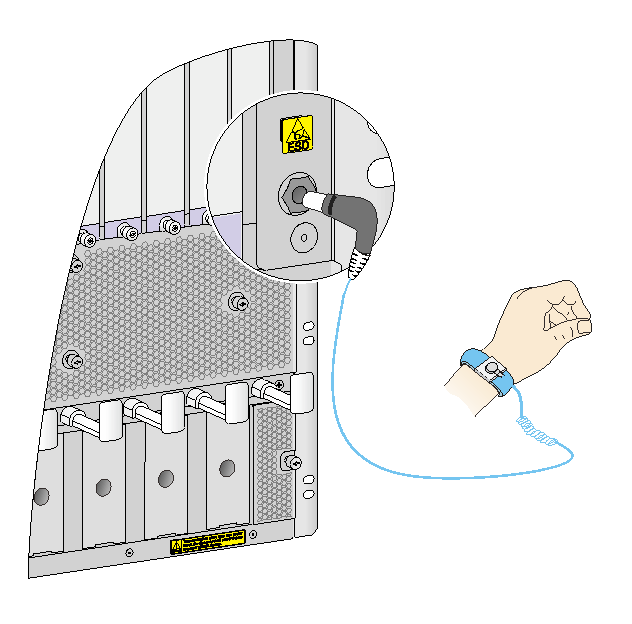
Every S10500X switch provides an ESD wrist strap. To minimize ESD damage to electronic components, wear the ESD wrist strap and make sure it is reliably grounded when installing modules.
To use an ESD wrist strap:
1. Make sure the switch is reliably grounded. For how to ground your switch, see "Grounding the switch."
2. Put on the wrist strap.
3. Tighten the wrist strap to make sure it makes good skin contact.
Make sure the resistance reading between your body and the ground is between 1 and 10 megohms.
4. As shown in Figure 3-1, insert the ESD wrist strap into the ESD socket (with an ESD sign) on the switch chassis, or attach it to the grounding screw of the chassis with an alligator clip.
Figure 3-1 Attaching an ESD wrist strap
Installing a card
|
|
IMPORTANT: · Before installing a card in the chassis, make sure the connectors on the card are not broken or blocked to avoid damaging the backplane. · To ensure good ventilation, install a filler panel in an empty slot. · Before you install a card that has a protection box, remove the protection box from the card as follows: a. Loosen the captive screws that secure the card to the protection box. b. Pull the ejector levers of the card outwards. c. Pull the card out of the protection box. |
The cards for the switch include MPUs, service modules, and switching fabric modules. They are hot swappable.
· To install a card in a horizontal slot, make sure its PCB components face up.
· To install a card in a vertical slot, make sure its PCB components face left.
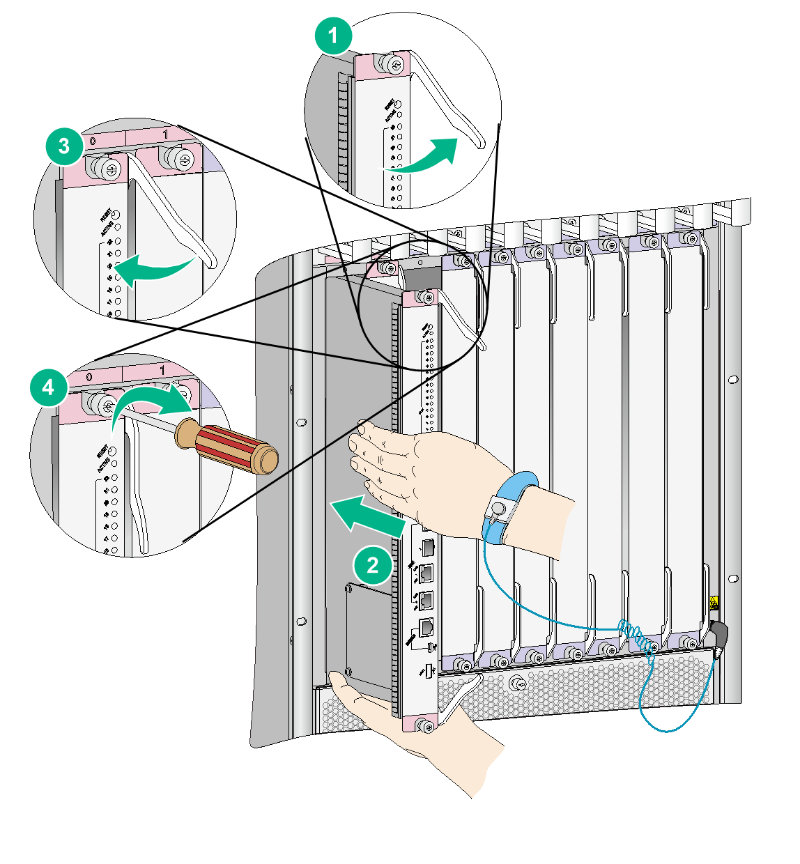
The installation procedure is similar for the cards. The following procedure installs a card in a vertical slot.
To install a card:
1. Wear an ESD wrist strap, and make sure it makes good skin contact and is reliably grounded. For more information, see "Attaching an ESD wrist strap."
2. Remove the filler panel (if any) from the slot. Keep the filler panel for future use.
3. Fully open the two ejector levers on the card.
4. Hold the card by the front panel with one hand and support the card bottom with the other. Slide the card steadily into the slot along the guide rails until you cannot push the card further. Do not touch the components on the card.
5. Fully close the ejector levers until the card come in close contact with the backplane.
6. Fasten the captive screws on the card.
7. When the switch is powered on, verify the running status of the card.
You can verify the running status of a card by referring to the card status LED (SLOT) on the MPU of the switch. If the RUN LED flashes, the card in the slot operates correctly. For more information about card status LED (SLOT), see "Appendix C LEDs."
|
|
NOTE: Some card slots are shipped with no filler panels installed. The preceding figure is for illustration only. |
Installing a power module
|
|
CAUTION: · Provide a circuit breaker for each power module and make sure the circuit breaker is off before installation. · Do not install power modules of different models on the same switch. · When moving the power module, support the bottom of the power module, instead of holding its handle to avoid damaging the power module. · To ensure good ventilation, install a filler panel over an empty slot. |
The switch series uses N + 1 or N + N power redundancy and supports AC or DC power input.
The power module slots are vertical on the switch.
Strictly follow the order shown in Figure 3-3 to avoid security hazards.
Figure 3-3 Power module installation flow
![]()
Installing a power module
An AC power module and a DC power module are installed in the same way. This section uses an AC power module as an example. For information about AC and DC power modules, see H3C AC1200 Power Module User Manual, H3C AC2500 Power Module User Manual and H3C DC2400 Power Module User Manual.
Some power module slots are shipped with no filler panel installed. The figures in this section are for illustration only.
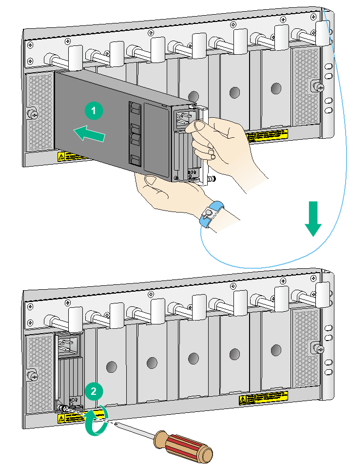
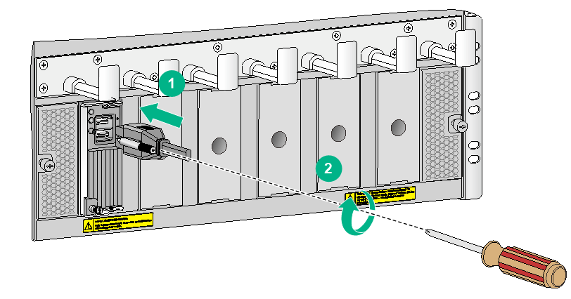
To install the power module:
1. Wear an ESD wrist strap and make sure it makes good skin contact and is reliably grounded. For more information, see "Attaching an ESD wrist strap."
2. Locate the target power module slot. Hold the two holes in the filler panel and pull the filler panel gently out of the slot along the guide rails.
3. Unpack the power module.
4. Grasping the handle of the module with one hand and supporting the module bottom with the other, push the power module along the guide rails into the slot until it has firm contact with the slot.
5. Press the handle inward until the handle seats into the slot.
6. Use a Phillips screwdriver to fasten the captive screw on the handle to attach the power module.
Figure 3-4 Installing a power module
Connecting an AC power cord
|
|
CAUTION: Before connecting an AC power cord, make sure the AC power source circuit breaker is switched off. |
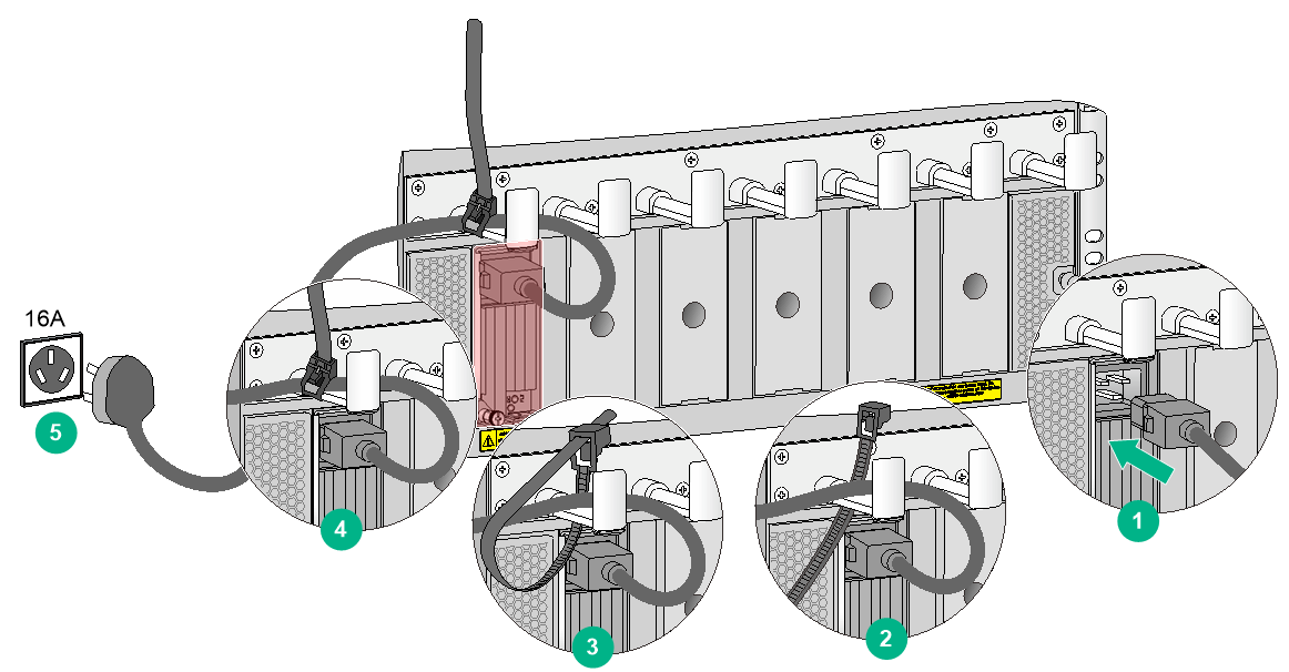
To connect an AC power cord:
1. Connect the female connector of the power cord to the power receptacle on the power module.
2. As shown in Figure 3-5, use a removable cable tie to secure the power cord to the power cord management bracket.
The power cord management bracket on an S10516X switch has a cutout in each hook. You can also feed the removable cable tie through the cutout to secure the power cord.
3. Connect the other end of the power cord to an AC power source and switch on the circuit breaker.
4. Verify the power module input status LED.
If the LED is on, the power cord is correctly connected. For description of power module status LEDs, see "Appendix C LEDs."
Figure 3-5 Connecting an AC power cord
Connecting a DC power cord
|
|
WARNING! · Make sure each DC power cord has a separate circuit breaker. · Before you connect a DC power cord, make sure the DC power source circuit breaker is switched off. |
To connect a DC power cord:
1. Plug the power cord into the power receptacle on the power module.
2. Fasten the screw to secure the power cord.
Figure 3-6 Connecting a DC power cord
3. (Optional.) Use a cable tie to secure the power cord to the power cord management bracket. For more information, see Figure 3-5.
The power cord management bracket on an S10516X switch has a cutout in each hook. You can also feed the removable cable tie through the cutout to secure the power cord.
4. Connect the DC wire marked –48V to the negative terminal (–48V) of the power source and the DC wire marked RTN to the positive terminal (RTN).
Installing fan trays
|
|
CAUTION: To install fan trays in slots FAN 10 to FAN 14 on an S10516X switch, orient the fan tray with the yellow warning sign above the handle. To install fan trays in other slots on the switch, orient the fan tray with the yellow warning sign below the handle. |
The S10508X-V switch provides horizontal fan tray slots. The S10506X, S10508X, and S10510X switches provide vertical fan tray slots. These switches come with a fan tray installed in slot FAN0. You can install a fan tray in slot FAN1 as required.
The S10516X switch provides vertical fan tray slots. The switch comes with a fan tray installed in each fan tray slot.
The fan tray installation procedure is similar for horizontal and vertical slots. The following procedure uses the S10508X-V switch as an example.
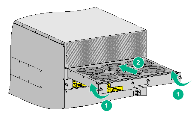
To install a fan tray:
1. Wear an ESD wrist strap and make sure it makes good skin contact and is reliably grounded. For more information, see "Attaching an ESD wrist strap."
2. Unpack the fan tray.
3. Holding the fan tray handle with one hand and supporting the fan tray bottom with the other, align the fan tray with the target slot.
4. Push the fan tray into the slot along the guide rails. Make sure the fan tray is fully seated in the slot.
5. Use a screwdriver to fasten the captive screws on the fan tray.
Figure 3-7 Installing a fan tray
(Optional) Installing transceiver modules and network cables
|
|
WARNING! Disconnected optical fibers or transceiver modules might emit invisible laser light. Do not stare into beams or view directly with optical instruments when the switch is operating. |
Installing an SFP+/SFP/SFP28/QSFP+/QSFP28 transceiver module
|
|
CAUTION: To avoid transceiver module or port damage, read this guide carefully before installing a transceiver module. |
|
|
CAUTION: · Be careful not to touch the golden plating on a transceiver module during the installation process. · Before installing a transceiver module, remove the optical fibers, if any, from it. · Make sure the transceiver module is aligned correctly with the target port before pushing it into the port. · Do not remove the dust plugs from a transceiver module until you are ready to install optical fibers for it. |
Two types of QSFP+ transceiver modules are available. One type uses a metal pull latch and the other type uses a plastic pull latch. The installation procedure is the same for the two types of QSFP+ transceiver modules.
The installation procedure is similar for the SFP+, SFP, SFP28, QSFP+, and QSFP28 transceiver modules. The following procedure installs an SFP+ transceiver module.
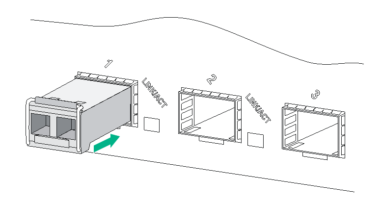
To install an SFP+ transceiver module:
1. Wear an ESD wrist strap and make sure it makes good skin contact and is reliably grounded. For more information, see "Attaching an ESD wrist strap."
2. Remove the dust plug from the target fiber port.
3. Unpack the SFP+ transceiver module. It comes with the bail latch catching the knob on the top of the transceiver module.
4. Grasp the transceiver module between your thumb and index finger. Align it with the fiber port and push it gently into the port until it snaps into place.
Transceiver modules and fiber ports have disorientation rejection designs. If you cannot insert a transceiver module easily into a port, the orientation might be wrong. Remove and reorient the transceiver module.
In case of limited space, you can gently push against the front face of the transceiver module instead of the two sides.
5. Connect optical fibers to the transceiver module. For the connection procedure, see "Connecting your switch to the network through optical fibers."
Figure 3-8 Installing an SFP+ transceiver module
Connecting a network cable
|
|
CAUTION: When you connect a network cable, follow these restrictions and guidelines: · Make sure the two modular ends of a network cable are compatible with the ports into which they will be inserted. · Do not touch the golden plating on the two modular ends of the network cable. · To avoid network cable damage and signal loss, do not strain or tangle a network cable. · Before inserting a modular end of a network cable into a port, make sure the module aligns with the port correctly. · The bend radius of a DAC cable and AOC cable must be a minimum of 15 and 20 times the cable diameter, respectively. |
To connect ports over a short distance, use network cables as follows:
· SFP+ DAC cable—Connects two SFP+ ports over a short distance.
· QSFP+ DAC or QSFP+ AOC cable—Connects two QSFP+ ports over a short distance.
· QSFP+ to SFP+ DAC cable—Connects one QSFP+ port to four SFP+ ports over a short distance.
The network cables are hot swappable. The connection procedure is similar for these cables. The following procedure connects an SFP+ DAC cable.
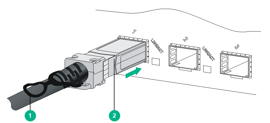
To connect an SFP+ DAC cable:
1. Wear an ESD wrist strap and make sure it makes good skin contact and is reliably grounded. For more information, see "Attaching an ESD wrist strap."
2. Remove the dust plug from the target fiber port.
3. Unpack the cable.
4. As shown in Figure 3-9, align the module end of the cable with the fiber port and push it gently into the port until you feel it snaps into place.
Transceiver modules and fiber ports have disorientation rejection structures. If you cannot insert a transceiver module easily into a port, remove and reorient the transceiver module.
Figure 3-9 Connecting an SFP+ DAC cable
|
(1) Pull latch |
(2) Connector |
