- Table of Contents
- Related Documents
-
| Title | Size | Download |
|---|---|---|
| 01-Internet Access Configuration Examples | 530.61 KB |
Contents
Example: Accessing the Internet through a physical interface
Example: Configuring dial-up Internet access by using a mobile communication modem
Introduction
The following information provides examples of configuring routers to access the Internet through a physical interface and a mobile communication modem.
Prerequisites
This document is not restricted to specific software or hardware versions. Procedures and information in the examples might be slightly different depending on the software or hardware version of the device.
The configuration examples were created and verified in a lab environment, and all the devices were started with the factory default configuration. When you are working on a live network, make sure you understand the potential impact of every command on your network.
The following information is provided based on the assumption that you have basic knowledge of PPPoE, DHCP, and mobile communication modems.
Software versions used
This configuration example was created and verified on MSR3610-X1 R6749P21.
Example: Accessing the Internet through a physical interface
Network configuration
As shown in Figure 1, the WAN interface on the router connects to the WAN. You can access the Internet through the WAN interface.

Procedures
# In this example, select the single-WAN scenario. The configuration procedures are as follows:
1. Make sure the PC and the router can communicate with each other. (Details not shown.)
2. Log in to the router management Web page. Navigate to Network > WAN Settings.
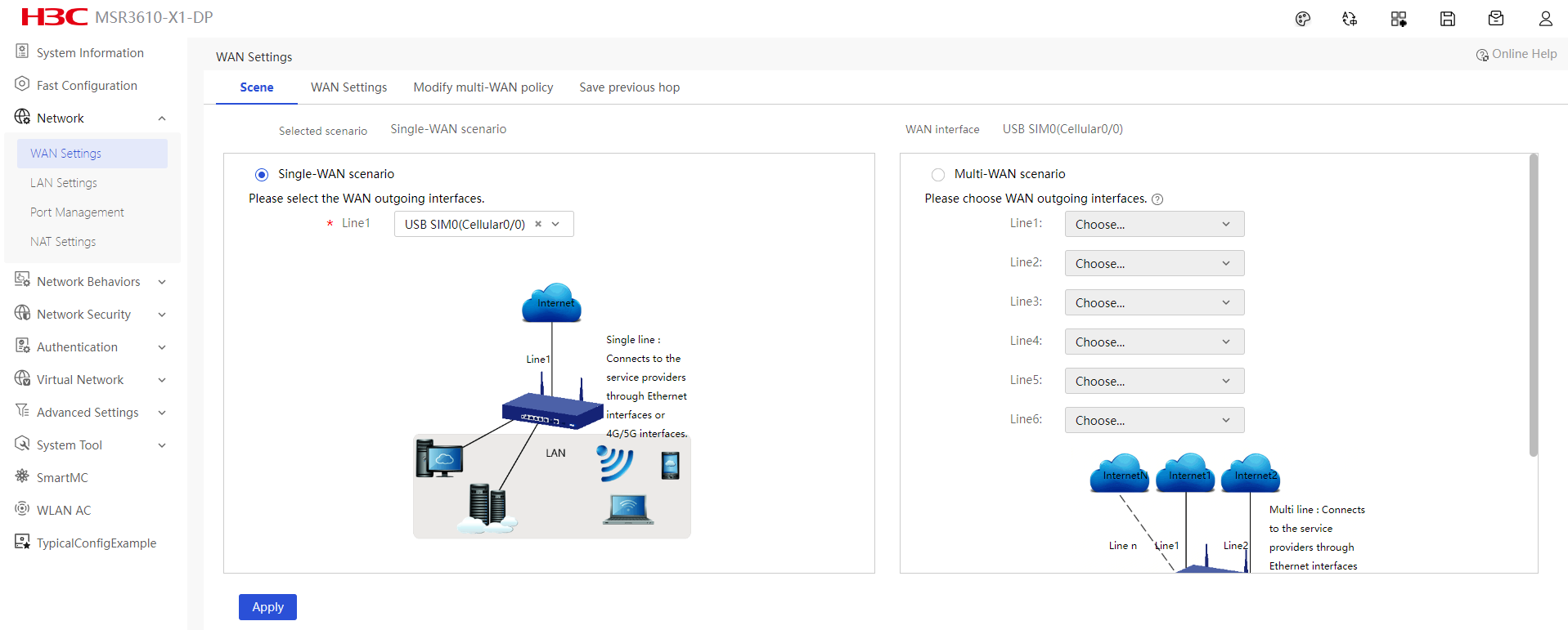
3. Click the Scene tab and select Single-WAN scenario.
4. In the single-WAN scenario, select the interface for accessing the WAN in the Line1 field. In this example, select WAN1 (GE1).
Figure 2 Selecting WAN access scenario

5. On the link list, click the Edit icon in the Actions column for line 1. The page for editing the WAN configuration opens.
6. In the Connection mode field, select a connection mode as needed.
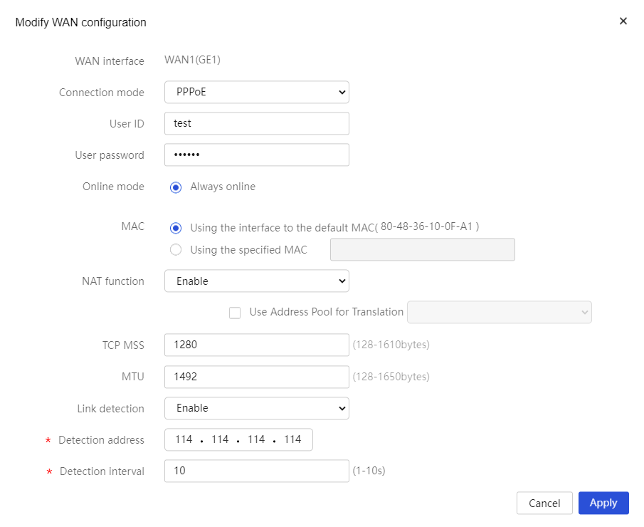
¡ If you select the PPPoE connection mode, perform the following tasks:
- In the User ID field, enter the PPPoE access username provided by the service provider. In this example, enter test.
- In the User Password field, enter the PPPoE access password provided by the service provider. In this example, enter 123456.
- Select Always Online for the Online Mode field.
- In the MAC Address field, select Using the interface to the default MAC.
- In the NAT field, enable NAT.
- In the TCP MSS and MTU fields, configure the maximum segment size (MSS) of TCP packets and the MTU for the interface. In this example, use the default settings.
- In the Link detection field, enable this feature and enter 114.114.114.114 as the IP address for link detection and 10 as the interval for link detection.
Figure 3 Selecting the PPPoE connection mode
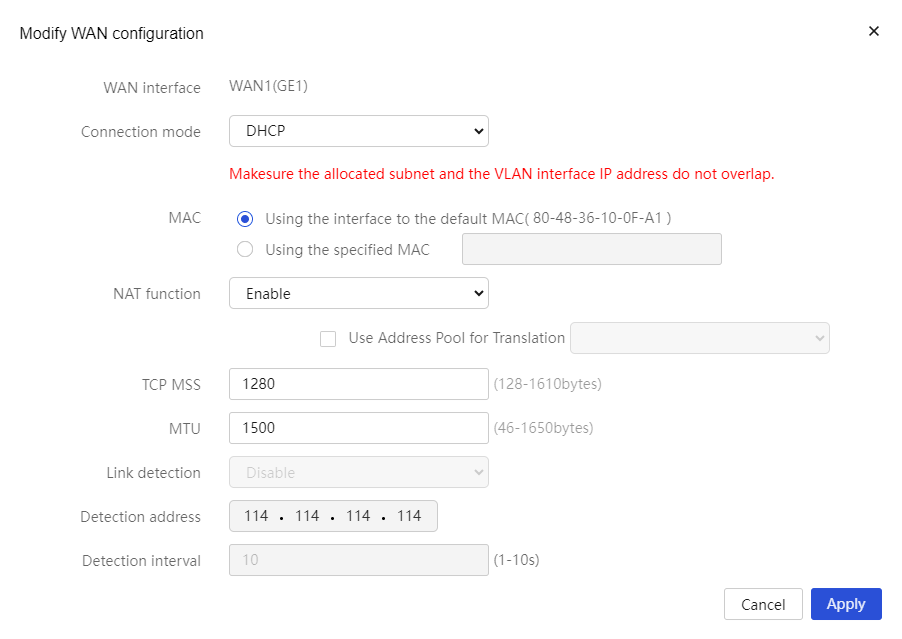
¡ If you select the DHCP connection mode, the DHCP server automatically assigns the public IP addresses for accessing the WAN.
- In the MAC Address field, select Using the interface to the default MAC.
- In the NAT field, enable NAT.
- In the TCP MSS and MTU fields, configure the maximum segment size (MSS) of TCP packets and the MTU for the interface. In this example, use the default settings.
Figure 4 Selecting the DHCP connection mode
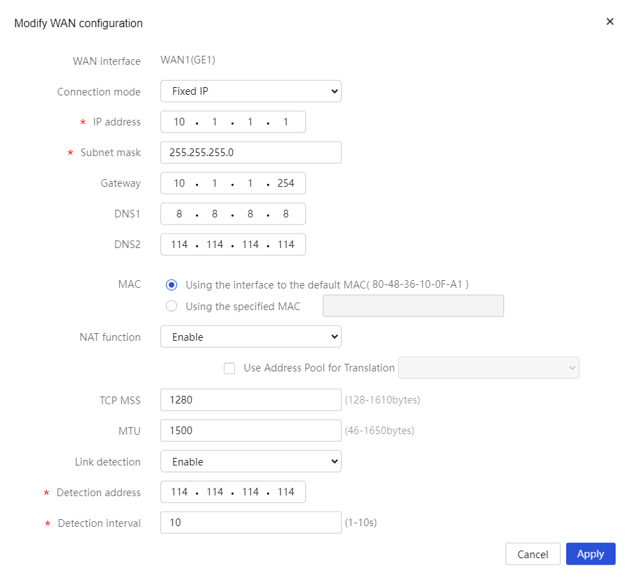
¡ If you select the fixed IP connection mode, perform the following tasks:
- In the IP address field, enter the fixed IP address for accessing the WAN. In this example, enter 10.1.1.1.
- In the Subnet Mask field, enter the mask or mask length for the IP address, for example, 255.255.255.0 or 24.
- In the Gateway address field, enter the gateway address for accessing the WAN. In this example, enter 10.1.1.254.
- In the DNS1 and DNS2 fields, enter the IP addresses of DNS servers for accessing the WAN. In this example, enter 8.8.8.8 and 114.114.114.114.
- In the MAC Address field, select Using the interface to the default MAC.
- In the NAT field, enable NAT.
- In the TCP MSS and MTU fields, configure the maximum segment size (MSS) of TCP packets and the MTU for the interface. In this example, use the default settings.
- In the Link detection field, enable this feature and enter 114.114.114.114 as the IP address for link detection and 10 as the interval for link detection.
Figure 5 Selecting the fixed IP connection mode
7. Click Apply to complete editing the WAN configuration.
Example: Configuring dial-up Internet access by using a mobile communication modem
Network configuration
As shown in Figure 6, the router is installed with a USB 3G/4G modem or SIC-3G/4G/5G interface module and accesses the 3G/4G/5G network via DDR. LAN users can access the Internet through a 3G/4G/5G link.
The configuration for dial-up Internet access by using a 4G modem is the same as that by using a 3G or 5G modem. This example describes how to configure a 4G modem for dial-up Internet access.

Procedures
|
|
NOTE: Select the WAN output interface based on the type of the modem and the slot number of the SIM card. If you use a USB 4G modem for dial-up Internet access, select USB SIM0 (Cellular0/0). If you use a SIC-4G interface module for dial-up Internet access and the SIM card is on slot 1, select SIM0(Cellular1/0). If you use a SIC-4G interface module for dial-up Internet access and the SIM card is on slot 2, select SIM1(Cellular1/1). |
# In this example, select the single-WAN scenario and use a USB 4G modem for Internet access with China Mobile as the service provider. The configuration procedures are as follows:
1. Make sure the PC and the router can communicate with each other. (Details not shown.)
2. Log in to the Router's Web page. Navigate to Network > WAN Settings.
3. Click the Scene tab and select Single-WAN scenario.
4. In the Line1 field, select USB SIM0(Cellular0/0).
5. Click Apply to complete the configuration.
Figure 7 Selecting WAN access scenario
6. Click the WAN Settings tab.
7. Click the Edit icon in the Actions column for USB SIM0(Cellular0/0).
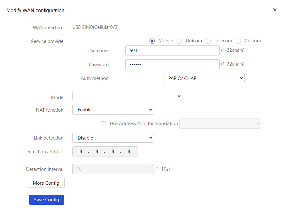
8. In the Service provider field, select Mobile, and then configure the following parameters:
¡ In the Username field, enter the username provided by the service provider. In this example, enter test.
¡ In the Password field, enter the password provided by the service provider. In this example, enter test123.
¡ From the Auth method list, select an authentication method. Options include PAP or CHAP (the device and user login terminal automatically negotiate to select PAP or CHAP), PAP, and CHAP. PAP is applicable in an environment with low security requirements. CHAP is securer than PAP. The selected authentication method takes effect only after you have set the username and password. In this example, select PAP or CHAP.
9. In the Network standard field, select the network standard of China Mobile. Use the default settings for the other parameters.
10. Click Save Config to complete editing the WAN configuration.
Figure 8 Configuring USB SIM0 (Cellular0/0)
Verifying the configuration
After completing the above configuration, verify that the PC can access the Internet.
