- Table of Contents
- Related Documents
-
| Title | Size | Download |
|---|---|---|
| 01-L2TP VPN Configuration Examples | 778.25 KB |
Introduction
This document provides examples for configuring L2TP VPNs on routers.
Prerequisites
This document is not restricted to specific software or hardware versions. Procedures and information in the examples might be slightly different depending on the software or hardware version of the device.
The configuration examples were created and verified in a lab environment, and all the devices were started with the factory default configuration. When you are working on a live network, make sure you understand the potential impact of every command on your network.
This document assumes that you have basic knowledge of L2TP VPN.
Software version used
This configuration example was created and verified on version 6749P21 of MSR3610-X1.
Example: Configuring L2TP VPNs
Network configuration
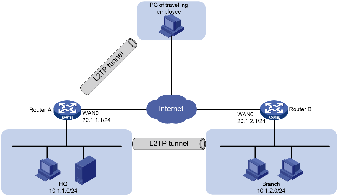
As shown in Figure 1, the enterprise needs to create L2TP tunnels to allow traveling employees and employees in branches to access servers on the internal network deployed in the HQ.
Analysis
1. Configure Router A for the HQ to access the Internet, and enable the L2TP server on Router A.
2. Configure Router B for a branch to access the Internet, and enable the L2TP client on Router B.
3. Configure the L2TP client on the PCs of traveling employees.
Procedures
Configuring Router A
Connecting interface WAN1 to the Internet
|
|
NOTE: In this example, select the single-WAN scenario for Router A, and set the connection mode of the selected WAN interface to fixed IP. |
1. From the navigation pane, select Network > External Networks.
2. On the Scenario Definitions tab, select the Single-WAN scenario, select WAN1(GE1) for the Line 1 field, and click Apply.
3. Click the WAN Settings tab.
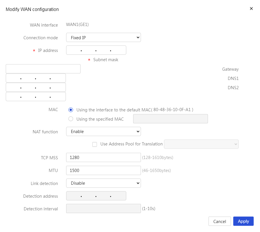
4. Click the Edit icon for interface WAN1. On the page that opens, perform the following tasks:
a. Select Fixed IP from the Connection mode list.
b. Enter 20.1.1.1 in the IP address field.
c. Enter 255.255.255.0 in the Subnet mask field.
d. Enter 20.1.1.254 in the Gateway field.
e. Enter 114.114.114.114 in the DNS1 field.
f. Enter 223.5.5.5 in the DNS2 field.
g. Use the default settings for the other parameters.
5. Click Apply to save the configuration.
Figure 2 Configuring interface WAN1 connecting to the Internet
Enabling and configuring the L2TP server
|
|
NOTE: In this example, you must configure two L2TP groups (tunnels) named LNS1 and LNS2, which provide connections for PCs of traveling employees and routers in branches separately. |
1. From the navigation pane, select Virtual Network > L2TP Server. Select Enable for the L2TP Server field, and click Apply.
2. Configure LNS1 (for PCs of traveling employees):
a. On the L2TP Config tab, click Add.
b. On the Create L2TP Group page that opens, do not select the Tunnel peer name option, and you do not need to configure a peer tunnel name.
If you select this option, you must enter the name of the PC of a traveling employee.
c. Enter LNS1 in the Local tunnel name field.
d. Select Disable for the Tunnel authentication field.
When a PC acts as an L2TP client, as a best practice, do not enable tunnel authentication.
e. Select CHAP from the PPP authentication method list.
f. Enter a VT interface address as needed (for example, 172.16.10.1) in the VT interface address field.
Make sure it is not an internal network IP address.
g. Enter a VT interface address mask (for example, 255.255.255.0) in the VT interface Mask field.
h. Enter a user address pool (for example, 172.16.10.2-172.16.10.5) in the User address pool field.
i. Use the default settings for the other parameters.
j. Click Apply.
Figure 3 Configuring LNS1

3. Configure LNS2 (for routers in branches):
a. On the L2TP Config tab, click Add.
b. On the Create L2TP Group page that opens, enter a peer tunnel name (for example, LAC) in the Tunnel peer name field.
c. Enter LNS2 in the Local tunnel name field.
d. Select Enable for the Tunnel authentication field, and enter abc123 in the Tunnel authentication password field.
e. Select CHAP from the PPP authentication method list.
f. Enter a VT interface address as needed (for example, 172.16.20.1) in the VT interface address field.
Make sure it is not on the same subnet as an internal network IP address.
g. Enter a VT interface address mask (for example, 255.255.255.0) in the VT interface Mask field.
h. Enter a user address pool (for example, 172.16.20.2-172.16.20.5) in User address pool field.
i. Use the default settings for the other parameters.
j. Click Apply.
Figure 4 Configuring LNS2
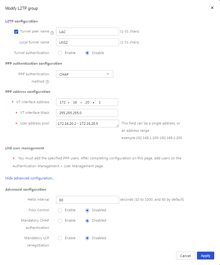
Figure 5 Configuring L2TP groups

Adding L2TP users
|
|
NOTE: L2TP user settings mainly include the username and password for an L2TP client to dial up. |
1. Configure the username and password for the branch router acting as a client:
a. From the navigation pane, select Authentication > User Management.
b. Click the User Settings tab.
c. Click Add.
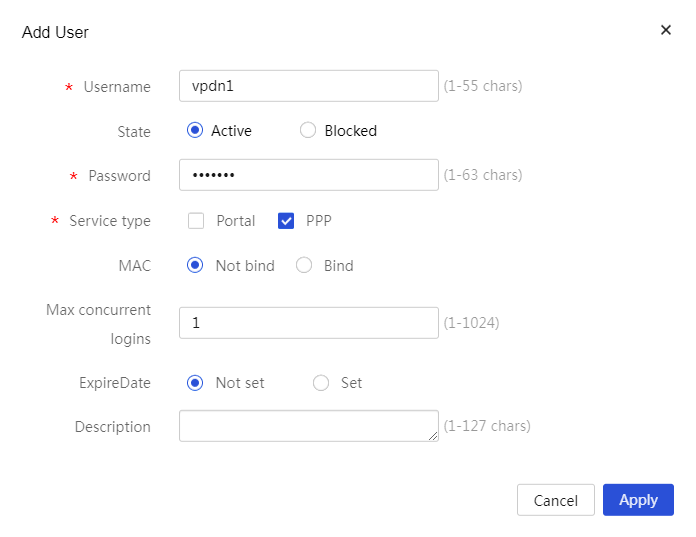
d. On the Add User page that opens, enter a username (for example, vpdn1) in the Account field.
e. Select Active for the State field.
f. Enter a password (for example, user123) in the Password field.
g. Select PPP for the Service type field.
h. Select Not bind for the MAC field.
i. Enter the maximum number of concurrent L2TP client connections supported by the account (for example, 1) in the Max concurrent logins field.
j. Select Not set for the ExpireDate field.
If you select Set, you must select the validity period of the account from the date selector.
k. Click Apply.
Figure 6 Adding an L2TP user
2. Add the username and password for the PCs of traveling employees.
Add username vpdnuser and password user1234 in the same way.
Configuring Router B
Connecting interface WAN1 to the Internet
|
|
NOTE: In this example, select the single-WAN scenario for Router B, and set the connection mode of the selected WAN interface to fixed IP. |
1. From the navigation pane, select Network > External Networks.
2. On the Scenario Definitions tab, select the Single-WAN scenario, select WAN1(GE1) for the Line1 field, and click Apply.
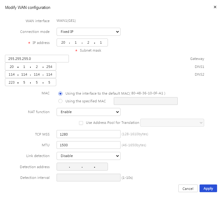
3. Click the WAN Settings tab. Then, click the Edit icon for interface WAN1. On the page that opens, perform the following tasks:
a. Select Fixed IP from the Connection mode list.
b. Enter 20.1.2.1 in the IP address field.
c. Enter 255.255.255.0 in the Subnet mask field.
d. Enter 20.1.2.254 in the Gateway field.
e. Enter 114.114.114.114 in the DNS1 field.
f. Enter 223.5.5.5 in the DNS2 field.
g. Use the default settings for the other parameters.
4. Click Apply to save the configuration.
Figure 7 Configuring interface WAN1 connecting to the Internet
Enabling and configuring the L2TP client
|
|
NOTE: When configuring an L2TP client, make sure the L2TP client information is the same as that on the L2TP server. |
1. From the navigation pane, Select Virtual Network > L2TP Client.
2. Click the L2TP Config tab.
3. Select Enable for the L2TP Client field and click Apply.
4. Click Add. On the Create L2TP Group page that opens, perform the following tasks:
a. Enter LAC in the Local tunnel name field.
b. Select Dynamic for the Address assignment method field.
c. Select Enable for the Tunnel authentication field. Then, enter password abc123, which is set for LNS2, in the Tunnel authentication password field.
d. Select CHAP from the PPP authentication method list. Then, enter vpdn1 in the Username field and user123 in the Password field.
e. Enter 20.1.1.1 (IP address of interface WAN1 in the HQ) in the L2TP server address field.
f. Use the default settings for the other parameters.
g. Click Apply.
Figure 8 Configuring the L2TP client

Configuring static routes
|
|
NOTE: · When the router acts as an L2TP client, you must add a static route destined to the subnet of the L2TP server (10.1.1.0/24). · When the router acts as an L2TP client, you must add a static route destined to 20.1.1.0/24 in order to access the L2TP server. |
1. From the navigation pane, select Advanced Settings > Static Routing.
2. Click Add. On the New IPv4 Static Route page that opens, perform the following tasks:
a. Enter 10.1.1.0 in the Destination IP address field.
b. Enter 24 in the Mask length field.
c. Select GE1 (the L2TP tunnel interface) for the Next hop field.
d. Use the default settings for the other parameters. Click Apply.
Figure 9 Configuring static routes

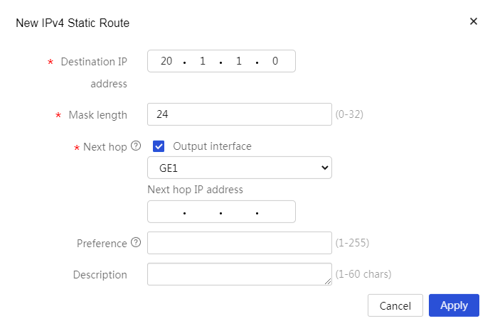
3. (Optional.) From the navigation pane, select Advanced Settings > Static Routing. Click Add. On the New IPv4 Static Route page that opens, perform the following tasks:
a. Enter 20.1.1.0 in the Destination IP address field.
b. Enter 24 in the Mask length field.
c. Select GE1 (the L2TP tunnel interface) for the Next hop field.
d. Use the default settings for the other parameters. Click Apply.
Figure 10 Configuring static routes
Configuring PCs of traveling employees
|
|
NOTE: On the PC of a traveling employee, configure the L2TP client. In this example, the PC is installed with Windows 7. |
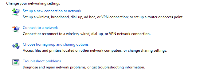
1. Log in to the PC of the traveling employee. Click Open Network and Sharing Center.
2. Click Set up a new connection or network.
Figure 11 Setting up a new connection or network
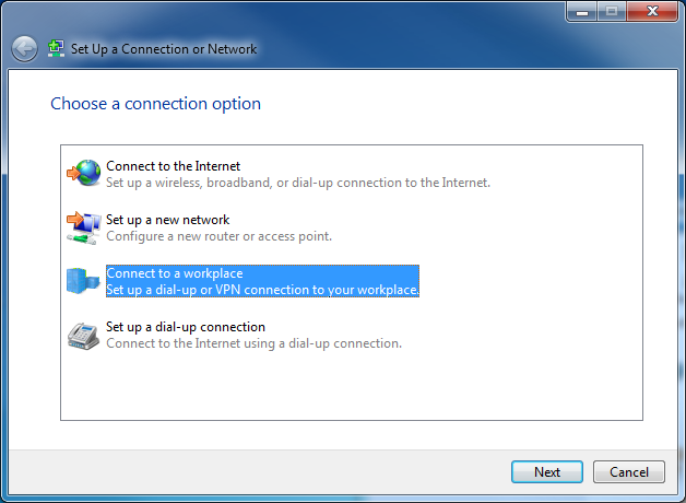
3. In the Set up a Connection or Network window, select Connect to a workplace, and then click Next.
Figure 12 Connecting to a workplace
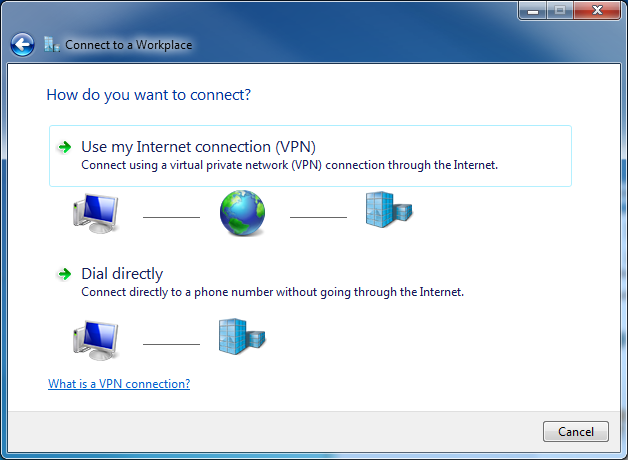
4. Select Use my Internet connection (VPN), and then select I’ll set up an Internet connection later. Then, you can configure the Internet address for the connection.
Figure 13 Using my Internet connection (VPN)

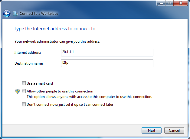
5. In the Internet address field, enter the IP address of interface WAN1 of the L2TP server to be connected, 20.1.1.1 in this example. In the Destination name field, enter the name of the L2TP client connection, l2tp in this example. Then, click Next.
Figure 14 Entering the Internet address to connect to
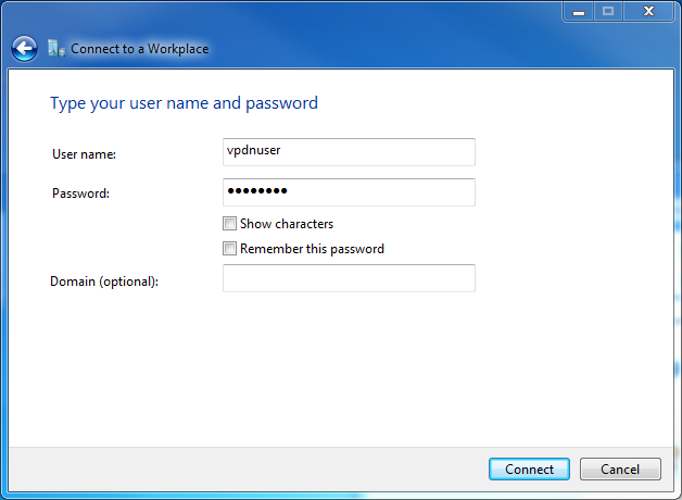
6. In the User name and Password fields, enter the username and password set on the L2TP server, vpdnuser and user1234 in this example. Click Create.
Figure 15 Entering the username and password
7. Click the Network ![]() icon in
the lower right corner of the desktop. Right-click the
L2TP client name (for example, l2tp), and select Properties.
icon in
the lower right corner of the desktop. Right-click the
L2TP client name (for example, l2tp), and select Properties.
Figure 16 L2TP client properties

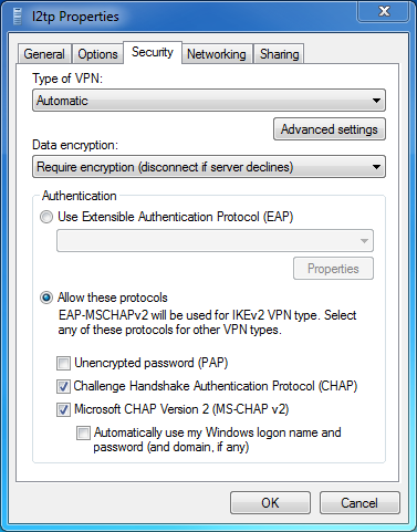
8. In the Properties dialog box that opens, click the Security tab. On this tab, select Layer 2 Tunneling Protocol with IPsec (L2TP/IPsec) from the Type of VPN list, select Optional encryption (connect even if no encryption) from the Data encryption list, and then click OK.
Figure 17 Security properties
9. Open the dialup terminal for L2TP, and enter username vpdnuser and password user1234 in the Connect dialog box that opens. Then, click Connect.
Figure 18 Connecting L2TP

Verifying the configuration
1. Verify that both traveling employees and employees in branches can access servers in the HQ.
2. Log in to the Web interface of Router A for the HQ. From the navigation pane, select Virtual Network > L2TP Server. Click the Tunnel Info tab. Verify that you can view the corresponding L2TP tunnel information on this tab.