- Table of Contents
-
- 04-Layer 3—IP Services Configuration Guide
- 00-Preface
- 01-ARP configuration
- 02-IP addressing configuration
- 03-DHCP configuration
- 04-DNS configuration
- 05-IP forwarding basics configuration
- 06-Fast forwarding configuration
- 07-Adjacency table configuration
- 08-IRDP configuration
- 09-IP performance optimization configuration
- 10-UDP helper configuration
- 11-IPv6 basics configuration
- 12-DHCPv6 configuration
- 13-IPv6 fast forwarding configuration
- 14-Tunneling configuration
- 15-GRE configuration
- 16-HTTP redirect configuration
- Related Documents
-
| Title | Size | Download |
|---|---|---|
| 14-Tunneling configuration | 231.67 KB |
Contents
Supported tunneling technologies
Restrictions and guidelines: Tunnel interface configuration
Restrictions and guidelines: Tunnel interface configuration
Prerequisites for tunnel configuration
Configuring a tunnel interface
About tunnel interface configuration
Tunnel interface configuration tasks at a glance
Configuring parameters for tunneled packets
Specifying the tunnel destination VPN instance
Restoring the default settings of the tunnel interface
Adding TUNNEL to the PHY_UPDOWN log mnemonic for tunnel interfaces
Assigning a VXLAN tunnel interface to a VXLAN tunnel group
Enabling SNMP notifications for the tunneling module
Display and maintenance commands for tunnel interface configuration
Troubleshooting tunnel interface configuration
About IPv6 over IPv4 tunneling
IPv6 over IPv4 tunneling tasks at a glance
Configuring an IPv6 over IPv4 tunnel
Example: Configuring an IPv6 over IPv4 tunnel
Enabling dropping IPv6 packets that use IPv4-compatible IPv6 addresses
About IPv4 over IPv4 tunneling
Restrictions and guidelines: IPv4 over IPv4 tunnel configuration
Configuring an IPv4 over IPv4 tunnel
Testing the reachability of a path
Configuring a source-destination address pair for IPv4-in-IPv4 packet decapsulation
Constructing multi-layer encapsulated IPv4-in-IPv4 packets on a host
Testing the reachability of a path
IPv4 over IPv4 tunnel configuration examples
Example: Configuring an IPv4 over IPv4 tunnel
Configuring tunneling
This chapter describes tunnel interface configuration. For information about tunnel modes, see the subsequent chapters.
About tunneling
Tunneling encapsulates the packets of a network protocol within the packets of a second network protocol and transfers them over a virtual point-to-point connection. The virtual connection is called a tunnel. Packets are encapsulated at the tunnel source and de-encapsulated at the tunnel destination.
Supported tunneling technologies
Tunneling supports the following technologies:
· GRE tunneling. For more information, see "Configuring GRE."
· MPLS TE tunneling. For more information, see MPLS Configuration Guide.
· VXLAN tunneling and VXLAN-DCI tunneling. For more information, see VXLAN Configuration Guide.
· IPv6 over IPv4 tunneling and IPv4 over IPv4 tunneling.
Restrictions and guidelines: Tunnel interface configuration
The device does not support tunneling when it is operating in enhanced Layer 2 mode (set by using the system-working-mode bridgee command).
Restrictions and guidelines: Tunnel interface configuration
Prerequisites for tunnel configuration
The device cannot directly route a tunneled packet based on its destination address. The packet is sent to a tunnel-type service loopback group, which then delivers the packet to the forwarding module for Layer 3 forwarding. For the tunnel interface to forward and receive packets, you must configure a tunnel-type service loopback group on the device. For information about service loopback group, see Layer 2—LAN Switching Configuration Guide.
Configuring a tunnel interface
About tunnel interface configuration
Configure a tunnel interface (Layer 3 virtual interface) at both ends of a tunnel. The devices use the tunnel interface to identify, process, and send packets for the tunnel.
Tunnel interface configuration tasks at a glance
To configure a tunnel interface, perform the following tasks:
1. Creating a tunnel interface
2. (Optional.) Configuring parameters for tunneled packets
3. (Optional.) Specifying the tunnel destination VPN instance
4. (Optional.) Restoring the default settings of the tunnel interface
5. (Optional.) Adding TUNNEL to the PHY_UPDOWN log mnemonic for tunnel interfaces
6. (Optional.) Assigning a VXLAN tunnel interface to a VXLAN tunnel group
7. (Optional.) Enabling SNMP notifications for the tunneling module
Creating a tunnel interface
1. Enter system view.
system-view
2. Create a tunnel interface, specify the tunnel mode, and enter tunnel interface view.
interface tunnel number mode { gre | ipv4-ipv4 | ipv6-ipv4 | mpls-te | vxlan | vxlan-dci }
For packet tunneling to succeed, the two ends of a tunnel must use the same tunnel mode.
3. Configure a source address or source interface for the tunnel interface.
source { ipv4-address | interface-type interface-number }
By default, no source address or source interface is configured for the tunnel interface.
If you specify a source address, it is used as the source address of tunneled packets.
If you specify a source interface, the primary IP address of this interface is used as the source IP address of tunneled packets.
4. Configure a destination address for the tunnel interface.
destination ipv4-address
By default, no destination address is configured for the tunnel interface.
The tunnel destination address must be the IP address of the receiving interface on the tunnel peer. It is used as the destination IP address of tunneled packets.
5. (Optional.) Configure a description for the interface.
description text
By default, the description for a tunnel interface is Tunnel number Interface.
6. (Optional.) Set the MTU of the tunnel interface.
mtu size
The default settings are as follows:
¡ If the tunnel interface has never been up, the MTU is 64000 bytes.
¡ If the tunnel interface is up, its MTU is identical to the outgoing interface's MTU minus the length of the tunnel headers. The outgoing interface is automatically obtained through routing table lookup based on the tunnel destination address.
7. (Optional.) Set the expected bandwidth for the tunnel interface.
bandwidth bandwidth-value
The default expected bandwidth (in kbps) is the interface maximum rate divided by 1000.
The expected bandwidth is an informational parameter used only by higher-layer protocols for calculation. You cannot adjust the actual bandwidth of an interface by using this command.
8. Bring up the tunnel interface.
undo shutdown
By default, a tunnel interface is administratively down.
Configuring parameters for tunneled packets
1. Enter system view.
system-view
2. Enter tunnel interface view.
interface tunnel number
3. Set the ToS for tunneled packets.
tunnel tos { copy-inner-tos | tos-value }
The default settings are as follows:
¡ For VXLAN tunneled packets, the ToS is 0.
¡ For non-VXLAN tunneled packets, the ToS is the same as the ToS of the original packets.
The copy-inner-tos keyword is supported only by VXLAN tunnels.
4. Set the TTL for tunneled packets.
tunnel ttl ttl-value
The default TTL for tunneled packets is 255.
Specifying the tunnel destination VPN instance
Restrictions and guidelines
For a tunnel interface to come up, the tunnel source and destination must belong to the same VPN instance. To specify a VPN instance for the tunnel source, use the ip binding vpn-instance command on the tunnel source interface. For more information about this command, see MPLS Command Reference.
Procedure
1. Enter system view.
system-view
2. Enter tunnel interface view.
interface tunnel number
3. Specify the VPN instance to which the tunnel destination belongs.
tunnel vpn-instance vpn-instance-name
By default, the tunnel destination belongs to the public network.
Restoring the default settings of the tunnel interface
Restrictions and guidelines
|
|
CAUTION: This operation might interrupt ongoing network services. Make sure you are fully aware of the impact of this operation when you perform it on a live network. |
This operation might fail to restore the default settings for some commands for reasons such as command dependencies or system restrictions. Use the display this command in interface view to identify these commands. Use their undo forms or follow the command reference to restore their default settings. If your restoration attempt still fails, follow the error message instructions to resolve the problem.
Procedure
1. Enter system view.
system-view
2. Enter tunnel interface view.
interface tunnel number
3. Restore the default settings of the tunnel interface.
default
Adding TUNNEL to the PHY_UPDOWN log mnemonic for tunnel interfaces
About this task
This feature adds the TUNNEL string to the PHY_UPDOWN log mnemonic for tunnel interfaces. Use this feature if you want to identify the interface state change logs for tunnel interfaces by using a regular expression that contains the TUNNEL string.
A tunnel interface state change log without the TUNNEL string in the mnemonic:
%Jan 8 18:45:33:621 2011 Sysname IFNET/3/PHY_UPDOWN: Physical state on the interface Tunnel1 changed to down.
A tunnel interface state change log with the TUNNEL string in the mnemonic:
%Jan 8 18:45:33:621 2011 Sysname IFNET/3/TUNNEL_PHY_UPDOWN: Physical state on the interface Tunnel1 changed to down.
Procedure
1. Enter system view.
system-view
2. Add the TUNNEL string to the PHY_UPDOWN log mnemonic for tunnel interfaces.
tunnel log updown with-tag
By default, the PHY_UPDOWN log mnemonic for tunnel interfaces does not contain the TUNNEL string.
Assigning a VXLAN tunnel interface to a VXLAN tunnel group
About this task
This feature assigns a VXLAN tunnel interface to a VXLAN tunnel group. A VXLAN tunnel group contains one or multiple VXLAN tunnel interfaces on the same device.
Use this feature in conjunction with the traffic redirection feature to replicate and forward traffic on multiple VXLAN tunnels in a VXLAN tunnel group. For more information about traffic redirection, see QoS in ACL and QoS Command Reference.
Restrictions and guidelines
A VXLAN tunnel interface can be assigned only to one VXLAN tunnel group. To assign the VXLAN tunnel interface to another VXLAN tunnel group, first remove the VXLAN tunnel interface from the original group by using the undo group command.
A VXLAN tunnel group can contain a maximum of two VXLAN tunnel interfaces.
Procedure
1. Enter system view.
system-view
2. Enter VXLAN tunnel interface view.
interface tunnel number
3. Assign the VXLAN tunnel interface to a VXLAN tunnel group.
group group-id
By default, a VXLAN tunnel interface is not assigned to any VXLAN tunnel group.
Enabling SNMP notifications for the tunneling module
About this task
After you enable the max-threshold-reached notification, when the number of tunnel interfaces exceeds the warning threshold (80% of the maximum), the device generates SNMP notifications that record the chassis number and slot number of the exceeding tunnel interfaces.
After you enable the vxlan-config-failure notification, when a VXLAN tunnel failed to be deployed, the device generates an SNMP notification that records the interface number of the tunnel.
After you enable the vxlan-decap-failure notification, when a VXLAN packet failed to be decapsulated, the device generates an SNMP notification that records the source IP type, source IP address, destination IP type, and destination IP address of the VXLAN packet.
After you enable the vxlan-tunnel-status notification, the device generates SNMP notifications for VXLAN over IPv4 tunnels when the tunnel status changes.
After you enable the vxlan-ipv6-tunnel-status notification, the device generates SNMP notifications for VXLAN over IPv6 tunnels when the tunnel status changes.
If you do not specify the notification types to be enabled, the device enables SNMP notifications for both VXLAN over IPv4 and VXLAN over IPv6 tunnel status change events.
To output tunnel notifications correctly, you must also configure parameters for sending SNMP notifications. For more information about SNMP configuration, see Network Management and Monitoring Configuration Guide.
Software version and feature compatibility
This feature is supported only in Release 2825 and later.
Procedure
1. Enter system view.
system-view
2. Enable SNMP notifications for the tunneling module.
snmp-agent trap enable tunnel [ max-threshold-reached | vxlan-config-failure | vxlan-decap-failure | vxlan-tunnel-status | vxlan-ipv6-tunnel-status ] *
By default, SNMP notifications for the tunneling module are disabled.
Display and maintenance commands for tunnel interface configuration
Execute display commands in any view and reset commands in user view.
|
Task |
Command |
Remarks |
|
Display information about tunnel interfaces. |
display interface [ tunnel [ number ] ] [ brief [ description | down ] ] |
N/A |
|
Display IPv6 information on tunnel interfaces. |
display ipv6 interface [ tunnel [ number ] ] [ brief ] |
For more information about this command, see IPv6 basics in Layer 3—IP Services Command Reference. |
|
Clear statistics on tunnel interfaces. |
reset counters interface [ tunnel [ number ] ] |
N/A |
|
Clear IPv6 statistics on tunnel interfaces. |
reset ipv6 statistics [ slot slot-number ] |
For more information about this command, see IPv6 basics in Layer 3—IP Services Command Reference. |
Troubleshooting tunnel interface configuration
Tunnel interface not up
Symptom
A tunnel interface configured with related parameters such as tunnel source address, tunnel destination address, and tunnel mode cannot come up.
Analysis
The physical interface of the tunnel does not come up, or the tunnel destination is unreachable.
Solution
1. To resolve the problem:
¡ Use the display interface command to verify that the physical interface of the tunnel is up. If the physical interface is down, check the network connection.
¡ Use the display ipv6 routing-table or display ip routing-table command to verify that the tunnel destination is reachable. If the route is not available, configure a route to reach the tunnel destination.
2. If the problem persists, contact H3C Support.
IPv6 over IPv4 tunneling
About IPv6 over IPv4 tunneling
Implementation
IPv6 over IPv4 tunneling enables isolated IPv6 networks to communicate, as shown in Figure 1.
|
|
NOTE: The devices at both ends of an IPv6 over IPv4 tunnel must support the IPv4/IPv6 dual stack. |
Figure 1 IPv6 over IPv4 tunnel

The IPv6 over IPv4 tunnel processes packets by using the following steps:
1. A host in the IPv6 network sends an IPv6 packet to Device A at the tunnel source.
2. After Device A receives the IPv6 packet, it processes the packet as follows:
a. Searches the routing table to identify the outgoing interface for the IPv6 packet.
The outgoing interface is the tunnel interface, so Device A knows that the packet needs to be forwarded through the tunnel.
b. Adds an IPv4 header to the IPv6 packet and forwards the packet through the physical interface of the tunnel.
In the IPv4 header, the source IPv4 address is the IPv4 address of the tunnel source, and the destination IPv4 address is the IPv4 address of the tunnel destination.
3. Upon receiving the packet, Device B de-encapsulates the packet.
4. If the destination address of the IPv6 packet is itself, Device B forwards it to the upper-layer protocol. If it is not, Device B forwards it according to the routing table.
IPv6 over IPv4 tunneling tasks at a glance
To configure IPv6 over IPv4 tunneling, perform the following tasks:
1. Configuring an IPv6 over IPv4 tunnel
2. (Optional.) Enabling dropping IPv6 packets that use IPv4-compatible IPv6 addresses
Configuring an IPv6 over IPv4 tunnel
Restrictions and guidelines
When you perform tasks in this section, follow these restrictions and guidelines:
· The tunnel destination address specified on the local device must be identical with the tunnel source address specified on the tunnel peer device.
· Do not specify the same tunnel source and destination addresses for the tunnel interfaces in the same mode on a device.
· To ensure correct packet forwarding, identify whether the destination IPv6 network and the IPv6 address of the local tunnel interface are on the same subnet. If they are not, configure a route reaching the destination IPv6 network through the tunnel interface. You can configure the route by using one of the following methods:
¡ Configure a static route, and specify the local tunnel interface as the egress interface or specify the IPv6 address of the peer tunnel interface as the next hop.
¡ Enable IPv6 BGP on the tunnel interface.
The route configuration is required on both ends of the tunnel. For more information about route configuration, see Layer 3—IP Routing Configuration Guide.
Procedure
1. Enter system view.
system-view
2. Enter IPv6 over IPv4 tunnel interface view.
interface tunnel number [ mode ipv6-ipv4 ]
3. Specify an IPv6 address for the tunnel interface.
See "Configuring basic IPv6 settings."
4. Configure a source address or source interface for the tunnel interface.
source { ipv4-address | interface-type interface-number }
By default, no source address or source interface is configured for the tunnel interface.
If you specify a source address, it is used as the source IP address of tunneled packets.
If you specify a source interface, the primary IP address of this interface is used as the source IP address of tunneled packets.
5. Configure a destination address for the tunnel interface.
destination ipv4-address
By default, no destination address is configured for the tunnel interface.
The tunnel destination address must be the IP address of the receiving interface on the tunnel peer. It is used as the destination IP address of tunneled packets.
6. (Optional.) Set the DF bit for tunneled packets.
tunnel dfbit enable
By default, the DF bit is not set for tunneled packets.
Example: Configuring an IPv6 over IPv4 tunnel
Network configuration
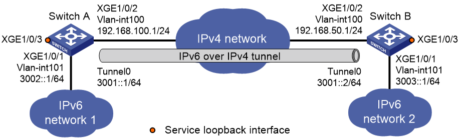
As shown in Figure 2, configure an IPv6 over IPv4 tunnel between Switch A and Switch B so the two IPv6 networks can reach each other over the IPv4 network.
Procedure
|
|
IMPORTANT: By default, interfaces on the devices are disabled (in ADM or Administratively Down state). To have an interface operate, you must use the undo shutdown command to enable that interface. |
Make sure Switch A and Switch B have the corresponding VLAN interfaces created and can reach each other through IPv4.
· Configure Switch A:
# Add Ten-GigabitEthernet 1/0/2 (the physical interface of the tunnel) to VLAN 100.
<SwitchA> system-view
[SwitchA] vlan 100
[SwitchA-vlan100] port ten-gigabitethernet 1/0/2
[SwitchA-vlan100] quit
# Specify an IPv4 address for VLAN-interface 100.
[SwitchA] interface vlan-interface 100
[SwitchA-Vlan-interface100] ip address 192.168.100.1 255.255.255.0
[SwitchA-Vlan-interface100] quit
# Add Ten-GigabitEthernet 1/0/1 to VLAN 101.
[SwitchA] vlan 101
[SwitchA-vlan101] port ten-gigabitethernet 1/0/1
[SwitchA-vlan101] quit
# Specify an IPv6 address for VLAN-interface 101.
[SwitchA] interface vlan-interface 101
[SwitchA-Vlan-interface101] ipv6 address 3002::1 64
[SwitchA-Vlan-interface101] quit
# Create service loopback group 1, and specify its service type as tunnel.
[SwitchA] service-loopback group 1 type tunnel
# Add Ten-GigabitEthernet 1/0/3 to service loopback group 1.
[SwitchA] interface ten-gigabitethernet 1/0/3
[SwitchA-Ten-GigabitEthernet1/0/3] port service-loopback group 1
[SwitchA-Ten-GigabitEthernet1/0/3] quit
# Create IPv6 over IPv4 tunnel interface Tunnel 0.
[SwitchA] interface tunnel 0 mode ipv6-ipv4
# Specify an IPv6 address for the tunnel interface.
[SwitchA-Tunnel0] ipv6 address 3001::1/64
# Specify VLAN-interface 100 as the source interface of the tunnel interface.
[SwitchA-Tunnel0] source vlan-interface 100
# Specify the destination address for the tunnel interface as the IP address of the VLAN-interface 100 on Switch B.
[SwitchA-Tunnel0] destination 192.168.50.1
[SwitchA-Tunnel0] quit
# Configure a static route destined for IPv6 network 2 through tunnel 0.
[SwitchA] ipv6 route-static 3003:: 64 tunnel 0
· Configure Switch B:
# Add Ten-GigabitEthernet 1/0/2 (the physical interface of the tunnel) to VLAN 100.
<SwitchB> system-view
[SwitchB] vlan 100
[SwitchB-vlan100] port ten-gigabitethernet 1/0/2
[SwitchB-vlan100] quit
# Specify an IPv4 address for VLAN-interface 100.
[SwitchB] interface vlan-interface 100
[SwitchB-Vlan-interface100] ip address 192.168.50.1 255.255.255.0
[SwitchB-Vlan-interface100] quit
# Add Ten-GigabitEthernet 1/0/1 to VLAN 101.
[SwitchB] vlan 101
[SwitchB-vlan101] port ten-gigabitethernet 1/0/1
[SwitchB-vlan101] quit
# Specify an IPv6 address for VLAN-interface 101.
[SwitchB] interface vlan-interface 101
[SwitchB-Vlan-interface101] ipv6 address 3003::1 64
[SwitchB-Vlan-interface101] quit
# Create service loopback group 1, and specify its service type as tunnel.
[SwitchB] service-loopback group 1 type tunnel
# Add Ten-GigabitEthernet 1/0/3 to service loopback group 1.
[SwitchB] interface ten-gigabitethernet 1/0/3
[SwitchB-Ten-GigabitEthernet1/0/3] port service-loopback group 1
[SwitchB-Ten-GigabitEthernet1/0/3] quit
# Create IPv6 over IPv4 tunnel interface Tunnel 0.
[SwitchB] interface tunnel 0 mode ipv6-ipv4
# Specify an IPv6 address for the tunnel interface.
[SwitchB-Tunnel0] ipv6 address 3001::2/64
# Specify VLAN-interface 100 as the source interface of the tunnel interface.
[SwitchB-Tunnel0] source vlan-interface 100
# Specify the destination address for the tunnel interface as the IP address of VLAN-interface 100 of Switch A.
[SwitchB-Tunnel0] destination 192.168.100.1
[SwitchB-Tunnel0] quit
# Configure a static route destined for IPv6 network 1 through tunnel 0.
[SwitchB] ipv6 route-static 3002:: 64 tunnel 0
Verifying the configuration
# Use the display ipv6 interface command to display tunnel interface status on Switch A and Switch B. Verify that the interface tunnel 0 is up. (Details not shown.)
# Verify that Switch B and Switch A can ping the IPv6 address of VLAN-interface 101 of each other. This example uses Switch A.
[SwitchA] ping ipv6 3003::1
Ping6(56 data bytes) 3001::1 --> 3003::1, press CTRL_C to break
56 bytes from 3003::1, icmp_seq=0 hlim=64 time=45.000 ms
56 bytes from 3003::1, icmp_seq=1 hlim=64 time=10.000 ms
56 bytes from 3003::1, icmp_seq=2 hlim=64 time=4.000 ms
56 bytes from 3003::1, icmp_seq=3 hlim=64 time=10.000 ms
56 bytes from 3003::1, icmp_seq=4 hlim=64 time=11.000 ms
--- Ping6 statistics for 3003::1 ---
5 packet(s) transmitted, 5 packet(s) received, 0.0% packet loss
round-trip min/avg/max/std-dev = 4.000/16.000/45.000/14.711 ms
Enabling dropping IPv6 packets that use IPv4-compatible IPv6 addresses
1. Enter system view.
system-view
2. Enable dropping IPv6 packets that use IPv4-compatible IPv6 addresses.
tunnel discard ipv4-compatible-packet
By default, IPv6 packets that use IPv4-compatible IPv6 addresses are not dropped.
IPv4 over IPv4 tunneling
About IPv4 over IPv4 tunneling
IPv4 over IPv4 tunneling (RFC 1853) enables isolated IPv4 networks to communicate. For example, an IPv4 over IPv4 tunnel can connect isolated private IPv4 networks over a public IPv4 network.
Figure 3 IPv4 over IPv4 tunnel

Figure 3 shows the encapsulation and de-encapsulation processes.
· Encapsulation:
a. Device A receives an IP packet from an IPv4 host and submits it to the IP protocol stack.
b. The IPv4 protocol stack determines how to forward the packet according to the destination address in the IP header. If the packet is destined for the IPv4 host connected to Device B, Device A delivers the packet to the tunnel interface.
c. The tunnel interface adds a new IPv4 header to the IPv4 packet and submits it to the IP protocol stack.
In the new header, the source IP address specifies the tunnel source, and the destination IP address specifies the tunnel destination.
d. The IP protocol stack uses the destination IP address of the new IP header to look up the routing table, and then sends the packet out.
· De-encapsulation:
a. After receiving the packet, Device B delivers it to the IP protocol stack.
b. If the protocol number is 4 (indicating an IPv4 packet is encapsulated within the packet), the IP protocol stack delivers the packet to the tunnel module for de-encapsulation.
c. The tunnel module de-encapsulates the IP packet and sends it back to the IP protocol stack.
d. The protocol stack forwards the de-encapsulated packet.
Restrictions and guidelines: IPv4 over IPv4 tunnel configuration
Follow these guidelines when you configure an IPv4 over IPv4 tunnel:
· The tunnel destination address specified on the local device must be identical with the tunnel source address specified on the tunnel peer device.
· Do not specify the same source and destination addresses for local tunnel interfaces in the same tunnel mode.
· The IPv4 address of the local tunnel interface cannot be on the same subnet as the destination address configured on the tunnel interface.
· To ensure correct packet forwarding, identify whether the destination IPv4 network and the IPv4 address of the local tunnel interface are on the same subnet. If they are not, configure a route reaching the destination IPv4 network through the tunnel interface. You can configure the route by using one of the following methods:
¡ Configure a static route, and specify the local tunnel interface as the egress interface or specify the IPv4 address of the peer tunnel interface as the next hop.
¡ Enable IS-IS or BGP on the tunnel interface.
The route configuration is required on both ends of the tunnel. For more information about route configuration, see Layer 3—IP Routing Configuration Guide.
· The destination address of the route passing the tunnel interface cannot be on the same subnet as the destination address configured on the tunnel interface.
Configuring an IPv4 over IPv4 tunnel
1. Enter system view.
system-view
2. Enter IPv4 over IPv4 tunnel interface view.
interface tunnel number [ mode ipv4-ipv4 ]
3. Configure an IPv4 address for the tunnel interface.
ip address ip-address { mask | mask-length } [ sub ]
4. Configure a source address or source interface for the tunnel interface.
source { ipv4-address | interface-type interface-number }
By default, no source address or source interface is configured for the tunnel interface.
If you specify a source address, it is used as the source IP address of tunneled packets.
If you specify a source interface, the primary IP address of this interface is used as the source IP address of tunneled packets.
5. Configure a destination address for the tunnel interface.
destination ipv4-address
By default, no destination address is configured for the tunnel interface.
The tunnel destination address must be the IP address of the receiving interface on the tunnel peer. It is used as the destination IP address of tunneled packets.
6. (Optional.) Set the DF bit for tunneled packets.
tunnel dfbit enable
By default, the DF bit is not set for tunneled packets.
Testing the reachability of a path
Configuring a source-destination address pair for IPv4-in-IPv4 packet decapsulation
About this task
In some scenarios, a host needs to construct multi-layer encapsulated IPv4-in-IPv4 packets to detect whether a transmission path is reachable. Use this feature on each node along the transmission path to configure a source-destination address pair used to decapsulate the IPv4-in-IPv4 packets.
A source-destination address pair contains a destination address and multiple source IP addresses. You can specify the destination address as needed, which is meaningless. You can use one of the following methods to specify multiple source IP addresses:
· Use the source ip-address option to specify a local IP address that is reachable as the source IP address.
· Use the source interface-type interface-number option to specify a source interface. The primary IP address of the interface is used as the source IP address.
· Use the source direct keyword to specify a group of source IP addresses. With this keyword, the system traverses all local Layer 3 interfaces, VLAN interfaces, and loopback interfaces in up state. The source IP addresses used for packet decapsulation are the primary IP addresses of the interfaces (except subinterfaces, interfaces in VPN instances, and inloopback interfaces).
Software version and feature compatibility
The tunnel ip-in-ip decapsulate-any command is supported only in Release 2825 and later.
Restrictions and guidelines
Configure a source-destination address pair on each node along the path to be detected. On the end node, you can specify a source IP address, a source interface, or a group of source IP addresses. On the other nodes, you must use the source direct keyword to specify a group of source IP addresses.
If you configure interfaces that borrow IP addresses to stop IP address borrowing after specifying a group of source IP addresses, the tunnel ip-in-ip decapsulate-any command no longer takes effect. For the command to take effect, you must reconfigure it. For more information about borrowing an IP address for an interface, see IP addressing in Layer 3—IP Services Configuration Guide.
Procedure
1. Enter system view.
system-view
2. Configure a source-destination address pair for IPv4-in-IPv4 packet decapsulation.
tunnel ip-in-ip decapsulate-any [ destination ip-address ] source { ip-address | interface-type interface-number | direct }
By default, no source-destination address pair is configured for IPv4-in-IPv4 packet decapsulation.
Constructing multi-layer encapsulated IPv4-in-IPv4 packets on a host
Set the destination address of a packet as the IP address of the host, and then encapsulate IP headers layer by layer to the packet.
The encapsulation order of IP headers in the IPv4-in-IPv4 packet must be opposite to the order of nodes along the path that the packet traverses. The number of encapsulated IP headers is the number of link node devices × 2 - 1.
In the IPv4-in-IPv4 packet, the source and destination addresses in an IP header must be consistent with the source-destination address pair on the node that decapsulates that IP header.
· The source address in the IP header must be the same as the destination address in the source-destination address pair.
· The destination address in the IP header must be one of the source IP addresses in the source-destination address pair.
Testing the reachability of a path
When a multi-layer encapsulated IPv4-in-IPv4 packet passes through a node, the node matches the outmost source and destination addresses of the packet with the local source-destination address pair.
· If the addresses match, the node decapsulates the outmost IP header from the packet.
· If the addresses do not match, the node does not decapsulate the outmost IP header from the packet.
After the node decapsulates the IP header, it forwards the packet to the next node according to the forwarding table. The subsequent nodes along the path successively perform the same matching and decapsulation operations as this node until the end node completes the decapsulation. Because the destination address of the original packet is the host's IP address, the end node forwards the packet back to the host.
· If the packet can return to the host, the path is reachable.
· If the packet cannot return to the host, the path is not reachable.
For example, test the reachability of a path that has two nodes. The test order is Host—>A—>B.
Figure 4 IPv4-in-IPv4 packet decapsulation workflow
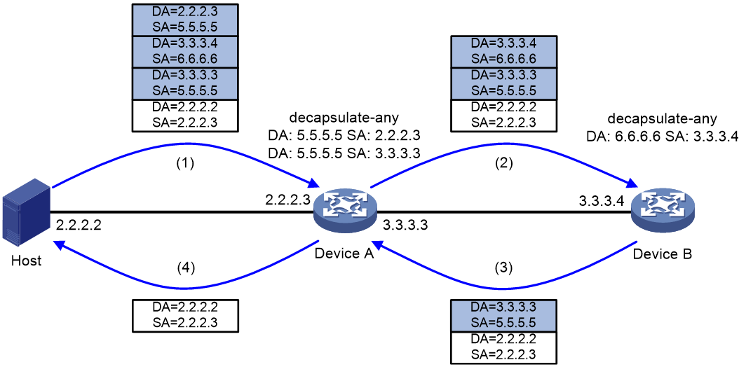
The workflow is as follows:
1. The host constructs a multi-layer decapsulated IPv4-in-IPv4 packet and sends it to Device A.
2. After receiving the packet, Device A finds that the outmost IP header of the packet matches the local source-destination address pair for IPv4-in-IPv4 packet decapsulation. Then, Device A decapsulates the outmost IP header from the packet and forwards the packet to Device B according to the forwarding table.
3. After receiving the packet, Device B finds that the outmost IP header of the packet matches the local source-destination address pair for IPv4-in-IPv4 packet decapsulation. Then, Device B decapsulates the outmost IP header from the packet and forwards the packet to the next node (Device A) according to the forwarding table.
4. Device A repeats the matching and decapsulation operations the same as Device B to decapsulate the last layer of IP header from the packet. Then, Device A forwards the packet to the host according to the forwarding table.
5. The host receives the packet or not. If the host receives the packet, the path is reachable. If the host does not receive the packet, the path is not reachable.
IPv4 over IPv4 tunnel configuration examples
Example: Configuring an IPv4 over IPv4 tunnel
Network configuration
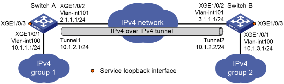
As shown in Figure 5, the two subnets IPv4 group 1 and IPv4 group 2 use private IPv4 addresses. Configure an IPv4 over IPv4 tunnel between Switch A and Switch B to make the two subnets reachable to each other.
Procedure
|
|
IMPORTANT: By default, interfaces on the devices are disabled (in ADM or Administratively Down state). To have an interface operate, you must use the undo shutdown command to enable that interface. |
Make sure Switch A and Switch B have the corresponding VLAN interfaces created and can reach each other through IPv4.
· Configure Switch A:
# Add Ten-GigabitEthernet 1/0/1 to VLAN 100.
<SwitchA> system-view
[SwitchA] vlan 100
[SwitchA-vlan100] port ten-gigabitethernet 1/0/1
[SwitchA-vlan100] quit
# Specify an IPv4 address for VLAN-interface 100.
[SwitchA] interface vlan-interface 100
[SwitchA-Vlan-interface100] ip address 10.1.1.1 255.255.255.0
[SwitchA-Vlan-interface100] quit
# Add Ten-GigabitEthernet 1/0/2 (the physical interface of the tunnel) to VLAN 101.
[SwitchA] vlan 101
[SwitchA-vlan101] port ten-gigabitethernet 1/0/2
[SwitchA-vlan101] quit
# Specify an IPv4 address for VLAN-interface 101.
[SwitchA] interface vlan-interface 101
[SwitchA-Vlan-interface101] ip address 2.1.1.1 255.255.255.0
[SwitchA-Vlan-interface101] quit
# Create service loopback group 1, and specify its service type as tunnel.
[SwitchA] service-loopback group 1 type tunnel
# Assign Ten-GigabitEthernet 1/0/3 to service loopback group 1.
[SwitchA] interface ten-gigabitethernet 1/0/3
[SwitchA-Ten-GigabitEthernet1/0/3] port service-loopback group 1
[SwitchA-Ten-GigabitEthernet1/0/3] quit
# Create IPv4 over IPv4 tunnel interface Tunnel 1.
[SwitchA] interface tunnel 1 mode ipv4-ipv4
# Specify an IPv4 address for the tunnel interface.
[SwitchA-Tunnel1] ip address 10.1.2.1 255.255.255.0
# Specify the IP address of VLAN-interface 101 as the source address for the tunnel interface.
[SwitchA-Tunnel1] source 2.1.1.1
# Specify the IP address of VLAN-interface 101 on Switch B as the destination address for the tunnel interface.
[SwitchA-Tunnel1] destination 3.1.1.1
[SwitchA-Tunnel1] quit
# Configure a static route destined for IPv4 group 2 through the tunnel interface.
[SwitchA] ip route-static 10.1.3.0 255.255.255.0 tunnel 1
· Configure Switch B:
# Add Ten-GigabitEthernet 1/0/1 to VLAN 100.
<SwitchB> system-view
[SwitchB] vlan 100
[SwitchB-vlan100] port ten-gigabitethernet 1/0/1
[SwitchB-vlan100] quit
# Specify an IPv4 address for VLAN-interface 100.
[SwitchB] interface vlan-interface 100
[SwitchB-Vlan-interface100] ip address 10.1.3.1 255.255.255.0
[SwitchB-Vlan-interface100] quit
# Add Ten-GigabitEthernet 1/0/2 (the physical interface of the tunnel) to VLAN 101.
[SwitchB] vlan 101
[SwitchB-vlan101] port ten-gigabitethernet 1/0/2
[SwitchB-vlan101] quit
# Specify an IPv4 address for VLAN-interface 101.
[SwitchB] interface vlan-interface 101
[SwitchB-Vlan-interface101] ip address 3.1.1.1 255.255.255.0
[SwitchB-Vlan-interface101] quit
# Create service loopback group 1, and specify its service type as tunnel.
[SwitchB] service-loopback group 1 type tunnel
# Assign Ten-GigabitEthernet 1/0/3 to service loopback group 1.
[SwitchB] interface ten-gigabitethernet 1/0/3
[SwitchB-Ten-GigabitEthernet1/0/3] port service-loopback group 1
[SwitchB-Ten-GigabitEthernet1/0/3] quit
# Create IPv4 over IPv4 tunnel interface Tunnel 2.
[SwitchB] interface tunnel 2 mode ipv4-ipv4
# Specify an IPv4 address for the tunnel interface.
[SwitchB-Tunnel2] ip address 10.1.2.2 255.255.255.0
# Specify the IP address of VLAN-interface 101 as the source address for the tunnel interface.
[SwitchB-Tunnel2] source 3.1.1.1
# Specify the IP address of VLAN-interface 101 on Switch A as the destination address for the tunnel interface.
[SwitchB-Tunnel2] destination 2.1.1.1
[SwitchB-Tunnel2] quit
# Configure a static route destined for IPv4 group 1 through the tunnel interface.
[SwitchB] ip route-static 10.1.1.0 255.255.255.0 tunnel 2
Verifying the configuration
# Use the display interface tunnel command to display the status of the tunnel interfaces on Switch A and Switch B. Verify that the tunnel interfaces are up. (Details not shown.)
# Verify that Switch A and Switch B can ping the IPv4 address of the peer interface VLAN-interface 100. This example uses Switch A.
[SwitchA] ping -a 10.1.1.1 10.1.3.1
Ping 10.1.3.1 (10.1.3.1) from 10.1.1.1: 56 data bytes, press CTRL_C to break
56 bytes from 10.1.3.1: icmp_seq=0 ttl=255 time=2.000 ms
56 bytes from 10.1.3.1: icmp_seq=1 ttl=255 time=1.000 ms
56 bytes from 10.1.3.1: icmp_seq=2 ttl=255 time=0.000 ms
56 bytes from 10.1.3.1: icmp_seq=3 ttl=255 time=1.000 ms
56 bytes from 10.1.3.1: icmp_seq=4 ttl=255 time=1.000 ms
--- Ping statistics for 10.1.3.1 ---
5 packet(s) transmitted, 5 packet(s) received, 0.0% packet loss
round-trip min/avg/max/std-dev = 0.000/1.000/2.000/0.632 ms