- Table of Contents
- Related Documents
-
| Title | Size | Download |
|---|---|---|
| 02-Appendix | 1.62 MB |
Contents
Appendix A Server specifications
Server models and chassis view
Front panel view of the server
Appendix B Component specifications
DDR4 DIMM rank classification label
Appendix C Managed hot removal of NVMe drives
Performing a managed hot removal in Windows
Performing a managed hot removal in Linux
Appendix D Environment requirements
About environment requirements
General environment requirements
Operating temperature requirements
Appendix A Server specifications
Figures in this document are for illustration only.
The information in this document might differ from your product if it contains custom configuration options or features.
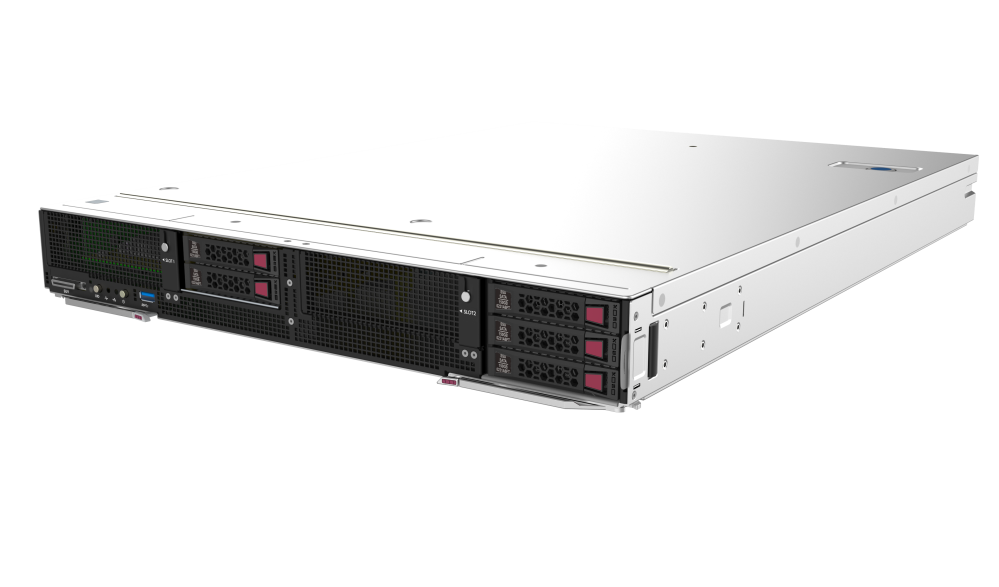
Server models and chassis view
H3C UniServer B7800 G3 blade server is an H3C-proprietary blade server with a maximum of four Intel Purley or Jintide C series processors. The server provides strong computing performance and flexible expansion capability. It can be installed in an H3C UniServer B16000 blade server enclosure and managed through the OM management module in a centralized way.
Technical specifications
|
Item |
Specifications |
|
Dimensions (H × W × D) |
· Server: 59.5 × 436 × 613.4 mm (2.34 × 17.17 × 24.15 in) · Form factor: Half height and full width · Maximum blade servers in an enclosure: 8 |
|
Max. weight |
16.5 kg (36.38 lb) |
|
Max. power |
1243 W |
|
Processors |
Maximum 4 × Intel Purley or Jintide C series processors: · Maximum 205 W power consumption per processor · Maximum 3.6 GHz frequency · Maximum 38.5 MB cache per processor |
|
Memory |
A maximum of 48 DIMMs |
|
Storage controllers |
· Embedded RSTe RAID controller · High-performance storage controller · NVMe VROC module |
|
Chipset |
Intel C621 Lewisburg chipset |
|
Network connectors |
2 × embedded 1 Gbps Ethernet ports on the chassis backplane for connecting active/standby OM modules |
|
Integrated GPU |
The GPU is integrated on the BMC management chip with chip model AST2500. The GPU provides 16 MB video memory and a maximum resolution of 1920 x 1200@60Hz (32bpp), where: · 1920 x 1200—Indicates 1920 pixels across and 1200 pixels tall. · 60 Hz—Indicates that the screen refreshes itself every 60 seconds. · 32 bpp—Indicates color depth of 32 bits per pixel. The higher the color depth, the more abundant the color. |
|
I/O connectors |
· Maximum 4 × USB connectors (one USB 3.0 connector on the front panel, one USB 3.0 connector on the system board, two USB 2.0 connectors expanded by using SUV cables on the front panel) · 1 × VGA connector (expanded by using the SUV cable) · 1 × serial port connector (expanded by using the SUV cable) · 2 × SATA M.2.0 SSD connectors · 2 × Micro SD card connectors (on the system board) The Micro SD cards can use the memory chip on the system board to form a RAID 1 array. The RAID level cannot be modified. |
|
PCIe connectors |
Maximum 9 × PCIe 3.0 connectors (one for a storage controller, two for standard PCIe modules, and six for mezzanine modules) |
Components
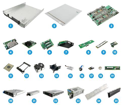
Figure 2 H3C B7800 G3 blade server components
|
Item |
Description |
|
(1) Blade server chassis |
Centralizes blade server components. |
|
(2) Chassis access panel |
N/A. |
|
(3) System board |
One of the most important parts of a server, on which multiple components are installed, such as a processor, memory, and PCIe module. It is integrated with basic server components, including the BIOS chip, HDM chip, and PCIe connectors. |
|
(4) Mezzanine module |
Refers to PCIe modules connected by the mezzanine connectors. The mezzanine network adapters are connected to ICMs at the server rear to realize the interaction between a blade server and client. |
|
(5) Storage controller |
Provides RAID capability to SAS/SATA drives, including RAID configuration and RAID scale-up. It supports online upgrade of the controller firmware and remote configuration. |
|
(6) Drive backplane |
Provides power and data channels for drives. |
|
(7) PCIe riser card |
Provides PCIe slots. |
|
(8) Direct connect card |
Connects embedded soft RAID and SATA drives. |
|
(9) SATA M.2 SSD |
Provides data storage space. |
|
(10) TPM/TCM module |
Provides encryption services for the server to enhance data security. |
|
(11) Processor |
Integrates memory and PCIe controllers to provide data processing capabilities for the server. |
|
(12) Processor retaining bracket |
Attaches a processor to the heatsink. |
|
(13) Processor heatsink |
Cools the processor. |
|
(14) Processor socket |
Provides protection to the processor pins and ventilation aisles for the processor. |
|
(15) Supercapacitor |
Supplies power to the flash card on the power fail safeguard module, which enables the storage controller to back up data to the flash card for protection when power outage occurs. |
|
(16) NVMe VROC module |
Works with Intel VMD to provide RAID capability for the server to virtualize storage resources of NVMe drives. |
|
(17) Micro SD card |
Provides data storage space. |
|
(18) System battery |
Powers the system clock to ensure a correct system date and time. |
|
(19) Memory |
Stores computing data and data exchanged with external storage temporarily. |
|
(20) SATA M.2 SSD adapter module |
Provides M.2 SSD module slots, and supports hot swapping. |
|
(21) SATA M.2 SSD module |
Provides data storage space, and supports hot swapping. |
|
(22) Drive |
Provides data storage space, and supports hot swapping. |
|
(23) Drive cage |
Expands drives. |
|
(24) Air baffle |
Provides ventilation aisles. |
|
(25) Riser card blank |
Installed on an empty PCIe riser connector to ensure good ventilation. |
Front panel
Front panel view of the server
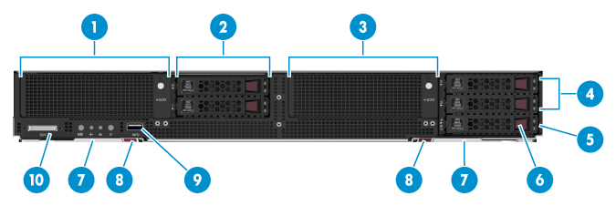
Table 1 Front panel description
|
Item |
Description |
|
1 |
PCIe module (for processor 2) (optional) |
|
2 |
SAS/SATA HHDs/SSDs or NVMe drives |
|
3 |
PCIe module (for processor 3) (optional) |
|
4 |
SAS/SATA HHDs/SSDs or NVMe drives |
|
5 |
Serial label pull tab |
|
6 |
SAS/SATA HHD/SSD or SATA M.2 SSD module (connected by using the SATA M.2 SSD adapter module) |
|
7 |
Locking levers |
|
8 |
Buttons for releasing the locking levers |
|
9 |
USB 3.0 connector (connecting USB drives, USB mousse or keyboards, or USB optical drives for OS installation) |
|
7 |
SUV connector |
LEDs and buttons
Figure 4 shows the front panel LEDs and buttons. Table 2 describes the status of the front panel LEDs.
Figure 4 Front panel LEDs and buttons
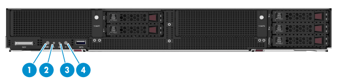
Table 2 LEDs and buttons on the front panel
|
Item |
Button/LED |
Status |
|
1 |
UID button LED |
· Steady blue—UID LED is activated. The UID LED can be activated by using the following methods: ¡ Press the UID button LED. ¡ Activate the UID LED from HDM. · Flashing blue: ¡ 1 Hz—The firmware is being upgraded or the system is being managed from HDM. Do not power off the server. ¡ 4 Hz—HDM is restarting. To restart HDM, press the UID button LED for ten seconds. · Off—UID LED is not activated. |
|
2 |
Health LED |
· Steady green—The system is operating correctly. · Flashing green (4 Hz)—HDM is initializing. · Flashing amber (0.5 Hz)—A predictive alarm is present. · Flashing amber (1 Hz)—A minor alarm is present. · Flashing red (1 Hz)—A critical alarm is present. If a system alarm is present, log in to HDM to obtain more information about the system running status. |
|
3 |
Embedded GE network adapter LED |
· Steady green—A link is present on the port. · Flashing green (1 Hz)—The port is receiving or sending data. · Off—No link is present on the port. |
|
4 |
Power on/standby button and system power LED |
· Steady green—The system has started. · Flashing green (1 Hz)—The system is starting. · Steady amber—The system is in standby state. · Off—No power is present. Possible reasons: ¡ No power source is connected. ¡ No power supplies are present. ¡ The installed power supplies are faulty. |
SUV cable
A SUV cable can be connected to the front panel to provide two USB 2.0 connectors, one serial port, and one VGA connector.
Figure 5 SUV cable
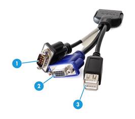
Table 3 SUV cable connectors
|
Item |
Description |
Application |
|
1 |
Serial port |
Diagnoses faults and debugs devices. |
|
2 |
VGA connector |
Connects terminal displays such as monitors or KVM devices. |
|
3 |
2 × USB 2.0 connectors |
The extended USB 2.0 connectors and USB 3.0 connector that comes with the default configuration are all available for the following USB devices: · USB drives. · USB keyboards or mouses. · USB optical drives for installing operating systems. |
Serial label pull tab
The serial label pull tab is on the front panel, as shown by the callout 5 in Figure 3. It provides the following information about the server:
· User information. Users can scan the QR code to access the product document center, and view documents for the blade server.
· HDM default information.
· Product serial number.
· Server model.
System board components
System board layout
Figure 6 System board layout
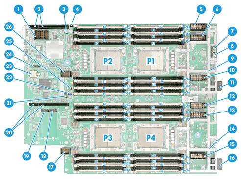
Table 4 System board components
|
Item |
Description |
|
1 |
Storage controller connector |
|
2 |
PCIe riser connector 1 (for processor 2) |
|
3 |
System maintenance switch 3 |
|
4 |
NVMe VROC module connector |
|
5 |
Mezzanine module connector 6 (for processor 1, ICM 3/6) |
|
6 |
Mezzanine module connector 5 (for processor 2, ICM 2/5) |
|
7 |
Micro SD card connector 2 |
|
8 |
Micro SD card connector 1 |
|
9 |
Mezzanine module supporting bracket 2 |
|
10 |
Mezzanine module connector 4 (for processor 1, ICM 1/4) |
|
11 |
Backplane connector 2 |
|
12 |
Mezzanine module connector 3 (for processor 4, ICM 3/6) |
|
13 |
Mezzanine module connector 2 (for processor 3, ICM 2/5) |
|
14 |
Mezzanine module supporting bracket 1 |
|
15 |
Mezzanine module connector 1 (for processor 4, ICM 1/4) |
|
16 |
Backplane connector 1 |
|
17 |
Drive backplane connector 2 |
|
18 |
SATA M.2 SSD module connector 1 |
|
19 |
SATA M.2 SSD module connector 2 |
|
20 |
PCIe riser connector 2 (for processor 3) |
|
21 |
System maintenance switch 2 |
|
22 |
USB 3.0 connector |
|
23 |
System battery |
|
24 |
TPM/TCM connector |
|
25 |
System maintenance switch 1 |
|
26 |
Drive backplane connector 1 |
System maintenance switch
Table 5 describes how to use the maintenance switch. For more information about the position of the maintenance switch, see "System board components".
Table 5 System maintenance switch description
|
Item |
Description |
Remarks |
|
1 |
· Pins 1, 2, 3, 4, 5, 6, and 7 are reserved for future use. · Pin 8: ¡ Off (default)—HDM login requires the username and password of a valid HDM user account. ¡ On—HDM login requires the default username and password. |
For security purposes, turn off the switch after you complete tasks with the default username and password as a best practice. |
|
2 |
· Pins 1-2 jumped (default)—Normal server startup. · Pins 2-3 jumped—Restores the default BIOS settings. |
To restore the default BIOS settings, jump pins 2 and 3 for more than 30 seconds and then jump pins 1 and 2 for normal server startup. |
|
3 |
· Pins 1-2 jumped (default)—Normal server startup. · Pins 2-3 jumped—Clears all passwords from the BIOS at server startup. |
To clear all passwords from the BIOS, jump pins 2 and 3 for over 30 seconds and then jump pins 1 and 2 for normal server startup. |
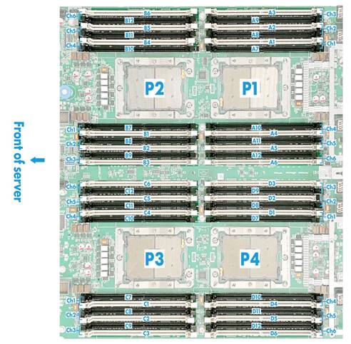
DIMM slots
The system board provides six DIMM channels per processor, and a maximum of 24 channels in total, as shown in Figure 7. Each channel contains two DIMM slots.
Figure 7 System board DIMM slot layout
PCIe connectors
Table 6 shows information about supported PCIe devices, corresponding processors, PCIe standard, PCIe connector physical bandwidth and bus bandwidth, and PCIe device form factor.
Table 6 PCIe devices and slave processors
|
PCIe device |
Processor |
PCIe standard |
PCIe connector physical bandwidth |
PCIe connector bus bandwidth |
PCIe device form factor |
|
NVMe drive 0 |
Processor 2 |
PCIe 3.0 |
x4 |
x4 |
2.5 inches |
|
NVMe drives 1 |
Processor 2 |
PCIe 3.0 |
x4 |
x4 |
2.5 inches |
|
NVMe drives 2 |
Processor 3 |
PCIe 3.0 |
x4 |
x4 |
2.5 inches |
|
NVMe drives 3 |
Processor 3 |
PCIe 3.0 |
x4 |
x4 |
2.5 inches |
|
Riser card 1 |
Processor 2 |
PCIe 3.0 |
x16 or 2*x8 |
x16 or 2*x8 |
Supports installing an LP PCIe module or a non-standard P6 GPU |
|
Riser card 2 |
Processor 3 |
PCIe 3.0 |
x16 or 2*x8 |
x16 or 2*x8 |
Supports installing an LP PCIe module or a non-standard P6 GPU |
|
Storage controller |
Processor 1 |
PCIe 3.0 |
x8 |
x8 |
Non-standard component |
|
Mezzanine module 1 |
Processor 4 |
PCIe 3.0 |
x16 or 2*x8 |
x16 or 2*x8 |
Non-standard component |
|
Mezzanine module 2 |
Processor 3 |
PCIe 3.0 |
x16 or 2*x8 |
x16 or 2*x8 |
Non-standard component |
|
Mezzanine module 3 |
Processor 4 |
PCIe 3.0 |
x16 or 2*x8 |
x16 or 2*x8 |
Non-standard component |
|
Mezzanine module 4 |
Processor 1 |
PCIe 3.0 |
x16 or 2*x8 |
x16 or 2*x8 |
Non-standard component |
|
Mezzanine module 5 |
Processor 2 |
PCIe 3.0 |
x16 or 2*x8 |
x16 or 2*x8 |
Non-standard component |
|
Mezzanine module 6 |
Processor 1 |
PCIe 3.0 |
x16 or 2*x8 |
x16 or 2*x8 |
Non-standard component |
|
|
NOTE: · If a processor is absent, the corresponding PCIe devices are not available. · For more information about drive numbering, see "Drive numbering." · Riser card 1 indicates that the riser card is installed on PCIe riser connector 1 on the system board and mezzanine module 1 indicates that the mezzanine module is installed on mezzanine connector 1 on the system board.. |
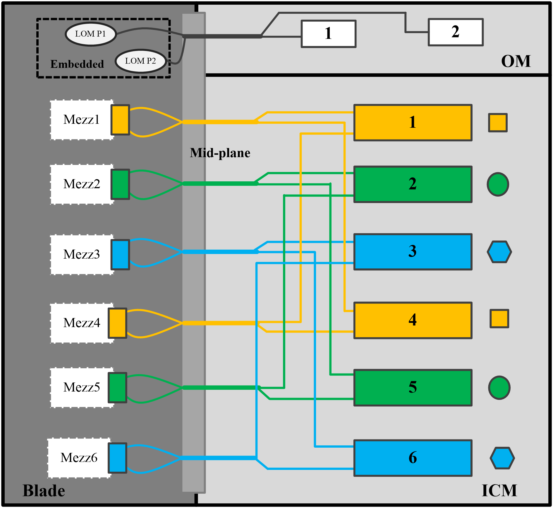
Internal networking
Blade servers can access the network through either of the following methods:
· Connecting the embedded network adapters to the active and standby OMs.
· Connecting the Mezzanine modules to ICMs.
ICMs connect to blade servers through the mid plane and provide uplink interfaces. The server supports a maximum of 6 mezzanine modules. The chassis supports a maximum of 6 ICMs, which are divided into three interconnected pairs (ICMs in slots 1 and 4, 2 and 5, 3 and 6). Each ICM pair operates as a switching plane and users can configure modules in each pair to operate in active/standby mode as needed. For more information about ICM positions, see the user guide for the chassis.
¡ Mezzanine modules 1 and 4 are connected to ICMs in slots 1 and 4.
¡ Mezzanine modules 2 and 5 are connected to ICMs in slots 2 and 5.
¡ Mezzanine modules 3 and 6 are connected to ICMs in slots 3 and 6.
Figure 8 Internal networking of a blade server
Storage requirements
Follow these guidelines to store storage media:
· As a best practice, do not store an HDD for 6 months or more without powering on and using it.
· As a best practice, do not store an SSD, M.2 SSD, or SD card for 3 months or more without powering on and using it. Long unused time increases data loss risks.
· To store the server chassis, or an HDD, SSD, M.2 SSD, or SD card for 3 months or more, power on it every 3 months and run it for a minimum of 2 hours each time. For information about powering on and powering off the server, see "Powering on and powering off the blade server."
Appendix B Component specifications
For components compatible with the server and detailed component information, contact Technical Support.
HDDs and SSDs
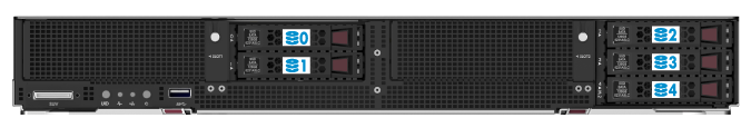
Drive numbering
The blade server provides drive number (drive slot number) marks on the front and rear panels to help identify drives, as shown in Figure 4.
When two SATA M.2 SSD modules are installed in slot 4, the numbers of the two modules are 4 and 5 from left to right.
Figure 9 Drive numbering at the front
Drive LEDs
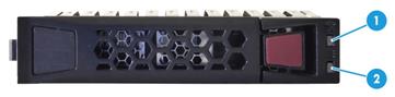
The blade server supports SAS, SATA, and NVMe drives. You can use the LEDs on a drive to identify its status after it is connected to a storage controller.
Figure 5 shows the location of the LEDs on a drive.
|
(1) Fault/UID LED |
(2) Present/Active LED |
To identify the status of a SAS or SATA drive, use Table 7. To identify the status of an NVMe drive, use Table 8.
Table 7 SAS/SATA drive LED description
|
Fault/UID LED status |
Present/Active LED status |
Description |
|
Flashing amber (0.5 Hz) |
Steady/Flashing green (4.0 Hz) |
A drive failure is predicted. As a best practice, replace the drive before it fails. |
|
Steady amber |
Steady/Flashing green (4.0 Hz) |
The drive is faulty. Replace the drive immediately. |
|
Steady blue |
Steady/Flashing green (4.0 Hz) |
The drive is operating correctly and is selected by the RAID controller. |
|
Off |
Flashing green (4.0 Hz) |
The drive is performing a RAID migration or rebuilding, or the system is reading or writing data to the drive. |
|
Off |
Steady green |
The drive is present but no data is being read or written to the drive. |
|
Off |
Off |
The drive is not securely installed. |
Table 8 NVMe drive LED description
|
Fault/UID LED status |
Present/Active LED status |
Description |
|
Flashing amber (0.5 Hz) |
Off |
The managed hot removal is complete, and you are allowed to remove the drive. |
|
Flashing amber (4.0 Hz) |
Off |
The drive is in hot insertion. |
|
Steady amber |
Steady/Flashing green (4.0 Hz) |
The drive is faulty. Replace the drive immediately. |
|
Steady blue |
Steady/Flashing green (4.0 Hz) |
The drive is operating correctly and is selected by the RAID controller. |
|
Off |
Flashing green (4.0 Hz) |
The drive is performing a RAID migration or rebuilding, or the system is reading or writing data to the drive. |
|
Off |
Steady green |
The drive is present but no data is being read or written to the drive. |
|
Off |
Off |
The drive is not securely installed. |
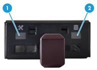
SATA M.2 SSD module LEDs
Use the LEDs on the front panel of the SATA M.2 SSD module to identify its status.
Figure 6 shows the location of LEDs on the front panel.
Figure 11 SATA M.2 SSD module LEDs
|
(1) Fault/UID LED |
(2) Present/Active LED |
Table 9 SATA M.2 SSD module LED description
|
Fault/UID LED status |
Present/Active LED status |
Description |
|
Flashing amber (0.5 Hz) |
Steady/Flashing green (4 Hz) |
An M.2 SSD module failure is predicted. As a best practice, replace the drive before it fails. |
|
Steady amber |
Steady/Flashing green (4 Hz) |
An M.2 SSD module is faulty. Replace the drive immediately. |
|
Steady blue |
Steady/Flashing green (4 Hz) |
An M.2 SSD module is operating correctly and is selected by the RAID controller. |
|
Off |
Flashing green (4 Hz) |
An M.2 SSD module is performing a RAID migration or rebuilding, or the system is reading or writing data to the drive. |
|
Off |
Steady green |
An M.2 SSD module drive is present but no data is being read or written to the drive. |
|
Off |
Off |
An M.2 SSD module drive is not securely installed. |
DIMMs
The blade server provides six DIMM channels per processor and each channel has two DIMM slots. If the server has two processors, the total number of DIMM slots is 24. If the server has four processors, the total number of DIMM slots is 48. The support for DIMMs varies by CPU brand.
DDR4 DIMM rank classification label
A DIMM rank is a set of memory chips that the system accesses while writing or reading from the memory. On a multi-rank DIMM, only one rank is accessible at a time.
To determine the rank classification of a DDR4 DIMM, use the label attached to the DIMM, as shown in Figure 7.
Figure 12 DIMM rank classification label
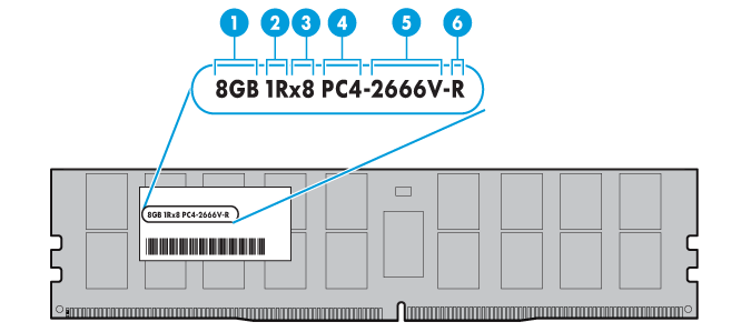
Table 10 DIMM rank classification label description
|
Callout |
Description |
Remarks |
|
1 |
Capacity |
Options include: · 8GB. · 16GB. · 32GB. |
|
2 |
Number of ranks |
Options include: · 1R— One rank (Single-Rank). · 2R—Two ranks (Dual-Rank). A 2R DIMM is equivalent to two 1R DIMMs. · 4R—Four ranks (Quad-Rank). A 4R DIMM is equivalent to two 2R DIMMs · 8R—Eight ranks (8-Rank). An 8R DIMM is equivalent to two 4R DIMMs. |
|
3 |
Data width |
Options include: · ×4—4 bits. · ×8—8 bits. |
|
4 |
DIMM generation |
Only DDR4 is supported. |
|
5 |
Data rate |
Options include: · 2133P—2133 MHz. · 2400T—2400 MHz. · 2666V—2666 MHz. · 2933Y—2933 MHz. |
|
6 |
DIMM type |
Options include: · L—LRDIMM. · R—RDIMM. |
For DCPMM DIMMs, the rank classification label only displays DCPMM DIMM capacity. For more information, contact Technical Support.
Appendix C Managed hot removal of NVMe drives
Before you begin
A managed hot removal of the NVMe drive needs to be performed in specific operating systems. Make sure VMD is enabled (configured as Auto or Enabled). For more information about VMD, see the BIOS user guide for the server. To perform a managed hot removal of the NVMe drive when VMD is disabled, contact H3C Support.
When VMD is configured as Auto or Enabled, NVMe drive hot removal is not supported in SLES operating systems.
Removing an NVMe drive
Performing a managed hot removal in Windows
1. Stop the services on the NVMe drive.
2. Identify the location of the NVMe drive to be removed on the server. For more information, see "Drive numbering."
3. Run Intel® Rapid Storage Technology enterprise to view running NVMe drives on the server, as shown by callout 2 in Figure 8.
|
|
IMPORTANT: Install and use Intel® Rapid Storage Technology enterprise according to the guide provided with the tool kit. To obtain Intel® Rapid Storage Technology enterprise, use one of the following methods: · Go to https://platformsw.intel.com/KitSearch.aspx to download the software. · Contact Intel Support. |
4. Click Activate LED to turn on the Fault/UID LED on the drive, as shown by callout 2 in Figure 8.
5. Click Remove Disk, as shown by callout 3 in Figure 8.
Figure 13 Removing the NVMe drive

6. Observe the LEDs on the NVMe drive. Make sure the Fault/UID LED is steady blue.
7. Make sure the NVMe drive is removed from the Devices list of Intel® Rapid Storage Technology enterprise.
8. Remove the NVMe drive. For more information about the removal procedure, see "Removing an NVMe drive."
Performing a managed hot removal in Linux
1. Stop the services on the NVMe drive.
2. Identify the name of the NVMe drive to be removed. For more information, see "Drive numbering."
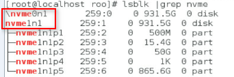
3. Execute the lsblk | grep nvme command to identify the drive letter of the NVMe drive to be removed.
This procedure uses drive nvme0n1 as an example.
Figure 14 Identifying the name of the NVMe drive to be removed
4. Execute the ledctl locate=/dev/nvme0n1 command to turn on the Fault/UID LED on the drive.
5. Execute the echo 1 > /sys/block/nvme0n1/device/device/remove command to unmount drive nvme0n1 from the operating system.
6. Observe the LEDs on the NVMe drive. You can remove the NVMe drive after the Fault/UID LED turns steady amber.
7. Remove the NVMe drive. For more information about the removal procedure, see "Removing an NVMe drive."
Appendix D Environment requirements
About environment requirements
The operating temperature requirements for the server vary depending on the server model and hardware configuration. When the general and component-based requirements conflict, use the component-based requirement.
Be aware that the actual maximum operating temperature of the server might be lower than what is stated because of poor site cooling performance. In a real data center, the server cooling performance might decrease because of adverse external factors, including poor cabinet cooling performance, high power density inside the cabinet, or insufficient spacing between devices.
General environment requirements
|
Item |
Specifications |
|
Operating temperature |
Minimum: 5°C (41°F) Maximum: 45°C (113°F)
The maximum temperature varies by hardware option presence. For more information, see "Operating temperature requirements." |
|
Storage temperature |
–40°C to +70°C (–40°F to +158°F) |
|
Operating humidity |
8% to 90%, noncondensing |
|
Storage humidity |
5% to 95%, noncondensing |
|
Operating altitude |
–60 m to +5000 m (–196.85 ft to +16404.20 ft) The allowed maximum temperature decreases by 0.33 °C (32.59 °F) as the altitude increases by 100 m (328.08 ft) from 900 m (2952.76 ft). HDD drives are not supported at an altitude over 3000 m (9842.52 ft). |
|
Storage altitude |
–60 m to +5000 m (–196.85 ft to +16404.20 ft) |
Operating temperature requirements
Table 11 Operating temperature requirements
|
Maximum server operating temperature |
Hardware options |
|
35°C (95°F) |
· When processors with a TDP no less than 200 W are configured, PCIe modules such as PCIe network adapters that have output ports at the front are not supported. · When PCIe modules that have output ports at the front are configured, only processors with a TDP not more than 165 W are supported. · When GPU-P6 and GPU-T4 are configured, only processors with a TDP not more than 165 W are supported. In the above situations, when one fan fails, the maximum operating temperature drops to 30 °C (86°F). |
|
40°C (104°F) |
· Only processors with a TDP not more than 165 W are supported. · PCIe modules such as PCIe network adapters that have output ports at the front are not supported. · GPU-P6 and GPU-T4 are not supported. · With processor 6246, 6146, and 6144 configured, when one fan fails, the maximum operating temperature drops to 35°C (95°F). |
|
45°C (113°F) |
· Processors with a TDP not more than 150 W are supported excluding processor 6252, 6240, 6148, 6136, 6128, 6144, 5222, 5122, 5220R, 6126T, 6208U, 6226R, and 8160T. · SATA M.2 SSD modules are not supported. · 128G memory modules are not supported. |
|
|
NOTE: · Some processors mentioned in this table are not supported. For processor compatibility, contact Technical Support. · For more information about positions of PCIe riser connectors, see "System board components." |
Appendix E Product recycling
New H3C Technologies Co., Ltd. provides product recycling services for its customers to ensure that hardware at the end of its life is recycled. Vendors with product recycling qualification are contracted to New H3C to process the recycled hardware in an environmentally responsible way.
For product recycling services, contact New H3C at
· Tel: 400-810-0504
· E-mail: [email protected]
· Website: http://www.h3c.com
Appendix F Glossary
|
Description |
|
|
A |
|
|
ADR |
Asynchronous DRAM Refresh is a platform process which flushes the data in ADR protected write buffers to DCPMM when the system power unit detects power loss from the AC power supply. |
|
B |
|
|
BIOS |
Basic input/output system is non-volatile firmware pre-installed in a ROM chip on a server's management module. The BIOS stores basic input/output, power-on self-test, and auto startup programs to provide the most basic hardware initialization, setup and control functionality. |
|
E |
|
|
Ethernet adapter |
An Ethernet adapter, also called a network interface card (NIC), connects the server to the network. |
|
G |
|
|
GPU module |
Graphics processing unit module converts digital signals to analog signals for output to a display device and assists processors with image processing to improve overall system performance. |
|
H |
|
|
HDM |
Hardware Device Management is the server management control unit with which administrators can configure server settings, view component information, monitor server health status, and remotely manage the server. |
|
Hot swapping |
A module that supports hot swapping (a hot-swappable module) can be installed or removed while the server is running without affecting the system operation. |
|
K |
|
|
KVM |
KVM is a management method that allows remote users to use their local video display, keyboard, and mouse to monitor and control the server. |
|
N |
|
|
NVMe VROC module |
A module that works with Intel VMD to provide RAID capability for the server to virtualize storage resources of NVMe drives. |
|
R |
|
|
RAID |
Redundant array of independent disks (RAID) is a data storage virtualization technology that combines multiple physical hard drives into a single logical unit to improve storage and security performance. |
|
Redundancy |
A mechanism that ensures high availability and business continuity by providing backup modules. In redundancy mode, a backup or standby module takes over when the primary module fails. |
Appendix G Acronyms
|
Acronym |
Full name |
|
A |
|
|
ADR |
Asynchronous DRAM Refresh |
|
B |
|
|
BIOS |
Basic Input/Output System |
|
C |
|
|
CPU |
Central Processing Unit |
|
D |
|
|
DCPMM |
Data Center Persistent Memory Module |
|
DDR |
Double Data Rate |
|
DIMM |
Dual Inline Memory Module |
|
DRAM |
Dynamic Random Access Memory |
|
G |
|
|
GPU |
Graphics Processing Unit |
|
H |
|
|
HBA |
Host Bus Adapter |
|
HDD |
Hard Disk Drive |
|
HDM |
Hardware Device Management |
|
I |
|
|
ICM |
Interconnect Module |
|
L |
|
|
LFF |
Large Form Factor |
|
LRDIMM |
Load Reduced Dual Inline Memory Module |
|
N |
|
|
NVMe |
Non-Volatile Memory Express |
|
O |
|
|
OM |
Onboard Management |
|
P |
|
|
PCIe |
Peripheral Component Interconnect Express |
|
R |
|
|
Redundant Arrays of Independent Disks |
|
|
RDIMM |
Registered Dual Inline Memory Module |
|
S |
|
|
SAS |
Serial Attached Small Computer System Interface |
|
SATA |
Serial ATA |
|
SD |
Secure Digital |
|
SFF |
Small Form Factor |
|
SSD |
Solid State Drive |
|
T |
|
|
TCM |
Trusted Cryptography Module |
|
TDP |
Thermal Design Power |
|
TPM |
Trusted Platform Module |
|
U |
|
|
UID |
Unit Identification |
|
UPI |
Ultra Path Interconnect |
|
USB |
Universal Serial Bus |
|
V |
|
|
VROC |
Virtual RAID on CPU |
|
VMD |
Volume Management Device |
