- Table of Contents
- Related Documents
-
| Title | Size | Download |
|---|---|---|
| 01-Text | 956.00 KB |
Overview
The power modules support 1+1 redundancy and load sharing and are removable. They also provide output overcurrent, output overvoltage, output short circuit, and overtemperature protections.
Front panel
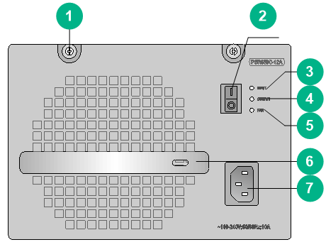
Figure 1 PSR650C-12A front panel
|
(1) Captive screw |
(2) Power switch |
|
(3) Power input LED |
(4) Power output LED |
|
(5) Fan status LED |
(6) Handle |
|
(7) Power receptacle |
|
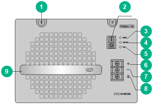
Figure 2 PSR650C-12D front panel
|
(1) Captive screw |
(2) Power switch |
|
(3) Power input LED |
(4) Power output LED |
|
(5) Fan status LED |
|
|
(6) DC input positive terminal (+) |
|
|
(7) DC input negative terminal (–) |
(8) Grounding point |
|
(9) Handle |
|
Technical specifications
Table 1 Technical specifications
|
Item |
PSR650C-12A |
PSR650C-12D |
|
Rated input voltage |
100 to 240 VAC @ 50 or 60 Hz |
–48 to –60 VDC |
|
Output voltage |
12 V |
12 V |
|
Max output current |
54 A |
54 A |
|
Max output power |
650 W |
650 W |
|
Dimensions (H × W × D) |
128 × 196 × 382 mm (5.04 × 7.72 × 15.04 in) |
128 × 196 × 382 mm (5.04 × 7.72 × 15.04 in) |
|
Weight |
4.70 kg (10.36 lb) |
4.20 kg (9.26 lb) |
|
Operating temperature |
–10°C to +55°C (14°F to 131°F) |
–10°C to +55°C (14°F to 131°F) |
|
Operating humidity |
5% RH to 95% RH |
5% RH to 95% RH |
LEDs
The PSR650C-12A/PSR650C-12D power module provides three red-green status LEDs.
Table 2 LED description
|
LED |
Status |
Description |
|
INPUT |
Green |
The power is being input correctly. |
|
Red |
A power input problem has occurred because the input voltage is out of the rated voltage range. |
|
|
Off |
No power is being input because one of the following conditions exists: · The power module is faulty. · The power cord is disconnected. · The power source is unavailable. |
|
|
OUTPUT |
Green |
The power is being output correctly. |
|
Red |
A power output problem has occurred because one of the following conditions exists: · The power module generates an alarm and enters protection state because of input undervoltage, output short circuit, output overcurrent, output overvoltage, overtemperature, or fan failure. · The power module is switched off. |
|
|
Off |
No power is being output because one of the following conditions exists: · The power module is faulty. · The power cord is disconnected. · The power source is unavailable. |
|
|
FAN |
Green |
The fans are operating correctly. |
|
Red |
The fans are operating incorrectly because one of the following conditions exists: · A fan failure has occurred. · The power module is switched off. |
|
|
Off |
The fans stop operating because one of the following conditions exists: · The power module is faulty. · The power cord is disconnected. · The power source is unavailable. |
Installing and removing the power module
The installation and removal procedures are the same for the PSR650C-12A and PSR650C-12D power modules. This section uses the PSR650C-12A as an example.
Safety precautions
To avoid possible bodily injury and power module and device damage, follow these safety precautions:
· When you install and remove the power module, always wear an ESD wrist strap and make sure it makes good skin contact and is reliably grounded.
· Before you install the power module, make sure the output voltage of the power module is as required by the device.
· When you move the power module, support its bottom instead of only holding the power handle.
· To avoid device damage, do not install power modules of different models on the same device.
· Do not touch any bare cables or terminals of the power module.
· Do not place the power module in a wet area, and prevent liquid from flowing into the power module.
· Do not open the power module. When the internal circuits or components of the power module fail, contact H3C Support.
Installing the power module
|
WARNING! Turn off the power switch before installing the power module. |
To avoid bodily injury and device damage, follow the procedure in Figure 3 to install a power module.
Figure 3 Power module installation procedure
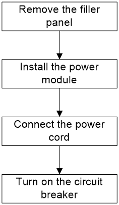
1. Wear an ESD wrist strap, and make sure the strap makes good skin contact and is reliably grounded.
2. Remove the filler panel, if any, from the target slot.
Keep the removed filler panel for future use.
3. Unpack the power module. Make sure the power module model is as required.
4. Correctly orient the power module.
If you encounter a hard resistance while inserting the power module or fastening a captive screw, pull out the power module, reorient it, and then insert it again.
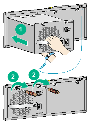
Figure 4 Installing the power module
Removing the power module
To avoid device damage and bodily injury, follow the procedure in Figure 5 to remove the power module.
Figure 5 Power module removal procedure
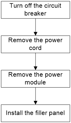
1. Turn off the circuit breaker of the power cord.
2. Prepare an antistatic mat to place the removed power module.
3. Wear an ESD wrist strap, and make sure the strap makes good skin contact and is reliably grounded.
4. Switch off the power module.
5. Remove the power cord connected to the power module.
6. Use a Phillips screwdriver to loosen the captive screws on the power module.
7. Holding the power module handle with one hand and supporting the bottom of the power module with the other, gently pull the power module out.
8. Put the removed power module on the antistatic mat.
9. If you are not to install a new power module, install a filler panel over the empty power module slot.
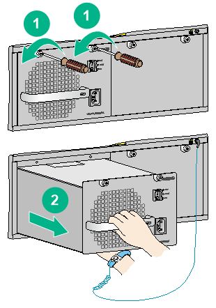
Figure 6 Removing the power module
Connecting the power cord
Connecting the AC power cord
|
|
WARNING! - Make sure each power module has a separate circuit breaker. - Turn off the circuit breaker before connecting the power cord. |
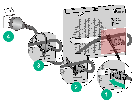
To connect the AC power cord:
1. Unpack the power cord, and verify that the power cord model is correct.
2. Connect the power cord to the power receptacle of the power module. Make sure the power cord is securely inserted into the power receptacle.
3. Use a cable tie to secure the power cord to the handle of the power module.
4. Connect the other end of the power cord to the AC power source.
Figure 7 Connecting the AC power cord
Connecting the DC power cord
|
|
WARNING! - Make sure each power module has a separate circuit breaker. - Turn off the circuit breaker before connecting the power cord. |
To connect the DC power cord:
1. Remove the protection cover from the power module.
2. Remove the screw on the wiring terminal with a Phillips screwdriver.
3. Connect one ends of the wires to the power input terminals on the power module, with the negative wire (– or L–) to the negative terminal (–) and the positive wire (+ or M/N) to the positive terminal (+).
4. Put the protection cover on the wiring terminals.
5. Connect the other ends of the wires to the DC power source wiring terminals, with the negative wire (– or L–) to the negative terminal (–) and the positive wire (+ or M/N) to the positive terminal (+).
Figure 8 Connecting the DC power cord
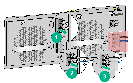
|
|
NOTE: The power cord color code scheme in Figure 8 is for illustration only. The cord delivered for your country or region might use a different color scheme. When you connect a power cord, always identify the polarity symbol on its wires. |
