- Table of Contents
- Related Documents
-
| Title | Size | Download |
|---|---|---|
| 05-MOD configuration | 123.80 KB |
Software version compatibility with MOD
Restrictions and guidelines: MOD configuration
Display and maintenance commands for MOD
Example: Configuring MOD to send packets through UDP
Example: Configuring MOD to send packets through gRPC
Configuring MOD
Overview
Mirror On Drop (MOD) can detect packet drops during the forwarding process on the device. When a packet is dropped, MOD can send the packet drop reason and the characteristics of the dropped packet to the collector.
MOD uses the flow entries generated based on a flow group to detect dropped packets. For more information about flow groups, see flow group configuration in Telemetry Configuration Guide.
MOD works as follows:
1. The device generates flow entries based on a flow group.
2. Based on the packet drop reason list of MOD, the device monitors packet drops for packets matching the flow entries.
3. If a packet is dropped for a reason on the packet drop reason list, the device sends the packet drop reason and the characteristics of the dropped packet (flow entry matching the packet) to the collector.
Software version compatibility with MOD
This feature is supported only in Release 6616 and later.
Restrictions and guidelines: MOD configuration
MOD takes effect only on packets matching ACLs referenced by flow groups.
MOD monitors only packets dropped for reasons on the configured packet drop reason list. MOD does not monitor packets dropped for other reasons.
You can enable sampling for only one of the following features on the device:
· MOD.
· NetStream.
· IPv6 NetStream.
· Mirroring.
· sFlow.
· INT.
· Telemetry stream.
For more information about NetStream, IPv6 NetStream, mirroring, and sFlow, see Network Management and Monitoring Configuration Guide.
Procedure
1. Enter system view.
system-view
2. Enter MOD view.
telemetry mod
3. Configure the device ID for MOD.
device-id address
By default, no device ID is configured for MOD.
4. Enable sampling for MOD.
sampler sampler-name
By default, sampling is disabled for MOD.
This command is required only for an MOD-mode flow group.
5. Specify a protocol that MOD uses to send packets to the collector.
transport-protocol { grpc | udp }
By default, MOD uses UDP to send packets to the collector.
6. (Optional.) Configure the encapsulation information for packets sent to the collector by MOD.
collector source-ip source-address destination-ip destination-address source-port source-port destination-port destination-port [ vlan vlan-id ]
By default, the encapsulation information for packets sent to the collector by MOD is not configured.
This command takes effect only if MOD uses UDP to send packets to the collector.
7. Configure the packet drop reason list monitored by MOD.
reason-list { reason-list | all }
By default, no packet drop reasons is configured, and the device does not monitor packet drops.
For more information about the packet drop reason list, see the reason-list command in Telemetry Command Reference.
Display and maintenance commands for MOD
Execute display commands in any view.
|
Task |
Command |
|
Display MOD configuration information. |
display telemetry mod [ slot slot-number ] |
MOD configuration examples
Example: Configuring MOD to send packets through UDP
Network configuration
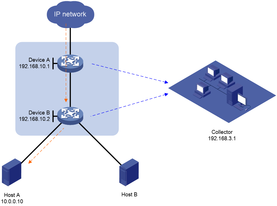
As shown in Figure 1, Host A and Host B access the external network through Device A and Device B. Some packets from the external network are missing on Host A. Configure MOD on the access device and aggregation device to identify whether packets are dropped during the forwarding process on the two devices.
Prerequisites
Configure IP addresses for devices, and make sure they can reach each other at Layer 3.
Procedures
1. Configure Device A:
a. Configure a flow group:
# Create advanced IPv4 ACL 3000, and configure a rule to match packets with destination IP address 10.0.0.10 for the ACL.
<DeviceA> system-view
[DeviceA] acl advanced 3000
[DeviceA-acl-ipv4-adv-3000] rule permit ip destination 10.0.0.10 0
[DeviceA-acl-ipv4-adv-3000] quit
# Create flow group 1 and configure it to reference ACL 3000.
[DeviceA] telemetry flow-group 1
[DeviceA-telemetry-flow-group-1] if-match acl 3000
# Configure the flow group to generate flow entries based on the destination IP address.
[DeviceA-telemetry-flow-group-1] template destination-ip
[DeviceA-telemetry-flow-group-1] quit
# Set the flow entry aging time to 10 minutes.
[DeviceA] telemetry flow-group aging-time 10
# Apply flow group 1.
[DeviceA] telemetry apply flow-group 1
b. Configure MOD:
# Configure the device ID for MOD as 192.168.10.1.
[DeviceA] telemetry mod
[DeviceA-telemetry-mod] device-id 192.168.10.1
[DeviceA-telemetry-mod] quit
# Create sampler samp, set the sampling mode to random, and set the sampling rate to 2 to the 8th power.
[DeviceA] sampler samp mode random packet-interval n-power 8
# Enable sampling for MOD, and reference sampler samp.
[DeviceA] telemetry mod
[DeviceA-telemetry-mod] sampler samp
# Encapsulate the packets sent to the collector by MOD with the following information: source IP address 192.168.10.1, destination IP address 192.168.3.1, source port number 1000, and destination port number 2333.
[DeviceA-telemetry-mod] collector source-ip 192.168.10.1 destination-ip 192.168.3.1 source-port 1000 destination-port 2333
# Configure MOD to monitor all packet drop reasons.
[DeviceA-telemetry-mod] reason-list all
[DeviceA-telemetry-mod] quit
2. Configure Device B.
Configure Device B in the same way Device A is configured except the device ID for MOD and the source IP address encapsulated in the packets sent to the collector.
Verifying the configuration
1. Verify the configuration on Device A:
# Display the ACL configuration.
<DeviceA> display acl 3000
Advanced IPv4 ACL 3000, 1 rule,
ACL's step is 5, start ID is 0
rule 0 permit ip destination 10.0.0.10 0
# Display the flow group configuration.
<DeviceA> display telemetry flow-group 1
Flow group 1 (Successful)
ACL : 3000
Template :
destination-ip
Aging time: 10 minutes
# Display the MOD configuration.
<DeviceA> display telemetry mod
Drop reason list:
higig-header-error
invalid-tpid
ip-multicast-error
ipv4-dip-miss
…Omitted…
Sampler : samp
Device ID : 192.168.10.1
Transport protocol : udp
Collector
Source IP : 192.168.10.1
Destination IP : 192.168.3.1
Source port : 1000
Destination port : 2333
2. Verify the configuration on Device B.
The configuration on Device B is the same as the configuration on Device A except the device ID for MOD and the source IP address encapsulated in the packets sent to the collector. (Details not shown.)
3. Verify the configuration on the collector.
When a packet destined for IP address 10.0.0.10 is dropped during the forwarding process on Device A and Device B, the collector can receive the packet drop reason and the characteristics of the dropped packet from the devices.
Example: Configuring MOD to send packets through gRPC
Network configuration
As shown in Figure 2, Host A and Host B access the external network through Device A and Device B. Some packets from the external network are missing on Host A. Configure MOD on the access device and aggregation device to identify whether packets are dropped during the forwarding process on the two devices.

Prerequisites
Configure IP addresses for devices, and make sure they can reach each other at Layer 3.
Procedures
1. Configure Device A:
a. Configure a flow group:
# Create advanced IPv4 ACL 3000, and configure a rule to match packets with destination IP address 10.0.0.10 for the ACL.
<DeviceA> system-view
[DeviceA] acl advanced 3000
[DeviceA-acl-ipv4-adv-3000] rule permit ip destination 10.0.0.10 0
[DeviceA-acl-ipv4-adv-3000] quit
# Create flow group 1 and configure it to reference ACL 3000.
[DeviceA] telemetry flow-group 1
[DeviceA-telemetry-flow-group-1] if-match acl 3000
# Configure the flow group to generate flow entries based on the destination IP address.
[DeviceA-telemetry-flow-group-1] template destination-ip
[DeviceA-telemetry-flow-group-1] quit
# Set the flow entry aging time to 50 minutes.
[DeviceA] telemetry flow-group aging-time 50
# Apply flow group 1.
[DeviceA] telemetry apply flow-group 1
b. Configure MOD:
# Configure the device ID for MOD as 192.168.10.1.
[DeviceA] telemetry mod
[DeviceA-telemetry-mod] device-id 192.168.10.1
[DeviceA-telemetry-mod] quit
# Create sampler samp, set the sampling mode to random, and set the sampling rate to 2 to the 8th power.
[DeviceA] sampler samp mode random packet-interval n-power 8
# Enable sampling for MOD, and reference sampler samp.
[DeviceA] telemetry mod
[DeviceA-telemetry-mod] sampler samp
# Configure MOD to use gRPC to send packets to the collector.
[DeviceA-telemetry-mod] transport-protocol grpc
# Configure MOD to monitor all packet drop reasons.
[DeviceA-telemetry-mod] reason-list all
[DeviceA-telemetry-mod] quit
c. Configure gRPC:
# Enable the gRPC service.
[DeviceA] grpc enable
# Create a sensor group named test, and add sensor path telemetryftrace/genevent.
[DeviceA] telemetry
[DeviceA-telemetry] sensor-group test
[DeviceA-telemetry-sensor-group-test] sensor path telemetryftrace/genevent
[DeviceA-telemetry-sensor-group-test] quit
# Create a destination group named collector1. Specify a collector that uses IPv4 address 192.168.3.1 and port number 50050.
[DeviceA-telemetry] destination-group collector1
[DeviceA-telemetry-destination-group-collector1] ipv4-address 192.168.3.1 port 50050
[DeviceA-telemetry-destination-group-collector1] quit
# Configure a subscription named A to bind sensor group test with destination group collector1.
[DeviceA-telemetry] subscription A
[DeviceA-telemetry-subscription-A] sensor-group test
[DeviceA-telemetry-subscription-A] destination-group collector1
[DeviceA-telemetry-subscription-A] quit
[DeviceA-telemetry] quit
2. Configure Device B.
Configure Device B in the same way Device A is configured except the device ID for MOD.
Verifying the configuration
1. Verify the configuration on Device A:
# Display the ACL configuration.
<DeviceA> display acl 3000
Advanced IPv4 ACL 3000, 1 rule,
ACL's step is 5, start ID is 0
rule 0 permit ip destination 10.0.0.10 0
# Display the flow group configuration.
<DeviceA> display telemetry flow-group 1
Flow group 1 (Successful)
ACL : 3000
Template :
destination-ip
Aging time: 50 minutes
# Display the MOD configuration.
<DeviceA> display telemetry mod
Drop reason list:
higig-header-error
invalid-tpid
ip-multicast-error
ipv4-dip-miss
…Omitted…
Sampler : samp
Device ID : 192.168.10.1
Transport protocol : gRPC
2. Verify the configuration on Device B.
The configuration on Device B is the same as the configuration on Device A except the device ID for MOD. (Details not shown.)
3. Verify the configuration on the collector.
When a packet destined for IP address 10.0.0.10 is dropped during the forwarding process on Device A and Device B, the collector (gRPC server) can receive the packet drop reason and the characteristics of the dropped packet from the devices (gRPC clients).
